EP0505299B1 - Dosing apparatus adaptable to various containers - Google Patents
Dosing apparatus adaptable to various containers Download PDFInfo
- Publication number
- EP0505299B1 EP0505299B1 EP92440003A EP92440003A EP0505299B1 EP 0505299 B1 EP0505299 B1 EP 0505299B1 EP 92440003 A EP92440003 A EP 92440003A EP 92440003 A EP92440003 A EP 92440003A EP 0505299 B1 EP0505299 B1 EP 0505299B1
- Authority
- EP
- European Patent Office
- Prior art keywords
- piece
- cylindrical
- annular
- wall
- face
- Prior art date
- Legal status (The legal status is an assumption and is not a legal conclusion. Google has not performed a legal analysis and makes no representation as to the accuracy of the status listed.)
- Expired - Lifetime
Links
- 239000000463 material Substances 0.000 claims abstract description 7
- 230000000284 resting effect Effects 0.000 claims description 4
- 239000013013 elastic material Substances 0.000 claims 3
- 230000006978 adaptation Effects 0.000 claims 1
- 238000004519 manufacturing process Methods 0.000 abstract description 6
- 230000000694 effects Effects 0.000 abstract description 2
- 230000006835 compression Effects 0.000 description 3
- 238000007906 compression Methods 0.000 description 3
- 239000007788 liquid Substances 0.000 description 2
- 238000000465 moulding Methods 0.000 description 2
- 229920003051 synthetic elastomer Polymers 0.000 description 2
- 238000007599 discharging Methods 0.000 description 1
- 230000004048 modification Effects 0.000 description 1
- 238000012986 modification Methods 0.000 description 1
- 230000003647 oxidation Effects 0.000 description 1
- 238000007254 oxidation reaction Methods 0.000 description 1
- 235000011837 pasties Nutrition 0.000 description 1
- 239000003755 preservative agent Substances 0.000 description 1
- 239000012815 thermoplastic material Substances 0.000 description 1
Images


Classifications
-
- G—PHYSICS
- G01—MEASURING; TESTING
- G01F—MEASURING VOLUME, VOLUME FLOW, MASS FLOW OR LIQUID LEVEL; METERING BY VOLUME
- G01F11/00—Apparatus requiring external operation adapted at each repeated and identical operation to measure and separate a predetermined volume of fluid or fluent solid material from a supply or container, without regard to weight, and to deliver it
- G01F11/02—Apparatus requiring external operation adapted at each repeated and identical operation to measure and separate a predetermined volume of fluid or fluent solid material from a supply or container, without regard to weight, and to deliver it with measuring chambers which expand or contract during measurement
- G01F11/021—Apparatus requiring external operation adapted at each repeated and identical operation to measure and separate a predetermined volume of fluid or fluent solid material from a supply or container, without regard to weight, and to deliver it with measuring chambers which expand or contract during measurement of the piston type
- G01F11/025—Apparatus requiring external operation adapted at each repeated and identical operation to measure and separate a predetermined volume of fluid or fluent solid material from a supply or container, without regard to weight, and to deliver it with measuring chambers which expand or contract during measurement of the piston type with manually operated pistons
-
- B—PERFORMING OPERATIONS; TRANSPORTING
- B05—SPRAYING OR ATOMISING IN GENERAL; APPLYING FLUENT MATERIALS TO SURFACES, IN GENERAL
- B05B—SPRAYING APPARATUS; ATOMISING APPARATUS; NOZZLES
- B05B11/00—Single-unit hand-held apparatus in which flow of contents is produced by the muscular force of the operator at the moment of use
- B05B11/0005—Components or details
- B05B11/0062—Outlet valves actuated by the pressure of the fluid to be sprayed
- B05B11/007—Outlet valves actuated by the pressure of the fluid to be sprayed being opened by deformation of a sealing element made of resiliently deformable material, e.g. flaps, skirts, duck-bill valves
-
- B—PERFORMING OPERATIONS; TRANSPORTING
- B05—SPRAYING OR ATOMISING IN GENERAL; APPLYING FLUENT MATERIALS TO SURFACES, IN GENERAL
- B05B—SPRAYING APPARATUS; ATOMISING APPARATUS; NOZZLES
- B05B11/00—Single-unit hand-held apparatus in which flow of contents is produced by the muscular force of the operator at the moment of use
- B05B11/01—Single-unit hand-held apparatus in which flow of contents is produced by the muscular force of the operator at the moment of use characterised by the means producing the flow
- B05B11/02—Membranes or pistons acting on the contents inside the container, e.g. follower pistons
- B05B11/028—Pistons separating the content remaining in the container from the atmospheric air to compensate underpressure inside the container
- B05B11/029—Pistons separating the content remaining in the container from the atmospheric air to compensate underpressure inside the container located on top of the remaining content
-
- B—PERFORMING OPERATIONS; TRANSPORTING
- B05—SPRAYING OR ATOMISING IN GENERAL; APPLYING FLUENT MATERIALS TO SURFACES, IN GENERAL
- B05B—SPRAYING APPARATUS; ATOMISING APPARATUS; NOZZLES
- B05B11/00—Single-unit hand-held apparatus in which flow of contents is produced by the muscular force of the operator at the moment of use
- B05B11/01—Single-unit hand-held apparatus in which flow of contents is produced by the muscular force of the operator at the moment of use characterised by the means producing the flow
- B05B11/10—Pump arrangements for transferring the contents from the container to a pump chamber by a sucking effect and forcing the contents out through the dispensing nozzle
- B05B11/1001—Piston pumps
- B05B11/1004—Piston pumps comprising a movable cylinder and a stationary piston
-
- B—PERFORMING OPERATIONS; TRANSPORTING
- B05—SPRAYING OR ATOMISING IN GENERAL; APPLYING FLUENT MATERIALS TO SURFACES, IN GENERAL
- B05B—SPRAYING APPARATUS; ATOMISING APPARATUS; NOZZLES
- B05B11/00—Single-unit hand-held apparatus in which flow of contents is produced by the muscular force of the operator at the moment of use
- B05B11/01—Single-unit hand-held apparatus in which flow of contents is produced by the muscular force of the operator at the moment of use characterised by the means producing the flow
- B05B11/10—Pump arrangements for transferring the contents from the container to a pump chamber by a sucking effect and forcing the contents out through the dispensing nozzle
- B05B11/1042—Components or details
- B05B11/1064—Pump inlet and outlet valve elements integrally formed of a deformable material
-
- B—PERFORMING OPERATIONS; TRANSPORTING
- B05—SPRAYING OR ATOMISING IN GENERAL; APPLYING FLUENT MATERIALS TO SURFACES, IN GENERAL
- B05B—SPRAYING APPARATUS; ATOMISING APPARATUS; NOZZLES
- B05B11/00—Single-unit hand-held apparatus in which flow of contents is produced by the muscular force of the operator at the moment of use
- B05B11/01—Single-unit hand-held apparatus in which flow of contents is produced by the muscular force of the operator at the moment of use characterised by the means producing the flow
- B05B11/10—Pump arrangements for transferring the contents from the container to a pump chamber by a sucking effect and forcing the contents out through the dispensing nozzle
- B05B11/1042—Components or details
- B05B11/1066—Pump inlet valves
- B05B11/1067—Pump inlet valves actuated by pressure
- B05B11/1069—Pump inlet valves actuated by pressure the valve being made of a resiliently deformable material or being urged in a closed position by a spring
-
- B—PERFORMING OPERATIONS; TRANSPORTING
- B05—SPRAYING OR ATOMISING IN GENERAL; APPLYING FLUENT MATERIALS TO SURFACES, IN GENERAL
- B05B—SPRAYING APPARATUS; ATOMISING APPARATUS; NOZZLES
- B05B11/00—Single-unit hand-held apparatus in which flow of contents is produced by the muscular force of the operator at the moment of use
- B05B11/01—Single-unit hand-held apparatus in which flow of contents is produced by the muscular force of the operator at the moment of use characterised by the means producing the flow
- B05B11/10—Pump arrangements for transferring the contents from the container to a pump chamber by a sucking effect and forcing the contents out through the dispensing nozzle
- B05B11/1042—Components or details
- B05B11/1073—Springs
- B05B11/1076—Traction springs, e.g. stretchable sleeve
-
- B—PERFORMING OPERATIONS; TRANSPORTING
- B05—SPRAYING OR ATOMISING IN GENERAL; APPLYING FLUENT MATERIALS TO SURFACES, IN GENERAL
- B05B—SPRAYING APPARATUS; ATOMISING APPARATUS; NOZZLES
- B05B11/00—Single-unit hand-held apparatus in which flow of contents is produced by the muscular force of the operator at the moment of use
- B05B11/01—Single-unit hand-held apparatus in which flow of contents is produced by the muscular force of the operator at the moment of use characterised by the means producing the flow
- B05B11/10—Pump arrangements for transferring the contents from the container to a pump chamber by a sucking effect and forcing the contents out through the dispensing nozzle
- B05B11/1042—Components or details
- B05B11/1073—Springs
- B05B11/1077—Springs characterised by a particular shape or material
-
- B—PERFORMING OPERATIONS; TRANSPORTING
- B05—SPRAYING OR ATOMISING IN GENERAL; APPLYING FLUENT MATERIALS TO SURFACES, IN GENERAL
- B05B—SPRAYING APPARATUS; ATOMISING APPARATUS; NOZZLES
- B05B11/00—Single-unit hand-held apparatus in which flow of contents is produced by the muscular force of the operator at the moment of use
- B05B11/01—Single-unit hand-held apparatus in which flow of contents is produced by the muscular force of the operator at the moment of use characterised by the means producing the flow
- B05B11/02—Membranes or pistons acting on the contents inside the container, e.g. follower pistons
- B05B11/028—Pistons separating the content remaining in the container from the atmospheric air to compensate underpressure inside the container
Definitions
- the present invention relates to a metering device adaptable to various containers, bottles, tubes, jars, rigid or flexible, used in particular in the field of pharmacy and cosmetology.
- WO-A-90/05091 describes a device comprising a tubular part closed at its upper part by a wall pierced axially with an orifice closed by a valve for the evacuation of the contents, said tubular part being covered by a cover. adapted to move in translation, the dose to be extracted from the container being formed in an expandable chamber delimited by said tubular part and said cover.
- the present invention makes it possible to remedy all of these drawbacks of known devices by proposing a metering device comprising only a reduced number of easily assembled parts, therefore of reduced manufacturing cost , and enabling the functions of the most sophisticated metering devices to be fulfilled, namely: creating the dose, expelling it, reproducing it, preventing the intake of outside air towards the inside and remaining watertight.
- the metering device object of the invention comprises an inner part made of an elastic deformable material adapting in an outer part, or cover, made of a rigid material, the assembly being able to adapt to a container either through a third part, either directly in the case where this container has an assembly portion of suitable shape, the bottles or jars on which this metering device can be adapted, which may or may not be provided with a compression system such as A piston.
- the inner part of the device according to the invention is preferably produced by molding a synthetic elastomer which gives it qualities of deformability and elasticity making it possible to seal the device, to allow the dose to escape, and d vacuum the contents to create a new dose.
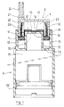
- the metering device object of the invention comprises an inner part 1 (made of synthetic elastomer placed in a cover 2 (made of thermo-plastic material), the assembly s' adapting on a container 3.
- the container 3 is provided internally, at its lower part, with a piston 30 which can slide inside said container 3 upwards as its contents 31 are emptied.
- the container 3 is extended at its upper part by a cylindrical part 32 closed at its upper part by a wall 33 axially pierced with an orifice 34 for discharging the content 31.
- the cylindrical part 32 is concentrically surrounded by a cylindrical cage 35 providing between them a cylindrical annular space 36.
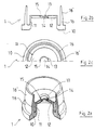
- the inner part 1 of generally cylindrical shape, has an annular part-10 whose diametrical dimensions are those of space 36 and whose inner edge is extended towards the top by a tubular part 11 whose upper opening is closed by a wall 12 pierced in its center with an orifice 13 partially closed by a valve 14 fixed to the edges of said orifice 13 by one or more tabs 15 authorizing the lifting of said valve 15.
- the part 1 also includes externally and concentrically with the tubular part 11, a tubular part 16 whose lower part, attached to the annular part 10, is cylindrical, and is extended by an upper part 16 'frustoconical whose inner face is in continuation of the inside of the lower part.
- the cover 2 of the metering device comprises a cylindrical body 20 closed at its upper part by a wall 21, and whose outside diameter is slightly less than the inside diameter of the cage 35. It has internally on the wall 21 an annular rim 22 of diameter outside equal to the inside diameter of the tubular part 16 of the part 1.
- the annular space 23 formed between the annular rim 22 and the body 20 is extended by an expulsion conduit 24.
- the cover 2 tightly covers the tubular part 16 of the part 1, so that the inner face of the body 20 is in close contact with the outer face of the tubular part 16 , the lower edge of the body 20 resting on the part annular 10 of the part 1, and the upper end 16 ′ of the tubular part 16 fitting into the annular space 23, the internal face of said part 16 ′ being in close contact with the external face of the annular rim 22.
- the internal face of the wall 21 of the cover 2 is located at a certain distance from the wall 12 of the part 1, thus providing a certain volume 4.
- the cover 2 assembled with the part 1 is placed on the container 3, the annular part 10 being engaged in the space 36, the tubular part 11 being positioned on the cylindrical part 32, until the part 12 comes into contact with its wall 33, the heights of the different cylindrical parts being such that the distance between the lower face of the annular part 10 of the part 1 and the bottom of the space 36 is equal to that separating the internal face of the wall 21 and the upper lace of the wall 12 of the piece 1.
- the volume 4 is fixed during manufacture, and constitutes the desired volume of the dose.
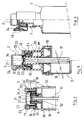
- the device can be adapted to any container 3 provided at its opening with a thread, for example, it is then enough to adapt on said thread a third piece 5 taking up the shapes of the assembly part of the container described above, and provided with a thread 50.
- the device will in this case be advantageously supplemented by a modification of the part 1 which comprises a tubular part 17 deploying internally and downwards under the part 12, whose function is the same as the part 16 with respect to the outside air, deforming to allow outside air to enter the container 3 through the orifice 52, but preventing any exit of the content 31 when the container is held upside down.
- the tubular part 17 partially occupies the space 36 'delimited by the cylindrical part 32 and a second cylindrical part 32' which surrounds it concentrically, the space 36 'communicating with the interior space of the container 3 through the orifice 52.
- the metering device according to the invention can be adapted on a container 3 provided with a plunger 37 opening onto the orifice 34, that the intake of outside air can s' carry out in the container 3 but without this air coming into contact with the content 31.
- a piston 30 placed in the upper part of the container 3 around the plunger 37 can move downward, pushing the content 31 towards the mouth of the plunger 37, the outside air entering the container behind the piston 30 through orifices 38 formed in the bottom of the space 36.
- FIG. 6 it can be seen that during the molding operation of the part 1 an external plug 18 can be manufactured, making it possible to close the evacuation duct 24.
Landscapes
- Physics & Mathematics (AREA)
- Fluid Mechanics (AREA)
- General Physics & Mathematics (AREA)
- Containers And Packaging Bodies Having A Special Means To Remove Contents (AREA)
- Closures For Containers (AREA)
- Infusion, Injection, And Reservoir Apparatuses (AREA)
- Medicines That Contain Protein Lipid Enzymes And Other Medicines (AREA)
- Measurement Of Radiation (AREA)
- Basic Packing Technique (AREA)
Abstract
Description
La présente invention a pour objet un dispositif doseur adaptable sur des contenants divers, flacons, tubes, pots, rigides ou souples, utilisés notamment dans le domaine de la pharmacie et de la cosmétologie.The present invention relates to a metering device adaptable to various containers, bottles, tubes, jars, rigid or flexible, used in particular in the field of pharmacy and cosmetology.
Dans certains domaines, notamment ceux précités, il peut être nécessaire d'extraire des produits liquides ou pâteux de leur contenant en doses plus ou moins précises.In certain fields, in particular those mentioned above, it may be necessary to extract liquid or pasty products from their container in more or less precise doses.
Il existe actuellement des dispositifs doseurs permettant d'obtenir ce résultat, c'est-à-dire la création et l'expulsion d'une dose.There are currently metering devices for achieving this result, that is to say the creation and expulsion of a dose.
Ainsi le document WO-A-90/05091 décrit un dispositif comprenant une partie tubulaire fermée à sa partie supérieure par une paroi percée axialement d'un orifice obturé par un clapet pour l'évacuation du contenu, ladite partie tubulaire étant recouverte par un capot adapté à se déplacer en translation, la dose à extraire du contenant étant formée dans une chambre expansible délimitée par ladite partie tubulaire et ledit capot.Thus the document WO-A-90/05091 describes a device comprising a tubular part closed at its upper part by a wall pierced axially with an orifice closed by a valve for the evacuation of the contents, said tubular part being covered by a cover. adapted to move in translation, the dose to be extracted from the container being formed in an expandable chamber delimited by said tubular part and said cover.
Les dispositifs doseurs connus a ce jour, s'ils donnent satisfaction dans la création et l'expulsion d'une dose, n'en présentent pas moins des inconvénients, notamment en ce qui concerne leur fabrication.The metering devices known to date, if they give satisfaction in the creation and expulsion of a dose, nevertheless have drawbacks, in particular with regard to their manufacture.
En effet, pour réaliser un dispositif doseur il est nécessaire d'assembler plusieurs pièces telles que bille, ressorts, clapets, bouchon et autres. Au coût de toutes ces pièces il faut ajouter le coût d'assemblage, manuel ou automatique, qui représente une part importante du coût de fabrication.Indeed, to make a metering device it is necessary to assemble several parts such as ball, springs, valves, plug and others. To the cost of all these parts must be added the cost of assembly, manual or automatic, which represents a significant part of the manufacturing cost.
De plus ces dispositifs présentent des inconvénients tels qu'une étanchéité insuffisante, et une reprise d'air extérieur vers l'intérieur après la phase d'expulsion, ce qui nécessite d'incorporer au contenu des conservateurs afin d'éviter son oxydation.In addition, these devices have disadvantages such as an insufficient seal, and a return of outside air inward after the expulsion phase, which requires incorporating the contents of preservatives to avoid its oxidation.
Certains dispositifs doseurs connus permettent d'éviter ces inconvénients, mais par adjonction de pièces supplémentaires, ce qui augmente leur coût de fabrication.Certain known metering devices make it possible to avoid these drawbacks, but by adding additional parts, which increases their manufacturing cost.
La présente invention, telle que définie dans les revendications indépendantes 1 à 3, permet de remédier à tous ces inconvénients des dispositifs connus en proposant un dispositif doseur ne comportant qu'un nombre réduit de pièces facilement assemblables, donc d'un coût de fabrication réduit, et permettant d'accomplir les fonctions des dispositifs doseurs les plus perfectionnés, à savoir: créer la dose, l'expulser, la reproduire, éviter la reprise d'air extérieur vers l'intérieur et rester étanche.The present invention, as defined in
Le dispositif doseur objet de l'invention comporte une pièce intérieure réalisée en un matériau déformable élastique s'adaptant dans une pièce extérieure, ou capot, réalisée en un matériau rigide, l'ensemble pouvant s'adapter sur un contenant soit par l'intermédiaire d'une troisième pièce, soit directement dans le cas où ce contenant présente une partie d'assemblage de forme appropriée, les flacons ou pots sur lesquels peut être adapté ce dispositif doseur pouvant ou non être pourvus d'un système de compression tel qu'un piston.The metering device object of the invention comprises an inner part made of an elastic deformable material adapting in an outer part, or cover, made of a rigid material, the assembly being able to adapt to a container either through a third part, either directly in the case where this container has an assembly portion of suitable shape, the bottles or jars on which this metering device can be adapted, which may or may not be provided with a compression system such as A piston.
La pièce intérieure du dispositif selon l'invention est de préférence réalisée par moulage d'un élastomère de synthèse qui lui confère des qualités de déformabilité et d'élasticité permettant d'assurer l'étanchéité du dispositif, de laisser échapper la dose, et d'aspirer le contenu pour créer une nouvelle dose.The inner part of the device according to the invention is preferably produced by molding a synthetic elastomer which gives it qualities of deformability and elasticity making it possible to seal the device, to allow the dose to escape, and d vacuum the contents to create a new dose.
Les avantages et les caractéristiques de la présente invention ressortiront plus clairement de la description qui suit et qui se rapporte au dessin annexé, lequel en représente un mode de réalisation non limitatif.The advantages and characteristics of the present invention will emerge more clearly from the description which follows and which refers to the appended drawing, which represents a non-limiting embodiment thereof.
Dans le dessin annexé :
- la figure 1 représente une vue en coupe verticale d'un flacon muni d'un dispositif doseur selon l'invention.
- la figure 2a représente une vue en perspective avec arraché partiel de la pièce intérieure de ce dispositif.
- la figure 2b représente une vue en coupe de la même pièce.
- la figure 2c représente une vue partielle en plan de la même pièce.
- la figure 3 représente une vue en coupe verticale du flacon de la figure 1, lorsqu'une pression est appliquée sur le capot.
- la figure 4 représente une vue en coupe verticale d'une variante du dispositif selon l'invention, adapté au moyen d'une troisième pièce sur un contenant classique, en l'occurence un flacon rigide avec tube plongeur.
- la figure 5 représente une vue en coupe d'un flacon équipé d'un dispositif doseur, le flacon étant rigide et avec tube plongeur.
- la figure 6 représente une vue en coupe verticale partielle d'un flacon équipé d'un dispositif doseur dont la pièce intérieure comprend un système d'obturation extérieur.
- la figure 7 représente une vue en coupe verticale partielle d'un flacon muni d'un dispositif doseur, le flacon étant pourvu d'un piston pour la reprise d'air et permettant à l'utilisateur d'en voir le contenu.
- Figure 1 shows a vertical sectional view of a bottle provided with a metering device according to the invention.
- Figure 2a shows a perspective view with partial cutaway of the inner part of this device.
- Figure 2b shows a sectional view of the same part.
- Figure 2c shows a partial plan view of the same part.
- Figure 3 shows a vertical sectional view of the bottle of Figure 1, when pressure is applied to the cover.
- 4 shows a vertical sectional view of a variant of the device according to the invention, adapted by means of a third part on a conventional container, in this case a rigid bottle with dip tube.
- 5 shows a sectional view of a bottle equipped with a metering device, the bottle being rigid and with dip tube.
- Figure 6 shows a partial vertical sectional view of a bottle equipped with a metering device, the inner part of which comprises an external closure system.
- 7 shows a partial vertical sectional view of a bottle provided with a metering device, the bottle being provided with a piston for the air intake and allowing the user to see the contents.
Si on se réfère à la figure 1 on peut voir que le dispositif doseur objet de l'invention comporte une pièce intérieure 1 (réalisée en élastomère de synthèses placée dans un capot 2 (réalisé en matière thermo-plastique), l'ensemble s'adaptant sur un contenant 3.If we refer to Figure 1 we can see that the metering device object of the invention comprises an inner part 1 (made of synthetic elastomer placed in a cover 2 (made of thermo-plastic material), the assembly s' adapting on a
Le contenant 3 est muni intérieurement, à sa partie basse, d'un piston 30 pouvant coulisser à l'intérieur dudit contenant 3 vers le haut au fur et à mesure du vidage de son contenu 31.The
Le contenant 3 est prolongé à sa partie supérieure par une partie cylindrique 32 fermée à sa partie supérieure par une paroi 33 percée axialement d'un orifice 34 d'évacuation du contenu 31. La partie cylindrique 32 est entourée concentriquement d'une cage cylindrique 35 ménageant entre elles un espace annulaire cylindrique 36.The
En se réfèrant aux figures 2a, 2b et 2c, on peut voir que la pièce intérieure 1, de forme générale cylindrique, comporte une-partie 10 annulaire dont les dimension diamétrales sont celles de l'espace 36 et dont le bord intérieur est prolongé vers le haut par une partie tubulaire 11 dont l'ouverture supérieure est fermée par une paroi 12 percée en son centre d'un orifice 13 obturé partiellement par un clapet 14 fixé aux bords dudit orifice 13 par une ou plusieurs languettes 15 autorisant le soulèvement dudit clapet 15. La pièce 1 comporte également extérieurement et concentriquement à la partie tubulaire 11, une partie tubulaire 16 dont la partie inférieure, rattachée à la partie annulaire 10, est cylindrique, et est prolongée par une partie supérieure 16' tronconique dont la face intérieure est dans le prolongement de la face intérieure de la partie inférieure.Referring to Figures 2a, 2b and 2c, we can see that the
Le capot 2 du dispositif doseur comporte un corps cylindrique 20 fermé à sa partie supérieure par une paroi 21, et dont le diamètre extérieur est légèrement inférieur au diamètre intérieur de la cage 35. Il comporte intérieurement sur la paroi 21 un rebord annulaire 22 de diamètre extérieur égal au diamètre intérieur de la partie tubulaire 16 de la pièce 1. L'espace annulaire 23 ménagé entre le rebord annulaire 22 et le corps 20 est prolongé par un conduit 24 d'expulsion.The
Lors de l'assemblage de la pièce 1 et du capot 2, le capot 2 recouvre étroitement la partie tubulaire 16 de la pièce 1, de manière que la face intérieure du corps 20 soit en contact étroit avec la face extérieure de la partie tubulaire 16, le rebord inférieur du corps 20 reposant sur la partie annulaire 10 de la pièce 1, et l'extrémité supérieure 16' de la partie tubulaire 16 s'insérant dans l'espace annulaire 23, la face intérieure de ladite partie 16' étant en contact étroit avec la face extérieure du rebord annulaire 22. La face interne de la paroi 21 du capot 2 se trouve à une certaine distance de la paroi 12 de la pièce 1, ménageant ainsi un certain volume 4.During the assembly of the
Le capot 2 assemblé avec la pièce 1 est placé sur le contenant 3, la partie annulaire 10 étant engagée dans l'espace 36, la partie tubulaire 11 se positionnant sur la partie cylindrique 32, jusqu'à ce que la partie 12 entre en contact avec sa paroi 33, les hauteurs des différentes parties cylindriques étant telles que la distance entre la face inférieure de la partie annulaire 10 de la pièce 1 et le fond de l'espace 36 soit égale à celle séparant la face interne de la paroi 21 et la lace supérieure de la paroi 12 de la pièce 1.The
Si on se réfère maintenant à la figure 3, on peut voir que lorsque l'on exerce une pression verticale, symbolisée par la flèche F, sur le capot 2, la pièce 1, qui est élastique, se déforme en s'allongeant au niveau de sa partie tubulaire 11, l'air enfermé dans l'espace 36 pouvant s'échapper grâce à la différence de diamètre existant entre la cage 35 et la partie annulaire 10, le volume 4 est comprimé, et sous l'effet de cette compression la partie supérieure 16′ de la partie tubulaire 16 se décolle du rebord annulaire 22 ce qui permet au contenu du volume 4 de s'échapper par l'espace annulaire 23 puis par le conduit d'évacuation 24. Dans le même temps, cette même compression applique le clapet 14 sur l'orifice 34, empêchant tout échange entre le contenant 3 et le volume 4.If we now refer to FIG. 3, we can see that when we exert a vertical pressure, symbolized by the arrow F, on the
Lorsque l'on relâche la pression sur le capot 2, la partie tubulaire 11 de la pièce 1 retrouve sa forme initiale, ce qui créé une dépression, les parties extrêmes 16′ de la partie tubulaire de la pièce 1 se plaquent sur le rebord annulaire 22, le clapet 14 se soulève, et le contenu 31 est aspiré et vient occuper le volume 4, pendant que le piston 30 monte dans le contenant 3. Il n'y a donc pas de reprise d'air extérieur vers l'intérieur, d'une part l'aspiration s'effectue au niveau du contenu 31, et d'autre part l'air est arrêté par le joint hermétique que constitue la partie 16' appliquée sur le rebord annulaire 22.When the pressure is released on the
On peut comprendre que lorsqu'un tel dispositif doseur est monté sur un contenant souple, du type tube, l'aspiration du contenu lors du relâchement de la pression se traduise par une déformation extérieure dudit contenant.It can be understood that when such a metering device is mounted on a flexible container, of the tube type, the aspiration of the content when the pressure is released results in an external deformation of said container.
Le volume 4 est fixé lors de la fabrication, et constitue le volume désiré de la dose.The
Si on se réfère maintenant à la figure 4, on peut voir que le dispositif peut être adapté sur tout contenant 3 muni à son ouverture d'un pas de vis par exemple, il suffit alors d'adapter sur ledit pas de vis une troisième pièce 5 reprenant les formes de la partie d'assemblage du contenant précédemment décrit, et munie d'un pas de vis 50.If we now refer to Figure 4, we can see that the device can be adapted to any
Dans le cas particulier présenté d'un contenant rigide rempli d'un contenu liquide 31 et équipé d'un plongeur 51, il y a nécessité de reprise d'air extérieur, celle-ci s'effectuant par un orifice 52 en communiquant avec l'extérieur. Le dispositif sera en ce cas avantageusement complété par une modification de la pièce 1 qui comporte une partie tubulaire 17 se déployant intérieurement et vers le bas sous la partie 12, dont la fonction est la même que la partie 16 vis-à-vis de l'air extérieur, se déformant pour laisser pénétrer l'air extérieur dans le contenant 3 par l'orifice 52, mais empêchant toute sortie du contenu 31 lorsque le récipient est maintenu tête en bas. La partie tubulaire 17 occupe partiellement l'espace 36' délimité par la pièce cylindrique 32 et une deuxième pièce cylindrique 32' qui l'entoure concentriquement, l'espace 36' communiquant avec l'espace intérieur du contenant 3 par l'orifice 52.In the particular case presented of a rigid container filled with a
Si on se réfère ensuite à la figure 5 on peut voir que le dispositif doseur selon l'invention peut être adapté sur un contenant 3 muni d'un plongeur 37 débouchant sur l'orifice 34, que la reprise d'air extérieur peut s'effectuer dans le contenant 3 mais sans que cet air n'entre en contact avec le contenu 31. En effet un piston 30 placé dans la partie supérieure du contenant 3 autour du plongeur 37, peut se déplacer vers le bas, repoussant le contenu 31 vers l'embouchure du plongeur 37, l'air extérieur entrant dans le contenant derrière le piston 30 par des orifices 38 pratiqués dans le fond de l'espace 36.If we then refer to Figure 5 we can see that the metering device according to the invention can be adapted on a
Si on se réfère à la figure 6, on peut voir que lors de l'opération de moulage de la pièce 1 un bouchon extérieur 18 peut être fabriqué, permettant d'obturer le conduit d'évacuation 24.If reference is made to FIG. 6, it can be seen that during the molding operation of the
Si on se réfère enfin à la figure 7, on voit qu'il est possible de reprendre partiellement le dispositif de la figure 5, à :avoir un piston travaillant de haut en bas, pour un contenant non muni d'un plongeur et pourvu d'une double paroi, une paroi extérieure 39 transparente et une paroi intérieure 39′ opaque, l'espace entre les deux parois étant communiquant en partie inférieure avec l'intérieur du contenant 3 dans lequel évolue le piston 30. Dans ce cas, lors de la création d'une dose dans le volume 4, le contenu 31 remonte entre les parois 39 et 39′, étant ainsi visible de l'extérieur, pour aller remplir le volume 4, la reprise d'air extérieur se faisant derrière le piston 30, et n'entrant pas en contact avec le contenu 31.If we finally refer to Figure 7, we see that it is possible to partially resume the device of Figure 5, to: have a piston working from top to bottom, for a container not provided with a plunger and provided with 'a double wall, a transparent
Il est également possible de réaliser un dispositif doseur permettant le mélange de plusieurs produits au moment de la création de la dose dans le volume 4.It is also possible to make a dosing device allowing the mixing of several products at the time of creation of the dose in
Il va de soi que la présente invention ne saurait être limitée à la description qui précède de certains de ses modes de réalisation, susceptibles de subir des modifications sans pour autant sortir du cadre de l'invention.It goes without saying that the present invention cannot be limited to the foregoing description of some of its embodiments, which are capable of being modified without departing from the scope of the invention.
Claims (4)
- Dosing apparatus adaptable to various rigid or flexible containers such as bottles, tubes or pots, one part of the assembly comprising a cylindrical piece (32) closed at its upper part by a wall (33) pierced axially by an orifice (34) sealed by a flap (14) for evacuation of the contents (31) of the container (3), characterized in that it comprises an inner piece (1) made of a deformable elastic material placed in an outer piece or cap (2) made of a rigid material, the assembly being adapted to the said container (3) and the cylindrical piece (32) being surrounded concentrically by a cylindrical cage (35) with between them an annular space (36); the inner piece (1) of generally cylindrical form comprising an annular part (10), the inner edge of which is extended upwards by a tubular part (11), the upper opening of which is closed by a horizontal wall (12) pierced in its centre by an orifice (13) partially sealed by the flap (14) fixed at the edges of the said orifice (13) and also comprising, externally and concentrically to the tubular part (11), a cylindrical tubular part (16) attached by its base to the annular part (10) and extended by a truncated upper part (16') of which the inner face is the extension of the inner face of the lower cylindrical part (16); the cap (2) comprising a cylindrical body (20) which closely clasps the tubular part (16) of the piece (1) and of which the external diameter is slightly less than the internal diameter of the cage (35), the lower rim of the said body (20) resting on the annular part (10) of the piece (1) and the said cylindrical body (20), closed at its upper part by a wall (21), comprising also on the inside on the said wall (21) an annular rim (22) of external diameter equal to the internal diameter of the tubular part (16) of the inner piece (1), the upper end (16') of which is inserted in the annular space (23) which is arranged between the said annular rim (22) and the said cylindrical body (20) and which is extended upwards by an expulsion tube (24), the inner face of the said part (16') being in close contact with the outer face of the annular rim (22) whereas the internal face of the upper wall (21) of the cap (2) is at a certain distance from the horizontal wall (12) of the piece (1), thus providing a certain space (4) between one and the other; the annular part (10) of the inner piece (1) being positioned in the space (36) between the cylindrical cage (35) and the cylindrical piece (32) closely surrounded by the tubular part (11) of the said inner piece (1), the horizontal wall (12) of which covers its upper wall (33), the heights of the various cylindrical parts being such that the distance between the lower face of the annular part (10) of the said inner piece (1) and the base of the space (36) is equal to that separating the inner face of the upper wall (21) of the said cap (2) and the upper face of the horizontal wall (12) of the said piece (1).
- Dosing apparatus adaptable to various rigid or flexible containers such as bottles, tubes or pots, one part of the assembly part comprising a cylindrical piece (32) closed at its upper part by a wall (33) pierced axially by an orifice (34) sealed by a flap (14) for evacuation of the contents (31) of the container (3), characterized in that it comprises an inner piece (1) made of a deformable elastic material placed in an outer piece or cap (2) made of a rigid material, the assembly being adapted to the said container (3) and the cylindrical piece (32) being surrounded concentrically by a cylindrical cage (35) with between them an annular space (36); the inner piece (1) of generally cylindrical form comprising an annular part (10), the inner edge of which is extended upwards by a tubular part (11), the upper opening of which is partially closed by a horizontal wall (12) extended downwards by a tubular part (17) which partially occupies the space (36') delimited by the cylindrical piece (32) and a second cylindrical piece (32') which surrounds it concentrically, the said space (36') communicating with the inner space of the container (3) by an opening (52); the inner piece (1) also comprising, externally and concentrically to the tubular part (11), a cylindrical tubular part (16) attached by its base to the annular part (10) and extended by a truncated upper part (16') of which the inner face is the extension of the inner face of the lower cylindrical part (16); the cap (2) comprising a cylindrical body (20) which closely clasps the tubular part (16) of the inner piece (1) and of which the external diameter is slightly less than the internal diameter of the cage (35), the lower rim of the said body (20) resting on the annular part (10) of the piece (1) and the said cylindrical body (20), closed at its upper part by a wall (21), comprising on the inside, on the said wall (21), an annular rim (22) of external diameter equal to the internal diameter of the tubular part (16) of the inner piece (1), the upper end (16') of which is inserted in the annular space (23) which is arranged between the said annular rim (22) and the said cylindrical body (20) and which is extended upwards by an expulsion pipe (24), the inner face of the said part (16') being in close contact with the outer face of the annular rim (22) whereas the internal face of the upper wall (21) of the cap (2) is at a certain distance from the horizontal wall (12) of the inner piece (1), thus providing a certain space (4) between one and the other; the annular part (10) of the inner piece (1) being positioned in the space (36) between the cylindrical cage (35) and the cylindrical piece (32) closely surrounded by the tubular part (11) of the said piece (1), the horizontal wall (12) of which partially covers its upper wall (33); the heights of the various cylindrical parts being such that the distance between the lower face of the annular part (10) of the said piece (1) and the base of the space (36) is equal to that separating the inner face of the upper wall (21) of the said cap (2) and the upper face of the horizontal wall (12) of the said inner piece (1).
- Dosing apparatus adaptable to various rigid or flexible containers such as bottles, tubes or pots, one part of the assembly part comprising a cylindrical piece (32) closed at its upper part by a wall (33) pierced axially by an orifice (34) sealed by a flap (14) for evacuation of the contents (31) of the container (3), characterized in that it comprises an inner piece (1) made of a deformable elastic material placed in an outer piece or cap (2) made of a rigid material, the assembly being adapted to the said container (3) and the cylindrical piece (32) being surrounded concentrically by a cylindrical cage (35) with between them an annular space (36) which communicates with the interior of the container (3) by orifices (38); the inner piece (1) of generally cylindrical form comprising an annular part (10), the inner edge of which is extended upwards by a tubular part (11), the upper opening of which is partially closed by a horizontal wall (12), and also comprising, externally and concentrically to the tubular part (11), a cylindrical tubular part (16) attached by its base to the annular part (10) and extended by a truncated upper part (16') of which the inner face is the extension of the inner face of the lower cylindrical part (16); the cap (2) comprising a cylindrical body (20) which closely surrounds the tubular part (16) of the inner piece (1) and of which the external diameter is slightly less than the internal diameter of the cage (35), the lower rim of the said body (20) resting on the annular part (10) of the inner piece (1) and the said cylindrical body (20), closed at its upper part by a wall (21), comprising on the inside, on the said wall (21), an annular rim (22) of external diameter equal to the internal diameter of the tubular part (16) of the inner piece (1), the upper end (16') of which is inserted in the annular space (23) which is arranged between the said annular rim (22) and the said cylindrical body (20) and which is extended upwards by an expulsion tube (24), the inner face of the said part (16') being in close contact with the outer face of the annular rim (22) whereas the internal face of the upper wall (21) of the cap (2) is at a certain distance from the horizontal wall (12) of inner piece (1), thus providing a certain space (4) between one and the other; the annular part (10) of the piece (1) being positioned in the space (36) between the cylindrical cage (35) and the cylindrical piece (32) clasped by the tubular part (11) of the said inner piece (1), the horizontal wall (12) of which covers its upper wall (33), the heights of the various cylindrical parts being such that the distance between the lower face of the annular part (10) of the said piece (1) and the base of the space (36) is equal to that separating the inner face of the upper wall (21) of the said cap (2) and the upper face of the horizontal wall (12) of the said inner piece (1).
- Device according to any of the preceding claims, characterized in that its assembly part forms part of a third piece (5) fitted with a screw thread (50) with a view to adaptation to the container (3) fitted on its opening with a corresponding screw thread.
Applications Claiming Priority (2)
| Application Number | Priority Date | Filing Date | Title |
|---|---|---|---|
| FR9103079A FR2674024B1 (en) | 1991-03-11 | 1991-03-11 | METERING DEVICE ADAPTABLE TO VARIOUS CONTAINERS. |
| FR9103079 | 1991-03-11 |
Publications (2)
| Publication Number | Publication Date |
|---|---|
| EP0505299A1 EP0505299A1 (en) | 1992-09-23 |
| EP0505299B1 true EP0505299B1 (en) | 1996-04-03 |
Family
ID=9410717
Family Applications (1)
| Application Number | Title | Priority Date | Filing Date |
|---|---|---|---|
| EP92440003A Expired - Lifetime EP0505299B1 (en) | 1991-03-11 | 1992-01-16 | Dosing apparatus adaptable to various containers |
Country Status (9)
| Country | Link |
|---|---|
| US (1) | US5267673A (en) |
| EP (1) | EP0505299B1 (en) |
| JP (1) | JP2706176B2 (en) |
| AT (1) | ATE136281T1 (en) |
| AU (1) | AU1554892A (en) |
| DE (1) | DE69209554T2 (en) |
| ES (1) | ES2088119T3 (en) |
| FR (1) | FR2674024B1 (en) |
| WO (1) | WO1992015494A1 (en) |
Families Citing this family (46)
| Publication number | Priority date | Publication date | Assignee | Title |
|---|---|---|---|---|
| US5385302A (en) * | 1990-10-25 | 1995-01-31 | Contico | Low cost trigger sprayer |
| SE505827C2 (en) * | 1993-09-07 | 1997-10-13 | Asept Int Ab | Serving device for portioning out liquid foods from a food container |
| FR2711620B1 (en) * | 1993-10-21 | 1995-12-22 | Oreal | Distribution assembly equipped with a unidirectional closing member. |
| FR2717447B1 (en) * | 1994-03-21 | 1996-05-31 | Labcatal | Dosing device intended to deliver constant unit doses. |
| FR2718417B1 (en) * | 1994-04-12 | 1996-06-14 | Valois Sa | Container for pasty products with non-round follower piston. |
| US6112953A (en) * | 1994-10-20 | 2000-09-05 | L'oreal | Dispensing assembly equipped with a unidirectional closure member |
| GB9422826D0 (en) * | 1994-11-11 | 1995-01-04 | Spraysol Gmbh | Dispenser for liquid products |
| FR2728809B1 (en) * | 1995-01-04 | 1997-04-04 | Daniel Crosnier | DOSING DEVICE ADAPTABLE TO VARIOUS CONTAINERS |
| FR2732950B1 (en) * | 1995-04-13 | 1997-07-04 | Sofab | DEVICE FOR PACKAGING AND DISPENSING A LIQUID OR PASTY PRODUCT |
| JP3804691B2 (en) * | 1995-09-07 | 2006-08-02 | 花王株式会社 | Pump mechanism |
| FR2739079B1 (en) * | 1995-09-25 | 1997-11-14 | Oreal | PACKAGING AND DISPENSING DEVICE |
| FR2740118B1 (en) * | 1995-10-23 | 1998-02-20 | Sofab | DISPENSER FOR LIQUID OR PASTY PRODUCTS |
| US5715973A (en) * | 1996-02-01 | 1998-02-10 | Contico International, Inc. | Manually operated fluid pump for dispensing lotion and the like |
| FR2746076B1 (en) * | 1996-03-14 | 1998-05-07 | DEVICE FOR SEALING AND CONTROLLING FLUID PRODUCT FOR A STORAGE CONTAINER AND A CONTAINER PROVIDED WITH SUCH A DEVICE | |
| US5794821A (en) * | 1996-05-07 | 1998-08-18 | Contico International, Inc. | Reciprocating liquid pump with disc check valve for dispensing lotion and the like |
| FR2752177B1 (en) * | 1996-08-12 | 1998-09-11 | Kerplas Snc | DEVICE FOR SEALING AND CONTROLLING FLUID PRODUCT AND CONTAINER PROVIDED WITH SUCH A DEVICE |
| US5850948A (en) | 1996-09-13 | 1998-12-22 | Valois S.A. | Finger-operable pump with piston biasing post |
| US5775547A (en) * | 1996-10-07 | 1998-07-07 | Continental Sprayers Internatioal, Inc. | Lotion dispensing pump with sealing plug for sealing pump chamber |
| FR2786467B1 (en) * | 1998-11-27 | 2001-02-02 | Lir France Sa | DEVICE FOR DISPENSING LIQUID, FLUID OR PASTY PRODUCTS |
| FR2797255B1 (en) | 1999-08-06 | 2001-10-05 | Oreal | MEMBRANE PUMP FOR CONTAINER |
| FR2800132B1 (en) | 1999-10-26 | 2002-03-08 | Oreal | PUMP FOR EQUIPPING A CONTAINER COMPRISING AN ELASTICALLY DEFORMABLE MEMBRANE OUTSIDE THE PUMPING CHAMBER |
| FR2804887B1 (en) * | 2000-02-15 | 2002-04-19 | Oreal | PUMP COMPRISING A MOBILE MEMBER PROVIDED WITH A CENTRAL CONDUIT AND A MEMBRANE COMPRISING MOUNTING MEANS COMPRISING ON THIS CENTRAL CONDUIT, AND CONTAINER THUS EQUIPPED |
| FR2805183B1 (en) * | 2000-02-23 | 2002-12-27 | Oreal | PUMP COMPRISING A SPRING-FORMING MEMBRANE AND CONTAINER THUS EQUIPPED |
| US6290108B1 (en) | 2000-04-14 | 2001-09-18 | Seaquist Closures Foreign, Inc. | Dispensing system with an internal releasable shipping seal and an extended tip containing a pressure openable valve |
| US6334555B1 (en) | 2000-05-25 | 2002-01-01 | Seaquist Closures Foreign, Inc. | Fitment and resealable dispensing closure assembly for high-pressure sealing and bi-modal dispensing |
| FR2824538B1 (en) * | 2001-05-10 | 2004-01-16 | Daniel Crosnier | METERING PUMP |
| DE20117778U1 (en) * | 2001-10-31 | 2003-03-20 | Sulzer Chemtech Ag, Winterthur | Cartridge piston with ventilation |
| US6446844B1 (en) | 2001-12-18 | 2002-09-10 | Seaquist Closures Foreign, Inc. | Closure with internal flow control for a pressure openable valve in an extendable/retractable nozzle |
| NL1023670C1 (en) * | 2002-07-03 | 2004-01-06 | Keltub B V | Assembly of bellows and unrolling part, pump and method for the use thereof. |
| FR2852302B1 (en) | 2003-03-13 | 2006-07-14 | Valois Sas | FLUID PRODUCT DISPENSING MEMBER AND FLUID PRODUCT DISPENSING DEVICE COMPRISING SUCH AN ORGAN |
| WO2005068084A1 (en) * | 2004-01-15 | 2005-07-28 | Incro Limited | A valve and a pump-action dispenser device having such a valve |
| MX2007003666A (en) | 2004-09-27 | 2007-05-24 | Medical Instill Tech Inc | Laterally-actuated dispenser with one- way valve for storing and dispensing metered amounts of substances. |
| DE102005007203A1 (en) | 2004-10-15 | 2006-04-20 | Gustav Klauke Gmbh | Lug with nut or functional part, method for producing such a cable lug and nut |
| FR2877320B1 (en) | 2004-11-03 | 2008-08-29 | Airlessystems Sas | FLUID PRODUCT DISPENSING MEMBER AND FLUID PRODUCT DISPENSING DEVICE PROVIDED WITH SUCH A DISPENSING MEMBER |
| US8021091B2 (en) | 2004-11-05 | 2011-09-20 | Pem Management, Inc. | Rotatable captivated nut |
| WO2008061041A2 (en) * | 2006-11-11 | 2008-05-22 | Medical Instill Technologies, Inc. | Multiple dose delivery device with manually depressible actuator and one-way valve for storing and dispensing substances, and related method |
| BRPI0721382B1 (en) * | 2007-02-17 | 2019-04-16 | Yaowu Ding | LOTION PUMP |
| DE202007018065U1 (en) * | 2007-12-21 | 2009-05-07 | Brugger, Gerhard | Dispensers |
| US20110030551A1 (en) * | 2009-08-07 | 2011-02-10 | Victor Ribera Turro | Pump device and methods of making the same |
| US20120018458A1 (en) * | 2010-07-26 | 2012-01-26 | Ecolab Usa Inc. | Metered dosing bottle |
| US8608034B2 (en) * | 2011-02-18 | 2013-12-17 | Berry Plastics Corporation | Dispensing valve |
| WO2012168916A2 (en) * | 2011-06-09 | 2012-12-13 | Jan Kelders Beheer B.V. | Pumping device for a fluid container |
| ITMI20130336A1 (en) * | 2013-03-06 | 2014-09-07 | Nicola Fabiano | VALVE GROUP / PUMP FOR THE DELIVERY OF A PREFIXED QUANTITY OF FLUID MATERIAL FROM A CONTAINER |
| ITVI20130130A1 (en) * | 2013-05-08 | 2014-11-09 | Taplast Srl | DEVICE FOR DISTRIBUTION OF FLUIDS. |
| US9403632B1 (en) * | 2013-06-17 | 2016-08-02 | José Luis Marrero Ramos | Fluid dispenser |
| US9846066B2 (en) * | 2015-07-24 | 2017-12-19 | Silgan Dispensing Systems Corporation | Adjustable dosing dispensers and methods for using the same |
Family Cites Families (9)
| Publication number | Priority date | Publication date | Assignee | Title |
|---|---|---|---|---|
| GB891908A (en) * | 1959-07-28 | 1962-03-21 | Selwyn Byers Weston | Improvements in and relating to devices for dispensing fluids from containers |
| US3507586A (en) * | 1968-04-04 | 1970-04-21 | Erich W Gronemeyer | Pump |
| US3753518A (en) * | 1971-05-07 | 1973-08-21 | L Kutik | Pump with floating valve element |
| US4795063A (en) * | 1985-11-29 | 1989-01-03 | Pentel Kabushiki Kaisha | Fluid discharging device |
| DE3601311A1 (en) * | 1986-01-17 | 1987-07-23 | Joachim Czech | DISPENSER FOR PASTOESE PRODUCTS |
| FR2604980B1 (en) * | 1986-10-13 | 1988-12-02 | Cebal | DISPENSER FOR PASTY PRODUCT AND METHOD FOR MANUFACTURING THE CORRESPONDING DISPENSER BODY |
| ZA885235B (en) * | 1987-08-28 | 1989-04-26 | Andris Raimund | Metering and spray pump |
| US4941598A (en) * | 1988-11-08 | 1990-07-17 | Ortho Pharmaceutical Corporation | Dosing cap |
| FR2650255B1 (en) * | 1989-07-25 | 1992-01-10 | Oreal | DISPENSING ASSEMBLY OF ONE OR MORE PRODUCT (S) IN THE FORM OF A CREAM, LIQUID OR POWDER, ESPECIALLY COSMETIC PRODUCTS |
-
1991
- 1991-03-11 FR FR9103079A patent/FR2674024B1/en not_active Expired - Lifetime
-
1992
- 1992-01-02 US US07/816,767 patent/US5267673A/en not_active Expired - Lifetime
- 1992-01-16 AT AT92440003T patent/ATE136281T1/en active
- 1992-01-16 EP EP92440003A patent/EP0505299B1/en not_active Expired - Lifetime
- 1992-01-16 DE DE69209554T patent/DE69209554T2/en not_active Expired - Lifetime
- 1992-01-16 ES ES92440003T patent/ES2088119T3/en not_active Expired - Lifetime
- 1992-03-11 AU AU15548/92A patent/AU1554892A/en not_active Abandoned
- 1992-03-11 WO PCT/FR1992/000220 patent/WO1992015494A1/en unknown
- 1992-03-11 JP JP4507684A patent/JP2706176B2/en not_active Expired - Fee Related
Also Published As
| Publication number | Publication date |
|---|---|
| FR2674024B1 (en) | 1994-03-11 |
| AU1554892A (en) | 1992-10-06 |
| JP2706176B2 (en) | 1998-01-28 |
| DE69209554D1 (en) | 1996-05-09 |
| ATE136281T1 (en) | 1996-04-15 |
| DE69209554T2 (en) | 1996-11-28 |
| JPH05507361A (en) | 1993-10-21 |
| WO1992015494A1 (en) | 1992-09-17 |
| ES2088119T3 (en) | 1996-08-01 |
| US5267673A (en) | 1993-12-07 |
| EP0505299A1 (en) | 1992-09-23 |
| FR2674024A1 (en) | 1992-09-18 |
Similar Documents
| Publication | Publication Date | Title |
|---|---|---|
| EP0505299B1 (en) | Dosing apparatus adaptable to various containers | |
| EP0378935B1 (en) | Device to dispense a liquid or cream in droplets having small volumes | |
| EP0757592B1 (en) | Improved precompression pump | |
| EP0383644B1 (en) | Dosing bottle | |
| EP0721573B1 (en) | Metering device for dispensing constant unit doses | |
| EP0242253B1 (en) | Disposable dispenser pump for liquid and pasty products | |
| FR2674747A1 (en) | Device for dispensing drops of small volume, in particular for ophthalmological treatment | |
| EP0549049A1 (en) | Assembly for dispensing at least one fluid product | |
| EP1572375B1 (en) | Manually-actuated metering pump | |
| CH422561A (en) | Dispenser-doser | |
| EP0538162A1 (en) | Sealing means for containers | |
| EP0726097B1 (en) | Dosing apparatus adaptable to various containers | |
| EP0487412A1 (en) | Metering valve for liquids contained in a pressureless container | |
| FR2994867A1 (en) | FLUID FOR DISPENSING A FLUID PRODUCT | |
| FR2612890A1 (en) | DOSER ASSEMBLY FOR PASTY OR SEMI-LIQUID PRODUCT | |
| EP0707894A1 (en) | Miniature precompression pump | |
| EP0312474B1 (en) | Automatic dispenser for viscous products | |
| FR2528122A1 (en) | Atomiser operable in all positions - has compression chamber with gravity operated valve | |
| EP0251863B1 (en) | Dosing unit for a pasty or semi-liquid product | |
| FR2892397A1 (en) | DEVICE FOR PACKAGING AND DISPENSING A PRODUCT WITH A BOTTLE PROVIDED WITH A FLEXIBLE POCKET AND A TIP | |
| EP0605275A1 (en) | Assembly for spraying a liquid comprising a precompression pump | |
| FR2668119A2 (en) | Method for packaging, under vacuum, as dispensers having a rigid casing, and corresponding dispensers | |
| FR2668082A1 (en) | Device for delivering or spraying a fluid substance without taking up air, and its method of mounting | |
| FR2612571A1 (en) | PUMP DISPENSER FOR SMALL PRECISE DOSES OF FLUID PRODUCT | |
| FR2730219A1 (en) | Dosing unit for pressurised product container with continuous valve |
Legal Events
| Date | Code | Title | Description |
|---|---|---|---|
| PUAI | Public reference made under article 153(3) epc to a published international application that has entered the european phase |
Free format text: ORIGINAL CODE: 0009012 |
|
| AK | Designated contracting states |
Kind code of ref document: A1 Designated state(s): AT BE CH DE DK ES GB GR IT LI LU NL SE |
|
| 17P | Request for examination filed |
Effective date: 19930223 |
|
| 17Q | First examination report despatched |
Effective date: 19940225 |
|
| GRAH | Despatch of communication of intention to grant a patent |
Free format text: ORIGINAL CODE: EPIDOS IGRA |
|
| GRAA | (expected) grant |
Free format text: ORIGINAL CODE: 0009210 |
|
| AK | Designated contracting states |
Kind code of ref document: B1 Designated state(s): AT BE CH DE DK ES GB GR IT LI LU NL SE |
|
| PG25 | Lapsed in a contracting state [announced via postgrant information from national office to epo] |
Ref country code: GR Free format text: LAPSE BECAUSE OF FAILURE TO SUBMIT A TRANSLATION OF THE DESCRIPTION OR TO PAY THE FEE WITHIN THE PRESCRIBED TIME-LIMIT Effective date: 19960403 Ref country code: DK Effective date: 19960403 Ref country code: AT Effective date: 19960403 |
|
| REF | Corresponds to: |
Ref document number: 136281 Country of ref document: AT Date of ref document: 19960415 Kind code of ref document: T |
|
| REF | Corresponds to: |
Ref document number: 69209554 Country of ref document: DE Date of ref document: 19960509 |
|
| REG | Reference to a national code |
Ref country code: ES Ref legal event code: BA2A Ref document number: 2088119 Country of ref document: ES Kind code of ref document: T3 |
|
| ITF | It: translation for a ep patent filed | ||
| PG25 | Lapsed in a contracting state [announced via postgrant information from national office to epo] |
Ref country code: SE Effective date: 19960703 |
|
| GBT | Gb: translation of ep patent filed (gb section 77(6)(a)/1977) |
Effective date: 19960705 |
|
| REG | Reference to a national code |
Ref country code: ES Ref legal event code: FG2A Ref document number: 2088119 Country of ref document: ES Kind code of ref document: T3 |
|
| PG25 | Lapsed in a contracting state [announced via postgrant information from national office to epo] |
Ref country code: LU Free format text: LAPSE BECAUSE OF NON-PAYMENT OF DUE FEES Effective date: 19970131 |
|
| PLBE | No opposition filed within time limit |
Free format text: ORIGINAL CODE: 0009261 |
|
| STAA | Information on the status of an ep patent application or granted ep patent |
Free format text: STATUS: NO OPPOSITION FILED WITHIN TIME LIMIT |
|
| 26N | No opposition filed | ||
| REG | Reference to a national code |
Ref country code: CH Ref legal event code: NV Representative=s name: WILLIAM BLANC & CIE CONSEILS EN PROPRIETE INDUSTRI |
|
| REG | Reference to a national code |
Ref country code: GB Ref legal event code: IF02 |
|
| PGFP | Annual fee paid to national office [announced via postgrant information from national office to epo] |
Ref country code: CH Payment date: 20020129 Year of fee payment: 11 |
|
| PGFP | Annual fee paid to national office [announced via postgrant information from national office to epo] |
Ref country code: NL Payment date: 20020131 Year of fee payment: 11 |
|
| PG25 | Lapsed in a contracting state [announced via postgrant information from national office to epo] |
Ref country code: LI Free format text: LAPSE BECAUSE OF NON-PAYMENT OF DUE FEES Effective date: 20030131 Ref country code: CH Free format text: LAPSE BECAUSE OF NON-PAYMENT OF DUE FEES Effective date: 20030131 |
|
| PG25 | Lapsed in a contracting state [announced via postgrant information from national office to epo] |
Ref country code: NL Free format text: LAPSE BECAUSE OF NON-PAYMENT OF DUE FEES Effective date: 20030801 |
|
| REG | Reference to a national code |
Ref country code: CH Ref legal event code: PL |
|
| NLV4 | Nl: lapsed or anulled due to non-payment of the annual fee |
Effective date: 20030801 |
|
| PGFP | Annual fee paid to national office [announced via postgrant information from national office to epo] |
Ref country code: BE Payment date: 20050201 Year of fee payment: 14 |
|
| PG25 | Lapsed in a contracting state [announced via postgrant information from national office to epo] |
Ref country code: BE Free format text: LAPSE BECAUSE OF NON-PAYMENT OF DUE FEES Effective date: 20060131 |
|
| BERE | Be: lapsed |
Owner name: *DULERY JEAN-MARIE Effective date: 20060131 Owner name: *CROSNIER DANIEL Effective date: 20060131 |
|
| PGFP | Annual fee paid to national office [announced via postgrant information from national office to epo] |
Ref country code: IT Payment date: 20070629 Year of fee payment: 16 |
|
| PG25 | Lapsed in a contracting state [announced via postgrant information from national office to epo] |
Ref country code: IT Free format text: LAPSE BECAUSE OF NON-PAYMENT OF DUE FEES Effective date: 20080116 |
|
| PGFP | Annual fee paid to national office [announced via postgrant information from national office to epo] |
Ref country code: DE Payment date: 20110224 Year of fee payment: 20 |
|
| PGFP | Annual fee paid to national office [announced via postgrant information from national office to epo] |
Ref country code: ES Payment date: 20110228 Year of fee payment: 20 Ref country code: GB Payment date: 20110107 Year of fee payment: 20 |
|
| REG | Reference to a national code |
Ref country code: DE Ref legal event code: R071 Ref document number: 69209554 Country of ref document: DE |
|
| REG | Reference to a national code |
Ref country code: DE Ref legal event code: R071 Ref document number: 69209554 Country of ref document: DE |
|
| REG | Reference to a national code |
Ref country code: GB Ref legal event code: PE20 Expiry date: 20120115 |
|
| PG25 | Lapsed in a contracting state [announced via postgrant information from national office to epo] |
Ref country code: DE Free format text: LAPSE BECAUSE OF EXPIRATION OF PROTECTION Effective date: 20120117 |
|
| PG25 | Lapsed in a contracting state [announced via postgrant information from national office to epo] |
Ref country code: GB Free format text: LAPSE BECAUSE OF EXPIRATION OF PROTECTION Effective date: 20120115 |
|
| REG | Reference to a national code |
Ref country code: ES Ref legal event code: FD2A Effective date: 20130725 |
|
| PG25 | Lapsed in a contracting state [announced via postgrant information from national office to epo] |
Ref country code: ES Free format text: LAPSE BECAUSE OF EXPIRATION OF PROTECTION Effective date: 20120117 |