EP0505092A2 - Méthodes et dispositif de commande de commutation - Google Patents
Méthodes et dispositif de commande de commutation Download PDFInfo
- Publication number
- EP0505092A2 EP0505092A2 EP92302141A EP92302141A EP0505092A2 EP 0505092 A2 EP0505092 A2 EP 0505092A2 EP 92302141 A EP92302141 A EP 92302141A EP 92302141 A EP92302141 A EP 92302141A EP 0505092 A2 EP0505092 A2 EP 0505092A2
- Authority
- EP
- European Patent Office
- Prior art keywords
- service
- code
- message
- call
- data
- Prior art date
- Legal status (The legal status is an assumption and is not a legal conclusion. Google has not performed a legal analysis and makes no representation as to the accuracy of the status listed.)
- Withdrawn
Links
Images


Classifications
-
- H—ELECTRICITY
- H04—ELECTRIC COMMUNICATION TECHNIQUE
- H04Q—SELECTING
- H04Q3/00—Selecting arrangements
- H04Q3/42—Circuit arrangements for indirect selecting controlled by common circuits, e.g. register controller, marker
- H04Q3/54—Circuit arrangements for indirect selecting controlled by common circuits, e.g. register controller, marker in which the logic circuitry controlling the exchange is centralised
- H04Q3/545—Circuit arrangements for indirect selecting controlled by common circuits, e.g. register controller, marker in which the logic circuitry controlling the exchange is centralised using a stored programme
- H04Q3/54508—Configuration, initialisation
- H04Q3/54525—Features introduction
-
- H—ELECTRICITY
- H04—ELECTRIC COMMUNICATION TECHNIQUE
- H04Q—SELECTING
- H04Q3/00—Selecting arrangements
- H04Q3/0016—Arrangements providing connection between exchanges
- H04Q3/0029—Provisions for intelligent networking
-
- H—ELECTRICITY
- H04—ELECTRIC COMMUNICATION TECHNIQUE
- H04Q—SELECTING
- H04Q3/00—Selecting arrangements
- H04Q3/42—Circuit arrangements for indirect selecting controlled by common circuits, e.g. register controller, marker
- H04Q3/54—Circuit arrangements for indirect selecting controlled by common circuits, e.g. register controller, marker in which the logic circuitry controlling the exchange is centralised
- H04Q3/545—Circuit arrangements for indirect selecting controlled by common circuits, e.g. register controller, marker in which the logic circuitry controlling the exchange is centralised using a stored programme
- H04Q3/54575—Software application
- H04Q3/54583—Software development, e.g. procedural, object oriented, software generation, software testing
-
- H—ELECTRICITY
- H04—ELECTRIC COMMUNICATION TECHNIQUE
- H04Q—SELECTING
- H04Q2213/00—Indexing scheme relating to selecting arrangements in general and for multiplex systems
- H04Q2213/1305—Software aspects
-
- H—ELECTRICITY
- H04—ELECTRIC COMMUNICATION TECHNIQUE
- H04Q—SELECTING
- H04Q2213/00—Indexing scheme relating to selecting arrangements in general and for multiplex systems
- H04Q2213/13057—Object-oriented software
-
- H—ELECTRICITY
- H04—ELECTRIC COMMUNICATION TECHNIQUE
- H04Q—SELECTING
- H04Q2213/00—Indexing scheme relating to selecting arrangements in general and for multiplex systems
- H04Q2213/135—Service creation
-
- H—ELECTRICITY
- H04—ELECTRIC COMMUNICATION TECHNIQUE
- H04Q—SELECTING
- H04Q2213/00—Indexing scheme relating to selecting arrangements in general and for multiplex systems
- H04Q2213/13501—Feature interactions
-
- H—ELECTRICITY
- H04—ELECTRIC COMMUNICATION TECHNIQUE
- H04Q—SELECTING
- H04Q2213/00—Indexing scheme relating to selecting arrangements in general and for multiplex systems
- H04Q2213/13503—Indexing scheme relating to selecting arrangements in general and for multiplex systems object-oriented systems
-
- H—ELECTRICITY
- H04—ELECTRIC COMMUNICATION TECHNIQUE
- H04Q—SELECTING
- H04Q2213/00—Indexing scheme relating to selecting arrangements in general and for multiplex systems
- H04Q2213/13512—800 - freefone
-
- H—ELECTRICITY
- H04—ELECTRIC COMMUNICATION TECHNIQUE
- H04Q—SELECTING
- H04Q2213/00—Indexing scheme relating to selecting arrangements in general and for multiplex systems
- H04Q2213/13515—Indexing scheme relating to selecting arrangements in general and for multiplex systems authentication, authorisation - fraud prevention
-
- H—ELECTRICITY
- H04—ELECTRIC COMMUNICATION TECHNIQUE
- H04Q—SELECTING
- H04Q2213/00—Indexing scheme relating to selecting arrangements in general and for multiplex systems
- H04Q2213/13527—Indexing scheme relating to selecting arrangements in general and for multiplex systems protocols - X.25, TCAP etc.
Definitions
- the invention relates generally to the use of computers to control devices and more specifically to the organization of systems in such computers for controlling devices to provide services for entities.
- One class of such devices is switches in telephone networks, and the invention may be employed to provide services such as locator services, 800 number services, or caller announcement to customers of a telephone network.
- FIG. 26 shows two prior-art techniques for making the creation and modification of services easier.
- the first technique is a partitioning of the generic code which makes addition and modification of services easier
- the second is employing a data structure called a decision graph to modify a service without changing the code for the service.
- the figure shows both techniques as they might be embodied in devices of a stored program controlled network 2601 of the type in which the devices of the network communicate by means of the common channel interoffice signalling facilities (CCIS), a signalling channel which is separate from the telephone lines controlled by the network and by means of which the program controlled devices in the network can send and receive control messages.
- CCIS common channel interoffice signalling facilities
- Switch 2603 includes switching hardware 2609, which has incoming lines 2611 and outgoing lines 2613 and receives calls on incoming lines 2611 and outputs them on outgoing lines 2613.
- Network control point 2605 includes a network control point data base 2607, which contains information employed in some services. For example, with 800 number services, data base 2607 specifies for each 800 number the actual numbers of the telephones to which calls made to the 800 number are to be routed. Included in the information for some services are decision graphs 221.
- Switch hardware 2609 and network control point data base 2607 are controlled by control computers.
- Switch 2609 is controlled by switch control computer (SCC) 2607.
- Operation of control computer 2607 is controlled by switch control process 2615, which executes service code 2617.
- Service code 2617 defines a number of services and consists of service specific code (SSC) 2619 for each service and service library code (SLC) 2621, which is shared by all services.
- SSC service specific code
- SLC service library code
- service control process 2615 provides control signals to and responds to control signals from switch hardware 2609, provides CCIS messages to and receives CCIS messages from message interface 2625, which is connected to the control channel, and writes data to and reads data from service data 2623.
- Network control point data base 2607 is controlled by network control point computer 2609.
- Controlling computer 2609 is network controlpoint control process 2611, which executes network control point code 2613. As indicated by the arrows, as it does so, it executes queries of network control point data base 2607, reads and writes network control point data 2615, and provides CCIS messages to message interface 2629 and receives them from message interface 2629.
- the 800 number service described above can serve as an example of how the components of stored program controlled network 2601 cooperate to provide a service. Provision of the service begins when switch hardware 2609 receives the 800 number. In response to the 800 number, switch control process 2615 uses a table in service data 2623 to determine which service specific code 2619 in service code 2617 corresponds to the 800 number specified by the caller and begins executing that service specific code. The service specific code invokes routines in service library code 2621 which, when executed by service control process 2615 cause message interface 2625 to send a message via CCIS 2627 to NCP 2605 which contains the 800 number. On receipt of the message, NCP control computer 2609 queries data base 2607 to determine the telephone number to which the call to the 800 number should be directed.
- Data base 2607 determines the telephone number, perhaps by using a decision graph 221 corresponding to the 800 number, and returns the telephone number to control computer 2607, which in turn sends it via CCIS 2627 to service control computer 2607.
- service control process 2615 causes switch hardware 2609 to route the call to the number.
- decision graph 221 is a tree data structure which describes a set of alternative actions and rules for which of the alternative actions to take.
- the alternative actions are simply alternative destinations for the call to the 800 number; which alternative is taken may depend on the caller's location or the time at which he makes the call.
- the use of decision graphs to define alternative destinations of calls to 800 numbers permits modification of the 800 number service for a given 800 number without modification of service specific code 2619.
- the invention is a system for controlling operations by means of a computer.
- a process executing on the computer controls the operations.
- Included in the data directly accessible by the process is a decision graph which the process traverses during execution and which determines certain of the operations.
- the invention is apparatus for controlling a device by means of a computer to provide a plurality of services employing the device for a plurality of entities.
- the apparatus includes means for establishing a correspondence between entities and services such that each entity corresponds to only one service, a copy of the complete code required to define the service for each service, and means responsive to an identifier for an entity for causing the computer to execute the copy of the complete code for the service corresponding to the entity specified by the identifier.
- FIG. 1 provides a high-level overview of the control apparatus disclosed herein.
- the control apparatus is employed to control device 105, which may be any device controllable by means of a stored-program computer.
- the computer which controls the device appears in FIG. 1 as control computer (CC) 103.
- Control computer 103 may be any type of stored-program computer.
- Control computer 103 and device 105 interact by means of device messages 107.
- Device messages 107 in a perferred embodiment fall into two classes: those by means of which device 105 informs control computer 103 of a situation which requires control computer 103's intervention, and those by means of which control computer 103 commands device 105 to perform a function.
- Event device messages 107 Messages belonging to the first class are termed event device messages 107 and messages belonging to the second class are termed command device messages 107.
- Control computer 103 controls device 105 by waiting for an event message from device 105 and then responding to the event message by issuing command messages to device 105 as required to deal with the event specified in the event message. In other embodiments, control computer 103 may not wait for event messages, but may instead periodically read device 105's state. In such an embodiment, device messages 107 may include only command device messages.
- control computer 103 executes the well-known UNIXTM operating system and the processes in service package system 104 are UNIX processes.
- a process may be taken to be any mechanism by means of which a computer system may execute a program for an entity.
- control computer 103 may include a plurality of processors and single ones of the processors may be reserved for execution of single ones of the processes in service package system 104.
- inter-process messages The processes in service package system 104 communicate by means of inter-process messages (IPM) 108.
- inter-process messages 108 fall conceptually into two classes: event IPMs 108 and action request IPMs 108.
- One process sends another process an event IPM 108 when the sending process becomes aware of an asynchronous event which requires that the second process take some kind of action;
- one process sends another process an action IPM 108 when the performance of the program which the process is currently executing requires that the other process take some kind of action. Routing of messages between the processes of service package system 104 is handled by message handler process 109 in control computer 103.
- Device handler 110 receives inter process messages 108 from the other processes of service package system 104 and provides the relevant device messages 107 to device 105; similarly, device handler 110 receives messages from device 105 and provides the processes of service package system 104 with inter process messages 108 as required to deal with the conditions indicated by the device messages 107.
- the processes which execute services are service package processes (SPP) 113. As each service package process executes, it provides messages 108 to itself and other components of service package system 104 and responds to messages 108 from those other components as required to perform the service. In a preferred embodiment, a service package process 113 is always awaiting messages 108 indicating whether an entity requires the service provided by the process 113.
- SPP service package processes
- the service package When such a message 108 arrives, the service package begins executing the service for the entity, sending and receiving other messages 108 as required by the execution of the service as it does so.
- a process 113 may further execute the service for more than one entity at a time.
- device 105 is a switch in a telephone network
- the service performed by a given service package process 113 may be a telephone system service such as 800 number service or caller ID.
- Messages 108 controlling the switch go from the service package process 113 to device handler 110, and the service package process 113 responds to messages 108 from device handler 110 which indicate the status of the operation perfomed by the switch.
- messages to management processes 115 contain billing and usage information required by those processes. Such functions generally require data bases of information, and consequently, management processes 115 read and maintain management data bases 117.
- the processes in management processes 115 also use inter-process messages to communicate with other processes in service package system 104.
- each service package process 113 performs only one type of service. Consequently, the services are substantially independent of each other and a service may be added by merely adding an additional service package process 113 and removed by simply removing the service package process 113 corresponding to the service.
- Each service package process 113 can provide its service for a number of entities using device 105 simultaneously.
- System package manager 111 is a process which receives event messages 108 from message handler 109 indicating that an entity requires a service and provides an event message to the proper service package process 113 indicating that the entity requires the service.
- the service package process 113 responds to the event message 108 by beginning to execute the service for the entity.
- Service package manager 111 receives an event message 108 from message handler 109 which indicates that an entity requires a service.
- the source of the event message may be either an event IPM 108 from device handler 110 or a message 108 from a management process 115.
- the event IPM 108 may be the result of a call to a telephone number associated with a service, while the message from management process 115 may have been generated by a debugger being used in a maintenance operation.
- System package manager 111 responds to the message from message handler 113 by providing a message to service package process 113 which executes the service required by the entity.
- the message identifies the entity, and service process package 113 executes the service for the entity, providing as it does so messages 108 to device handler 110 which cause device 105 to perform the service and messages 108 to management processes 115 which cause those processes to perform any bookkeeping required for the service.
- Management processes 115 Modification of services, addition of services, removal of services, and changes in relationships between entities and services are handled by management processes 115. For example, when a new entity wishes to have a service, a process in management processes 115 sends a message 108 to service package manager 111 which indicates the new entity and the service it is to have. Process manager 111 responds to the message by changing its data to indicate that the new entity is to receive the service. Similarly, a process in management processes 115 may send a message to a service package process 113 indicating that the service package process is to execute a new program.
- FIG. 2 Relating a Service to an Entity: FIG. 2
- a service package process 113 executes a service for one or more entities.
- the relationship between entities and services is the following: each service package process 113 executes a service for a subset of all of the entities and no entity belongs to more than one subset. Consequently, while a service package process 113 may execute a service for more than one entity, no entity will have more than one service executed for it.
- Entity-service table 201 has an entry (ESTE 203) in it for each entity for which a service package process may execute a service.
- the entry includes two items of information: entity identifer (EID) 205, a value which uniquely identifies an entity, and service identifier (SID) 207, which identifies the service which service package system 104 causes device 105 to perform for the entity identified by EID 205.
- EID entity identifer
- SID service identifier
- the set 209 of all entities is thus divided into subsets 211 of entities using a given service, and no entity uses more than one service. Consequently, as may be seen from the arrows entering and exiting from service package manager 111 in FIG. 2, when SPM 111 receives a message 108 from message handler 109 which includes an entity identifier and indicates that SPM 111 is to cause a service to be executed for the entity identified by the entity identifier, SPM 111 uses entity-service table 201 to determine which service is required by the entity and sends a message via message handler 109 to the service package process 113 (113(x)) specified in ESTE 203 for the entity. The message contains the service identifier for the service and the entity identifier for the entity.
- FIG. 2 also contains an overview of those portions of service package process 113(x) which are required to establish the relationship between an entity and a service.
- the service executed by service package process 113(x) is specified in service package code (SPC) 213(x).
- SPC service package code
- SPC 213 is further reentrant, i.e., service package process 113 may execute the code therein for more than one entity entitled to the service at a time.
- the one-to-one relationship between a service and a copy of its corresponding service package code renders each service substantially independent of any of the others for purposes of modification, and consequently constitutes a fundamental advantage of service package system 104.
- Global data 217 is data of which there is only a single instance in service package process 113 and which is employed in all executions of SPC 213 by service package process 113; examples of such data might be a count of the number of times the service provided by service package process 113 has been used or information about the configuration of device 105 or management processes 108.
- Per-entity identifier data 219 is data for which a separate instance exists for each entity entitled to the service. Examples of such data might be a count of the number of times the entity to which the instance belongs has used the service or the rate at which the entity must pay for the service.
- Per-execution data 223 exists only for the duration of the execution of the code for the entity, and contains all the state necessary for the execution. The effect of per-execution data 223 is to provide each entity for which service package process 113 executes service package code 213 with a light-weight process of its own each time service package process 113 executes code 213 for it.
- a special feature of a preferred embodiment of service package system 104 is the inclusion of decision graphs in service package data 215.
- Decision graphs may be part of global data 217 or per-entity identifier data 219.
- each entity may have its own decision graph, as shown by decision graph (DG) 221 in per-entity identifier data 219 in FIG. 2.
- DG decision graph
- a decision graph 221 is data which specifies a set of variations in the manner in which the service is executed for a particular entity.
- the decision graph of FIG. 3 specifies routing of a call to a certain number (the entity for which the service is being executed).
- Sevice package process 113 determines how the call is to be routed by traversing decision graph 221, i.e., by beginning at root 303 and following a path through decision graph 221 until it arrives at a leaf (309, 317, or 321) of the decision graph. While traversing a decision graph 221, service package process 113 provides IPM messages 108 to other components as required by decision graph 221. In traversing the decision graph of FIG. 3, service package process 113 first encounters decision block 305, which determines what happens to the call depending on the time at which it is made. If it is made after hours, service package process 113 follows branch 307 to leaf 309, and causes device 105 (in this case, the switch) to make an announcement indicating the business hours.
- service package process 113 follows branch 311, which leads to another decision block, 313, which determines from the caller's area code what the caller's zip code is. If the zip code indicates that the caller is in an eastern area, service package process 113 follows branch 315 to leaf 317, and causes the switch to connect the caller to a number in Atlanta; if the zip code indicates that the caller is in a western area, service package process 113 follows branch 319 to leaf 321 and causes the switch to connect the caller to a number in Birmingham.
- decision graph 221 in per-entity identifier data 219 makes it possible to specifically tailor a general service for each of the entities which use it. Further, since decision graph 221 is part of data 215, rather than code 213, a decision graph 221 for a given entity may be modified whenever service package process 113 is not actually executing code 213 for the entity whose decision graph 221 is being modified. Modification of decision graph 221 for an entity is carried out by a process in management processes 115 which sends a message 108 to service package process 113 indicating the new decision graph which service package process 113 is to use when executing for the entity to which per-EID data 219 belongs.
- decision graphs 221 in a preferred embodiment may include nodes which specify actions which are defined in service package code 213 for the service.
- the traversal of such a node by service package process 113 results in service package process 113 sending an inter process event message 108 to itself.
- service package process 113 reacts as it does to any other event message addressed to it, namely, it executes code in service package code 213 for the event. In this case, the execution of the code causes performance of the action which is to result from the traversal of the node.
- service package code 213 implements a finite state machine , i.e., a machine which has a fixed and finite number of states and in which transitions from one state to another are defined by transition rules.
- a finite state machine FSM
- FIG. 4 Each state 403 is indicated by a circle; arrows connecting the states indicate allowed transitions.
- state 403(1) is to state 403(2), while two transitions are possible from state 403(3), namely, to states 403(4) or 403(5).
- a transition may also return to the state in which it began.
- service package process 113 executes the finite state machine 401 defined by service package code 213 for each entity which uses the package
- Each finite state machine has the form of a loop, and when service package process 113 is not executing the service for the entity, it remains in an idle state awaiting messages 108.
- a node 403 may have dependent decision graphs 221. When service package process 113 enters such a node, for example, node 403(2) in FIG. 4, it traverses the decision graph 221 for the entity for which it is executing service package code 213.
- a preferred embodiment of service package system 104 is used to provide services to entities using a switching node in a telephone system.
- a node which can provide such services is termed a service node.
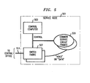
- FIG. 5 shows such a service node 501.
- the components of service node 501 are switch fabric 507, which routes incoming calls to their destinations, common service circuit frames 501 which provide services such as voice prompts and collection of data input by callers, and control computer 503 which controls the operation of switch fabric 507 and common service circuit frames 509. Control computer 503 thus corresponds to control computer 103 of FIG. 1 and switch fabric 507 and common service circuit frames 501 together correspond to device 105.
- Service node 501 is further connected via line 511 to the central office of the telephone company to which node 501 belongs. Line 511 permits remote monitoring and maintenance of service node 501.
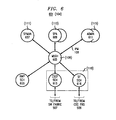
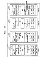
- FIG. 6 is an overview of some of the processes which execute in control computer 501.
- System 601 corresponds to service package system 104 of FIG. 1.
- FIG. 6 portions of FIG. 6 which correspond to portions of FIG. 1 are labelled with the number of the corresponding portion of FIG. 1. The number is enclosed in parentheses.
- the processes communicate by means of inter process messages 108, which are carried by message handler (MSGH) 605.
- message handler MSGH
- SPMAN 607 corresponds to SPM 111; like SPM 111, it maintains a table which relates entity identifiers to services; in the preferred embodiment, however, entity-service table 201 in SPMAN 607 is in memory in control computer 503 which is accessible to processes in system 601 other than SPMAN 607, making it possible for those processes to determine the service corresponding to an entity identifier without sending a message to SPMAN 607.
- Service package applications 609 correspond to service package processes 113 of FIG. 1. In this embodiment, they provide telephone services such as 800 number service, locator service, calling number announcement service, or telephone voting to subscribers to the service. When a subscriber subscribes to the service, he is given a telephone number, and that telephone number serves as entity identifier 205 for the service.
- Administrative (ADMIN) processes 611 correspond to management processes 115, and perform management and maintenance functions for the services.
- the functions include the following in a preferred embodiment:
- USLI User System Language Interface
- OA&M operations, administration, and maintenance
- USL User System Language
- the USLI also supports the Primary Maintenance, Control & Display, Critical Indicators, and Emergency Action Interface channels for both the local and remote maintenance centers.
- the USLI manages the interface between the Control Computer and the Alarm Relay Unit (ARU).
- ARU Alarm Relay Unit
- AMATPI AMATP Interface
- HOC automatic host accounting host collector
- EADASI EADAS Interface
- the EADASI provides the interface between the platform and an EADAS system.
- EADASI performs all necessary functions to transfer measurements data between SN 501 and an EADAS system over a BX.25 link.
- CUSTI Customer Interface
- Billing (BILL) ⁇ The Billing process (BILL) collects billing records generated by executions of services. BILL also generates primary tracer records included in the billing data stored to disk. BILL handles AMA and, other billing records,
- the DB subsystem is the repository for all recent change and provisioning data. It is also responsible for notifying the proper process when an update to the database may affect that process.
- Scheduler (SCHED) ⁇ SCHED is responsible for scheduling processes to run at regular intervals (e.g. diagnostic and audit processes).
- MEAS Measurements
- the Initialization process controls process initialization during all levels of system initialization and monitors system sanity while SN 105 is active.
- ADELOAD ⁇ ADELOAD is responsible for downloading all of the necessary files from the Application Development Environment (ADE) to load new service and device handler applications onto SN 105.
- CSCF SCH 613 controls common service circuit frames 509
- SF SCH 615 controls switch fabric 507.
- RWP SCH 603 is a process which implements "reverse white pages", i.e., a function which, when given a telephone number returns information about the number's subscriber.
- the reverse white pages are implemented in software, but in other embodiments, they may be implemented in special hardware.
- service node 501 Operation of service node 501 is as follows: As mentioned above, telephone numbers serve as unique identifiers for entities subscribing to services provided by service node 501.
- switch fabric 507 When switch fabric 507 receives a call, it provides the called telephone number and the calling telephone number to switch fabric SCH 615, which in turn uses the called telephone number as an entity identifer in entity-service table 201.
- Switch fabric SCH 615 then sends an event message 108 containing the calling number and the called number to service package application 609 for the called number. That service package application 609 responds to the event message by beginning an execution of the service for the called number.
- service package application 609 sends messages to the SCH processes and to the ADMIN processes 611 as required to carry out the services and perform billing and data recording functions.
- Maintenance of service node 501 is performed in the same fashion, except that the maintenance operation is performed by one of the ADMIN 611 processes, which sends messages 108 to the other processes as required to perform the maintenance function.
- SPA 609 is implemented by means of two processes for each service. As is the case with the other processes in system 601, the processes communicate with each other and other non-SPA processes in system 601 by means of messages 108.
- the two processes of SPA 609 divide the functions of SPA 609 according to the source and destinations of the messages they receive and provide.
- Application execution (AEX) process 703 receives messages from and provides them to the SCH processes 603, 613, and 615 and additionally receives messages from and provides them to its corresponding service process 701.
- Service process 701 receives messages from and provides them to SPMAN process 607 and ADMIN processes 611, as well as providing them to and receiving them from AEX 703.
- SP process 701 which will be examined in more detail later is decision graph builder (DGB) 705, which builds the decision graphs 221 traversed by service process 701.
- DGB decision graph builder
- AEX process 703 effectively handles the interface to the hardware devices, while service package process handles the interfact to the other processes.
- SP process 701 and AEX process 703 may be combined into a single process, or there may be a single AEX process 703 which serves the SP processes 701 for all services available on system 601. However, in all cases, there will be a one-to-one relationship between a service and a copy of the code defining the service, and the processes will execute the copy of the code corresponding to the service
- FIG. 8 shows the data used in executing a service in response to a call in SPA 609.
- This data corresponds to service package data 215, and like that data, has parts (802) which are global to all executions of the service, parts (803) which are per-subscriber (i.e., per each of the telephone numbers which are entitled to the service), and parts which are per-individual call (805).
- Correspondences to FIG. 2 are indicated by the numbers in parentheses.
- Global data 802 is available to any call being served by SPA 609;
- per-subscriber data 803 is available to any call for that subscriber being served by SPA 609 and includes any per-subscriber decision graphs 121;
- per-call data contains the state of a current call to the service provided by the subscriber. Per-call data is available only to the current call and is removed at the end of the call.
- SPA Data 801 is subject to frequent change. Subscribers may be added to or deleted from a service, the rate a subscriber is paying for a service may change, new decision graphs may be required, and so forth. Modification of SPA data 801 for a service while the service continues to function is termed provisioning the service.
- provisioning is performed by two of administration processes 611, Customer Interface (CUSTI) , for non-decision graph data, and Decision graph interface (DEGR).
- FIG. 9 shows how these processes employ messages 108 to perform the provisioning.
- Customer interface (CUSTI) 901 permits an employee of the telephone company to which service node 501 belongs to provision a service package from a terminal connected to service node 501.
- CUSTI 901 begins by forking to produce a child process, FORM 903, which displays a form for the data to be added on the terminal. The employee then fills in the form, and FORM process 903 provides the data in the form to SPA 609, which updates per-subscriber data 803 or global data 802 as required. If an update of entity-service table 201 in SPMAN 607 is also required, that is taken care of by messages between SPA 609 and SPMAN 607. FORM process 903 also provides the data to a data base process 907 of administration processes 611, and data base process 907 stores the data in a data base available to service node 501. Storage in the data base assures that the data can be reloaded into service node 501 if there is a failure in control computer 503 and also makes the data available for telephone company record keeping.
- DEGR 905 interacts with decision graph builder component 705 of service process 701 to provide a decision graph 221 for a subscriber to the service executed by service process 701.
- Decision graph 221 in a preferred embodiment is defined by an application programmer using a graphical DG Editor to "paint" a DG that consists of nodes (e.g. time-of-day nodes, day-of-week nodes, connection nodes, announcement nodes, etc.) that are interconnected based on the flexible logic intended by the DG programmer.
- the DG Editor generates a DG Description File 1001 (ASCII text) that describes the DG's characteristics.
- the associated DG Compiler reads the DG Description File, determines whether the DG complies with all of the rules associated with DGs in general and the selected nodes in particular, and then if the DG is valid, prepares a DG Definition File (ASCII text) that provides all of the information that is needed by the DGB to create the decision graph 221.
- ASCII text a DG Definition File
- Figure 10 shows the contents of the DG definition file.
- the definition file includes information that defines each of the DG's Nodes and each of its Tables with one Node or Table defined on each file line.
- a Node's definition includes
- Each table is described by a file line that contains the argument and value pairs that make up the table.
- a table must be defined before it can be used in the definition of a table node.
- the DG can be instantiated within a Service Package.
- DG instantiation can occur as a result of initialization of service process 701, subscriber initialization or subscriber recent change activity (the latter may be recent change activity on the part of the network provider or on the part of the subscriber).
- SP 701 uses a DBselect message 108 to determine what data must be loaded into the SPP; the response to this request will identify the names of all DG Description Files that are associated with the SP 701's DGs.
- the names of the DG Description Files are sent to the SP 701 via a DBformInsert message, and if an existing subscriber's data is changed (the flexible logic associated with a DG changes), the identity of the DG's Description File is provided through a DBformUpdate message.
- SP 701 creates an instance of a C++ DecisionGraph Class.
- Decision Graphs are instances of the class Decision Graph. Each such instance includes a set of node objects (one object per node), and it provides methods for building and traversing the DG.
- DGs are "smart" data objects. DGs are can be created for each DG variable declared within the service package code executed by an SP 701. Because an application programmer can associate such variables with individual subscribers or associate them with all users of the service, the DGs that are created through the DGI can be assigned to individuals or groups of individuals.
- SP 701 Once SP 701 has created an instance of DG, it can instruct the DG to "build" itself by invoking the DG's build function.
- the inputs to the build function are the name of the DG's Description File and a dictionary of valid node types (the contents of this dictionary are based on the application programmer's declaration of valid nodes for the DG variable being defined.)
- the build function stores this information and the current date and time in the DG class member for future use.
- DG The construction of a DG requires communications between SP 210's decision graph builder 705 and DEGR process 905.
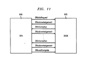
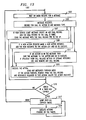
- FIG. 11 shows these communications.
- DGB 705 software employs a simple finite-state machine algorithm to progressively build up a DG by iteratively requesting DG information from DEGR process 905 and then processing it on delivery.
- the actions are the requests for node data sent from DG BUILD 705 to DEGR process 905, and the events are the node definitions that are returned from DEGR 905 to DG BUILD 705.
- Communications between DG BUILD 705 and DEGR 905 are of course by means of messages that are delivered through MSGH 605.
- service process 701 executes a finite state machine in which certain states of the finite state machine may traverse decision graphs 221.
- Decision graphs 221 in the preferred embodiment are implemented as a class of the C++ object programming language. Included in the definition of the decision graph class is a traversal method.
- Required inputs to the traversal method include the call data object 1203 (shown in FIG. 12 infra), which is a part of per-call data 805.
- Call data object 1203 for a call contains all of the run-time (dynamic) data that is associated with the code. It also contains data members that are specific to the traversal of the decision graph 221 service process 701 is currently traversing for the call.
- These members include currentNode, indicating the node of decision graph 221 being traversed, and traverseState, indicating the current state of the traversal.
- currentNode indicating the node of decision graph 221 being traversed
- traverseState indicating the current state of the traversal.
- the traversal method is implemented as a finite-state machine that iteratively asks each member node, beginning with DG 221's root node, to traverse itself and return the identity of the node (child) to which control is next to be passed
- the traversal (or execution) of a member node depends on the type of node that is encountered.
- Decision nodes provide software that examines the value of the affected variables and selects the appropriate branch and child to which control is to be passed.
- the child's identity is placed in the currentNode data member, and the traverseState is set to DR_CONTINUE.
- the node then returns control to the traversal method, which notes that the traverseState implies an immediate continuation and so it calls a method provided by the class for traversing a node of the type of currentNode.
- Some of the node types are predefined; the methods for these nodes are provided as part of the system software for system 601. Hence, the selection of a child is done immediately, and the decision can make use of any data available in calldata object 1203 for the call.
- Nodes that are user-defined require that the logic provided for selecting the child be defined as part of the finite state machine executed by service process 701.
- the node traversal method for user-defined decision nodes therefore cause service process 701 to send an event request to itself.
- the event request specifies a user-defined event handler which service process 701 executes in one of the states of its finite state machine.
- the event handler must select a child and the traversal method continues traversal with the selected child. Because the event handler is executed by SP 701, it has access to SP 701's global, per-subscriber, and per-call data.
- Action nodes are of two types, local and external.
- Local action nodes are nodes that are permitted to change the values assigned to data available to the DG.
- Local action nodes differ from decision nodes only in that they do not choose among different children; instead they have exactly one child to which control will be given once the data values have been set.
- External action nodes are similar to terminating nodes in that they send SP 701 an event message requesting a specific action; they differ from a terminating node in that they are designed to continue the traversal (e.g., selecting a child) after the action has been carried out by SP 701. External action nodes indicate the need to continue traversal by setting the traverseState to DR_WAITING and returning control to the graph traversal method, which itself returns. In this case, the traversal of decision graph 221 can be continued after SP 701 has responded to the event message 108 and completed whatever action was requested in the event message.
- SP 701 specifies what node is to be traversed next and may also set data values used during the traversal of that node. Then SP 701 invokes the traverseContinue method defined for the decision graph class. When this method is invoked, it checks the current value of traverseState (it must be continue) and the value of currentNode. It selects the node specified and invokes that node's traverseContinue method. It is now possible for the node to complete its work, select a child, set the traverseState to DR_CONTINUE, and return control to the graph traversal method.
- SP 701 is not required to continue the traversal of a DG 221 that has sent an event message to SP 701. It is left to the design of the finit state machine executed by SP 701 to make such a determination.
- the methods defined for the decision graph C++ class are fully capable of dealing with a traversal that is discontinued after an external action node has sent an action request to SP 701.
- a DG traversal it is always possible, of course, for a DG traversal to fail. If a node decides that a traversal should be discontinued, it sets the traverseState to DR_FAILED. The graph traversal method detects this failure, and it sends an appropriate failure code (traverseFailed event) back to SP 701.
- the data structures are components of per-call data 805.
- the call data object contains at least the call identifier (usually the telephone number) for the service subscriber and an identifier for a corresponding call record used by AEX 703.
- SP 701 locates call data objects 1203 by means of tables 1205, which map the call identifier to the call data object.
- the data structures 1207 in AEX 703 are similar, except that AEX call record object 1209 contains a pointer to the corresponding call data object 1209. Again, there are tables 1211 permitting location of the call record object corresponding to a call identifier.
- each message from AEX 703 which responds to an action request to AEX 703 from SP 701 contains the call identifier and the pointer to the call data object in SP 701 for the call; similarly, each message from SP 701 to AEX 703 requesting an action includes the call identifier and a pointer to the AEX call record 1209 for the call.
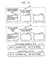
- AEX 703's main processing loop is detailed in FIG. 13.
- the loop appears as loop 1301 in that Figure.
- AEX 703 waits for messages 108 from other processes in system 601.
- service start messages from SF SCH 615 (or in other embodiments from a process in ADMIN 611 or SP 701)
- action request messages from SP 701 SCH message responses from message requests that the AEX has previously sent to the SCH processes
- call related messages from the SCH processes call related messages from the SCH processes
- timer messages timer messages.
- AEX 703 creates an AEX call record object 1209, as shown in block 1307. It adds the call id and the new call record to call id table 1211. AEX 703 then sends a SPterminatingCall" or "SPorginatingCall" message 108 to SP 701, depending on which one is required. AEX 703 puts the AEX call record pointer in this message, so that subsequent action requests can be added to the call record
- AEX 703 creates an action data object.
- the AEX "actionid” is the pointer to the action object, and the "actionid” is passed as a field in all action messages 108 to the SCHs, and must be sent in all responses from the SCHs to AEX 703.
- the action object is added to AEX call record object 1209 for the call.
- AEX 703 then executes the action object by calling its "start" method. The action then can send messages to SCH processes through MSGH 605 and wait for responses.
- AEX 703 decodes the "actionid” from the message and uses it to directly call the "processmessage” method of the action object, as shown in block 1311. The action then processes the message and sends any required requests to the SCHs processes, as shown in block 1313. If this is the last response required by the action, the action is removed from AEX call record data object 1209 for the call, and the action sends SP 701 an action response message. Once the action response message has been sent the action is deleted.
- AEX 703 decodes this message and sends a response to SP 701. If the message has a valid actionid in it, AEX 703 also sends the message to the action as described above.
- the timers in the timer list that have expired are set to an expired state in the signal handler.
- the signal handler checks to see if the process is waiting on the message queue. If the process is waiting on the message queue the signal handler calls the AEX timer method to process the expired timers immediately, otherwise the signal handler sets the expired timer flag. The signal handler then returns. When the message that is being currently processed is finished the timer flag is tested. If a timer has expired, the actions that are pending on that timer are all executed before any more messages are process. The timeout entry for the action is called with a timeout message argument. The action processes the time out using any data in the message that it requires. When all the expired timers have been processed, AEX 703 goes back to waiting for messages 108.
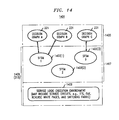
- FIG. 14 shows the kinds of code executed by service process 711 and the relationship of decision graphs 221 to that code.
- Programming architecture 1401 for a service has three levels: decision graphs 221, at level 1407, service finite state machines (SFSM) 1403 at level 1407, and service logic execution environment (SLEE) at level 1409.
- decision graphs 221 are part of service package data 801; finite state machines at level 1407 and SLEE 1409 correspond to service package code 213 in FIG. 2.
- Level 1407 contains one or more finite state machines machine for each service provided by service node 501. Each of the finite state machines responds to some of the events related to the service.
- a given finite state machine 1403 may employ one or more decision graphs 221. The decision graphs may be global, i.e., apply to all users of a service, or may be part of the per-subscriber datat for service process 701.
- the three levels of architecture 1401 further correspond to three levels at which a service may be defined.
- the routines in service logic execution environment 1409 are provided by the manufacturer of service node 501, though they may be modified by the telephone company which uses service node 501.
- the service finite state machines 1403 will generally be provided by the telephone company which uses service node 501, though the manufacturer may provide some services, and in some cases, sophisticated subscribers to services may provide finite state machines 1403.
- the decision graphs 221, finally, may be provided by the telephone company, or in many cases by the subscribers.
- Architecture 401 thus allows each party involved in defining a service to define the level for which the party has the expertise and information and further insulates each level from the effects of changes in the higher levels.
- each level employs its own coding techniques.
- the techniques used at a level correspond to the expected degree of expertise of the persons doing the programming.
- SLEE 1409 is produced by experienced systems programmers; consequently, the language used at that level is C++.
- the service finite state machines 1403 of level 1407 will generally be produced by experienced applications programmers; consequently, the language used at that level is an application-oriented language called service logic language (SLL).
- SLL permits the programmer to directly describe a finite state machine.
- the decision graphs 221 at level 1405, finally, will be produced by subscribers or also by telephone company craft people engaged in provisioning service node 501.
- producers of decision graphs 221 are provided with a graphical user interface which allows the producer to directly specify a decision graph on a graphics terminal.
- specification of a decision graph on a graphics terminal results in the production of a graph definition file 1001, from which an instance of a C++ decision graph type is produced when the service is provisioned with the graph in graph definition file 1001.
- an SLL compiler With regard to code written in SLL, an SLL compiler generates C++ code from the SLL code.
- the C++ code specifying the decision graph type, state machine 1403, and SLEE 1409 is then compiled to produce the executable code required by the processor upon which service process 701 is executing.
- service finite state machine 1403 for a service is executed by service process 701, while the service logic execution environment code 1409 for the service is executed for the most part by AEX 703 corresponding to service process 701.
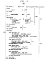
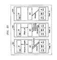
- FIG. 15 Defining a System Finite State Machine 1403 in SLL: FIG. 15
- FIG. 15 shows a SLL program 1502 which defines a system finite state machine 1501.
- Finite state machine 1501 has a single state, in which it responds to a telephone number by playing an announcement.
- SLL program 1502 has two major parts: data declarations 1507 and state sequence 1515. Beginning with data declarations 1508, finite state machine 1501 has no static data 801; per-subscriber data 803 consists of the following:
- SLL statements may occur within an event handler.
- the first are conventional statements, such as assignment ( set and reset statements), two way branch ( if statement), multi way branch (test statement), and table manipulation ( search, loop, insert, and delete statements).
- the second are service specific statements such as traversing a decision graph ( traverse and traverse ⁇ continue statements), scheduling an event for some time in the future (schedule statement), and invoking actions that interact with the SCH processes.
- An example is the tts!send statement in program 1502, which causes a text message to be converted into speech and sent to the caller.
- the third kind is statements which transfer control between event handlers and between states.
- next ⁇ state statement transfers control to a state named in the statement, while the next ⁇ event statement does the same with regard to a named event handler in the state containing the statement.
- the actions that are invoked with names such as tts!send are implemented in library routines which are compiled into the code executed by AEX 703 corresponding to the service process 701 executing the state machine.
- SLL includes basic data types, such as flags, numbers, and strings and many data types that are telephony specific such as ports, per subscriber tables with per call indexes, and decision graphs.
- SLL supports extensive data update capabilities that allow the programmer to specify the data update properties a data variable should have (e.g., static, dynamic, recent changeable, or measurements), and the SLL compiler takes care of implementing the details to fulfill those properties.
- the maintenance personnel and service users perform recent changeable data updates through a common forms interface. Default forms for recent change are automatically generated by the compiler based on the programmer's declarations.
- FIG. 1601 is a fragment 1601 of SLL code which has more than one state. Each state is defined by a state block 1615 which is bracketed by "state ⁇ name> -- end state ⁇ name>". When executed, "next state" statement 1611 causes a transition from the state in which the statement occurs to the state specified in the statement.
- FIG. 16 further shows how the traversal of a decision graph 221 is specified in an SLL program and how a SLL program may define an action which results from the traversal of a user-defined node of decision graph 221.
- the declaration 1604 "Graph1" in rc data 1509 declares a per-subscriber decision graph of that name. The graph is shown at 1607 in the figure.
- the action statement "dg!traverse Graph1" 1609 specifies that "Graph1" is to be traversed at that point in the execution of the event handler 1517 for "terminating_call".
- Graph1 1607 has three nodes: a system-defined "day” decision node which chooses among the branches depending on the time of day, and two terminal nodes, one, connect, which is system-defined and which, when traversed, connects the caller to a telephone number specified in the node's data and then returns an event message to service process 201 executing the SLL program, and another, TTS_final, whose action when traversed is user-defined, and consequently must have an event handler in code 1601.
- TTS_final node is specified as a leaf node with a user-defined action in declaration 1603.
- node specifies that TTS_final belongs to the class of decision graph nodes and "terminate” specifies that it is a leaf node within that class.
- Text string indicates that when the node is traversed, an event record resulting from the node traversal will contain a string value.
- Event handler 1613 has the name of the TTS_final node and is thereby identified as the event handler which will be executed by service process 701 when traverse action 1609 is executed and the traversal ends at the TTS_final node.
- the result of the traversal of the node is the sending of an announcement.
- the expression "text TTS_final.Text” indicates that the text used for the announcement will be that specified in the event record produced when TTS final was traversed.
- FIG. 17 shows the output from a preferred embodiment of SLL compiler 1707 when it compiles SLL source 1701.
- the C++ code for SFSM 1403 is shown at 1703; the remaining outputs all belong to system characterization code 1705. Included among them are:
- FIG. 18 shows debugging system 1801 used to debug a service.
- a base debugging process 1803 is created in SPA 1609 in addition to the SP and AEX processes.
- the debugging process 1803 communicates by means of messages 108 with a debugging process in administration processes 1805, which in turn provides debugging information to and receives debugging information from a terminal being used by the programmer doing the debugging. Additionally, debugging process 1803 communicates by means of debugging messages 108 with service process 701 which is executing the SLL code being debugged.
- the debugger used in debugging system 1801 is an application level debugger that allows Service Packages that are written in the Service Logic Language (SLL) to be debugged in the context of the SLL code, rather than the generated C or C++ code. Because application programmers work at the SLL source level, those programmers do not have to understand the C or C++ code that is generated by the SLL compiler.
- SLL Service Logic Language
- SLL programmers can set, release, enable, or disable breakpoints for SLL line numbers, event handlers, or state transitions. It is possible to qualify a breakpoint using Boolean expressions. Since the debugger operates at the SLL level, data is displayed and accessed in terms of the SLL program. If a user needs to access any other data items (e.g., stack backtrace data), the application level debugger accepts commands for the underlying C/C++ debugger that is provided by the control computer vendor. Data dumps can be viewed on the screen or directed to an output file.
- data items e.g., stack backtrace data
- the SLL debugger also allows the application programmer, when testing, to send events via BDP 1803 to the Service Package that is being debugged. These event reports can contain the data that would be provided if the event were delivered from service node 501 to the application program.
- the programmer can test the software that designed to respond to an event such as a disconnect by generating a disconnect report through the debugger.
- the user interface for the interactive application level debugger is both graphical and textual.
- the graphical interface is Open LockTM compatible.
- the SLL source code can be viewed on the screen, and tracing can be turned on so that program statements are highlighted as they are executed.
- When used in the non-interactive mode only the textual interface is supported.
- the text interface is curses based and can be used on any terminal.
- a command language is provided to allow a user to perform the features described above. It also allows a user to save a debugging session in a file and to restart a session from a certain point. This file can be edited.
- a mouse based graphical interface can be used in the interactive mode.
- the SLL programmer can establish breakpoints that trigger when events from the DBGI process arrive at the SP.
- the debugger also allows the programmer to create events and inject them into the Service Package that is being debugged to check the robustness of the package.
- the SLL debugger can be used on the programmer's workstation to debug an SP process 701.
- nodes there are three categories of nodes:
- FIG. 20 shows a decision graph 221 which routs a call during business hours to an office in a location which is determined by the caller's zip code and which provides messages to the caller outside business hows.
- the representation of the decision graph in FIG. 20 is substantially the same as that which appears to a person creating or editing the decision graph using the decision graph editor which is provided as part of system 601.
- Root node 2002 indicates the point at which a traverse of decisiong graph 2001 is to begin; node 2003 is a system-defined day of week decision node; node 2007 is a system-defined time of day decision node; nodes 2005 and 2009 are system-defined announce final nodes.
- Get-zip node 2011 is a user-defined action node whose traversal results in the execution of an event in service finite state machine 1403 for the service. In executing the event, finite state machine 1403 sends an action message 108 to its AEX 703 to which AEX 703 responds by sending an action message 108 to reverse white pages SCH process 603 which provides the caller's telephone number.
- process 603 returns a message 108 to AEX 703 which either contains the zip code or indicates that process 603 failed to find one.
- AEX 703 then provides a message with the same contents to finite state machine 1403.
- Finite state machine 1403 has event handlers for both a message 108 containing the zip code and a message 108 which does not contain the zip code.
- the event handler for the message with the zip code places the zip code in a viable for the call and executes the traverse continue statement specifying the branch to node 2017.
- the event handler for the message without the zip code executes the traverse continue statement specifying the branch to node 2014, which is a system-defined connect node which connects the caller to a number in Kansas. Completion of the connection of course completes the traversal of the graph.
- variable containing the zip code is used in system-defined table translation node 2017 to select one of three branches. Two of the branches end in system-defined connect nodes 2019 and 2021; the third branch leads to a system-defined percent decision node which directs fixed percentages of the calls to the branches ending in connect nodes 2025 and 2027 respectively. Again, completion of connections by the connect nodes completes the traversal of the graph.
- Figure 21 shows an example of the graphical interfaces used to define nodes in the decision node editor.
- Window 2101 is the window used to define a prompt, collect, and validate action node. Similar windows exist for each of the system-defined node types, as well as for user-defined node types.
- the data necessary to define the node's action is entered in fields in the window.
- Field 2103 receives the name of the node; the fields in 2105 define the prompts used to obtain the information.
- an initial prompt and a retry prompt are defined, along with the number of retries which are to be made.
- Pop-up menus are further available which show what options are available for the field.
- the fields in section 2107 indicate what kind of data is to be collected.
- Buttons 2112, 2113, and 2115 at the bottom of window 2101 permit the user of the editor to cancel his entries (button 2112), verify the correctness of the node (button 2113) by invoking a verification program which check the node for consistency with other portions of the decision tree and the SLL program for the finite state machine 1403 which will traverse the decision tree, and to finish the node (button 2115) by verifying it and if it passes, closing window 2101 and displaying the newly-defined node on the terminal. The new node can then be moved to the proper branch of the tree and linked in.
- SPA 609 has several interfaces that exist between the components of SPA 609. There is a message interface between SP 701 and AEX 703, a message and data interface between SP 701 and DGB 705, and a set of messages that SP 701 sends to itself. These interfaces are discussed below. The interface between the SLL debugger and SP 701 is discussed in the "External Interfaces" section.
- Sent by SP 701 to AEX 703 to answer the call contains a call id, an AEX call record id, and a port number (HWid,CRV).
- the message contains a call id, an AEX call record id, and a DN.
- the message contains a call id, an AEX call record id, and a character string. This is an internally generated message not available at the SLL language level, that is used for alarms.
- the string in this message can be sent to the logging process.
- the message contains a call id, an AEX call record id, and a character string.
- the message contains the call id, an AEX call record id, and a port number (HWid,CRV).
- AEX 703 ignores the CRV value and only uses the HWid. If the port that is released is part of a connected path the path is broken before the port is released.
- the message contains the call id, and SP 701 calldata id.
- This message contains the call id, an AEX call record id, a port number (HWid,CRV) for A party and a port number (HWid,CRV) for B party.
- This message contains the call id, an AEX call record id, the port number (HWid,CRV) (BRI port from the CO) and a character string of text to play on the port.
- This response indicates that the alerting message has been received on the BRI port and that the phone is ringing.
- the message contains the call id, the calldata id, the terminating port number and the terminating DN.
- the message contains the call id, the calldata id, the terminating DN, and two status strings for the two call appearances, and a reason string that describes the reason for the failure.
- the call may be returned to the state that it had before the command was performed.
- This message indicates that the calls have been successfully transferred back to the CO (central office).
- the message contains the call id, the calldata id, and the port number (HWid,CRV).
- the message contains the call id, the calldata id, the terminating DN, and two status strings for the two call appearances, and a reason string that describes the reason for the failure.
- the call may be returned to the state that it had before the command was performed.
- This message indicates that the call associated with the specified port has been answered.
- the message contains the call id, the calldata id, the port, the DN that answered, and a time stamp (seconds).
- This message indicates that the call associated with the specified port has timed out waiting for answer.
- the port is released by AEX 703.
- the message contains the call id, the calldata id, the called DN and the port.
- the message contains the call id, the calldata id, and the port number.
- This message indicates that a disconnect was detected on the specified port.
- the message contains the call id, the calldata id, the port number (HWid,CRV) and a time stamp used for billing purposes.
- This message returns the name and address associated with the specified DN.
- the message contains the call id, the calldata id, the DN, a name character string and an address character string.
- This message is sent from AEX 703 to SPA 609 when AEX 703 has completed releasing all the resources that it is managing for SPA 609.
- This message indicates that the SN has received a call from a service subscriber on a terminating port.
- the message contains the call id, the calldata id, the originating DN, the dialed digit string (called number), the redirecting number (null if not available) and the port number (HWid,CRV).
- This message indicates that the text-to-speech peripheral has completed playing speech to the specified port.
- the message contains the call id, the calldata id, and the port number (HWid,CRV).
- This message indicates that the attempt to convert the text-to-speech and play the speech to the specified port failed for the specified reason.
- the message contains the call id, the calldata id, a port number (HWid,CRV), and a reason character string.
- This message indicates that the attempt to transfer the calls of party A and party B was successful.
- the message contains the call id, the calldata id, and the two port numbers (HWid,CRV) for the parties transferred.
- This message indicates that the attempt to transfer the calls of party A and party B failed.
- the message contains the call id, the calldata id, two port numbers (HWid,CRV), two status strings and a reason character string.
- the message describes which DG is to be traversed and for which active call.
- the message describes which DG is to be continued, for which active call and for which branch.
- This message is sent to the SPA when it is time to report some measurements to the MEAS subsystem.
- the message describes which measurements should be sent.
- This message indicates a start_timer() action has expired without a corresponding stop_timer() having been done. It has a field that describes the call that started the timer.
- This message means a schedule statement has expired.
- the message includes the DN of the customer that started the schedule, and arbitrary user data.
- SP 7016 When performing a long task, SP 7016 will send itself SPsplit messages to break up the task.
- Each of the messages described below is derived from the Message Handler message class that is used as a base class for all messages and thus includes the data for the base class.
- This base class contains data for priority type, a message type and the senders message QID. If an SPA 609 receives a message it does not understand, it will make a Craft log entry about the message and ignore the message.
- SPA 609 will use MSGH 605 for creating its input message queue and for finding the input message queues of all other processes with which SPA 609 needs to communicate.
- This message tells SPA 609 that SPMAN 607 to start an audit of the DN routing tables.
- SPA 609 will send a few (around 20) ReRegister messages to SPMAN 607 and then send itself an SPsplit message (see above) to give Call Processing messages a chance to be processed. After all ReRegister messages have been sent, SPA 609 will send the SPauditAck message to SPMAN 607 tell it this SPA is done with the audit.
- An exit can be either conditional or unconditional.
- SPMAN 607 sends this message to SPA 609, it has arranged that no more call will route to this SPA.
- a conditional exit tells SPA 609 to wait for all active calls to finish.
- SPMAN 607 wants to know if the SPA is sane. When SPA 609 is operating correctly, it will respond with another SAspSan message back to SPMAN 607.
- SPA 609 registers a DN (especially when a Form has changed an access DN) it wants to know if SPMAN 607 has accepted the new DN.
- the SAsubRegAck message is sent to SPA 609 from SPMAN 607 when a register is successful and an acknowledgement was requested in the register message.
- SPMAN 607 keeps track of the Directory Numbers (DNs) that route to each SPA.
- SPA 609 may ask SPMAN 607 to update these tables so that either new customers start to route or that former customers no longer route to SPA 609.
- SPMAN 607 If SPMAN 607 detects that SPA 609 is not functioning, (either because SPA 609 core dumped or the SPA does not respond to sanity messages) SPMAN 607 will kill the existing SPA, and start a new one.
- SPA 609 determines that it is overloaded (so that all customers are getting poor service) it can tell SPMAN 607 it is overloaded, and SPMAN 607 will stop routing new calls to SPA 609. (These calls will be rejected, on the philosophy that it is better to give good service to most and reject a few, than to give bad service to all.) Once SPA 609 feels it is not overloaded anymore, it will tell SPMAN 607 to resume routing new calls to SPA 609.
- SPA 609 uses an SPMAN 607 function to access SPMAN 607's shared memory tables to check that the DNs stored in the table match the customer DNs for SPA 609. SPA 609 then sends SPMAN 607 messages to correct any discrepancies.
- An SPA can send to SPMAN 607 the SAspDebug message to tell SPMAN 607 that this SPA is being debugged. While being debugged, SPMAN 607 will still route calls to the SPA but SPMAN 607 will neither audit SPA 609 nor send it sanity check messages.
- DB is sending the results of a DBselect request back to SPA 609
- SPA 609 After a reboot, SPA 609 needs to read all of the customer data for SPA 609 from the DB tables of the SPA. SPA 609 send a DBselect message to DB for each table SPA 609 maintains. The DBselectAck messages from DB are used to populate SPA 609 in-memory data structures.
- the following messages are sent from a DB Form to an SPP.
- SP 701 when a form changes the routing information for a customer of an SPA, SP 701 will register the change with SPMAN 607 and request an acknowledgement (ACK) back from SPMAN 607. Once SP 701 gets this ACK, it will send the ACK to the DB. If the change does not affect customer routing information, SP 701 will simply record the change and send an ACK back to the form (which should then record the change in the DB).
- ACK acknowledgement
- a form has changed a tuple in a DB table (for this SPA).
- This message to SPA 609 contains a description of the changes.
- a DBformUpdate that modifies a SLL table will fail if that table entry is presently "empty”.
- the DBformInsert message is used to add customers to an SPA and add routes to SLL tables.
- An insert for a customer may possibly invoke interaction with SPMAN 607 or the decision graph reader. The response to the form will not be sent until these interactions are completed.
- SP 701 When an insert into an SLL table succeeds, SP 701 will send the table index allocated back to the DB form. Sending the index from SP 701 to the DB form saves the DB form from having to search the entire DB table for an unused table index.
- the DBformDelete message is used to remove customers from an SPA or remove routess from SLL tables. If this customer has any active schedule requests pending, they will be canceled. If the customer being deleted has an active call, that call will continue but no new calls will be started. Even if a call is up, the routing information for that customer will be removed from SPMAN 607's routing tables.
- TTS SCH test to speech
- the messages described below are a subset of all the messages that 401 be accepted by the SPA 609.
- This message informs SPA 609 that the allocation of a TTS port was successful.
- the message contains an action identifier, a call identifier, a hardware number of the text-to-speech port, a time stamp of when the tts port was allocated, and a hardware number of the associated Switch Module port.
- This message informs SPA 609 that the TTS SCH does not understand the previous message, or that a request has failed.
- the TTS SCH sends back the action identifier and the call identifier in the message and the type of the message that failed, and a reason code.
- This message informs SPA 609 that the TTS port has been deallocated.
- the message contains an action identifier, a call identifier, a time stamp of when the tts port was deallocated, and a hardware number of the text-to-speech port.
- This message informs SPA 609 that the text that was sent in a previous TTsendText message was played on the specified port.
- the message has an action identifier, a call identifier, a hardware number of the text-to-speech port and a time duration for the time that it took to play the speech.
- This message informs SPA 609 that the text that was sent in a previous TTsendText message failed.
- the message has an action identifier, a call identifier, a hardware number of the text-to-speech port, a time duration for the time that was used on the resource before the failure occurred, and a reason string.
- This section describes the messages that are sent from SPA 609 to the TTS SCH.
- This message requests that the TTS SCH allocate a TTS port to SPA 609.
- This message contains an action identifier and a call identifier and a hardware number.
- This message is used by SPA 609 to release the specified port from the TTS SCH's busy list and make it available again.
- the message contains an action identifier, a call identifier, and a hardware number for a TTS port.
- This message is used by SPA 609 to send a set of text to the TTS SCH and have it played out a TTS port.
- the message contains an action identifier, a call identifier, a hardware number for a TTS port, and a boolean flag that indicates if there is more text associated with this command.
- the messages described below are a subset of all the messages that will be accepted by the SPA 609 from SF SCH 615 and the Line Interface Handler (LIH).
- the SF messages are prefixed with the letters SC or SM and the LIH messages are prefixed with the letters LI.
- This message informs SPA 609 that the call has been accepted.
- the message contains an action identifier, a call identifier, the hardware number of the port, a time stamp, and a call reference number.
- This message informs SPA 609 that SF SCH 615 failed to accept the call.
- the message contains an action identifier, a call identifier, the hardware number of the port, a time stamp, a call reference number, and a failure return code.
- This message is sent to SPA 609 to inform it that alert has been received by the BRI handler.
- the message contains an action identifier, a call identifier, the hardware number of the port that is being referenced, a time stamp, and the call reference number of the port.
- This message is sent to SPA 609 to inform it that the call has been answered successfully.
- the message contains an action identifier, a call identifier, the hardware number of the port that is being referenced, a time stamp, and the call reference number of the port.
- This message is sent to SPA 609 to inform it that the call has failed to be answered.
- the message contains an action identifier, a call identifier, the hardware number of the port that is being referenced, a time stamp, and the call reference number of the port and a failure code.
- This message is sent to SPA 609 to inform it that the call is continuing and to give SPA 609 the call reference number associated with the call.
- the message contains an action identifier, a call identifier, the hardware number of the port that are being referenced, a time stamp, and the call reference number of the call.
- This message is sent to SPA 609 to inform it that the setup has failed.
- the message contains an action identifier, a call identifier, a time stamp, the hardware number of the port that are being referenced, and a failure return code.
- This message is sent to SPA 609 to inform it that the call has been disconnected.
- the message contains an action identifier, a call identifier, the hardware number of the port that is being referenced, a time stamp, and the call reference number of the port.
- This message is sent to SPA 609 to inform it of the call reference value that is currently active.
- the message contains an action identifier, a call identifier, the hardware number of the port that is being referenced, a time stamp, and the new active call reference number of the port. If the call reference value is 0 then no call reference is active.
- This message is sent to SPA 609 to inform it of the select message failed.
- the message contains an action identifier, a call identifier, the hardware number of the port that is being referenced, a time stamp, and the call reference number of the port and a failure return code.
- This message is sent to SPA 609 when a new call arrives at the SN.
- the message contains a call identifier, the hardware number of the port that is being referenced, a time stamp, the call reference number of the port, the customer tag, the service key (redirecting DN), the calling number and the called number.
- This message is sent to SPA 609 to inform SPA 609 that the transfer has succeeded.
- the message contains an action identifier, a call identifier, the hardware number of the port, a time stamp, (for knowing when the call was taken back by the Central office), and the call reference numbers for the BRI ports.
- This message is sent to SPA 609 to inform SPA 609 that the transfer has failed.
- the message contains an action identifier, a call identifier, the hardware number of the port, a time stamp, (for knowing when the call was taken back by the Central Office), the call reference numbers for the BRI ports and a failure return code.
- This message is sent to SPA 609 to inform it that the call has been connected as requested.
- the message contains an action identifier, a call identifier, the four hardware numbers of the ports that were connected, and a time stamp.
- This message is sent to SPA 609 to inform it that the connection request has failed.
- the message contains an action identifier, a call identifier, the four hardware numbers of the ports that were involved, a time stamp and a failure return code.
- This message is sent to SPA 609 to inform it that the call has been disconnected as requested.
- the message contains an action identifier, a call identifier, the four hardware numbers of the ports that were connected, and a time stamp.
- This message is sent to SPA 609 to inform it that the connection request has failed.
- the message contains an action identifier, a call identifier, the four hardware numbers of the ports that were involved, a time stamp and a failure return code.
- the section below describes the messages that are sent from SPA 609 to SF_CH 615 SCH and to the Line Interface Handler (LIH).
- LIH Line Interface Handler
- This message requests that SF SCH 615 accept the call from the Central Office.
- the message contains an action identifier, a call identifier, the hardware number of the port, and a call reference number.
- This message requests that SF SCH 615 answer the call on the given port.
- the message contains an action identifier, a call identifier, the hardware number of the port, and a call reference number.
- This message is used to connect two half connections in SF_SCH 615.
- the message contains an action identifier, a call identifier, and four hardware numbers.
- This message releases the port to be put on the available list of resources.
- the message contains an action identifier, a call identifier, four hardware numbers, and a call reference number.
- This message is used by SPA 609 to select the active call appearance. LIselect with a call reference value of 0 puts the active call on hold.
- the message contains an action identifier, a call identifier, a hardware number of the port, and the call reference number that is to be active.
- This message is used by SPA 609 to generate a call on a BRI port to the central office.
- This message contains an action identifier, a call identifier, an originating Directory Number (DN), a terminating DN, and a hardware number that corresponds to a BRI port. If BRI hardware number already has a call active on it SF SCH 615 will put this call on the same BRI. This is done if SPA 609 is eventually going to transfer the calls on the BRI back to the central office.
- This message drops the call on the port.
- the message contains an action identifier, a call identifier, the hardware number of the port, and a call reference number.
- This message is used to transfer a call from the SN back through the central office.
- the message contains an action identifier, a call identifier, the hardware number of the port that is involved, and the two call reference numbers for the port.
- the two calls that use the hardware number are transferred to being directly connected through the central office.
- the interface between SPA 609 and RWP SCH 603 is described below. This interface may be implemented in the AEX process itself or in a separate process.
- the messages described below are a subset of all the messages that will be accepted by the SPA 609 from RWP SCH 603.
- This message returns the white pages database record to SPA 609.
- the message contains an action identifier, a call identifier, and the database record in name value pair format. If any or all fields are not there in the database, then null values are returned in the message.
- This message is used by SPA 609 to retrieve a white pages database record using the given directory number as a key.
- the message contains an action identifier, a call identifier, and the directory number that is used as the database key.
- This message goes to a craft log maintained by a process in ADMIN 611 and will be used to record any useful debugging information.
- the message contains a string of characters that are to be printed on the log.
- SPA 609 will record all unexpected situations in the log using this message.
- the tester has the ability to turn on and turn off debugging output on an SPA basis using a craft command.
- the service is Area Number Calling (ANC), a locator service designed for a subscriber who has a set of service locations for example, pizza restaurants, spread over a wide area.
- a caller calls one number anywhere in the area, and his/her call is routed to the service location nearest him/her.
- the caller's location (such as zip code) is found using the calling number and a white pages database, and then a table accessible to SP 701 is used to map that location to the nearest service location.
- the service uses a decision graph to decide on the actual customer number to call, and uses the Text-To-Speech SCH of CSCF SCH 615 to provide announcements as well as using SF SCH 615 and RWP SCH 603.
- each frame shows the messages 108 exchanged at that point in the execution of the service between SP 701, AEX 703, and RWP SCH process 603, SF SCH process 615, and TTS SCH of CSCF SCH 613.
- the messages shown being exchanged between DGB 705 and SP 701 in frame 4 2207 are to be understood as messages sent by SP 701 to itself in the course of traversing a decision graph 221.
- FIG. 22 Frames 2201 to 2207
- FIG. 20 shows the first four frames of the scenario.
- FIG. 23 Frames 2301 to 2307
- FIG. 23 shows the next four frames of the scenario.
- FIG. 24 Frames 2401 through 2407
- FIG. 24 shows frames 2401 through 2407 of the scenario.
- FIG. 25 Frames 2501 through 2505
- FIG. 25 shows the last three frames of the scenario.
- control processor may be implemented using many small computers, and a process which corresponds to a service may execute by itself on a single one of such processors.
- a system 104 or 601 may involve processes other than those disclosed herein and the arrangement of processes used to execute a service may vary from that disclosed herein. For example, in some embodiments, no special message handling process may be required, and in others, the SP process and the AEX process may be combined in a single process or a single system AEX process may serve all of the SP processes.
Landscapes
- Engineering & Computer Science (AREA)
- Computer Networks & Wireless Communication (AREA)
- Telephonic Communication Services (AREA)
- Mobile Radio Communication Systems (AREA)
- Stored Programmes (AREA)
- Computer And Data Communications (AREA)
- Exchange Systems With Centralized Control (AREA)
Applications Claiming Priority (2)
| Application Number | Priority Date | Filing Date | Title |
|---|---|---|---|
| US07/672,065 US5640319A (en) | 1991-03-18 | 1991-03-18 | Switch control methods and apparatus |
| US672065 | 1991-03-18 |
Publications (2)
| Publication Number | Publication Date |
|---|---|
| EP0505092A2 true EP0505092A2 (fr) | 1992-09-23 |
| EP0505092A3 EP0505092A3 (en) | 1994-05-11 |
Family
ID=24697016
Family Applications (1)
| Application Number | Title | Priority Date | Filing Date |
|---|---|---|---|
| EP19920302141 Withdrawn EP0505092A3 (en) | 1991-03-18 | 1992-03-12 | Switch control methods and apparatus |
Country Status (4)
| Country | Link |
|---|---|
| US (1) | US5640319A (fr) |
| EP (1) | EP0505092A3 (fr) |
| JP (1) | JPH06253019A (fr) |
| CA (1) | CA2062107C (fr) |
Cited By (14)
| Publication number | Priority date | Publication date | Assignee | Title |
|---|---|---|---|---|
| WO1996029830A1 (fr) * | 1995-03-22 | 1996-09-26 | British Telecommunications Public Limited Company | Fourniture de services dans un reseau de telecommunications |
| WO1997038536A2 (fr) * | 1996-04-10 | 1997-10-16 | Dsc Telecom L.P. | Procede et systeme de traitement d'appel programmable |
| WO1997048239A2 (fr) * | 1996-06-13 | 1997-12-18 | Northern Telecom Inc. | Unite de commande de service utile pour effectuer le traitement de commande d'appels |
| WO1997048240A2 (fr) * | 1996-06-13 | 1997-12-18 | Northern Telecom Inc. | Architecture de service programmable pour le traitement de commande d'appels |
| WO1997048238A2 (fr) * | 1996-06-13 | 1997-12-18 | Northern Telecom Inc. | Noeud de service programmable destine au traitement de commande d'appels |
| WO1998004091A2 (fr) * | 1996-07-19 | 1998-01-29 | Telefonaktiebolaget Lm Ericsson | Validation de procedures |
| EP1079318A2 (fr) * | 1999-08-20 | 2001-02-28 | Fujitsu Limited | Système de traitement de messages |
| US6243453B1 (en) | 1996-07-17 | 2001-06-05 | Alcatel Usa Sourcing, L.P. | Programmable call processing system and method |
| US6282202B1 (en) | 1994-10-24 | 2001-08-28 | Telefonaktiebolaget Lm Ericsson (Publ) | Method for internal communication in a telecommunications system |
| US6487676B1 (en) | 1996-07-19 | 2002-11-26 | Telefonaktiebolaget Lm Ericsson (Publ) | Validation of procedures |
| FR2836617A1 (fr) * | 2002-02-28 | 2003-08-29 | Cit Alcatel | Procede d'affectation de ressources variables dans le temps pour assurer des services continus et application de ce procede a la planification d'un systeme de telecommunication |
| EP1650984A1 (fr) * | 2004-10-21 | 2006-04-26 | Hewlett-Packard Development Company, L.P. | Algorithme de traitement d'appel associé à un numéro de téléphone |
| EP1650985A1 (fr) * | 2004-10-21 | 2006-04-26 | Hewlett-Packard Development Company, L.P. | Algorithme de traitement d'appel associé à un numéro de téléphone |
| WO2007087804A1 (fr) * | 2006-02-03 | 2007-08-09 | Teles Ag Informationstechnologien | Procédé de modification du fonctionnement d'une plateforme de groupes de communication techniques (tkgp) d'un réseau de télécommunication (réseau tk) |
Families Citing this family (32)
| Publication number | Priority date | Publication date | Assignee | Title |
|---|---|---|---|---|
| US6385312B1 (en) * | 1993-02-22 | 2002-05-07 | Murex Securities, Ltd. | Automatic routing and information system for telephonic services |
| JP2968690B2 (ja) * | 1994-07-26 | 1999-10-25 | 日本電気エンジニアリング株式会社 | 交換付加サービス用ソフトウェアの開発方法及び装置 |
| JP2766224B2 (ja) * | 1995-07-26 | 1998-06-18 | 日本電気通信システム株式会社 | 番号翻訳データベース更新方法 |
| GB9603582D0 (en) | 1996-02-20 | 1996-04-17 | Hewlett Packard Co | Method of accessing service resource items that are for use in a telecommunications system |
| US5933645A (en) * | 1996-03-19 | 1999-08-03 | Oracle Corporation | Non-invasive extensibility of software applications |
| US5901214A (en) | 1996-06-10 | 1999-05-04 | Murex Securities, Ltd. | One number intelligent call processing system |
| US6122345A (en) | 1996-06-25 | 2000-09-19 | Mci Worldcom, Inc. | System and method for developing and processing automatic response unit (ARU) services |
| US6366663B1 (en) * | 1997-07-21 | 2002-04-02 | Mci Communications Corporation | System for achieving local number portability |
| US6295351B1 (en) * | 1998-04-23 | 2001-09-25 | Bellsouth Intellectual Propety Corporation | System and method for invocation of a check of a telecommunications application through use of a call probe |
| US6556996B1 (en) * | 1998-07-15 | 2003-04-29 | Ameritech Corporation | Service package application and a service activation manager for use with a service control point in an advanced intelligent network |
| US6253112B1 (en) * | 1998-09-17 | 2001-06-26 | Lucent Technologies Inc. | Method of and apparatus for constructing a complex control system and the complex control system created thereby |
| US6330318B1 (en) * | 1998-09-25 | 2001-12-11 | Mci Worldcom, Inc. | Method of and system for interrupting and parking calls in a switched telecommunications network |
| US6411955B1 (en) * | 1998-12-29 | 2002-06-25 | At&T Corp. | Method and apparatus for providing service announcements |
| US6609205B1 (en) * | 1999-03-18 | 2003-08-19 | Cisco Technology, Inc. | Network intrusion detection signature analysis using decision graphs |
| US6366655B1 (en) | 1999-08-23 | 2002-04-02 | Ameritech Corporation | Method and system for service control point billing |
| US6597957B1 (en) * | 1999-12-20 | 2003-07-22 | Cisco Technology, Inc. | System and method for consolidating and sorting event data |
| US20050195743A1 (en) * | 2000-04-03 | 2005-09-08 | P-Cube Ltd. | Real time charging of pre-paid accounts |
| WO2003024075A1 (fr) * | 2001-09-07 | 2003-03-20 | Truetel Communications, Inc. | Convergence et acheminement de service slee |
| US20030126234A1 (en) * | 2001-11-20 | 2003-07-03 | P-Cube Ltd. | Apparatus, method, and software for analyzing network traffic in a service aware network |
| US7844688B2 (en) * | 2001-11-20 | 2010-11-30 | P-Cube Ltd. | Apparatus, method, and software for analyzing network traffic in a service aware network |
| WO2003093988A1 (fr) * | 2002-05-03 | 2003-11-13 | Cedar Point Communications, Inc. | Procedes de developpement et de description de services |
| US7240068B2 (en) * | 2002-09-06 | 2007-07-03 | Truetel Communications, Inc. | Service logic execution environment (SLEE) that is running on a device, supporting a plurality of services and that is compliant with a telecommunications computing standard for SLEES |
| US6968291B1 (en) * | 2003-11-04 | 2005-11-22 | Sun Microsystems, Inc. | Using and generating finite state machines to monitor system status |
| EP1780974A1 (fr) * | 2005-10-26 | 2007-05-02 | Hewlett-Packard Development Company, L.P. | Réalisation améliorée de communication |
| US8087036B2 (en) * | 2007-08-08 | 2011-12-27 | International Business Machines Corporation | Using an event manager to effect a library function call |
| US7996520B2 (en) | 2007-09-19 | 2011-08-09 | Cisco Technology, Inc. | Behavioral classification of communication sessions using active session initiation |
| US8238538B2 (en) | 2009-05-28 | 2012-08-07 | Comcast Cable Communications, Llc | Stateful home phone service |
| US20110093099A1 (en) * | 2009-10-16 | 2011-04-21 | Newport Controls | Controller system adapted for spa |
| US8789058B2 (en) * | 2011-03-25 | 2014-07-22 | Oracle International Corporation | System and method for supporting batch job management in a distributed transaction system |
| EP2918047A4 (fr) * | 2012-11-06 | 2016-04-20 | Hewlett Packard Development Co | Parcours de graphe amélioré |
| KR102244135B1 (ko) * | 2014-09-05 | 2021-04-23 | 삼성전자주식회사 | 모듈로 스케줄링 방법 및 장치 |
| US10579493B2 (en) | 2016-08-22 | 2020-03-03 | Oath Inc. | Systems and methods for determining user engagement with electronic devices |
Family Cites Families (10)
| Publication number | Priority date | Publication date | Assignee | Title |
|---|---|---|---|---|
| US4611094A (en) * | 1983-12-01 | 1986-09-09 | At&T Bell Laboratories | Method for customer definable telephone capability |
| JPH0619647B2 (ja) * | 1985-04-09 | 1994-03-16 | 株式会社日立製作所 | プログラマブルコントロ−ラ |
| JP2551935B2 (ja) * | 1986-05-07 | 1996-11-06 | 浩詔 寺田 | 図的言語処理方式 |
| US5021968A (en) * | 1987-01-13 | 1991-06-04 | Robertson-Ceco Corporation | Graphics-based wire-cable management system |
| JPH01157192A (ja) * | 1987-12-14 | 1989-06-20 | Fujitsu Ltd | 交換機におけるアプリケーション管理方式 |
| JP2675100B2 (ja) * | 1988-09-30 | 1997-11-12 | 株式会社日立製作所 | 言語変換器及び言語変換方法 |
| US5095480A (en) * | 1989-06-16 | 1992-03-10 | Fenner Peter R | Message routing system for shared communication media networks |
| US5182750A (en) * | 1990-12-31 | 1993-01-26 | At&T Bell Laboratories | Transparent remoting of switching network control over a standard interface link |
| US5375167A (en) * | 1991-12-30 | 1994-12-20 | At&T Corp. | Telecommunication switching system having distributed dialing plan hierarchy |
| US5377262A (en) * | 1991-12-30 | 1994-12-27 | At&T Corp. | Telecommunication switching system having adaptive routing switching nodes |
-
1991
- 1991-03-18 US US07/672,065 patent/US5640319A/en not_active Expired - Fee Related
-
1992
- 1992-02-28 CA CA002062107A patent/CA2062107C/fr not_active Expired - Fee Related
- 1992-03-12 EP EP19920302141 patent/EP0505092A3/en not_active Withdrawn
- 1992-03-18 JP JP4091430A patent/JPH06253019A/ja active Pending
Non-Patent Citations (5)
| Title |
|---|
| AT & T TECHNICAL JOURNAL vol. 67, no. 4 , July 1988 , NEW YORK US pages 33 - 45 XP31142 BROWN ET AL. 'Software specification and prototyping technologies' * |
| COMPUTER COMMUNICATION TECHNOLOGIES FOR THE 90S October 1988 , TEL AVIV IS pages 26 - 32 XP77355 FLEISCHMANN ET AL. 'Development of a communication software using the PASS technique' * |
| ERICSSON REVIEW vol. 67, no. 1 , 1990 , STOCKHOLM SE pages 32 - 41 XP126884 LJUNGBLOM 'A service management system for the Intelligent Network' * |
| IEEE GLOBAL TELECOMMUNICATIONS CONFERENCE & EXHIBITION - GLOBECOM 89, SESSION 4, PAPER 5 vol. 1 , November 1989 , DALLAS US pages 137 - 140 XP145740 BRIGHT ET AL. * |
| PROCEEDINGS OF THE NATIONAL CONFERENCE FORUM vol. 39 , October 1985 , ROSEMONT US pages 100 - 113 JORDAN 'Bell Operating Company intelligent voice networks and services' * |
Cited By (33)
| Publication number | Priority date | Publication date | Assignee | Title |
|---|---|---|---|---|
| US6282202B1 (en) | 1994-10-24 | 2001-08-28 | Telefonaktiebolaget Lm Ericsson (Publ) | Method for internal communication in a telecommunications system |
| WO1996029830A1 (fr) * | 1995-03-22 | 1996-09-26 | British Telecommunications Public Limited Company | Fourniture de services dans un reseau de telecommunications |
| US6069944A (en) * | 1995-03-22 | 2000-05-30 | British Telecommunications Public Limited Company | Service provision in a telecommunications network |
| WO1997038536A2 (fr) * | 1996-04-10 | 1997-10-16 | Dsc Telecom L.P. | Procede et systeme de traitement d'appel programmable |
| US5940487A (en) * | 1996-04-10 | 1999-08-17 | Alcatel Usa Sourcing, L.P. | Programmable call processing system and method |
| WO1997038536A3 (fr) * | 1996-04-10 | 1998-01-15 | Dsc Telecom Lp | Procede et systeme de traitement d'appel programmable |
| WO1997048240A3 (fr) * | 1996-06-13 | 1998-03-26 | Northern Telecom Inc | Architecture de service programmable pour le traitement de commande d'appels |
| WO1997048239A3 (fr) * | 1996-06-13 | 1998-03-26 | Northern Telecom Inc | Unite de commande de service utile pour effectuer le traitement de commande d'appels |
| AU727007B2 (en) * | 1996-06-13 | 2000-11-30 | Nortel Networks Corporation | Programmable service node for call control processing |
| WO1997048238A3 (fr) * | 1996-06-13 | 1998-04-09 | Northern Telecom Inc | Noeud de service programmable destine au traitement de commande d'appels |
| WO1997048238A2 (fr) * | 1996-06-13 | 1997-12-18 | Northern Telecom Inc. | Noeud de service programmable destine au traitement de commande d'appels |
| US5991389A (en) * | 1996-06-13 | 1999-11-23 | Northern Telecom Limited | Programmable service architecture for call control processing |
| US6028924A (en) * | 1996-06-13 | 2000-02-22 | Northern Telecom Limited | Apparatus and method for controlling processing of a service call |
| WO1997048240A2 (fr) * | 1996-06-13 | 1997-12-18 | Northern Telecom Inc. | Architecture de service programmable pour le traitement de commande d'appels |
| AU724255B2 (en) * | 1996-06-13 | 2000-09-14 | Nortel Networks Corporation | Service control unit for call control processing |
| WO1997048239A2 (fr) * | 1996-06-13 | 1997-12-18 | Northern Telecom Inc. | Unite de commande de service utile pour effectuer le traitement de commande d'appels |
| US6243453B1 (en) | 1996-07-17 | 2001-06-05 | Alcatel Usa Sourcing, L.P. | Programmable call processing system and method |
| AU725000B2 (en) * | 1996-07-19 | 2000-10-05 | Telefonaktiebolaget Lm Ericsson (Publ) | Validation of procedures |
| WO1998004091A3 (fr) * | 1996-07-19 | 1998-04-09 | Ericsson Telefon Ab L M | Validation de procedures |
| WO1998004091A2 (fr) * | 1996-07-19 | 1998-01-29 | Telefonaktiebolaget Lm Ericsson | Validation de procedures |
| US6487676B1 (en) | 1996-07-19 | 2002-11-26 | Telefonaktiebolaget Lm Ericsson (Publ) | Validation of procedures |
| CN1104143C (zh) * | 1996-07-19 | 2003-03-26 | 艾利森电话股份有限公司 | 过程验证 |
| EP1079318A2 (fr) * | 1999-08-20 | 2001-02-28 | Fujitsu Limited | Système de traitement de messages |
| EP1079318A3 (fr) * | 1999-08-20 | 2005-08-17 | Fujitsu Limited | Système de traitement de messages |
| EP1341321A1 (fr) * | 2002-02-28 | 2003-09-03 | Alcatel | Procédé d'affectation de ressources variables dans le temps pour assurer des services continus et application de ce procédé à la planification d'un système de télécommunication |
| FR2836617A1 (fr) * | 2002-02-28 | 2003-08-29 | Cit Alcatel | Procede d'affectation de ressources variables dans le temps pour assurer des services continus et application de ce procede a la planification d'un systeme de telecommunication |
| EP1650984A1 (fr) * | 2004-10-21 | 2006-04-26 | Hewlett-Packard Development Company, L.P. | Algorithme de traitement d'appel associé à un numéro de téléphone |
| EP1650985A1 (fr) * | 2004-10-21 | 2006-04-26 | Hewlett-Packard Development Company, L.P. | Algorithme de traitement d'appel associé à un numéro de téléphone |
| WO2006045730A1 (fr) | 2004-10-21 | 2006-05-04 | Hewlett-Packard Development Company, L.P. | Programme de traitement d'appels associe a un numero de telephone |
| WO2006045731A1 (fr) * | 2004-10-21 | 2006-05-04 | Hewlett-Packard Development Company, L.P. | Ensemble de traitement d'appel avec un numero de telephone |
| WO2007087804A1 (fr) * | 2006-02-03 | 2007-08-09 | Teles Ag Informationstechnologien | Procédé de modification du fonctionnement d'une plateforme de groupes de communication techniques (tkgp) d'un réseau de télécommunication (réseau tk) |
| US7873720B2 (en) | 2006-02-03 | 2011-01-18 | Sigram Schindler Beteiligungsgesellschaft Mbh | Method for modifying the operating mode of a technical communications group platform (TCGPL) of a telecommunications network (TC network) |
| CN102630064B (zh) * | 2006-02-03 | 2014-12-31 | 西格莱姆申德勒股份有限公司 | 通过与技术通信组平台(tcgpl)目标有关的用户对这些目标的可动态指定的实际实时管理 |
Also Published As
| Publication number | Publication date |
|---|---|
| CA2062107C (fr) | 1997-04-22 |
| EP0505092A3 (en) | 1994-05-11 |
| JPH06253019A (ja) | 1994-09-09 |
| US5640319A (en) | 1997-06-17 |
| CA2062107A1 (fr) | 1992-09-19 |
Similar Documents
| Publication | Publication Date | Title |
|---|---|---|
| US5640319A (en) | Switch control methods and apparatus | |
| US5557539A (en) | Apparatus and method for testing an interactive voice messaging system | |
| US7461381B2 (en) | Flexible network platform and call processing system | |
| US5724406A (en) | Call processing system and method for providing a variety of messaging services | |
| US5870464A (en) | Intelligent information routing system and method | |
| US6122345A (en) | System and method for developing and processing automatic response unit (ARU) services | |
| US6889375B1 (en) | Method and system for application development | |
| CA2250982C (fr) | Procede et systeme de traitement d'appel programmable | |
| US5594904A (en) | Tracing with keys and locks | |
| US7221377B1 (en) | Apparatus and method for collecting and displaying information in a workflow system | |
| MXPA01003971A (es) | Una red inteligente. | |
| KR19990067327A (ko) | 통신 네트워크용 서비스 창조 장치 | |
| KR19990029317A (ko) | 음성 처리 시스템 | |
| US6243453B1 (en) | Programmable call processing system and method | |
| US5974118A (en) | System for coordinating on-line updates of call flows, functions and voice prompts of a telephony applications | |
| Morgan et al. | Service creation technologies for the intelligent network | |
| US6483911B1 (en) | Methods and apparatus for providing external access to executable call flows of a network application | |
| US20030012354A1 (en) | Telephony control mechanism | |
| Lin et al. | A methodology for feature interaction detection in the AIN 0.1 framework | |
| US6456707B2 (en) | Feature implementation and provisioning by injection | |
| Delatore et al. | The 5ESS switching system: operational software | |
| US7769147B1 (en) | Voice messaging system with enhanced customizability | |
| Bouma et al. | Formalisation of properties for feature interaction detection: Experience in a real-life situation | |
| CA2180966A1 (fr) | Methodes et appareil de commande de commutation | |
| AU727444B2 (en) | Tracing with keys and locks |
Legal Events
| Date | Code | Title | Description |
|---|---|---|---|
| PUAI | Public reference made under article 153(3) epc to a published international application that has entered the european phase |
Free format text: ORIGINAL CODE: 0009012 |
|
| AK | Designated contracting states |
Kind code of ref document: A2 Designated state(s): AT BE CH DE ES FR GB IT LI NL SE |
|
| PUAL | Search report despatched |
Free format text: ORIGINAL CODE: 0009013 |
|
| AK | Designated contracting states |
Kind code of ref document: A3 Designated state(s): AT BE CH DE ES FR GB IT LI NL SE |
|
| RAP3 | Party data changed (applicant data changed or rights of an application transferred) |
Owner name: AT&T CORP. |
|
| 17P | Request for examination filed |
Effective date: 19941027 |
|
| 17Q | First examination report despatched |
Effective date: 19970805 |
|
| STAA | Information on the status of an ep patent application or granted ep patent |
Free format text: STATUS: THE APPLICATION IS DEEMED TO BE WITHDRAWN |
|
| 18D | Application deemed to be withdrawn |
Effective date: 19971216 |