EP0505026A2 - Stösselantriebsvorrichtung für eine Presse - Google Patents
Stösselantriebsvorrichtung für eine Presse Download PDFInfo
- Publication number
- EP0505026A2 EP0505026A2 EP92301073A EP92301073A EP0505026A2 EP 0505026 A2 EP0505026 A2 EP 0505026A2 EP 92301073 A EP92301073 A EP 92301073A EP 92301073 A EP92301073 A EP 92301073A EP 0505026 A2 EP0505026 A2 EP 0505026A2
- Authority
- EP
- European Patent Office
- Prior art keywords
- crankshaft
- axis
- driven
- rotational drive
- slide
- Prior art date
- Legal status (The legal status is an assumption and is not a legal conclusion. Google has not performed a legal analysis and makes no representation as to the accuracy of the status listed.)
- Ceased
Links
Images


Classifications
-
- B—PERFORMING OPERATIONS; TRANSPORTING
- B30—PRESSES
- B30B—PRESSES IN GENERAL
- B30B15/00—Details of, or accessories for, presses; Auxiliary measures in connection with pressing
- B30B15/0029—Details of, or accessories for, presses; Auxiliary measures in connection with pressing means for adjusting the space between the press slide and the press table, i.e. the shut height
- B30B15/0035—Details of, or accessories for, presses; Auxiliary measures in connection with pressing means for adjusting the space between the press slide and the press table, i.e. the shut height using an adjustable connection between the press drive means and the press slide
-
- B—PERFORMING OPERATIONS; TRANSPORTING
- B30—PRESSES
- B30B—PRESSES IN GENERAL
- B30B1/00—Presses, using a press ram, characterised by the features of the drive therefor, pressure being transmitted directly, or through simple thrust or tension members only, to the press ram or platen
- B30B1/26—Presses, using a press ram, characterised by the features of the drive therefor, pressure being transmitted directly, or through simple thrust or tension members only, to the press ram or platen by cams, eccentrics, or cranks
- B30B1/266—Drive systems for the cam, eccentric or crank axis
-
- Y—GENERAL TAGGING OF NEW TECHNOLOGICAL DEVELOPMENTS; GENERAL TAGGING OF CROSS-SECTIONAL TECHNOLOGIES SPANNING OVER SEVERAL SECTIONS OF THE IPC; TECHNICAL SUBJECTS COVERED BY FORMER USPC CROSS-REFERENCE ART COLLECTIONS [XRACs] AND DIGESTS
- Y10—TECHNICAL SUBJECTS COVERED BY FORMER USPC
- Y10T—TECHNICAL SUBJECTS COVERED BY FORMER US CLASSIFICATION
- Y10T74/00—Machine element or mechanism
- Y10T74/18—Mechanical movements
- Y10T74/18056—Rotary to or from reciprocating or oscillating
- Y10T74/18216—Crank, lever, and slide
-
- Y—GENERAL TAGGING OF NEW TECHNOLOGICAL DEVELOPMENTS; GENERAL TAGGING OF CROSS-SECTIONAL TECHNOLOGIES SPANNING OVER SEVERAL SECTIONS OF THE IPC; TECHNICAL SUBJECTS COVERED BY FORMER USPC CROSS-REFERENCE ART COLLECTIONS [XRACs] AND DIGESTS
- Y10—TECHNICAL SUBJECTS COVERED BY FORMER USPC
- Y10T—TECHNICAL SUBJECTS COVERED BY FORMER US CLASSIFICATION
- Y10T74/00—Machine element or mechanism
- Y10T74/18—Mechanical movements
- Y10T74/18056—Rotary to or from reciprocating or oscillating
- Y10T74/18272—Planetary gearing and slide
-
- Y—GENERAL TAGGING OF NEW TECHNOLOGICAL DEVELOPMENTS; GENERAL TAGGING OF CROSS-SECTIONAL TECHNOLOGIES SPANNING OVER SEVERAL SECTIONS OF THE IPC; TECHNICAL SUBJECTS COVERED BY FORMER USPC CROSS-REFERENCE ART COLLECTIONS [XRACs] AND DIGESTS
- Y10—TECHNICAL SUBJECTS COVERED BY FORMER USPC
- Y10T—TECHNICAL SUBJECTS COVERED BY FORMER US CLASSIFICATION
- Y10T74/00—Machine element or mechanism
- Y10T74/19—Gearing
- Y10T74/19555—Varying speed ratio
Definitions
- the present invention relates to a driving apparatus for a slide in a press machine which goes up and down reciprocally, which being useful for a quick-return motion of the slide.
- Denoted by 51 is a pinion which is driven by a motor as a drive source and fits into a main gear 52.
- a lever 53 opposite the main gear 52 is fixed to one end of a crankshaft 54 of which an eccentric portion 54A is connected with a slide 56 by means of a connecting rod 55 that comes in therebetween.
- the lever 53 has a long guide groove 53A on its surface so that a slip element 58, on a forward end of a rotation axle 57 provided on the main gear 52, can move along the guide groove 53A.
- a rotation axis 0 6 for the main gear 52 differs from a rotation axis 0 7 for the lever 53 (an axis of the crankshaft 54 as well) by e 3 .
- the angle 0 3 is narrower than 180 degrees and the angle e 4 is wider than 180 degrees. Accordingly, if the main gear 52 constantly rotates and the slide 56 stays at its bottom dead center when the lever 53 is at the position drawn by full line, it will not take more time for the slide 56 to move from its bottom dead center to top dead center (that is, to move upwardly) than to move from its top dead center to bottom dead center (that is, to move downwardly). In consequence, the upward motion of the slide become quick.
- a crankshaft 64 is held so as to rotate.
- the crankshaft 64 is connected with a slide 66 by means of a connecting rod 65 that comes in therebetween.
- the joint between the crankshaft 64 and the connecting rod 65 is done at an eccentric portion 64A.
- a yoked type lever portion 64B is provided between the bearings 63.
- the lever portion 64B is connected to a yoked type main portion 62A of the main gear 62 by means of a link 67 which joins with these two portions by pins 68 and 69.
- a rotation axis 0 8 for the main gear 62 differs from a rotation axis 0 9 for the lever portion 64B (an axis of the crankshaft 64 as well) by e 4 .
- FIG 8 shows a slide motion denoted by "P” in the slip-element type system drawn in Figures 4 and 5 and a slide motion denoted by "Q” in the eccentric-link type system drawn in Figures 6 and 7.
- each phase angle of the crankshafts in both systems is adjusted so as to both curve lines of the motions P and Q overlap one another from the top dead center to the bottom dead center of the slides.
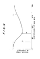
- the rotation speed of the crankshaft 64 is varied from fast to slow, because of a constant angle swing round the pin 69.
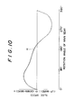
- the tilted angle (which shows a speed of the slide) of the motion Q11 is less than that of the motion Q io .
- the curve line of the motion Q becomes like a bottom shape of a wok (a deep round pan).
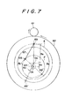
- a circle denoted by E, round an axis 0 8 is a drive rotation locus of center portion where the main gear 62 and the link 67 are connected one another by the pin member 69 when the main gear 62 rotates once
- a circle denoted by F, round an axis 0 9 is a driven rotation locus of center portion where the lever portion 64B of the crankshaft 64 and the link 67 are connected one another by the pin member 68.
- Figure 11 shows an swing angle of the link 67, when one rotation of the main gear 62 is transmitted to the crankshaft 64 as described in Figures 6 and 7.
- a length L caused by the swing angle can vary the rotation speed of the crankshaft 64 from fast to slow so as to trace the slide motion Q.
- maximum rotation speed of the crankshaft 64 is V 1 and minimum one is V 2 .
- High precise pressing by the slide motion Q needs the tilted angle e11 less than certain value.
- ratio Vi/V 2 should be high because V 1 means high rotation speed of the crankshaft 64 owing to swing of the link 67 and V 2 means low rotation speed.
- length difference between a radius R 3 of the drive rotation locus E and a radius R 4 of the driven rotational locus F is made large to keep the locus F inside of the locus E, so that the link 67 do not interfere with any other member while swinging.
- the link 67 is to have a certain length and be tilted toward the rotation direction so that the rotation of the main gear 62 is transmitted to that of the crankshaft 64. Accordingly, in order to increase Vi/V 2 until the certain value and obtain the length L by the angle ⁇ , the eccentric distance e 4 , shown in Figures 6 and 7, should be long.
- An object of the present invention is to provide a slide driving apparatus which attains a miniaturization of the apparatus by miniaturizing a diameter of the rotation center portion.
- An apparatus, in the present invention, for driving a slide by means of a crankshaft and a connecting rod in a press machine has: a rotational drive member capable of being rotated by a drive source and a corresponding driven member fixed to the crankshaft, in a state that both axes of the rotational drive member and the driven member are separated and opposing to one another; and a connecting member having two connecting centers, the first of which separates from the axis of the rotational drive member and is to be connected with the rotational drive member, the second of which separates from the axis of the driven rotation member and is to be connected with the driven rotation member, so that a drive rotation locus of the first connecting center round the axis of the rotational drive member and a driven rotation locus of the second connecting center round the axis of the driven rotation member intersect one another, an eccentric portion of the crankshaft being connected to the slide through the connecting rod.
- an apparatus, in the present invention, for driving a slide by means of a crankshaft and a connecting rod in a press machine has: a rotational drive member capable of being rotated by a drive source and a corresponding driven member fixed to the crankshaft, in a state that both axes of the rotational drive member and the driven member are separated and opposing to one another; a pin member of which one end portion is standing out from one surface of either the rotational drive member or the driven member along each axis; and a bush member capable of rotating in a state to be coupled into either the member which do not have the pin member, the pin member being coupled into the bush member at a distant point from an axis thereof and an eccentric portion of the crankshaft being connected with the slide through the connecting rod.
- the preferable rotational drive member is the main gear driven by the pinion, but it is also available to be a gear train or a disc-like member or a lever member which is driven by the drive shaft.
- the corresponding driven member is preferably to be the lever member, but a disc-like member or a lever member formed with the crankshaft is also available.
- Such arrangement can attain a wide rotation angle of the bush member while the rotational drive member and the driven member rotate once.
- a necessary length can be obtained so as to cause fluctuation of rotation speed for the crankshaft like in the conventional eccentric-link type system. Accordingly, the distance between axes of the rotational drive member and the driven member can be minimized, so that the diameter at the rotating portion where the eccentric portion of the apparatus is provided can be made small in size.
- Figure 1 is a front view showing the apparatus in the preferable embodiment according to the present invention.
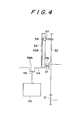
- Figure 2 is a schematic side view of the apparatus shown in Figure 1.
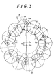
- Figure 3 is a schematic diagram for explanation of operation in Figures 1 and 2.
- Figure 4 is a schematic representation showing the conventional apparatus employing a slip element type system.
- Figure 5 is a schematic diagram for explanation of operation in Figure 4.
- Figure 6 is a schematic representation showing the conventional apparatus employing an eccentric-link type system.
- Figure 7 is a schematic diagram for explanation of operation in Figure 6.
- Figure 8 is a graphical representation of the slide motion which can return quickly.
- Figure 9 is a graphical representation of rotation speed of the crankshaft.
- Figure 10 is a graphical representation of speed of the slide.
- Figure 11 is an explanation view for swing angle of the link in order to obtain certain length.
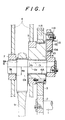
- FIG 1 is a front sectional view of an apparatus in the embodiment.
- Figure 2 is a schematic side view of the apparatus.
- a drive shaft 1 which is driven by a motor as a drive source has, on one end, a pinion 2 fitting into a main gear 3.
- the main gear 3 so relates to a large diameter bearing member 6, which is held by a boss member 5 of a frame 4, that the gear 3 can be rotated by the pinion 2 round an axis 0 1 .
- the main gear 3 is used in this embodiment as a rotational drive member.
- the bearing member 6 has a hole 6A for holding one potion of a crankshaft 8.
- the other portion of the crankshaft 8 is also held by a boss member 7 at its inner hole 7A.
- the crankshaft 8 has a round shaped eccentric portion 8A as shown in Figure 2.
- An axis of the eccentric portion 8A is denoted by 0 3 in the drawing and separated from the axis 0 2 by a distance of e 2 .
- the eccentric portion 8A is to be a portion to be connected with an upper portion of a connecting rod 9. While, a lower portion of the connecting rod 9 is connected to a not-shown slide, so that the slide will go up and down reciprocally two times longer than usual.
- one end portion of the crankshaft 8 is extended from the bearing member 6 and has a lever member 10 extending along a radial direction of the crankshaft 8.
- the lever 10, which is rotated so as to correspond with the rotation of the main gear 3, is employed as a driven member in this embodiment.
- the axis of the lever 10 is the same as the axis 0 2 of the crankshaft 8. Consequently, the lever 10 is eccentric from the main gear 3 by e i and opposes to the main gear 3 on the same axis.
- the main gear 3 has a hole in which a base portion 11A of a pin member 11 is inserted and held such that a potion of the pin member 11 stands out straight from one surface of the main gear 3.
- the lever member 10 has a hole 10A at nearly its forwarded end portion and distant from the axis 0 2 .
- the hole 10A is provided for holding a bush member 12 to rotate round the axis 0 4 as shown in Figure 2.
- a forwarded end portion 11 B of the pin member 11 is coupled into the bush member 12 and can rotate round an axis 0 5 separating from the axis 0 4 .
- a combination of the pin member 11 and the bush member 12 is to be called a connecting member 13 for connecting the main gear 3 with the lever member 10.
- the axis 0 5 is of a center for connecting the main gear 3 with one end portion of the connecting member 13 and the axis 0 4 is of a center for connecting the lever member 10 with the other end portion of the connecting member 13.
- the axis 0 5 traces over the drive rotation locus A described in Figures 2 and 3 round O 1 and the axis O 4 does the driven rotation locus B round 0 2 .
- the radius R 1 of the locus A is almost the same as the radius R 2 of the locus B, so that the locus A and B intersect one another at points C and D.
- the angle ⁇ 1 is more narrow than 180 degrees and the angle 0 2 is wider that 180 degrees. Accordingly, if the positional relationship between the pin member 11 and the eccentric portion 8A of the crankshaft 8 is defined as shown in Figure 2 and if the position of the slide shown in Figure 2 is defined to be its bottom dead center, the necessary time for the slide from its bottom dead center to top dead center is shorter that the opposite motion. In consequence, the upward motion of the slide become quick.
- a substantial length of the lever member 10 is shown by "R 2" which is a distance between two axes 0 2 and 0 4 .
- a mechanism employed in this embodiment seems to be comprised with the lever member 10 having a length R 2 and a link having a length I from the axis 0 4 to the axis 0 5 of which one end portion is connected with the main gear 3.
- such structure is likely to be the mentioned conventional apparatus having the lever portion 64B and the link 67, as shown in Figure 6.
- the apparatus employs the main gear 3 having the pin member 11 which is coupled into the bush member 12 rotating in the inside of the hole 10A of the lever member 10, so that the rotation of the main gear 3 makes the bush member 12 rotate, through the pin member 11, round the axis 0 4 and is transmitted to the lever member 10.
- This causes a wide rotation angle of the bush member 12 round the axis 0 4 when the main gear 3, the lever member 10 and the crankshaft 8 are rotated once all together.
- the slide motion Q drawn in Figure 8 for a high precise pressing of material, can be obtained by the length L drawn in Figure 11 which causes a deviation of the rotation speed of the crankshaft. While, in this invention, since the rotation angle of the bush member 12 round the axis 0 4 can be made widely, a swing angle a of the link 14, which has a length I equal to the distance between two axes 0 4 and 0 5 as can be seen from Figure 11, becomes wide. Therefore, according to the present invention, to obtain the length L of the link 14 having the distance I is easier than by the link 67 shown in Figures 6 and 11.
- the necessary length L can be kept, even though the distance ei, which is a distance between the axis 0 1 for the main gear 3 and the axis 0 2 for the lever member 10 and the crankshaft 8, is made short.
- the slide motion Q in Figure 8 can be achieved by the short distance e i , so that a rotatable center portion influenced by the distance e i , that is, such portions as the crankshaft 8, the bearing member 6, or the like, will become small in size. This is therefore desirable for the apparatus to minimize its size.
- the pin member 11 was provided at the side of the main gear 3 and the bush member 12 was done at the side of the lever member 10.
- this arrangement can be changed round.
- the connecting member 13 to join the rotational drive member with the driven member consists of the pin member 11 and the bush member 12 in the mentioned embodiment.
- the connecting member 13 may be a single link having a rod shape.
- the employed rotational drive member is the main gear 3 driven by the pinion 2 in this embodiment, but it is also available to be a gear train or a disc-like member or a lever member which is driven by the drive shaft 1.
- the corresponding driven member is also not limited to be the lever member 10, but a disc-like member or a lever member formed with the crankshaft 8.
- the rotational center portion where the eccentric portion in the apparatus is provided can be made small in size. Therefore, totally, the apparatus can be made small in size, some members employed in the apparatus can be processed easily and then the working efficiency and the necessary cost for production of the apparatus should be improved.
Landscapes
- Engineering & Computer Science (AREA)
- Mechanical Engineering (AREA)
- Press Drives And Press Lines (AREA)
- Transmission Devices (AREA)
Applications Claiming Priority (4)
| Application Number | Priority Date | Filing Date | Title |
|---|---|---|---|
| JP81959/91 | 1991-03-19 | ||
| JP81958/91 | 1991-03-19 | ||
| JP8195991A JPH04288994A (ja) | 1991-03-19 | 1991-03-19 | プレス機械のスライド駆動装置 |
| JP8195891A JPH0785839B2 (ja) | 1991-03-19 | 1991-03-19 | プレス機械のスライド駆動装置 |
Publications (2)
| Publication Number | Publication Date |
|---|---|
| EP0505026A2 true EP0505026A2 (de) | 1992-09-23 |
| EP0505026A3 EP0505026A3 (en) | 1993-03-03 |
Family
ID=26422940
Family Applications (1)
| Application Number | Title | Priority Date | Filing Date |
|---|---|---|---|
| EP19920301073 Ceased EP0505026A3 (en) | 1991-03-19 | 1992-02-07 | Slide driving apparatus of press machine |
Country Status (2)
| Country | Link |
|---|---|
| US (1) | US5226337A (de) |
| EP (1) | EP0505026A3 (de) |
Cited By (2)
| Publication number | Priority date | Publication date | Assignee | Title |
|---|---|---|---|---|
| EP0622873A3 (de) * | 1993-04-26 | 1996-03-27 | Whitaker Corp | Stössel Antriebsmechanismus. |
| US7152523B2 (en) | 2000-06-26 | 2006-12-26 | Aida Engineering Co., Ltd. | Press machine |
Families Citing this family (6)
| Publication number | Priority date | Publication date | Assignee | Title |
|---|---|---|---|---|
| US6164147A (en) * | 1999-02-05 | 2000-12-26 | The Minster Machine Company | Adjustable link motion press |
| US6311612B1 (en) | 1999-07-12 | 2001-11-06 | The Minster Machine Company | Link adjustment member |
| JP3701005B2 (ja) * | 2000-05-11 | 2005-09-28 | アイダエンジニアリング株式会社 | プレス機械のスライド駆動装置 |
| CN109332467A (zh) * | 2018-11-26 | 2019-02-15 | 明勖(东莞)精密机械有限公司 | 一种变曲线式高效拉伸冲床 |
| CN110466184B (zh) * | 2019-09-26 | 2024-03-22 | 明勖(东莞)精密机械有限公司 | 一种冲床送料机的传动机构 |
| JP7304842B2 (ja) | 2020-09-28 | 2023-07-07 | アイダエンジニアリング株式会社 | プレス機械 |
Family Cites Families (10)
| Publication number | Priority date | Publication date | Assignee | Title |
|---|---|---|---|---|
| US2255614A (en) * | 1940-04-17 | 1941-09-09 | Fox Meyer | Eccentric satellite crank |
| US2775128A (en) * | 1952-07-14 | 1956-12-25 | The Third National Ba Rockford | Device for changing circular motion to rectilinear motion |
| US3572137A (en) * | 1969-05-21 | 1971-03-23 | Aida Tekkosho Kk | Slide drive mechanism for a press |
| US3869927A (en) * | 1973-09-06 | 1975-03-11 | Gulf & Western Ind Prod Co | Geared drag link-slider-crank press |
| JPS5325388B2 (de) * | 1973-12-11 | 1978-07-26 | ||
| JPS60154897A (ja) * | 1984-01-23 | 1985-08-14 | Aida Eng Ltd | ダブルポイントプレス |
| JPS60154896A (ja) * | 1984-01-23 | 1985-08-14 | Aida Eng Ltd | ダブルポイントプレス機械 |
| US4697466A (en) * | 1985-04-24 | 1987-10-06 | Aida Engineering, Ltd. | Drive device for press |
| JPS62275599A (ja) * | 1986-05-06 | 1987-11-30 | Aida Eng Ltd | プレス機械のクランク軸結合方法 |
| JPS6440634A (en) * | 1987-07-31 | 1989-02-10 | Tetsutoshi Nakajima | Tape yarn woven fabric and tape yarn |
-
1992
- 1992-01-30 US US07/828,045 patent/US5226337A/en not_active Expired - Fee Related
- 1992-02-07 EP EP19920301073 patent/EP0505026A3/en not_active Ceased
Cited By (2)
| Publication number | Priority date | Publication date | Assignee | Title |
|---|---|---|---|---|
| EP0622873A3 (de) * | 1993-04-26 | 1996-03-27 | Whitaker Corp | Stössel Antriebsmechanismus. |
| US7152523B2 (en) | 2000-06-26 | 2006-12-26 | Aida Engineering Co., Ltd. | Press machine |
Also Published As
| Publication number | Publication date |
|---|---|
| US5226337A (en) | 1993-07-13 |
| EP0505026A3 (en) | 1993-03-03 |
Similar Documents
| Publication | Publication Date | Title |
|---|---|---|
| KR940001203B1 (ko) | 자동 조종용 기어 두부 | |
| EP0505026A2 (de) | Stösselantriebsvorrichtung für eine Presse | |
| US4671126A (en) | Walking beam pumping unit | |
| JPS6229070B2 (de) | ||
| US4103556A (en) | Mechanical movement mechanism | |
| JP2000271799A (ja) | プレス機 | |
| US5299516A (en) | Looper drive mechanism of a sewing machine | |
| US4022082A (en) | Driving apparatus for oscillation of a mold within a continuous casting machine | |
| US4329899A (en) | Device for converting rotary motion of crank mechanism into linear motion for a flying cutter | |
| US5546878A (en) | Looper drive mechanism for sewing machine | |
| JPH11245096A (ja) | スライダリンクプレス | |
| US3971261A (en) | Slide driving device for use in metal working press | |
| JP4291896B2 (ja) | プレス機 | |
| JPH0785839B2 (ja) | プレス機械のスライド駆動装置 | |
| FR2623463A1 (de) | ||
| JPH0359797B2 (de) | ||
| JPS62275599A (ja) | プレス機械のクランク軸結合方法 | |
| US4358977A (en) | Cutoff press | |
| JPH08118095A (ja) | プレス機械の下死点調整機構 | |
| KR920008552B1 (ko) | 소성가공방법 및 그 장치 | |
| CN1026508C (zh) | 一种三线包缝机 | |
| KR910001388Y1 (ko) | 피동 로울러 선회기구 | |
| JPH04288994A (ja) | プレス機械のスライド駆動装置 | |
| SU1368194A1 (ru) | Механический пресс | |
| SU1468682A2 (ru) | Фрезерна головка |
Legal Events
| Date | Code | Title | Description |
|---|---|---|---|
| PUAI | Public reference made under article 153(3) epc to a published international application that has entered the european phase |
Free format text: ORIGINAL CODE: 0009012 |
|
| AK | Designated contracting states |
Kind code of ref document: A2 Designated state(s): DE GB IT |
|
| PUAL | Search report despatched |
Free format text: ORIGINAL CODE: 0009013 |
|
| AK | Designated contracting states |
Kind code of ref document: A3 Designated state(s): DE GB IT |
|
| 17P | Request for examination filed |
Effective date: 19930813 |
|
| 17Q | First examination report despatched |
Effective date: 19940712 |
|
| 18R | Application refused |
Effective date: 19950528 |