EP0504311B1 - Process for the manufacture of thick-walled shaped articles for use, in particular, for packaging purposes - Google Patents
Process for the manufacture of thick-walled shaped articles for use, in particular, for packaging purposes Download PDFInfo
- Publication number
- EP0504311B1 EP0504311B1 EP91902425A EP91902425A EP0504311B1 EP 0504311 B1 EP0504311 B1 EP 0504311B1 EP 91902425 A EP91902425 A EP 91902425A EP 91902425 A EP91902425 A EP 91902425A EP 0504311 B1 EP0504311 B1 EP 0504311B1
- Authority
- EP
- European Patent Office
- Prior art keywords
- suction
- type
- suction surface
- holes
- moulding tool
- Prior art date
- Legal status (The legal status is an assumption and is not a legal conclusion. Google has not performed a legal analysis and makes no representation as to the accuracy of the status listed.)
- Expired - Lifetime
Links
Images


Classifications
-
- D—TEXTILES; PAPER
- D21—PAPER-MAKING; PRODUCTION OF CELLULOSE
- D21J—FIBREBOARD; MANUFACTURE OF ARTICLES FROM CELLULOSIC FIBROUS SUSPENSIONS OR FROM PAPIER-MACHE
- D21J7/00—Manufacture of hollow articles from fibre suspensions or papier-mâché by deposition of fibres in or on a wire-net mould
Definitions
- the invention relates to a method and a suction mold for the production of thick-walled shaped pieces, in particular for packaging purposes.
- the invention is therefore based on the object to improve the known method of suction molding and the suction molds necessary for this in such a way that, in particular from waste paper and / or cardboard waste in shredded form, substantially more stable molded articles should be able to be produced.
- the suction mold for carrying out the method, it consists of a suction box with a vacuum connection and with a suction surface corresponding to the desired shape of the packaging molding, the suction surface being made of a dimensionally stable support with holes distributed over the suction surface and spaced apart from one another, and that the support is suitable for molding with at least a fine-meshed layer, such as a mesh, grid or fabric layer is covered, the mesh size of which is kept smaller than the cross section of the holes.
- At least one further suction surface with a separate suction box is arranged on the suction side is associated with its area close to the other suction surface at a distance that corresponds to a maximum of twice the wall thickness of the packaging molding to be produced.
- the negative pressure is maintained for a certain period of time in order to at least roughly dewater the molding, which, however, due to its wall thickness and despite the residual water content that is still present, is already so stable that it can already be removed from the suction mold can while maintaining its specified shape.
- the larger wall thickness after drying of the shaped part also ensures that it has sufficient stability or rigidity to be able to serve as a replacement for the polystyrene shaped pieces.
- waste paper and / or cardboard waste can be used without further notice, which only requires comminution but does not require preparation for fiber digestion, that is to say the wastes comminuted into chips are merely added to the suspension liquid, softened and then the suspension enriched with chips can be used can be processed directly.
- plastic chips which are often found in paper and cardboard waste. It has been found that the presence of plastic chips in the finished shaped pieces is even advantageous, since these contribute to the increased strength of the shaped pieces, but more than 5% plastic chips should not be included.
- binders are still added to the suspension, then such binders are suitable as are customary in paper production, for example rosin saponified with boiling soda solution or sodium hydroxide solution, but also phenolic resins, coumarone resins, montan resins or resins from pulp liquor.
- resin glues casein, starch, animal glue, water glass or the like can also be used as additives for the sizing.
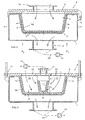
- the suction mold consists of a suction box 1 with a vacuum or vacuum connection 2 and a suction surface 3 adapted to the desired shape of the shaped piece VS. If the suction box 1 is provided with a cover 9, as shown in FIG. 4 is, this has a correspondingly large inflow connection 10 for the suspension, through which the suspension flows when the entire molding box 1 is exchanged for the suspension in the mold cavity.
- the suction surface 3 according to FIG.
- the suction surface 3 consists of a dimensionally stable support 4 with holes distributed over the suction surface and spaced apart from one another 5 (see also FIG. 3), the carrier 4 being covered on the side on which the shaped piece VS is to be formed with at least one fine-mesh layer 6 such as a mesh, grid or fabric layer (for example made of nylon), whose mesh size is kept substantially smaller than the cross section of the holes 5.
- the holes 5 have a diameter D of 1 to 2 mm, preferably 1.5 mm and a distance A from each other of 4 to 6 mm, preferably 5 mm.
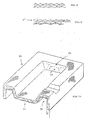
- wire mesh is preferably used for the layer, which has a wire thickness of 0.2 to 0.4 mm, the wires 7 in the fabric having a distance A 1 of 0.3 to 0.5 mm. It has proven to be particularly advantageous and effective that the crossing wires 7 of the fine-meshed layer 6 extend in two planes E, as illustrated in FIG. 2.
- the mesh size of the individual layers may well be the same or approximately the same as the size of the holes 5, since this results in a staggering of the passages in the depth.
- one or more layers 6 can also take over the function of the carrier 4, ie replace it, the layer 6 ′ on the suction side imparting its fine surface structure to the shaped piece. With such a design it is of course a prerequisite that the material for the layers 6 is a dimensionally stable material, ie it must not be a soft textile fabric, for example.
- the material to be used for the formation of the layer 6 can be both dimensionally stable and, preferably, dimensionally stable material, in the latter case there being the possibility, for example, of the layer 6 by pressing in corresponding tools of the shape of Adjust carrier 4 and to fix them on the carrier 4 in a suitable manner.
- the top view (in the direction of arrow P according to FIG. 2) in FIG. 3 corresponds to the dimensions of an actual embodiment in which the holes 5 have a hole size of approximately 1 mm in diameter, the layer 6 having a mesh size two to four times smaller, and further comprising flat F and strip-shaped waste SA, as shown, in the supplied slurry.
- Flat wastes, i.e. chips have sizes of about 1 to 6 cm2, with which the best results could be achieved.
- Stiff-shaped that is, sauerkraut-like waste SA, such as is obtained when comminuting, for example, file papers, has dimensions of about 1 to 5 mm in width and about 10 to 30 cm in length.
- suction surfaces 3 in the mold boxes 1 according to FIGS. 4, 5 are shown there in the simplest form.
- Other and much more complicated shapes of the carrier 4 and the associated layer 6 are, however, readily possible, care being taken only to ensure that there are no areas in which the suction-effective areas shield one another, which prevents precipitation or suction of raw material particles.
- the suction mold F is to make these at least two parts and thus the moldings F1 and F2 movable apart .
- a suitable hinge 14 is sufficient for being able to swing open the upper mold parts 9.
- the shaped piece formed is in a position, owing to its larger wall thickness, to withstand the loads which occur when the shape is divided, ie not to tear. With the greater wall thickness that can be achieved, there is also the advantage of being able to be shaped using divisible molds.
- the covers 9 result in clean edges on the shaped pieces.
- FIG. 5 is that at least one further suction surface 3 'with a separate suction box 1' is arranged on the suction side F, this suction box 1 'having a separate suction nozzle 1' '.
- the further suction surface 3 ' is associated with its area 8 close to the other suction surface 3 at a distance D 1 which corresponds at most to approximately twice the wall thickness S of the molded part VS to be produced.
- FIG. 6 shows a view of a molded part VS produced from the non-smooth side and FIG. 7 shows a section through such a molded part, wherein, as also from FIG. 7 It can be seen that two such shaped pieces serve to fix an article G to be packaged in a cardboard box K.
- the web cavities 13, as indicated in FIG. 6, result from the suction surfaces 3 ′ additionally arranged in the form F according to FIG. 5.
- the spacing of the holes 5 in the carrier 4 from one another is concerned, it is important to note in this regard that on the one hand a sufficiently large suction cross section is created on the one hand and on the other hand the carrier 4 is sufficiently stable to withstand high vacuum (e.g. 120 mb ) not to deform in relation to its specified shape.
- the distance values are fluid, since they depend on the hole size, the carrier material, the wall thickness of the carrier and ultimately also on the material of the fine-meshed layer 6 applied directly to the carrier 4. So far, too the hole spacing (for example, corresponding to the diameter of the holes 5) is also a factor to be considered for the wall thickness of the shaped pieces to be achieved.
- FIG. 11 shows the flow diagram of the entire process.
- the paper waste 16 is brought to the desired shredder size in a suitable shredding machine 17 and is conveyed into the mixing tank 18, to which a sufficient quantity of suspension liquid is fed from a tank 19.
- This liquid with the chips contained therein and softened then passes into the actual work basin 20, into which the molding boxes 1 are immersed with a suitable lifting mechanism 21, these molding boxes 1 being connected on the suction side to a vacuum pump 24 via a vacuum line 22 and a pressure-tightly closed separating container 23 are.
- the aspirated liquid is returned from the container 23 to the tank 19 by a pump 25 and from there takes part in the cycle again.
- all tanks and containers are provided twice and are accordingly integrated into the system. This double arrangement serves, in particular, to have sufficient time in the mixing containers 18 for the continuous input of the softening of the batch of chips entered in each case.
- the chips produced from the paper waste 16 with the shredding machine 17 have a shape that cannot be defined geometrically, but a cut size of the order of 1 to 6 cm 2.
- Approx. 500 liters of liquid with a quantity of chips of 3 to 5 kg are prepared and mixed in the mixing container.
- the liquid temperature corresponds to the normal ambient or line temperature, but can be increased if this is required by the peculiarity of the schnitzel.
- the residual moisture in the molding produced depends on how long the suction pressure on molding box 1 remains when it comes from the suspension in the Working pool 20 is lifted out by means of the lifting mechanism 21. After removal from the molding box 1, the molding or the molding is dried in a dryer 26.
- the molded part VS that can be produced with the method and the device according to the invention is shown in perspective in FIG. 10, the illustrated shape being to be understood only as an example. It is important here that stiffening web designs 11 are present in the channel 30 on the raw side of the shaped piece VS, which is only indicated by dashed lines at one point, which limit the web cavities 13. Seen from the raw side (in the direction of arrow 31), these web cavity spaces 13 have smooth walls and have a bottom 32 which has twice the wall thickness S of the fitting VS. As can be seen from FIG. 6, a plurality of such web cavities 13 can be provided on the rear or raw side of the shaped piece, i.e. a corresponding number of additional, separate suction boxes 1 'are then arranged in the suction mold according to the invention according to FIG. These additional suction boxes 1 'are attached to the cover 9, which has correspondingly large mass inflow openings 33.
Abstract
Description
Die Erfindung betrifft ein Verfahren und eine Saugform zur Herstellung von dickwandigen Formstücken, insbesondere für Verpackungszwecke.The invention relates to a method and a suction mold for the production of thick-walled shaped pieces, in particular for packaging purposes.
Verfahren und Saugformen für den genannten Zweck sind bekannt, bspw. nach Paper Trade Journal, 13.11.53, S. 175-180. Mit einem derartigen Verfahren und entsprechenden Saugformen können Formstücke hergestellt werden, die jedoch nur relativ dünnwandig und damit relativ weich, d.h. bis zu einem gewissen Grade instabil sind. Diese Formstücke bedürfen, um sie bei entsprechendeer Dünnwandigkeit überhaupt von der Saugform abnehmen zu können, einer unmittelbar der Saugausformung nachfolgenden Entwässerungs- und Trocknungsbehandlung. Derartige bekannte Formstücke genügen zwar bspw. in Form von "Eierkistchen" oder schalenartigen Obst- und Gemüseunterlagen trotz ihrer Dünnwandigkeit der an sie zu stellenden Anforderungen, sie sind aber nicht dafür geeignet sind, um Formstücke aus Polystyrol zu ersetzen, die notwendig sind, um schwerere Gegenstände, bspw. Geräte aller Art oder Geräteteile in einem Verpackungskarton festzulegen, obgleich dies in Rücksicht auf Umweltgesichtspunkte in hohem Maße wünschenswert wäre. Aus diesem Grunde werden nach wie vor Geräte, Geräteteile oder bspw. auch Wein- und Sektflaschengebinde in formangepaßten Polystyrolformstücken und in entsprechenden Kartonagenumhüllungen eingebracht, da nur mit solchen Formstücken eine unverschliebliche Lagerung in der Kartonage und zudem ein brusschsicherer Versand bzw. Transport gewährleistet sind. Dem Ersatz von Polystyrolformstücken durch Formstücke auf Basis von leicht- und umweltfreundlich verrottbarem Faserstoffmaterial stand bisher entgegen, daß mit einem derartigen Rohmaterial, wie gesagt, nur Formstücke mit geringer Wandstärke hergestellt werden konnten, die einerseits wegen mangelnder Eingenstabilität im Feuchtzustand nicht unmittelbar nach Ansaugformung von der Saugform entfernt werden können, was im Sinne einer rationalen Fertigung wünschenswert wäre und die andererseits aufgrund ihrer Dünnwandigkeit für schwereres Verpackungsgut nicht die notwendige Verschiebe- und Bruchsicherheit innerhalb einer Verpackungskartonage bieten können. Bezüglich solcher Formstücke wird auf die US-A-3 016 177 und 3 115 450 verwiesen, die jedoch nur aus entsprechend aufbereiteter Faser-Pulpe herstellbar und dünnwandig (maximal bis 3 mm) sind und die deshalb auch einer starken rippenartigen Strukturierung bedürfen, um sie überhaupt ausreichend steif zu machen. Einschlägige Saugformen sind nach der DE-A-26 44 487 und nach der EP-A-0 153 101 bekannt, mit denen zwar Formkörper mit etwas größerer Wandstärke als 3 mm hergestellbar zu sein scheinen, die aber trotzdem hinsichtlich ihrer Stabilität zu wünschen übrig lassen und nicht ohne weiteres als Ersatz für die vorerwähnten Polystyrol Verpackungsformstücke verwendet werden können.Methods and suction forms for the stated purpose are known, for example according to the Paper Trade Journal, November 13, 1953, pp. 175-180. Such a method and corresponding suction molds can be used to produce moldings which, however, are only relatively thin-walled and therefore relatively soft, ie are to a certain extent unstable. In order to be able to remove them from the suction mold at all with the appropriate thin walls, these fittings require a dewatering and drying treatment immediately following the suction molding. Such known fittings are sufficient, for example in the form of "egg crates" or bowl-like fruit and vegetable underlays despite their thin walls, but they are not suitable for replacing polystyrene fittings which are necessary for heavier ones To fix objects, for example devices of all kinds or device parts in a packaging box, although this would be highly desirable from an environmental point of view. For this reason, devices, device parts or, for example, wine and champagne bottles are still placed in shape-matched polystyrene moldings and in appropriate cardboard packaging, since only with such moldings can packaging and packaging be protected against breakage and also ensure safe shipping and transport. The replacement of polystyrene fittings by fittings based on easily and environmentally friendly decomposable fibrous material was previously opposed to the fact that with such a raw material, as mentioned, only fittings with small wall thicknesses could be produced which, on the one hand, could not be used immediately after suction molding due to a lack of individual stability in the wet state Suction form can be removed, which would be desirable in the sense of a rational production and the other because of their Thin walls for heavier packaged goods cannot offer the necessary resistance to movement and breakage within a packaging box. With regard to such fittings, reference is made to US Pat. Nos. 3,016,177 and 3,115,450, which, however, can only be produced from appropriately prepared fiber pulp and are thin-walled (up to 3 mm maximum) and which therefore also require a strong rib-like structuring in order to be able to use them to make it sufficiently stiff at all. Relevant suction forms are known from DE-A-26 44 487 and from EP-A-0 153 101, with which molded articles with a wall thickness somewhat larger than 3 mm seem to be producible, but which still leave something to be desired in terms of their stability and cannot readily be used as a replacement for the aforementioned polystyrene packaging moldings.
Der Erfindung liegt demgemäß die Aufgabe zugrunde, das bekannte Verfahren der Saugausformung und die dafür notwendigen Saugformen dahingehend zu verbessern, daß ausgehend insbesondere von Altpapier- und/oder kartonagenabfällen in Schnitzelform damit wesentlich stabilere Formkörper herstellbar sein sollen.The invention is therefore based on the object to improve the known method of suction molding and the suction molds necessary for this in such a way that, in particular from waste paper and / or cardboard waste in shredded form, substantially more stable molded articles should be able to be produced.
Diese Aufgabe ist mit einem Verfahren der eingangs genannten Art nach der Erfindung dadurch gelöst,
daß zum und im Saugformwerkzeug mindestens ein weiteres, kleineres Saugformwerkzeug in Distanz gehalten und dieses kleinere Saugformwerkzeug gleichzeitig mit dem anderen größeren Saugwerkzeug unter Saugdruck gesetzt und dabei die beiden entstehenden Formstücke zu einem zusammenhängenden Formstück ausgebildet werden.This object is achieved with a method of the type mentioned according to the invention in that
that at least one other, smaller suction molding tool is kept at a distance from and in the suction molding tool and this smaller suction molding tool is simultaneously placed under suction pressure with the other larger suction tool, and the two resulting molded pieces are formed into a coherent molded piece.
Bezüglich der Saugform zur Durchführung des Verfahrens besteht diese aus einen Saugkasten mit Vakuumanschluß und mit einer der gewünschten Form des Verpackungsformstücks entsprechenden Saugfläche, wobei die Saugfläche aus einem formstabilen Träger mit über die Saugfläche verteilten und zueinander beabstandeten Löchern versehen ist und daß der Träger formstückanlageseltig mit mindestens einer feinmaschigen Lage, wie Netz-, Gitter- oder Gewebelage überdeckt ist, deren Maschenweite kleiner gehalten ist als der Querschnitt der Löcher Davon ausgehend und nach der Erfindung ist vorgesehen, daß in der Saugform ansaugseitig mindestens eine weitere Saugfläche mit separatem Saugkasten angeordnet ist, die mit ihrem der anderen Saugfläche nahen Bereich in einer Distanz, zugeordnet ist, die maximal einer doppelten Wandstärke des herzustellenden Verpackungsformstückes entspricht.With regard to the suction mold for carrying out the method, it consists of a suction box with a vacuum connection and with a suction surface corresponding to the desired shape of the packaging molding, the suction surface being made of a dimensionally stable support with holes distributed over the suction surface and spaced apart from one another, and that the support is suitable for molding with at least a fine-meshed layer, such as a mesh, grid or fabric layer is covered, the mesh size of which is kept smaller than the cross section of the holes. Based on this, and according to the invention it is provided that at least one further suction surface with a separate suction box is arranged on the suction side is associated with its area close to the other suction surface at a distance that corresponds to a maximum of twice the wall thickness of the packaging molding to be produced.
Überraschenderweise hat sich bei dieser erfindungsgemäßen Verfahrensweise in Verbindung mit der dafür speziell ausgebildeten Saugformgestaltung gezeigt, daß sich damit im Verbindungsbereich Wandstärken für derartige Formstücke erreichen lassen, die dem Doppelten der bisher erreichbaren Wandstärke entsprechen, womit sich derartig hergestellte Formstücke nicht nur sofort vom Saugformwerkzeug abnehmen bzw. entfernen lassen, sondern diese weisen dann auch im trockenen Zustand die notwendige Eigenstabilität auf, um als Ersatz für die für diesen Zweck bisher verwendeten Polystyrolformstücke dienen zu können.Surprisingly, it has been shown in this procedure according to the invention in connection with the specially designed suction mold design that wall thicknesses for fittings of this type can be achieved in the connection area which correspond to twice the wall thickness previously achievable, with which moldings produced in this way are not only immediately removed or removed from the suction mold can be removed, but these then have the necessary inherent stability even in the dry state, in order to be able to serve as a replacement for the polystyrene moldings previously used for this purpose.
Bei Beendigung des Saugvorganges wird der Unterdruck noch über eine gewisse Zeitspanne aufrecht erhalten, um das Formstück zumindest grob zu entwässern, das allerdings aufgrund seiner Wandstärke und trotz des noch vorhandenen Restwassergehaltes dann bereits in sich so stabil ist, daß es schon von der Saugform abgenommen werden kann und dabei auch seine vorgegebene Form beibehält. Außerdem sorgt aber dann auch die größere Wandstärke nach Trocknung des Formstückes dafür, daß dieses eine ausreichende Stbailität bzw. Steifheit besitzt, um als Ersatz für die Polystyrolformstücke dienen zu können.At the end of the suction process, the negative pressure is maintained for a certain period of time in order to at least roughly dewater the molding, which, however, due to its wall thickness and despite the residual water content that is still present, is already so stable that it can already be removed from the suction mold can while maintaining its specified shape. In addition, however, the larger wall thickness after drying of the shaped part also ensures that it has sufficient stability or rigidity to be able to serve as a replacement for the polystyrene shaped pieces.
Beim erfindungsgemäße Verfahren können ohne weiteres Altpapier- und/oder Kartonagenabfälle verwendet werden, die nur einer Zerkleinerung aber keiner Aufbereitung zu einem Faseraufschluß bedürfen, d.h., die zu Schnitzeln zerkleinerten Abfälle werden lediglich in die Aufschwemmflüssigkeit gegeben, angeweicht und dann kann die mit Schnitzeln angereicherte Aufschwemmung direkt verarbeitet werden.In the method according to the invention, waste paper and / or cardboard waste can be used without further notice, which only requires comminution but does not require preparation for fiber digestion, that is to say the wastes comminuted into chips are merely added to the suspension liquid, softened and then the suspension enriched with chips can be used can be processed directly.
Dabei spielt es keine Rolle, wenn in den Abfällen sehr vereinzelte Kunststoffolienschnitzel mit enthalten sind, die sich ja häufig mit in Papier- und kartonagenabfällen befinden. Wie sich herausgestellt hat, ist das Vorhandensein von Kunststoffschnitzeln in den fertiggestellten Formstücken sogar vorteilhaft, da diese zur erhölten Festigkeit der Formstücke beitragen, mehr als 5% Kunststoffschnitzel sollten aber nicht enthalten sein.It does not matter if the waste contains very isolated plastic film chips, which are often found in paper and cardboard waste. It has been found that the presence of plastic chips in the finished shaped pieces is even advantageous, since these contribute to the increased strength of the shaped pieces, but more than 5% plastic chips should not be included.
Wie sich gezeigt hat, ist es auch nicht zwingend erfolderlich, einer Schnitzelaufschwemmung im Wasser zusätzliche Bindemittel zuzusetzen, da sich in jedem Falle beim Ansaugvorgang ausreichende Schnitzelvernetzungen ergeben, die dann im Fertigzustand des jeweiligen Formstückes diesem eine ausreichend stabile Innenstruktur vermitteln. Außerdem bringt das zu verarbeitende Rohmaterial sowieso noch einen gewissen Anteil an Bindemittel mit, das in der Aufschwemmung in Lösung gegangen ist. Sofern dennoch Bindemittel der Aufschwemmung zugesetzt werden, so kommen für solche Bindemittel solche in Frage, wie sie bei der Papierherstellung üblich sind, also bspw. mit kochender Sodalösung bzw. Natronlauge verseiftes Kolophonium, aber auch Phenolharze, Cumaron-, Montanharze oder Harze aus Zellstoffablaugen. Es können dafür außer Harzleimen als Zusatzstoffe zur Leimung auch Casein, Stärke, Tierleim, Wasserglas od. dgl. zur Anwendung kommen.As has been shown, it is also not absolutely necessary to add additional binders to a suspension of chips in the water, since in any case sufficient chip cross-links result during the suction process, which then impart a sufficiently stable internal structure to the respective molded part when it is finished. In addition, the raw material to be processed also brings with it a certain proportion of binder that has dissolved in the suspension. If binders are still added to the suspension, then such binders are suitable as are customary in paper production, for example rosin saponified with boiling soda solution or sodium hydroxide solution, but also phenolic resins, coumarone resins, montan resins or resins from pulp liquor. In addition to resin glues, casein, starch, animal glue, water glass or the like can also be used as additives for the sizing.
Das erfindungsgemäße Verfahren, die zugehörige Saugform und weitere vorteilhafte und praktische Ausführungsformen werden nachfolgend anhand der zeichnerischen Darstellung von Ausführungsbeispielen näher erläutert.The method according to the invention, the associated suction form and further advantageous and practical embodiments are explained in more detail below with the aid of exemplary embodiments.
Es zeigt schematisch
- Fig. 1
- stark vergrößert einen Abschnitt der Saugfläche mit einem entsprechenden Abschnitt das darauf angesaugten Rohmaterials für die Ausbildung des Formstückes;
- Fig. 2
- noch stärker vergrößert einen Schnitt durch die erfindungsgemäß ausgebildete Saugfläche;
- Fig. 3
- eine Draufsicht auf die Saugfläche von der Rohmaterialauflageseite aus gesehen;
- Fig. 4
- einen Schnitt durch einen Saugkasten Art;
- Fig. 5
- einen Schnitt durch einen Saugkasten in besonderer Ausführungsform;
- Fig. 6
- die Ansicht eines Formstückes von der "Rohseite" her gesehen;
- Fig. 7
- einen Schnitt durch das Formstück gemäß Fig. 6 in Verbindung mit einem zu verpackenden Gegenstand;
- Fig. 8, 9
- im Schnitt besondere Ausführungsformen der Saugfläche;
- Fig. 10
- perspektivisch und geschnitten das Beispiel eines Formstückes und
- Fig. 11
- ein Fließschema des Verfahrens.
- Fig. 1
- greatly enlarges a section of the suction surface with a corresponding section of the raw material sucked thereon for the formation of the molding;
- Fig. 2
- an enlarged section through the suction surface designed according to the invention;
- Fig. 3
- a plan view of the suction surface seen from the raw material support side;
- Fig. 4
- a section through a suction box type;
- Fig. 5
- a section through a suction box in a special embodiment;
- Fig. 6
- the view of a fitting seen from the "raw side";
- Fig. 7
- a section through the molding of Figure 6 in connection with an object to be packaged.
- 8, 9
- on average special embodiments of the suction surface;
- Fig. 10
- perspective and cut the example of a fitting and
- Fig. 11
- a flow chart of the process.
Zunächst wird der grundsätzliche Aufbau einer Saugform beschrieben.
Wie aus Fig. 4 ersichtlich, besteht die Saugforms aus einem Saugkasten 1 mit Vakuum- bzw. Unterdruckanschluß 2 und einer der gewünschten Form des Formstückes VS anqepaßten Saugfläche 3. Sofern, wie in Fig. 4 dargestellt, der Saugkasten 1 mit einer Abdeckelung 9 versehen ist, weist diese einen entsprechend weit bemessenen Einströmanschluß 10 für die Aufschwemmung auf, durch den die Aufschwemmung beim Eintauschen des ganzen Formkastens 1 in die Aufschwemmung in den Formhohlraum einströmt. Um mit einer solchen Saugform Formstücke VS mit einer Wandstärke S von mindestens 4 bis 6 mm herstellen zu können, ist die Saugfläche 3 gemäß Fig. 1 derart ausgebildet, daß die Saugfläche 3 aus einem formstabilen Träger 4 mit über die Saugfläche verteilten und zueinander beabstandeten Löchern 5 besteht (siehe auch Fig. 3), wobei der Träger 4 auf der Seite, auf der das Formstück VS gebildet werden soll, mit mindestens einer feinmaschigen Lage 6 wie Netz-, Gitter- oder Gewebelage (bspw. aus Nylon) überdeckt ist, deren Maschenweite wesentlich kleiner gehalten ist als der Querschnitt der Löcher 5. Die Löcher 5 haben dabei einen Durchmesser D von 1 bis 2 mm, vorzugsweise 1,5 mm und einen Abstand A zueinander von 4 bis 6 mm, vorzugsweise 5 mm. Bevorzugt wird für die Lage 6 Kupferdrahtgewebe verwendet, das eine Drahtstärke von 0,2 bis 0,4 mm hat, wobei die Drähte 7 im Gewebe zueinander einen Abstand A₁ von 0,3 bis 0,5 mm haben. Als besonders vorteilhaft und wirksam hat sich erwiesen, daß die sich kreuzenden Drähte 7 der feinmaschigen Lage 6 in zwei Ebenen E, wie in Fig. 2 verdeutlicht, erstreckt sind. Durch die vergrößerte Darstellung gemäß Fig. 2 ist verdeutlicht und wie mit Pfeilen angedeutet, daß sich gewissermaßen Querströme in der Lage 6 ergeben, die offenbar mit dafür maßgebend sind, daß sich das in der Aufschwemmung befindliche Rohmaterial in gewünscht großer Schichtdicke auf der Lage 6 absetzen kann, was nicht möglich ist, wenn nur eine siebartige, relativ dünne und nur einen begrenzten Unterdruck zulassende Saugfläche benuzt wurde, die sich entsprechend schnell zusetzte und damit der Schichtdicke eine zu frühe Grenze setzte. Es können natürlich auch mehrere, sehr dünne Lagen 6 übereinander angeordnet werden, die im einzelnen eine Stärke von maximal nur ca. 1 mm haben. Bei dieser Lage 6 darf es sich also nicht um ein entsprechend dünnes und lediglich gelochtes Blech handeln, da sich an einem solchen Blech keine Querströmung ergeben kann. Bei einer mehrschichtigen Ausbildung der Lage 6 (siehe Fig. 8) kann die Maschenweite der einzelnen Lagen durchaus der Größe der Löcher 5 gleich oder angenähert gleich sein, da sich dabei gewissermaßen eine Staffelung der Durchlässe in der Tiefe ergibt. Je nach Materialauswahl für die Lagen 6 können bspw. auch eine oder mehrere Lagen 6 die Funktion des Trägers 4 übernehmen, d.h. diesen ersetzen, wobei die ansaugseitige Lage 6' dem Formstück seine feine Oberflächenstruktur vermittelt. Bei einer solchen Ausbildung ist natürlich Voraussetzung, daß es sich beim Material für die lagen 6 um formstabiles Material handelt, d.h. es darf bspw. kein weiches Textilgewebe sein.First, the basic structure of a suction mold is described.
As can be seen from FIG. 4, the suction mold consists of a
Beim für die Ausbildung der Lage 6 zu verwendenden Material kann es sich sowohl um nicht formstabiles als auch, dies bevorzugt, um formstabiles Material handeln, wobei im letzteren Fall die Möglichkeit besteht, die Lage 6 bspw. durch einen Preßvorgang in entsprechenden Werkzeugen der Form des Trägers 4 anzupassen und diese am Träger 4 in geeigneter Weise zu fixieren. Die Draufsichtsdarstellung (in Pfeilrichtung P gemäß Fig. 2) in Fig. 3 entspricht bezüglich der Abmessungen einer tatsächlichen Ausführungsform, bei der die Löcher 5 eine Lochgröße mit etwa 1 mm Durchmesser haben, wobei die Lage 6 eine zwei- bis vierfach kleinere Maschenweite aufweist, und wobei ferner flächige F und streifenförmige Abfälle SA, wie dargestellt, in der zugeführten Aufschwemmung enthalten sind. Flächige Abfälle, also Schnitzel, haben dabei Größen von etwa 1 bis 6 cm², mit denen die besten Ergebnisse erzielt werden konnten. Steifenförmige, also sauerkrautähnliche Abfälle SA, wie sie beim Zerkleinern von bspw. Aktenpapieren anfallen, haben dabei Abmessungen von etwa 1 bis 5 mm Breite und ca. 10 bis 30 cm Länge.The material to be used for the formation of the
Die Saugflächen 3 in den Formkästen 1 gemäß der Fig. 4, 5 sind dort in einfachster Form dargestellt. Andere und wesentlich kompliziertere Formgebungen des Trägers 4 und der zugehörigen Lage 6 sind jedoch ohne weiteres möglich, wobei nur darauf zu achten ist, daß sich keine Bereiche ergeben, in denen die saugwirksamen Bereiche sich gegenseitig abschirmen, was zu einer Verhinderung des Niederschlages bzw. Ansaugens von Rohmaterialteilchen führen würde.The suction surfaces 3 in the
Insbesondere in Rücksicht auf kompliziertere Formgebungen der Formstücke und der damit verbundenen, erschwerten Ausformbarkeit des hergestellten Formstückes, aber auch bei einfachen Formgebungen, wie dargestellt, besteht eine vorteilhafte Ausbildung der Saugform F darin, diese mindestens zweiteilig und damit die Formteile F₁ und F₂ auseinander bewegbar auszubilden. Bei einem einfachen Formkasten 1, wie in Fig. 4 dargestellt, genügt dafür ein geeignetes Gelenk 14, um die Formoberteile 9 aufschwenken zu können. Es ist aber auch möglich, und zwar insbesondere für komplizierte Formkästen gemäß Fig. 5, Hubfürungen 15 vorzusehen, mit deren Hilfe das Oberteil angehoben werden kann. Wie sich gezeigt hat, ist dabei das ausgebildete Formstück aufgrund seiner größeren Wandstärke durchaus in der Lage, den bei Teilung der Form auftretenden Belastungen zu widerstehen, d.h., nicht zu zerreißen. Mit der erreichbaren größeren Wandstärke ist also auch der Vorteil einer Ausformbarkeit mit Hilfe teilbarer Formen gegeben. Bei den in Fig. 4, 5 dargestellten Formen ergeben sich durch die Abdeckungen 9 saubere Ränder an den Formstücken.Particularly in view of more complicated shapes of the fittings and the associated, difficult formability of the molded part, but also with simple shapes, as shown, there is an advantageous embodiment of the suction mold F is to make these at least two parts and thus the moldings F₁ and F₂ movable apart . In the case of a
Die erfindungsgemäße Ausbildung der Saugform F gemäß Fig. 5 besteht darin, daß in der Saugform F ansaugseitig mindestens eine weitere Saugfläche 3' mit separatem Saugkasten 1' angeordnet ist, wobei dieser Saugkasten 1' über einen separaten Saugstutzen 1'' verfügt. Die weitere Saugfläche 3' ist dabei mit ihrem der anderen Saugfläche 3 nahen Bereich 8 in einer Distanz D₁ zugeordnet, die maximal etwa einer doppelten Wandstärke S des herzustellenden Formstückes VS entspricht. Damit ist es möglich und wie ohne weiteres erkannbar, das Formstück VS mit verseifenden Stegausbildungen 11 zu versehen, die zur weiteren Stabilität des Formstückes VS wesentlich beitragen, insbesondere was die mehr oder weniger großen Randbereiche 12 des Formstückes betrifft. Hierzu wird bspw. auf die Fig. 6, 7 verwiesen, wobei Fig. 6 eine Ansicht eines hergestellten Formstückes VS von der nicht glatten Seite her darstellt und die Fig. 7 einen Schnitt durch ein solches Formstück, wobei, wie ebenfalls aus Fig. 7 ersichtlich, zwei solcher Formstücke zur Fixierung eines zu verpackenden Gegenstandes G in einer Kartonage K dienen. Die Steghohlräume 13, wie in Fig. 6 angedeutet, ergeben sich dabei durch die zusätzlich in der Form F entsprechend angeordneten Saugflächen 3' gemäß Fig. 5.5 is that at least one further suction surface 3 'with a separate suction box 1' is arranged on the suction side F, this suction box 1 'having a separate suction nozzle 1' '. The further suction surface 3 'is associated with its
Was den Abstand der Löcher 5 im Träger 4 zueinander betrifft, so ist diesbezüglich als wesentlich zu beachten, daß einerseits insgesamt ein ausreichend großer Saugquerschnitt entsteht und andererseits der Träger 4 eine ausreichend hohe Stabilität erhält, um sich bei angelegten hohen Unterdrücken (bspw. 120 mb) nicht bezgl. seiner vorgegebenen Form zu deformieren. Auch hierbei sind also die Abstandswerte fließend, da diese von der Lochgröße, dem Trägermaterial, der Wandstärke des Trägers und letztlich auch vom Material der unmittelbar auf den Träger 4 aufgebrachten feinmaschigen Lage 6 abhängen. Insoweit sind also auch die Lochabstände (bspw. dem Durchmesser der Löcher 5 entsprechend) ebenfalls eine zu beachtende Einflußgröße für die zu erzielende Wandstärke der Formstücke.As far as the spacing of the
In Fig. 11 ist das Fließschema des gesamten Verfahrens dargestellt. Die Papierabfälle 16 werden in einer geeigneten Zerkleinerungsmaschine 17 auf die gewünschte Schnitzelgröße gebracht und in den Mischtank 18 befördert, dem aus einem Tank 19 eine ausreichende Menge Aufschwemmflüssigkeit zugeleitet wird. Diese Flüssigkeit mit den darin enthaltenen und aufgeweichten Schnitzeln gelangt dann in das eigentliche Arbeitsbecken 20, in das die Formkästen 1 mit einer geeigneten Hubmechanik 21 eingetaucht werden, wobei diese Formkästen 1 über eine Vakuumleitung 22 und einen druckdicht geschlossenen Abscheidebehälter 23 mit einer Vakuumpumpe 24 saugseitig verbunden sind. Die abgesaugte Flüssigkeit wird aus dem Behälter 23 mit einer Pumpe 25 in den Tank 19 zurückgefördert und nimmt von da aus wieder am Kreislauf teil. Wie gestrichelt angedeutet, sind alle Tanks und Behälter doppelt vorgesehen und entsprechend sinngemäß in die Anlage eingebunden. Diese Doppelanordnung dient insbesondere dazu, in den Mischbehältern 18 bei fortlaufender Produktion ausreichend Zeit für das Anweichen der jeweils eingegebenen Schnitzelcharge zu haben.11 shows the flow diagram of the entire process. The
Hierzu wird ebenfalls auf Fig. 11 Bezug genommen. Die aus den Papierabfällen 16 mit der Zerkleinerungsmaschine 17 hergestellten Schnitzel haben eine geometrisch nicht definierbare Form, aber eine Zuschnittsgröße in der Größenordnung von 1 bis 6 cm². Im Mischbehälter werden ca. 500 Ltr. Flüssigkeit mit einer Schnitzelmenge von 3 bis 5 kg angesetzt und vermischt. Die Flüssigkeitstemperatur entspricht der normalen Umgebungs- bzw. Leitungstemperatur, kann aber erhöht werden, wenn dies die Eigenart der Schnitzel verlangen sollte. Bei einem Fertiggewicht des herzustellenden Formstückes im trockenen Zustand von ca. 200 g, was einer Formkastengröße von etwa 400x400x150 mm³ entspricht, dauert der Saugvorgang bei einem angelegten Saugdruck von ca. 120 mb am Formkasten 1 und bei einer Wandstärke des herzustellenden Formstückes von 5 bis 6 mm nur ca. 3 bis 5 sec. Die Restfeuchte im hergestellten Formstück ist davon abhängig, wie lange der Saugdruck am Formkasten 1 angelegt bleibt, wenn dieser aus der Aufschwemmung im Arbeitsbecken 20 mittels der Hubmechanik 21 herausgehoben ist. Nach der Entnahme aus dem Formkasten 1 wird das Formstück bzw. werden die Formstücke in einem Trockner 26 getrocknet.For this purpose, reference is also made to FIG. 11. The chips produced from the
Das mit dem erfindungsgemäßen Verfahren und der Vorrichtung herstellbare Formstück VS ist in Fig.10 perspektivisch dargestellt, wobei die dargestellte Form nur als Beispiel zu verstehen ist. Wesentlich ist dabei, daß in der Rinne 30 auf der Rohseite des Formstückes VS, was nur gestrichelt an einer Stelle angedeutet ist, versteifende Stegausbildungen 11 vorhanden sind, die die Steghohlräume 13 begrenzen. Von der Rohseite aus gesehen( in Richtung des Pfeiles 31), weisen diese Stegholräume 13 glatte Wände auf und haben einen Boden 32, der die doppelte Wandstärke S des Formstückes VS aufweist. Wie aus Fig. 6 ersichtlich, können auf der Rück- bzw. Rohseite des Formstückes mehrere solche Steghohlräume 13 vorgesehen werden, d.h., in der erfindungsgemäßen Saugform gemäß Fig.5 ist dann eine entsprechende Anzahl zusätzlicher, separater Saugkästen 1' angeordnet. Diese zusätzlichen Saugkästen 1' sind am Deckel 9 befestigt, der entsprechend große Masseeinströmöffnungen 33 aufweist.The molded part VS that can be produced with the method and the device according to the invention is shown in perspective in FIG. 10, the illustrated shape being to be understood only as an example. It is important here that stiffening web designs 11 are present in the
Claims (7)
- A process for the manufacture of thick-walled preforms, in particular, for packing purposes, especially from waste paper and/or cardboard waste, with the raw material contained in a water wash being sucked from the wash by means of a suction-type pulp moulding tool onto the suction surface conforming to the shape of the packing preform, wherein the suction on the moulding tool is exerted on the washed and sucked-in raw material within the wash, through spaced-apart holes in the suction surface and through a suction-permeable coating composed of one or more layers,with the coating being disposed immediately ahead of the suction surface and being of a mesh size dimensioned smaller than the hole size,
characterized in
that at least one additional smaller-sized suction-type pulp moulding tool is kept in spaced relationship from the suction-type moulding tool, and that the said smaller-sized suction-type moulding tool along with the other larger-sized suction-type moulding tool is placed under suction pressure, with the two resultant preforms being formed to constitute one coherent preform. - A suction-type pulp mould for carrying out the process according to claim 1, comprising a plenum chamber (1) having a vacuum connection (2) and a suction surface (3) conforming to the desired shape of the packing preform (VS), with the suction surface (3) of a form-stable carrier (4) being provided with spaced-apart holes (5) distributed throughout the suction surface, and with the carrier (4), at the abutment side of the preform being covered by at least one fine-mesh coating (6), such as a grid, lattice or fabric coating the mesh size of which is dimensioned smaller than the cross-section of the holes (5), characterized in that disposed in the divisible suction-type mould (F), at the intake side thereof, is at least one other suction surface (3') having a separate plenum chamber (1'), which suction surface (3') with the area thereof (8) close to the other suction surface (3), is disposed at a space (D₁) which, at best, corresponds to the double wall thickness (S) of the packing preform (VS) to be manufactured.
- A suction-type mould according to claim 2, characterized in that the suction-type mould (F) is provided with a cover (9) on which is arranged the at least one additional plenum chamber (1') and which is provided with a material in-flow opening (32).
- A suction-type mould according to claims 2 or 3, characterized in that the crossing cords (7) of the at least one fine-mesh coating (6) extend within two planes (E).
- A suction-type mould according to claims 2 or 3, characterized in that the at least one coating (6) is of a form-stable configuration and is preformed to conform to the shape of the carrier (4).
- A suction-type mould according to claims 2 or 3, characterized in that the holes (5) of the carrier (4) are of a diameter (D) of 0.5 to 3 mm, preferably 1 to 2 mm, and that the space (A) of two holes (5) from one another is between 2 and 8 mm, preferably 5 mm.
- A suction-type mould according to claims 2 or 3, characterized in that the suction-type mould (F) is at least of a bipartite configuration, and the preforms (F₁, F₂) are designed to be movable apart.
Applications Claiming Priority (2)
| Application Number | Priority Date | Filing Date | Title |
|---|---|---|---|
| DE4001918 | 1990-01-24 | ||
| DE4001918A DE4001918C1 (en) | 1990-01-24 | 1990-01-24 |
Publications (2)
| Publication Number | Publication Date |
|---|---|
| EP0504311A1 EP0504311A1 (en) | 1992-09-23 |
| EP0504311B1 true EP0504311B1 (en) | 1993-07-28 |
Family
ID=6398618
Family Applications (1)
| Application Number | Title | Priority Date | Filing Date |
|---|---|---|---|
| EP91902425A Expired - Lifetime EP0504311B1 (en) | 1990-01-24 | 1991-01-23 | Process for the manufacture of thick-walled shaped articles for use, in particular, for packaging purposes |
Country Status (7)
| Country | Link |
|---|---|
| EP (1) | EP0504311B1 (en) |
| AT (1) | ATE92125T1 (en) |
| CA (1) | CA2069295A1 (en) |
| DE (2) | DE4001918C1 (en) |
| DK (1) | DK0504311T3 (en) |
| ES (1) | ES2044722T3 (en) |
| WO (1) | WO1991011555A1 (en) |
Families Citing this family (4)
| Publication number | Priority date | Publication date | Assignee | Title |
|---|---|---|---|---|
| DE4106986A1 (en) * | 1991-03-05 | 1992-09-10 | Charles Ulbricht | PACKING SYSTEM DAEMM, INSULATION AND CARRIER PLATE |
| DE4332680A1 (en) * | 1993-09-25 | 1995-03-30 | Karl Schenk Inh Roland Schenk | Moulds for pouring and/or handling mouldings |
| JPH09203423A (en) * | 1996-01-25 | 1997-08-05 | Toyota Motor Corp | Manufacture of rustproof cover and rustproof cover using this manufacture |
| WO2003018911A1 (en) * | 2001-08-16 | 2003-03-06 | Arnulfo Lopez Hernandez | Decorative figures and pinatas which are made from recycled card and paper and which are produced in a high-vacuum chamber |
Family Cites Families (5)
| Publication number | Priority date | Publication date | Assignee | Title |
|---|---|---|---|---|
| US3261740A (en) * | 1963-09-27 | 1966-07-19 | Diamond Int Corp | Method and mold for producing multilayer absorbent tray |
| US3325349A (en) * | 1964-03-18 | 1967-06-13 | Diamond Int Corp | Method and mold for controlling stock thickness in a pulp molding operation |
| US4014739A (en) * | 1974-05-09 | 1977-03-29 | International Paper Company | Mold construction having removable base member |
| US4034447A (en) * | 1975-10-02 | 1977-07-12 | Idra Ag | Papier-mache coffin |
| GB8403507D0 (en) * | 1984-02-10 | 1984-03-14 | Vernon & Co Pulp Prod | Moulding |
-
1990
- 1990-01-24 DE DE4001918A patent/DE4001918C1/de not_active Expired - Fee Related
-
1991
- 1991-01-23 DE DE9191902425T patent/DE59100232D1/en not_active Expired - Fee Related
- 1991-01-23 DK DK91902425.7T patent/DK0504311T3/en active
- 1991-01-23 ES ES91902425T patent/ES2044722T3/en not_active Expired - Lifetime
- 1991-01-23 EP EP91902425A patent/EP0504311B1/en not_active Expired - Lifetime
- 1991-01-23 AT AT91902425T patent/ATE92125T1/en not_active IP Right Cessation
- 1991-01-23 WO PCT/DE1991/000067 patent/WO1991011555A1/en active IP Right Grant
- 1991-01-23 CA CA002069295A patent/CA2069295A1/en not_active Abandoned
Also Published As
| Publication number | Publication date |
|---|---|
| DK0504311T3 (en) | 1993-10-18 |
| EP0504311A1 (en) | 1992-09-23 |
| DE4001918C1 (en) | 1991-04-04 |
| ATE92125T1 (en) | 1993-08-15 |
| ES2044722T3 (en) | 1994-01-01 |
| DE59100232D1 (en) | 1993-09-02 |
| CA2069295A1 (en) | 1991-07-25 |
| WO1991011555A1 (en) | 1991-08-08 |
Similar Documents
| Publication | Publication Date | Title |
|---|---|---|
| DE3903382C2 (en) | ||
| EP0706484B1 (en) | Load transporting pallet | |
| DE1586593A1 (en) | Egg box | |
| DE2461308A1 (en) | LABEL SUPPLY TAPE AND DEVICE FOR MANUFACTURING THE SAME, AND METHOD FOR MANUFACTURING THE TOOLS REQUIRED FOR THEREFORE | |
| DE4042222A1 (en) | METHOD FOR REPROCESSING THERMOPLAST COATED PACKAGING MATERIALS AND THERMOPLASTIC MATERIAL FOR FURTHER PROCESSING | |
| DE2235975A1 (en) | METHOD AND DEVICE FOR THE PRODUCTION OF SHAPED OBJECTS FROM FIBEROUS AND MINERAL INDUSTRIAL WASTE MATERIALS | |
| DE4402284A1 (en) | Process for the production of shaped, recyclable packaging using waste paper | |
| DE3500082C2 (en) | ||
| EP0504311B1 (en) | Process for the manufacture of thick-walled shaped articles for use, in particular, for packaging purposes | |
| DE1288498B (en) | Method and device for skin-packaging objects | |
| AT398093B (en) | METHOD FOR PRODUCING SHAPE-RESISTANT ITEMS | |
| EP0115552B1 (en) | Apparatus for manufacturing moulded articles | |
| DE202021103061U1 (en) | container | |
| DE1177546B (en) | Containers made of pulp, in particular for packaging meat and poultry | |
| AT398094B (en) | METHOD FOR PRODUCING CARRYING OBJECTS, BELOW PALLETS | |
| DE3622598C2 (en) | ||
| DE1467719A1 (en) | Squeeze shape and molding process | |
| DE2329517A1 (en) | PROCESS FOR MANUFACTURING SPACIOUS OBJECTS FROM FIBER FLEECE MATERIAL | |
| DE294415C (en) | ||
| DE4444906C2 (en) | Multi-layer garden table top | |
| DE10018726A1 (en) | Manufacturing synthetic wood material involves dry sifting, wet sifting in foam bed sifter, reduction in moist state, drying, mixing/kneading with biodegradable agent, shaping, hardening | |
| DE914711C (en) | Method for manufacturing a door, in particular for motor vehicles, from synthetic resin or similar materials | |
| DE4324261A1 (en) | Shaped packaging piece and method and device for its manufacture | |
| DE2237993A1 (en) | WASHING DEVICE | |
| DE102021211856A1 (en) | Pulp dissolver for creating a pulp suspension from solid particles and a free-flowing medium |
Legal Events
| Date | Code | Title | Description |
|---|---|---|---|
| PUAI | Public reference made under article 153(3) epc to a published international application that has entered the european phase |
Free format text: ORIGINAL CODE: 0009012 |
|
| 17P | Request for examination filed |
Effective date: 19920214 |
|
| AK | Designated contracting states |
Kind code of ref document: A1 Designated state(s): AT BE CH DE DK ES FR GB GR IT LI LU NL SE |
|
| 17Q | First examination report despatched |
Effective date: 19921221 |
|
| GRAA | (expected) grant |
Free format text: ORIGINAL CODE: 0009210 |
|
| AK | Designated contracting states |
Kind code of ref document: B1 Designated state(s): AT BE CH DE DK ES FR GB GR IT LI LU NL SE |
|
| REF | Corresponds to: |
Ref document number: 92125 Country of ref document: AT Date of ref document: 19930815 Kind code of ref document: T |
|
| ET | Fr: translation filed | ||
| GBT | Gb: translation of ep patent filed (gb section 77(6)(a)/1977) |
Effective date: 19930803 |
|
| REF | Corresponds to: |
Ref document number: 59100232 Country of ref document: DE Date of ref document: 19930902 |
|
| REG | Reference to a national code |
Ref country code: GR Ref legal event code: FG4A Free format text: 3008636 |
|
| REG | Reference to a national code |
Ref country code: DK Ref legal event code: T3 |
|
| ITF | It: translation for a ep patent filed |
Owner name: MODIANO & ASSOCIATI S.R |
|
| REG | Reference to a national code |
Ref country code: ES Ref legal event code: FG2A Ref document number: 2044722 Country of ref document: ES Kind code of ref document: T3 |
|
| EPTA | Lu: last paid annual fee | ||
| PLBE | No opposition filed within time limit |
Free format text: ORIGINAL CODE: 0009261 |
|
| STAA | Information on the status of an ep patent application or granted ep patent |
Free format text: STATUS: NO OPPOSITION FILED WITHIN TIME LIMIT |
|
| 26N | No opposition filed | ||
| EAL | Se: european patent in force in sweden |
Ref document number: 91902425.7 |
|
| PGFP | Annual fee paid to national office [announced via postgrant information from national office to epo] |
Ref country code: GR Payment date: 19971230 Year of fee payment: 8 |
|
| PGFP | Annual fee paid to national office [announced via postgrant information from national office to epo] |
Ref country code: LU Payment date: 19980115 Year of fee payment: 8 Ref country code: BE Payment date: 19980115 Year of fee payment: 8 |
|
| PGFP | Annual fee paid to national office [announced via postgrant information from national office to epo] |
Ref country code: SE Payment date: 19980116 Year of fee payment: 8 |
|
| PGFP | Annual fee paid to national office [announced via postgrant information from national office to epo] |
Ref country code: GB Payment date: 19980121 Year of fee payment: 8 |
|
| PGFP | Annual fee paid to national office [announced via postgrant information from national office to epo] |
Ref country code: ES Payment date: 19980122 Year of fee payment: 8 |
|
| PGFP | Annual fee paid to national office [announced via postgrant information from national office to epo] |
Ref country code: DK Payment date: 19980126 Year of fee payment: 8 Ref country code: CH Payment date: 19980126 Year of fee payment: 8 |
|
| PGFP | Annual fee paid to national office [announced via postgrant information from national office to epo] |
Ref country code: FR Payment date: 19980128 Year of fee payment: 8 |
|
| PGFP | Annual fee paid to national office [announced via postgrant information from national office to epo] |
Ref country code: NL Payment date: 19980130 Year of fee payment: 8 Ref country code: AT Payment date: 19980130 Year of fee payment: 8 |
|
| PGFP | Annual fee paid to national office [announced via postgrant information from national office to epo] |
Ref country code: DE Payment date: 19980204 Year of fee payment: 8 |
|
| PG25 | Lapsed in a contracting state [announced via postgrant information from national office to epo] |
Ref country code: LU Free format text: LAPSE BECAUSE OF NON-PAYMENT OF DUE FEES Effective date: 19990123 Ref country code: GB Free format text: LAPSE BECAUSE OF NON-PAYMENT OF DUE FEES Effective date: 19990123 Ref country code: AT Free format text: LAPSE BECAUSE OF NON-PAYMENT OF DUE FEES Effective date: 19990123 |
|
| PG25 | Lapsed in a contracting state [announced via postgrant information from national office to epo] |
Ref country code: SE Free format text: LAPSE BECAUSE OF NON-PAYMENT OF DUE FEES Effective date: 19990124 |
|
| PG25 | Lapsed in a contracting state [announced via postgrant information from national office to epo] |
Ref country code: ES Free format text: THE PATENT HAS BEEN ANNULLED BY A DECISION OF A NATIONAL AUTHORITY Effective date: 19990125 |
|
| PG25 | Lapsed in a contracting state [announced via postgrant information from national office to epo] |
Ref country code: LI Free format text: LAPSE BECAUSE OF NON-PAYMENT OF DUE FEES Effective date: 19990131 Ref country code: GR Free format text: LAPSE BECAUSE OF NON-PAYMENT OF DUE FEES Effective date: 19990131 Ref country code: CH Free format text: LAPSE BECAUSE OF NON-PAYMENT OF DUE FEES Effective date: 19990131 Ref country code: BE Free format text: LAPSE BECAUSE OF NON-PAYMENT OF DUE FEES Effective date: 19990131 |
|
| PG25 | Lapsed in a contracting state [announced via postgrant information from national office to epo] |
Ref country code: DK Free format text: LAPSE BECAUSE OF NON-PAYMENT OF DUE FEES Effective date: 19990202 |
|
| BERE | Be: lapsed |
Owner name: VIESSMANN WERKE G.M.B.H. & CO. Effective date: 19990131 |
|
| PG25 | Lapsed in a contracting state [announced via postgrant information from national office to epo] |
Ref country code: NL Free format text: LAPSE BECAUSE OF NON-PAYMENT OF DUE FEES Effective date: 19990801 |
|
| GBPC | Gb: european patent ceased through non-payment of renewal fee |
Effective date: 19990123 |
|
| REG | Reference to a national code |
Ref country code: CH Ref legal event code: PL |
|
| PG25 | Lapsed in a contracting state [announced via postgrant information from national office to epo] |
Ref country code: FR Free format text: LAPSE BECAUSE OF NON-PAYMENT OF DUE FEES Effective date: 19990930 |
|
| PG25 | Lapsed in a contracting state [announced via postgrant information from national office to epo] |
Ref country code: DE Free format text: LAPSE BECAUSE OF NON-PAYMENT OF DUE FEES Effective date: 19991103 |
|
| REG | Reference to a national code |
Ref country code: FR Ref legal event code: ST |
|
| REG | Reference to a national code |
Ref country code: DK Ref legal event code: EBP |
|
| REG | Reference to a national code |
Ref country code: ES Ref legal event code: FD2A Effective date: 20010604 |
|
| PG25 | Lapsed in a contracting state [announced via postgrant information from national office to epo] |
Ref country code: IT Free format text: LAPSE BECAUSE OF NON-PAYMENT OF DUE FEES;WARNING: LAPSES OF ITALIAN PATENTS WITH EFFECTIVE DATE BEFORE 2007 MAY HAVE OCCURRED AT ANY TIME BEFORE 2007. THE CORRECT EFFECTIVE DATE MAY BE DIFFERENT FROM THE ONE RECORDED. Effective date: 20050123 |