EP0504230B1 - Hockey stick - Google Patents
Hockey stick Download PDFInfo
- Publication number
- EP0504230B1 EP0504230B1 EP91900671A EP91900671A EP0504230B1 EP 0504230 B1 EP0504230 B1 EP 0504230B1 EP 91900671 A EP91900671 A EP 91900671A EP 91900671 A EP91900671 A EP 91900671A EP 0504230 B1 EP0504230 B1 EP 0504230B1
- Authority
- EP
- European Patent Office
- Prior art keywords
- hockey stick
- plastics material
- stem
- handle
- outer skin
- Prior art date
- Legal status (The legal status is an assumption and is not a legal conclusion. Google has not performed a legal analysis and makes no representation as to the accuracy of the status listed.)
- Expired - Lifetime
Links
- 239000000463 material Substances 0.000 claims abstract description 120
- 239000004033 plastic Substances 0.000 claims abstract description 79
- 229920003023 plastic Polymers 0.000 claims abstract description 79
- 230000002787 reinforcement Effects 0.000 claims abstract description 12
- 239000004604 Blowing Agent Substances 0.000 claims abstract description 10
- 238000005187 foaming Methods 0.000 claims abstract description 8
- 239000004677 Nylon Substances 0.000 claims abstract description 6
- 239000004088 foaming agent Substances 0.000 claims abstract description 6
- 229920001778 nylon Polymers 0.000 claims abstract description 6
- 229920002430 Fibre-reinforced plastic Polymers 0.000 claims abstract description 4
- 239000011151 fibre-reinforced plastic Substances 0.000 claims abstract description 4
- 229920001169 thermoplastic Polymers 0.000 claims abstract description 4
- 239000004416 thermosoftening plastic Substances 0.000 claims abstract description 4
- 238000000034 method Methods 0.000 claims description 28
- 239000000835 fiber Substances 0.000 claims description 13
- 230000008569 process Effects 0.000 claims description 12
- 238000004519 manufacturing process Methods 0.000 claims description 9
- 238000000465 moulding Methods 0.000 claims description 7
- 239000012530 fluid Substances 0.000 claims description 6
- 239000000203 mixture Substances 0.000 claims description 6
- 239000002991 molded plastic Substances 0.000 claims description 6
- 239000011521 glass Substances 0.000 claims description 5
- XLYOFNOQVPJJNP-UHFFFAOYSA-N water Substances O XLYOFNOQVPJJNP-UHFFFAOYSA-N 0.000 claims description 5
- 239000000126 substance Substances 0.000 claims description 4
- 239000004743 Polypropylene Substances 0.000 claims description 3
- -1 polypropylene Polymers 0.000 claims description 3
- 229920001155 polypropylene Polymers 0.000 claims description 3
- OKTJSMMVPCPJKN-UHFFFAOYSA-N Carbon Chemical compound [C] OKTJSMMVPCPJKN-UHFFFAOYSA-N 0.000 claims description 2
- 229920003235 aromatic polyamide Polymers 0.000 claims description 2
- 229910052799 carbon Inorganic materials 0.000 claims description 2
- QQONPFPTGQHPMA-UHFFFAOYSA-N propylene Natural products CC=C QQONPFPTGQHPMA-UHFFFAOYSA-N 0.000 claims 1
- 125000004805 propylene group Chemical group [H]C([H])([H])C([H])([*:1])C([H])([H])[*:2] 0.000 claims 1
- 238000002347 injection Methods 0.000 abstract description 18
- 239000007924 injection Substances 0.000 abstract description 18
- 239000011324 bead Substances 0.000 abstract description 6
- 238000001746 injection moulding Methods 0.000 abstract description 6
- 239000003365 glass fiber Substances 0.000 abstract description 4
- 239000012815 thermoplastic material Substances 0.000 abstract 1
- 239000007789 gas Substances 0.000 description 14
- 230000000694 effects Effects 0.000 description 9
- 229920006103 Verton® Polymers 0.000 description 8
- 238000005299 abrasion Methods 0.000 description 8
- 230000008859 change Effects 0.000 description 6
- 101100072702 Drosophila melanogaster defl gene Proteins 0.000 description 5
- 229920002302 Nylon 6,6 Polymers 0.000 description 5
- 230000008901 benefit Effects 0.000 description 5
- 239000007787 solid Substances 0.000 description 5
- 230000005484 gravity Effects 0.000 description 4
- 238000001816 cooling Methods 0.000 description 3
- 238000013461 design Methods 0.000 description 3
- 238000001802 infusion Methods 0.000 description 3
- 239000004616 structural foam Substances 0.000 description 3
- IJGRMHOSHXDMSA-UHFFFAOYSA-N Atomic nitrogen Chemical compound N#N IJGRMHOSHXDMSA-UHFFFAOYSA-N 0.000 description 2
- 230000015572 biosynthetic process Effects 0.000 description 2
- 238000010276 construction Methods 0.000 description 2
- 239000011152 fibreglass Substances 0.000 description 2
- 230000009467 reduction Effects 0.000 description 2
- 230000003014 reinforcing effect Effects 0.000 description 2
- 206010072170 Skin wound Diseases 0.000 description 1
- 230000004075 alteration Effects 0.000 description 1
- 230000033228 biological regulation Effects 0.000 description 1
- 239000002131 composite material Substances 0.000 description 1
- 239000012141 concentrate Substances 0.000 description 1
- 238000007596 consolidation process Methods 0.000 description 1
- 230000007423 decrease Effects 0.000 description 1
- 230000003247 decreasing effect Effects 0.000 description 1
- 239000012467 final product Substances 0.000 description 1
- 238000011068 loading method Methods 0.000 description 1
- 238000012423 maintenance Methods 0.000 description 1
- 238000003801 milling Methods 0.000 description 1
- 238000012986 modification Methods 0.000 description 1
- 230000004048 modification Effects 0.000 description 1
- 230000007935 neutral effect Effects 0.000 description 1
- 229910052757 nitrogen Inorganic materials 0.000 description 1
- 239000000047 product Substances 0.000 description 1
- 230000000135 prohibitive effect Effects 0.000 description 1
- 230000035939 shock Effects 0.000 description 1
- 239000007779 soft material Substances 0.000 description 1
- 239000000243 solution Substances 0.000 description 1
- 238000012360 testing method Methods 0.000 description 1
- 229920005992 thermoplastic resin Polymers 0.000 description 1
- 239000013585 weight reducing agent Substances 0.000 description 1
- 239000002023 wood Substances 0.000 description 1
Images


Classifications
-
- A—HUMAN NECESSITIES
- A63—SPORTS; GAMES; AMUSEMENTS
- A63B—APPARATUS FOR PHYSICAL TRAINING, GYMNASTICS, SWIMMING, CLIMBING, OR FENCING; BALL GAMES; TRAINING EQUIPMENT
- A63B59/00—Bats, rackets, or the like, not covered by groups A63B49/00 - A63B57/00
- A63B59/70—Bats, rackets, or the like, not covered by groups A63B49/00 - A63B57/00 with bent or angled lower parts for hitting a ball on the ground, on an ice-covered surface, or in the air, e.g. for hockey or hurling
-
- B—PERFORMING OPERATIONS; TRANSPORTING
- B29—WORKING OF PLASTICS; WORKING OF SUBSTANCES IN A PLASTIC STATE IN GENERAL
- B29C—SHAPING OR JOINING OF PLASTICS; SHAPING OF MATERIAL IN A PLASTIC STATE, NOT OTHERWISE PROVIDED FOR; AFTER-TREATMENT OF THE SHAPED PRODUCTS, e.g. REPAIRING
- B29C44/00—Shaping by internal pressure generated in the material, e.g. swelling or foaming ; Producing porous or cellular expanded plastics articles
- B29C44/02—Shaping by internal pressure generated in the material, e.g. swelling or foaming ; Producing porous or cellular expanded plastics articles for articles of definite length, i.e. discrete articles
- B29C44/04—Shaping by internal pressure generated in the material, e.g. swelling or foaming ; Producing porous or cellular expanded plastics articles for articles of definite length, i.e. discrete articles consisting of at least two parts of chemically or physically different materials, e.g. having different densities
- B29C44/0461—Shaping by internal pressure generated in the material, e.g. swelling or foaming ; Producing porous or cellular expanded plastics articles for articles of definite length, i.e. discrete articles consisting of at least two parts of chemically or physically different materials, e.g. having different densities by having different chemical compositions in different places, e.g. having different concentrations of foaming agent, feeding one composition after the other
-
- B—PERFORMING OPERATIONS; TRANSPORTING
- B29—WORKING OF PLASTICS; WORKING OF SUBSTANCES IN A PLASTIC STATE IN GENERAL
- B29C—SHAPING OR JOINING OF PLASTICS; SHAPING OF MATERIAL IN A PLASTIC STATE, NOT OTHERWISE PROVIDED FOR; AFTER-TREATMENT OF THE SHAPED PRODUCTS, e.g. REPAIRING
- B29C45/00—Injection moulding, i.e. forcing the required volume of moulding material through a nozzle into a closed mould; Apparatus therefor
- B29C45/17—Component parts, details or accessories; Auxiliary operations
- B29C45/1703—Introducing an auxiliary fluid into the mould
- B29C45/1704—Introducing an auxiliary fluid into the mould the fluid being introduced into the interior of the injected material which is still in a molten state, e.g. for producing hollow articles
-
- A—HUMAN NECESSITIES
- A63—SPORTS; GAMES; AMUSEMENTS
- A63B—APPARATUS FOR PHYSICAL TRAINING, GYMNASTICS, SWIMMING, CLIMBING, OR FENCING; BALL GAMES; TRAINING EQUIPMENT
- A63B2102/00—Application of clubs, bats, rackets or the like to the sporting activity ; particular sports involving the use of balls and clubs, bats, rackets, or the like
- A63B2102/22—Field hockey
-
- A—HUMAN NECESSITIES
- A63—SPORTS; GAMES; AMUSEMENTS
- A63B—APPARATUS FOR PHYSICAL TRAINING, GYMNASTICS, SWIMMING, CLIMBING, OR FENCING; BALL GAMES; TRAINING EQUIPMENT
- A63B2209/00—Characteristics of used materials
- A63B2209/02—Characteristics of used materials with reinforcing fibres, e.g. carbon, polyamide fibres
Definitions
- This invention relates to both a method of manufacture of a hockey stick and to a hockey stick of different construction.
- hockey sticks have been manufactured from wood by a process involving a substantial degree of hand carving. Hitherto there has not appeared to be any reasonable method of manufacture or material from which hockey sticks can have been made which would satisfy the conditions for first class play.
- plastics materials where the plastics materials are injection moulded into a shape of the stick and in which the plastics material is substantially solid and can be variously chosen from one of the more common plastics such as polypropylene or nylon.
- AU-B1-34137/78 discloses a hockey stick with a head, a stem end and a handle, comprising moulded plastics material, in which there is a groove extending along the rear of the stem. This construction has provided some assistance in providing better flexural characteristics with better weight distribution.
- GB-A-2033238 discloses a hockey stick whose head portion has a depression in its impact surface.
- the hockey stick is moulded from foamed plastics material in such a manner that the density of the head portion is greater than that of the handle portion.
- AU-B-13150188 discloses a method and apparatus for injection moulding hollow plastics items in which molten plastics material is injected through an opening into a mould space and pressurised gas is introduced into the mould space through a separate opening. The gas is wholly enclosed within the plastics material and forms a hollow core. After the plastics material has solidified, the gas pressure within the moulding is vented to atmosphere. There is no disclosure of the manufacture of hockey sticks.
- the object of this invention is to provide a hockey stick made from moulded plastics material which addresses the problems discussed above and a method of making such a hockey stick.
- a hockey stick of the type consisting of a head, a stem, the rear of the stem having one or more grooves formed therein, and a handle, comprising moulded plastics material
- the hockey stick comprises an outer skin region of a plastics material and a region of foamed plastics material contained by the outer skin, that the density of the head and of the stem is greater in the outer skin region than in the region contained by the outer skin and that the density of the outer skin region of the head and lower portion of the stem is greater than, and in the upper portion of the handle is less than, the average density of the outer skin.
- groove or grooves are of U-shaped cross-section and that their length extends parallel to the length of the stem of the hockey stick.
- the groove or grooves are preferably moulded into the stem of the hockey stick at the time of moulding but they may also be incorporated later by using mechanical means, such as milling.
- the hockey stick has a hollow core extending within at least part of its length.
- the hollow core may be contained primarily in the handle of the hockey stick and may be coaxial with the axis of the handle.
- the hollow core is preferably of substantially circular cross-section.
- One of the significant advantages of providing a hollow core is that there is now a method and apparatus by which a hollow core can be formed in a variety of injection moulded plastics items by introducing a gaseous fluid into the mould during the moulding process. Such a method and apparatus is disclosed in AU-B-13150/88 referred to above.
- the hockey stick includes an outer skin of plastics material and a core comprised of a foamed plastics material.
- the outer skin of plastics material and the foamed plastics material may be of different chemical compositions or they may be of the same chemical compositions but of different densities.
- a major problem with developing a hockey stick made from moulded plastics material is that conventional materials have characteristics which are not entirely suitable to provide appropriate flexural and fracturing characteristics of the hockey stick and it has been found that it is preferable for the plastics material or materials to be reinforced with randomly oriented fibre reinforcement, which preferably comprises glass, carbon or aramid fibres.
- the length of the fibre reinforcement is preferably in the range of 1 mm to 20 mm, more preferably in the range of 4 mm to 12 mm and is yet more preferably of 8 mm average length.
- the total weight of the fibre reinforcement is in the range of 60% to 90%, preferably approximately 80%, of the total weight of the fibre reinforced plastics material.
- the density of the foamed plastics material is approximately 80% of that which would be the case if the plastics material were not foamed.
- a method of manufacture of a hockey stick of plastics material of the type which comprises the step of injecting a plastics material into a mould is characterised in that a foaming or blowing agent is added to the plastics material prior to injecting thereof into the mould, that the plastics material is gated into the mould at a location which comprises the inner part of the hook shape at the head of the hockey stick, that a gaseous fluid is injected into the mould for a selected period whilst injecting the plastics material into the mould, thereby forming a hockey stick in which the density of the head and of the stem is greater in the outer skin region than in the region contained by the outer skin and the density of the outer skin region of the head and lower portion of the stem is greater than, and in the upper portion of the handle is less than, the average density of the outer skin, and that a groove is formed in the rear of the stem of the hockey stick during the moulding process or subsequent thereto.
- a plastics injection nozzle which injects plastics material directly from the outermost end of the hockey stick shape and means to introduce a gaseous fluid some 51 to 76 mm (2 to 3 inches) down the length of the stick such that during the injection process of the plastics material the injected gaseous fluid, e.g. a neutral gas such as nitrogen, will be entrained in the flowing plastics material so that as it passes the gas injection point the gas can be injected into the centre of the plastics material so that the cavity created thereby is carried along the length of the mould by the plastics material.
- a gaseous fluid some 51 to 76 mm (2 to 3 inches
- the plastics material may be a foamed plastics material. In practice, this will involve the inclusion within the plastics material before injection into the mould of a foaming agent which is held under a substantial pressure which is inherently decreased upon release of the plastics material into the injection mould.
- the foamed plastics material is gated into the mould at a location which comprises the inner part of the hook shape at the head of the hockey stick.
- One characteristic of injecting at this location is that the area of the skin immediately surrounding and at the gate location is slightly more porous but as this is not a surface area that will be subject to abrasion this is an appropriate injection location.
- those areas of the skin which are slightly displaced from this location that is to say the hitting surface of the head or hook and, perhaps most importantly, the underside of the head or hook, all receive the initial charge of injected foaming plastics material and a substantial thickness of material of relatively high density is thereby formed in these vital locations.
- the pressure of the plastics material progressively decreases due to the fact that the plastics material is moving into an open area so that the plastics material becomes progressively more porous towards the most distant parts of the dye, especially at the surface.
- this characteristic is acceptable at the handle end of the hockey stick where surface abrasion is not a problem and some surface porosity is not disadvantageous in that it provides for adhesion of a surrounding grip material.
- One aspect of the present invention is therefore a material which provides significant answers to these problems, namely long fibre reinforced nylon.
- Nylon has the significant advantage that it will absorb water and one of the main effects of this is to increase the ductility of the material which therefore effectively increases its impact strength whilst at the same time reducing flexural strength and modulus. It is therefore advantageous that a hockey stick made using such a material should be immersed in water of a temperature in the range from 0° Celsius to 100° Celsius, and preferably boiled in water, for a significant period so as to ensure a high take-up of water before commencing use.
- a specific material that is of significant value to the present proposals is a long glass fibre reinforced nylon 66 which is currently offered for sale by ICI Plastics of 1 Nicholson Street, Melbourne, Victoria 3000, Australia under the trade mark "Verton".
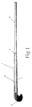
- the hockey stick 1 is comprised of a head 2, a stem 3, a handle 4 and a bead 5 showing a division between the parts 3 and 4.
- the stem 3 includes a slot 6 substantially between the bead 5 and the head 2.
- the solid hockey stick shown in Figure 1 was moulded using the referred to Verton material produced by ICI and being type RF700-10EM, this being a 50 percent long glass reinforced nylon 66 material.
- Such a material has a specific gravity of 1.57.
- the length moulded was 940 mm, the volume was 546,103 cubic mm, the weight was 856 grams (30.2 ozs), maximum stress under an arbitrary 200 Newton force applied at 860 mm from a rigidly fixed handle end comprised 127.3 Mpa and a maximum deflection of 11.4 mm.
- this hockey stick while useful for some players, was not satisfactory for normal play by competition players recognising that a weight of something between 483 to 767 g (17 to 27 ozs) was necessary.
- the handle of most hockey sticks is the area of least stress in a normal game of hockey. As in the game of golf, the head of the stick does most of the work and is subject to the majority of abuse in a normal game.
- Players of hockey generally wrap towel binding around the outer handle of the stick to provide adequate grip and "feel". Provided the outer diameter of the handle remains inside a 50 mm diameter ring gauge there are no specific size requirements. As a result of this we have examined ways to core out the handle area to reduce weight and to shift the centre of gravity towards the striking area of the stick.
- the standard handle diameter is 20 mm and covers a distance of 360 mm on a 940 mm (37") stick
- ICI 940 mm
- This system identified by the Registered Trade Mark, "Cinpres” allows solid regions to be cored using a gas which is injected at the same time as the thermoplastic resin.
- the analysis looked at the effect of introducing a hole over a distance of 460 mm into the handle region of the stick.
- Various diameter holes were examined as well as slightly increasing the outer diameter of the handle to 21 mm to see the effect on the strength and deflection of the handle area (Embodiment 2).
- the results for embodiments 1 and 2 are shown in Tables 1 and 2 respectively.
- Embodiments 3 and 4 involved examining the use of two polymeric materials in the handle area. The intention was to mould a slot in the handle made from material identified by the Registered Trade Mark “Verton", and as a second operation, insert mould a low density foamed polymeric material into the slot area. This would have two effects:
- Embodiment 3 consisted of a 20 mm handle 4 with a 10 mm slot 7 and Embodiment 4 consisted of a 21 mm handle 4 with an 11 mm slot 7.
- Embodiments 3 and 4 Handle Dia (mm) Slot Width (mm) Weight Red'n Total Wt. Stress (MPa) Defl'n (mm) grams (ozs) grams (ozs) 20 10.0 94 (3.3) 764 (26.9) 158.5 14.1 21 11.0 99 (3.5) 778 (27.4) 132.7 11.3
- Embodiments 5 to 7 followed a similar theme to Embodiment 3 in that two materials were considered, one being a material identified by the Registered Trade Mark "Verton" and the other being a low density foamed polymeric material.
- Verton Registered Trade Mark
- Embodiment 5 consists of a cross 8 in which both arms 9 have a width of 6.0 mm.
- Embodiment 6 is similar to Embodiment 4 but the arms 9 are both 4.0 mm in width.
- Embodiment 7 has one arm 9 of 6.0 mm and one arm 9 of 4.0 mm. In all three embodiments the handle diameter is 20 mm and the cross diameter is 16 mm.
- Table 4 shows the results of the three Embodiments.
- Embodiments 5, 6 and 7 Handle Dia (mm) Embodiment Weight Red'n Total Wt. Stress (MPa) Defl'n (mm) grams (ozs) grams (ozs) 20 5 69 (2.43) 789 (27.77) 385.9 43.1 20 6 89.7 (3.16) 768 (27.04) 577.9 64.5 20 7 77.8 (2.74) 780 (27.46) 408.7 45.6
- Embodiment 8 represents the base embodiment to which comparisons are made.
- the stem 3 is 45 mm wide across the front face 11 and is 20 mm thick from front face 11 to back 12, the groove 10 has a radius of 7.5 mm.
- the ridges 13 either side of the groove 10 have a flat top 15 with curved edges 16 of radius of 5.0 mm.
- the curves 14 at either side of the front face have a radius of curvature of 3.0 mm.
- the cross-sectional area is 670.565 mm 2 .
- the head, or contact area of the stick is the most important part in normal play.
- the size of this region is kept as large as permitted by the regulations of the game.
- the proposed design has a bulbous head shape which concentrates weight and the centre of gravity of the stick towards the contact area.
- the maximum stress value with a typical article in which them is a 200 Newton force applied at a 500 mm distance from a rigid support holding the stem will be approximately 150 Mpa.
- the hockey stick 1 is comprised of, in conventional manner, a head 2 with a gate location at an inner step part 15.
- a handle 4 and a stem 3 are separated by a bead 5.
- the plastics material is comprised of a plastics material available from the company ICI and similar to that which is sold under the trade mark "Verton (RF-700-10 EM)" with however a reduced long fibreglass content so that the fibreglass total comprises 35% by weight of the total weight of the material.
- the plastics material is comprised of nylon 66.
- the foaming or blowing agent which is used is known as "Hydrocerol" and the quantity of this material is such that the weight of the plastics is reduced subsequent to foaming within the mould to approximately 80% of the total weight.
- the plastics material is first prepared and the blowing agent Hydrocerol is mixed and held in a holding container under pressure so that whereas the blowing agent has effected a release of gas pressure, this has not caused any substantial foaming because of the maintenance of the pressure.
- results of the technique are such that for the first time there has been able to be made by the process of injection moulding a hockey stick which provides for an extremely strong surface skin which substantially resists abrasion and therefore provides long life for a purchaser but perhaps even more importantly, the all up weight of a hockey stick which still is within reasonable dimensions of size can be manufactured to be within the range required by international hockey players and in accord with appropriate international rules.
- the all up weight of a stick can be varied so that selected weights such as a 596 g (21 ounce) or a 625 g (22 ounce) or even perhaps a 138 g (26 ounce) stick can be made but in every case, having very adequate balance between the various parts of the stick in weight and finally being sufficiently strong so that they will not readily fracture if subjected to impact at various parts against other sticks or the ground or other obstacles.
- the total amount of plastics material has been reduced by approximately 20% by weight by reason of the gaseous infusion and the skin at the lower end (that is around the hook) is approximately 2 mm thick and substantially consolidated part whereas at the handle the skin is still approximately 2 mm thick but this has been reduced from a solid compacted material to one in which there is a substantial infusion of approximately 5 to 10% of gaseous infusion.
- the quantity of blowing agent in the plastics material can be varied and the range of perhaps 0.121% of blowing agent is possible although 0.25% by weight of the blowing agent is a preferred quantity.
Landscapes
- Health & Medical Sciences (AREA)
- General Health & Medical Sciences (AREA)
- Physical Education & Sports Medicine (AREA)
- Manufacturing & Machinery (AREA)
- Mechanical Engineering (AREA)
- Engineering & Computer Science (AREA)
- Injection Moulding Of Plastics Or The Like (AREA)
- Automatic Cycles, And Cycles In General (AREA)
- Low-Molecular Organic Synthesis Reactions Using Catalysts (AREA)
- Processing Of Solid Wastes (AREA)
- Catalysts (AREA)
- Organic Low-Molecular-Weight Compounds And Preparation Thereof (AREA)
- Manufacture Of Porous Articles, And Recovery And Treatment Of Waste Products (AREA)
- Laminated Bodies (AREA)
Abstract
Description
| Embodiment 1 | ||||||||
| Handle Dia (mm) | Hole Dia (mm) | Weight Red'n | Total Wt. | Wall Thick. (mm) | Stress (MPa) | Defl'n (mm) | ||
| grams | (ozs) | grams | (ozs) | |||||
| 20 | 0 | 0 | 0 | 856 | (30.2) | 10 | 127.3 | 11.4 |
| 20 | 5 | 14 | (0.5) | 843 | (29.7) | 7.5 | 127.8 | 11.4 |
| 20 | 8 | 37 | (1.3) | 824 | (29.0) | 6 | 130.7 | 11.7 |
| 20 | 10 | 57 | (2.0) | 801 | (28.2) | 5 | 135.8 | 12.1 |
| 20 | 12 | 82 | (2.9) | 778 | (27.4) | 4 | 146.3 | 13.1 |
| 20 | 14 | 111 | (3.9) | 747 | (26.3) | 3 | 167.6 | 15.0 |
| 20 | 15 | 128 | (4.5) | 730 | (25.7) | 2.5 | 186.3 | 16.6 |
| 20 | 16 | 145 | (5.1) | 713 | (25.1) | 2 | 215.7 | 19.3 |
| | ||||||||
| Handle Dia (mm) | Hole Dia (mm) | Weight Red'n | Total Wt. | Wall Thick (mm) | Stress (MPa) | Defl'n (mm) | ||
| grams | (ozs) | grams | (ozs) | |||||
| 21 | 0 | -23 | (-0.8) | 883 | (31.1) | 10.5 | 104.7 | 9.4 |
| 21 | 5 | -8.5 | (-0.3) | 585 | (20.6) | 8 | 105.1 | 9.4 |
| 21 | 8 | 14 | (0.5) | 846 | (29.8) | 6.5 | 107.0 | 9.6 |
| 21 | 10 | 34 | (1.2) | 826 | (29.1) | 5.5 | 110.4 | 9.9 |
| 21 | 12 | 60 | (2.1) | 801 | (28.2) | 4.5 | 117.3 | 10.5 |
| 21 | 14 | 88 | (3.1) | 770 | (27.1) | 3.5 | 130.5 | 11.7 |
| 21 | 15 | 105 | (3.7) | 755 | (26.6) | 3 | 141.6 | 12.6 |
| 21 | 16 | 122 | (4.3) | 736 | (25.9) | 2.5 | 158.0 | 14.1 |
| Embodiments 3 and 4 | |||||||
| Handle Dia (mm) | Slot Width (mm) | Weight Red'n | Total Wt. | Stress (MPa) | Defl'n (mm) | ||
| grams | (ozs) | grams | (ozs) | ||||
| 20 | 10.0 | 94 | (3.3) | 764 | (26.9) | 158.5 | 14.1 |
| 21 | 11.0 | 99 | (3.5) | 778 | (27.4) | 132.7 | 11.3 |
| | |||||||
| Handle Dia (mm) | Embodiment | Weight Red'n | Total Wt. | Stress (MPa) | Defl'n (mm) | ||
| grams | (ozs) | grams | (ozs) | ||||
| 20 | 5 | 69 | (2.43) | 789 | (27.77) | 385.9 | 43.1 |
| 20 | 6 | 89.7 | (3.16) | 768 | (27.04) | 577.9 | 64.5 |
| 20 | 7 | 77.8 | (2.74) | 780 | (27.46) | 408.7 | 45.6 |
-
Embodiment 9 - Remove 1 mm from the
front face 11 thereby making the thickness of the stick 19 mm -
Embodiment 10 - Move the centre of curvature of the
groove 10 towards thefront face 11 by 0.5 mm -
Embodiment 11 - Increase the radius of the
groove 10 to 8.0 mm and reduce the radius of theridges 13 to 4.5 mm -
Embodiment 12 - As in
Embodiment 11 but change the radius of theridge 13 to 6.0 mm -
Embodiment 13 - As in
Embodiment 12 but change the radius of theridge 13 to 5.0 mm.
| Embodiment | Area (mm2) | Weight Red'n | Total Wt | Stress (MPa) | Defl'n (mm-4) | ||
| grams | (ozs) | grams | (ozs) | ||||
| 8 | 670.565 | 0 | (0) | 856 | (30.2) | 59.8 | 4.6 |
| 9 | 628.226 | 20 | (0.7) | 835 | (29.5) | 66.9 | 5.4 |
| 10 | 654.077 | 8.5 | (0.3) | 849 | (30.0) | 60.4 | 4.6 |
| 11 | 632.162 | 17 | (0.6) | 838 | (29.6) | 63.0 | 4.8 |
| 12 | 626.215 | 20 | (0.7) | 835 | (29.5) | 66.8 | 5.0 |
| 13 | 598.559 | 34 | (1.2) | 821 | (29.0) | 73.0 | 5.4 |
Claims (25)
- A hockey stick (1) consisting of a head (2), a stem (3) the rear of the stem (3) having one or more grooves formed therein (10; 6), and a handle (4), comprising moulded plastics material, characterised in that the hockey stick comprises an outer skin region of a plastics material and a region of foamed plastics material contained by the outer skin, that the density of the head (2) and of the stem (3) is greater in the outer skin region than in the region contained by the outer skin and that the density of the outer skin region of the head (2) and lower portion of the stem (3) is greater than, and in the upper portion of the handle is less than, the average density of the outer skin.
- A hockey stick as claimed in Claim 1, characterised in that the groove or grooves (10; 6) are of 'U' shaped cross-section and their length extends parallel to the length of the stem (3) of the hockey stick.
- A hockey stick as claimed in Claim 1, characterised in that the groove or grooves (10; 6) are moulded in the stem (3) of the hockey stick.
- A hockey stick as claimed in any one of Claims 1 to 3, characterised by a hollow core extending within at least part of its length.
- A hockey stick as claimed in Claim 4, characterised in that the hollow core is contained primarily in the handle (4) of the hockey stick and is coaxial with the axis of the handle (4).
- A hockey stick as claimed in Claim 5, characterised in that the hollow core is of substantially circular cross-section.
- A hockey stick as claimed in any one of Claims 1 to 3, characterised in that the handle (4) of the hockey stick consists of a moulded shape (7, 8) interlocked, infused or surrounded by a further plastics material which provides a gripping shape by which the hockey stick can be gripped.
- A hockey stick as claimed in Claim 7, characterised in that the moulded shape is of star cross-section (8), of elliptical cross-section, rectangular cross-section or of triangular cross-section or is a slot (7) or comprises a plurality of circular apertures at spaced intervals along the handle (4).
- A hockey stick as claimed in any one of the preceding claims, characterised in that the outer skin of plastics material and the foamed plastics material are of different chemical composition.
- A hockey stick as claimed in any one of Claims 1 to 8, characterised in that the outer skin of plastics material and the foamed plastics material are of the same chemical composition but are of different densities.
- A hockey stick as claimed in any one of the preceding claims characterised in that the plastics material(s) is/are of thermoplastic type.
- A hockey stick as claimed in Claim 11, characterised in that the plastics material(s) is/are nylon or polypropylene.
- A hockey stick as claimed in any one of the preceding claims characterised in that the plastics material(s) is/are reinforced with randomly oriented fibre reinforcement.
- A hockey stick as claimed in Claim 13, characterised in that the reinforcement comprises glass, carbon or aramid fibres.
- A hockey stick as claimed in Claim 13 or 14, characterised in that the length of the fibre reinforcement lies in the range of 1 mm to 20 mm.
- A hockey stick as claimed in Claim 15, characterised in that the length of the fibre reinforcement lies in the range of 4 mm to 12 mm.
- A hockey stick as claimed in Claim 16, characterised in that the fibre reinforcement has an average length of 8 mm.
- A hockey stick as claimed in any one of Claims 13 to 17, characterised in that the total weight of the fibre reinforcement lies in the range of 60% to 90% of the total weight of the fibre reinforced plastics material.
- A hockey stick as claimed in Claim 18, characterised in that the total weight of the fibre reinforcement is approximately 80% of the total weight of the fibre reinforced plastics material.
- A hockey stick as claimed in any one of the preceding claims, characterised in that the density of the foamed plastics material is approximately 80% of that which would be the case if the plastics material were not foamed.
- A hockey stick as claimed in any one of the preceding claims, characterised in that the handle (4) and the stem (3) are at least partially wrapped with a material to aid the grip of a user of the hockey stick.
- A method of manufacture of a hockey stick of plastics material which comprises injecting a plastics material into a mould, characterised in that a foaming or blowing agent is added to the plastics material prior to injecting thereof into the mould, that the plastics material is gated into the mould at a location which comprises the inner part of the hook shape at the head (2) of the hockey stick, that a gaseous fluid is injected into the mould for a selected period whilst injecting the plastics material into the mould, thereby forming a hockey stick in which the density of the head (2) and of the stem (3) is greater in the outer skin region than in the region contained by the outer skin and the density of the outer skin region of the head (2) and lower portion of the stem (3) is greater than, and in the upper portion of the handle is less than, the average density of the outer skin, and that a groove (10; 6) is formed in the rear of the stem (3) of the hockey stick during the moulding process or subsequent thereto.
- A method as claimed in Claim 22, characterised in that the plastics material is of thermoplastic type.
- A method as claimed in Claim 23, characterised in that the plastics material is nylon or propylene.
- A method as claimed in any one of Claims 22 to 24, characterised in that after manufacture the hockey stick is immersed in water of a temperature in the range from 0° Celsius to 100° Celsius.
Applications Claiming Priority (7)
| Application Number | Priority Date | Filing Date | Title |
|---|---|---|---|
| AU7890/89 | 1989-12-15 | ||
| AUPJ789089 | 1989-12-15 | ||
| AUPJ921490 | 1990-03-19 | ||
| AU9214/90 | 1990-03-19 | ||
| AU1807/90 | 1990-08-17 | ||
| AUPK180790 | 1990-08-17 | ||
| PCT/AU1990/000582 WO1991008803A1 (en) | 1989-12-15 | 1990-12-07 | Hockey stick |
Publications (3)
| Publication Number | Publication Date |
|---|---|
| EP0504230A1 EP0504230A1 (en) | 1992-09-23 |
| EP0504230A4 EP0504230A4 (en) | 1992-12-02 |
| EP0504230B1 true EP0504230B1 (en) | 1998-07-08 |
Family
ID=27157534
Family Applications (1)
| Application Number | Title | Priority Date | Filing Date |
|---|---|---|---|
| EP91900671A Expired - Lifetime EP0504230B1 (en) | 1989-12-15 | 1990-12-07 | Hockey stick |
Country Status (6)
| Country | Link |
|---|---|
| EP (1) | EP0504230B1 (en) |
| JP (1) | JPH05504493A (en) |
| AT (1) | ATE168028T1 (en) |
| CA (1) | CA2071859A1 (en) |
| DE (1) | DE69032470D1 (en) |
| WO (1) | WO1991008803A1 (en) |
Cited By (5)
| Publication number | Priority date | Publication date | Assignee | Title |
|---|---|---|---|---|
| US7097577B2 (en) | 2000-09-15 | 2006-08-29 | Jas. D. Easton, Inc. | Hockey stick |
| US7144343B2 (en) | 2000-01-07 | 2006-12-05 | Jas. D. Easton, Inc. | Hockey stick |
| US7232386B2 (en) | 2003-05-15 | 2007-06-19 | Easton Sports, Inc. | Hockey stick |
| US7914403B2 (en) | 2008-08-06 | 2011-03-29 | Easton Sports, Inc. | Hockey stick |
| US7963868B2 (en) | 2000-09-15 | 2011-06-21 | Easton Sports, Inc. | Hockey stick |
Families Citing this family (7)
| Publication number | Priority date | Publication date | Assignee | Title |
|---|---|---|---|---|
| GB2383292A (en) * | 2001-12-20 | 2003-06-25 | Adrian Joseph Lloyd | Improvements relating to grab handles |
| DK174823B1 (en) | 2002-04-23 | 2003-12-08 | Hp Ind As | Method of thermoplastic molding of a tubular workpiece |
| WO2007051891A1 (en) * | 2005-11-03 | 2007-05-10 | Exel Oyj | Nordic walking pole or shaft for a floorball stick or an implement and method for manufacturing the pole or the shaft |
| DE102008017377A1 (en) * | 2008-04-05 | 2009-10-08 | Röchling Technische Teile KG | Lightweight component and method for producing this |
| RU178415U1 (en) * | 2016-04-14 | 2018-04-03 | Анна Александровна Сергеева | Hockey stick |
| US12029951B2 (en) | 2017-12-14 | 2024-07-09 | Bauer Hockey, Llc | Hockey stick and blade for hockey stick |
| US12042706B2 (en) * | 2017-12-14 | 2024-07-23 | Bauer Hockey, Llc | Hockey stick with variable stiffness blade |
Family Cites Families (12)
| Publication number | Priority date | Publication date | Assignee | Title |
|---|---|---|---|---|
| GB1121051A (en) * | 1966-02-08 | 1968-07-24 | Carlton Tyre Saving Co Ltd | Improvements in or relating to striking instruments incorporating shock absorbing means |
| GB1259467A (en) * | 1968-11-14 | 1972-01-05 | ||
| DE2005952A1 (en) * | 1970-02-10 | 1971-10-21 | Silkok-Schwelm, Gesellschaft für Kunststoffverarbeitung, 5830 Schwelm | Plastics golf or hockey stick |
| CH570867A5 (en) * | 1973-09-19 | 1975-12-31 | Lo Sfruttamento Di Brevetti Sa | |
| AU522070B2 (en) * | 1977-03-17 | 1982-05-13 | Motley Manufacturing Agencies Pty. Ltd. | Plastic hockey stick |
| DE2845735A1 (en) * | 1978-10-20 | 1980-04-30 | Inplast Handels Gmbh | HOCKEY RACKET |
| FR2487208A1 (en) * | 1980-07-07 | 1982-01-29 | Boniface Jacques | Hockey stick with head covered by a durable plastic - pref. polypropylene sheathed with polyurethane and moulded in situ |
| GB2139548B (en) * | 1983-05-11 | 1986-11-19 | James Watson Hendry | Injection moulding |
| EP0172564A3 (en) * | 1984-08-21 | 1987-10-14 | Loxton Manufacturers (Pvt) Ltd | Sporting equipment, such as hockey sticks, cricket bats and the like, and method of manufacturing such items |
| GB8508916D0 (en) * | 1985-04-04 | 1985-05-09 | Dunlop Ltd | Making striking implements |
| GB2201117B (en) * | 1987-02-20 | 1990-04-18 | Charng Inn Aluminum Industry C | Manufacturing process for composite hockey sticks |
| GB8706204D0 (en) * | 1987-03-16 | 1987-04-23 | Peerless Cinpres Ltd | Injection moulding apparatus |
-
1990
- 1990-12-07 JP JP3501137A patent/JPH05504493A/en active Pending
- 1990-12-07 WO PCT/AU1990/000582 patent/WO1991008803A1/en not_active Ceased
- 1990-12-07 DE DE69032470T patent/DE69032470D1/en not_active Expired - Lifetime
- 1990-12-07 CA CA002071859A patent/CA2071859A1/en not_active Abandoned
- 1990-12-07 AT AT91900671T patent/ATE168028T1/en not_active IP Right Cessation
- 1990-12-07 EP EP91900671A patent/EP0504230B1/en not_active Expired - Lifetime
Cited By (11)
| Publication number | Priority date | Publication date | Assignee | Title |
|---|---|---|---|---|
| US7144343B2 (en) | 2000-01-07 | 2006-12-05 | Jas. D. Easton, Inc. | Hockey stick |
| US7422532B2 (en) | 2000-01-07 | 2008-09-09 | Easton Sports, Inc. | Hockey stick |
| US7097577B2 (en) | 2000-09-15 | 2006-08-29 | Jas. D. Easton, Inc. | Hockey stick |
| US7789778B2 (en) | 2000-09-15 | 2010-09-07 | Easton Sports, Inc. | Hockey stick |
| US7850553B2 (en) | 2000-09-15 | 2010-12-14 | Easton Sports, Inc. | Hockey stick |
| US7963868B2 (en) | 2000-09-15 | 2011-06-21 | Easton Sports, Inc. | Hockey stick |
| US8216096B2 (en) | 2000-09-15 | 2012-07-10 | Easton Sports, Inc. | Hockey stick |
| US8517868B2 (en) | 2000-09-15 | 2013-08-27 | Easton Sports, Inc. | Hockey stick |
| US7232386B2 (en) | 2003-05-15 | 2007-06-19 | Easton Sports, Inc. | Hockey stick |
| US7862456B2 (en) | 2003-05-15 | 2011-01-04 | Easton Sports, Inc. | Hockey stick |
| US7914403B2 (en) | 2008-08-06 | 2011-03-29 | Easton Sports, Inc. | Hockey stick |
Also Published As
| Publication number | Publication date |
|---|---|
| JPH05504493A (en) | 1993-07-15 |
| EP0504230A1 (en) | 1992-09-23 |
| CA2071859A1 (en) | 1991-06-16 |
| DE69032470D1 (en) | 1998-08-13 |
| EP0504230A4 (en) | 1992-12-02 |
| WO1991008803A1 (en) | 1991-06-27 |
| ATE168028T1 (en) | 1998-07-15 |
Similar Documents
| Publication | Publication Date | Title |
|---|---|---|
| KR830001507B1 (en) | Competition Racket Frames | |
| EP0504230B1 (en) | Hockey stick | |
| CA1273662A (en) | Lacrosse stick having open sidewall structure | |
| US4739994A (en) | Lacrosse stick with graphite-loaded handle | |
| US5269532A (en) | Lacrosse stick head | |
| US5143571A (en) | Method of molding a golf club head | |
| CA2099391A1 (en) | Golf clubhead with multi-material soleplate | |
| NZ215690A (en) | Head construction of a golf club | |
| US3981504A (en) | Glass-carbon reinforced foamed resin tennis racket frame | |
| US4360202A (en) | CFRP or FRP made badminton racket frame | |
| EP0471237A1 (en) | A method for manufacturing a shock resistant tool of fiber reinforced resin | |
| US5277866A (en) | Method of injection molding a hollow golf club | |
| AU682953B2 (en) | Takraw balls | |
| US5922255A (en) | Method of manufacturing a racket frame and throat | |
| AU6966291A (en) | Hockey stick | |
| JPH02191475A (en) | Golf club head | |
| EP0401498A2 (en) | Hollow, elongate mouldings | |
| WO1995028206A1 (en) | Takraw balls | |
| JP3172453B2 (en) | Racket frame | |
| GB1594674A (en) | Sporting equipment | |
| JPS61255677A (en) | Golf club head | |
| JPS6156670A (en) | Golf club head | |
| JPH0412773A (en) | Golf club head made of fiber reinforced metal | |
| Froes et al. | Third International Conference On The Engineering Of Sport Research, Development And Innovation | |
| KR20010000196U (en) | a bat |
Legal Events
| Date | Code | Title | Description |
|---|---|---|---|
| PUAI | Public reference made under article 153(3) epc to a published international application that has entered the european phase |
Free format text: ORIGINAL CODE: 0009012 |
|
| 17P | Request for examination filed |
Effective date: 19920622 |
|
| AK | Designated contracting states |
Kind code of ref document: A1 Designated state(s): AT BE CH DE DK ES FR GB GR IT LI LU NL SE |
|
| A4 | Supplementary search report drawn up and despatched |
Effective date: 19921013 |
|
| AK | Designated contracting states |
Kind code of ref document: A4 Designated state(s): AT BE CH DE DK ES FR GB GR IT LI LU NL SE |
|
| 17Q | First examination report despatched |
Effective date: 19940216 |
|
| GRAG | Despatch of communication of intention to grant |
Free format text: ORIGINAL CODE: EPIDOS AGRA |
|
| GRAG | Despatch of communication of intention to grant |
Free format text: ORIGINAL CODE: EPIDOS AGRA |
|
| GRAH | Despatch of communication of intention to grant a patent |
Free format text: ORIGINAL CODE: EPIDOS IGRA |
|
| GRAH | Despatch of communication of intention to grant a patent |
Free format text: ORIGINAL CODE: EPIDOS IGRA |
|
| GRAA | (expected) grant |
Free format text: ORIGINAL CODE: 0009210 |
|
| AK | Designated contracting states |
Kind code of ref document: B1 Designated state(s): AT BE CH DE DK ES FR GB GR IT LI LU NL SE |
|
| PG25 | Lapsed in a contracting state [announced via postgrant information from national office to epo] |
Ref country code: IT Free format text: LAPSE BECAUSE OF FAILURE TO SUBMIT A TRANSLATION OF THE DESCRIPTION OR TO PAY THE FEE WITHIN THE PRESCRIBED TIME-LIMIT;WARNING: LAPSES OF ITALIAN PATENTS WITH EFFECTIVE DATE BEFORE 2007 MAY HAVE OCCURRED AT ANY TIME BEFORE 2007. THE CORRECT EFFECTIVE DATE MAY BE DIFFERENT FROM THE ONE RECORDED. Effective date: 19980708 Ref country code: ES Free format text: THE PATENT HAS BEEN ANNULLED BY A DECISION OF A NATIONAL AUTHORITY Effective date: 19980708 Ref country code: NL Free format text: LAPSE BECAUSE OF FAILURE TO SUBMIT A TRANSLATION OF THE DESCRIPTION OR TO PAY THE FEE WITHIN THE PRESCRIBED TIME-LIMIT Effective date: 19980708 Ref country code: LI Free format text: LAPSE BECAUSE OF FAILURE TO SUBMIT A TRANSLATION OF THE DESCRIPTION OR TO PAY THE FEE WITHIN THE PRESCRIBED TIME-LIMIT Effective date: 19980708 Ref country code: FR Free format text: LAPSE BECAUSE OF FAILURE TO SUBMIT A TRANSLATION OF THE DESCRIPTION OR TO PAY THE FEE WITHIN THE PRESCRIBED TIME-LIMIT Effective date: 19980708 Ref country code: CH Free format text: LAPSE BECAUSE OF FAILURE TO SUBMIT A TRANSLATION OF THE DESCRIPTION OR TO PAY THE FEE WITHIN THE PRESCRIBED TIME-LIMIT Effective date: 19980708 Ref country code: BE Free format text: LAPSE BECAUSE OF FAILURE TO SUBMIT A TRANSLATION OF THE DESCRIPTION OR TO PAY THE FEE WITHIN THE PRESCRIBED TIME-LIMIT Effective date: 19980708 Ref country code: AT Free format text: LAPSE BECAUSE OF FAILURE TO SUBMIT A TRANSLATION OF THE DESCRIPTION OR TO PAY THE FEE WITHIN THE PRESCRIBED TIME-LIMIT Effective date: 19980708 Ref country code: GR Free format text: LAPSE BECAUSE OF NON-PAYMENT OF DUE FEES Effective date: 19980708 |
|
| REF | Corresponds to: |
Ref document number: 168028 Country of ref document: AT Date of ref document: 19980715 Kind code of ref document: T |
|
| REG | Reference to a national code |
Ref country code: CH Ref legal event code: EP |
|
| REF | Corresponds to: |
Ref document number: 69032470 Country of ref document: DE Date of ref document: 19980813 |
|
| PG25 | Lapsed in a contracting state [announced via postgrant information from national office to epo] |
Ref country code: DK Free format text: LAPSE BECAUSE OF FAILURE TO SUBMIT A TRANSLATION OF THE DESCRIPTION OR TO PAY THE FEE WITHIN THE PRESCRIBED TIME-LIMIT Effective date: 19981008 Ref country code: SE Free format text: LAPSE BECAUSE OF FAILURE TO SUBMIT A TRANSLATION OF THE DESCRIPTION OR TO PAY THE FEE WITHIN THE PRESCRIBED TIME-LIMIT Effective date: 19981008 |
|
| PG25 | Lapsed in a contracting state [announced via postgrant information from national office to epo] |
Ref country code: DE Free format text: LAPSE BECAUSE OF FAILURE TO SUBMIT A TRANSLATION OF THE DESCRIPTION OR TO PAY THE FEE WITHIN THE PRESCRIBED TIME-LIMIT Effective date: 19981009 |
|
| NLV1 | Nl: lapsed or annulled due to failure to fulfill the requirements of art. 29p and 29m of the patents act | ||
| EN | Fr: translation not filed | ||
| PG25 | Lapsed in a contracting state [announced via postgrant information from national office to epo] |
Ref country code: LU Free format text: LAPSE BECAUSE OF NON-PAYMENT OF DUE FEES Effective date: 19981207 Ref country code: GB Free format text: LAPSE BECAUSE OF NON-PAYMENT OF DUE FEES Effective date: 19981207 |
|
| REG | Reference to a national code |
Ref country code: CH Ref legal event code: PL |
|
| PLBE | No opposition filed within time limit |
Free format text: ORIGINAL CODE: 0009261 |
|
| STAA | Information on the status of an ep patent application or granted ep patent |
Free format text: STATUS: NO OPPOSITION FILED WITHIN TIME LIMIT |
|
| 26N | No opposition filed | ||
| GBPC | Gb: european patent ceased through non-payment of renewal fee |
Effective date: 19981207 |