EP0471237A1 - A method for manufacturing a shock resistant tool of fiber reinforced resin - Google Patents
A method for manufacturing a shock resistant tool of fiber reinforced resin Download PDFInfo
- Publication number
- EP0471237A1 EP0471237A1 EP91112824A EP91112824A EP0471237A1 EP 0471237 A1 EP0471237 A1 EP 0471237A1 EP 91112824 A EP91112824 A EP 91112824A EP 91112824 A EP91112824 A EP 91112824A EP 0471237 A1 EP0471237 A1 EP 0471237A1
- Authority
- EP
- European Patent Office
- Prior art keywords
- fiber
- resin
- shock resistant
- reinforcing
- tool
- Prior art date
- Legal status (The legal status is an assumption and is not a legal conclusion. Google has not performed a legal analysis and makes no representation as to the accuracy of the status listed.)
- Granted
Links
Images


Classifications
-
- C—CHEMISTRY; METALLURGY
- C08—ORGANIC MACROMOLECULAR COMPOUNDS; THEIR PREPARATION OR CHEMICAL WORKING-UP; COMPOSITIONS BASED THEREON
- C08J—WORKING-UP; GENERAL PROCESSES OF COMPOUNDING; AFTER-TREATMENT NOT COVERED BY SUBCLASSES C08B, C08C, C08F, C08G or C08H
- C08J5/00—Manufacture of articles or shaped materials containing macromolecular substances
- C08J5/04—Reinforcing macromolecular compounds with loose or coherent fibrous material
-
- A—HUMAN NECESSITIES
- A42—HEADWEAR
- A42B—HATS; HEAD COVERINGS
- A42B3/00—Helmets; Helmet covers ; Other protective head coverings
- A42B3/04—Parts, details or accessories of helmets
- A42B3/06—Impact-absorbing shells, e.g. of crash helmets
-
- A—HUMAN NECESSITIES
- A42—HEADWEAR
- A42B—HATS; HEAD COVERINGS
- A42B3/00—Helmets; Helmet covers ; Other protective head coverings
- A42B3/04—Parts, details or accessories of helmets
- A42B3/06—Impact-absorbing shells, e.g. of crash helmets
- A42B3/062—Impact-absorbing shells, e.g. of crash helmets with reinforcing means
- A42B3/063—Impact-absorbing shells, e.g. of crash helmets with reinforcing means using layered structures
-
- A—HUMAN NECESSITIES
- A63—SPORTS; GAMES; AMUSEMENTS
- A63B—APPARATUS FOR PHYSICAL TRAINING, GYMNASTICS, SWIMMING, CLIMBING, OR FENCING; BALL GAMES; TRAINING EQUIPMENT
- A63B49/00—Stringed rackets, e.g. for tennis
- A63B49/02—Frames
- A63B49/10—Frames made of non-metallic materials, other than wood
-
- A—HUMAN NECESSITIES
- A63—SPORTS; GAMES; AMUSEMENTS
- A63B—APPARATUS FOR PHYSICAL TRAINING, GYMNASTICS, SWIMMING, CLIMBING, OR FENCING; BALL GAMES; TRAINING EQUIPMENT
- A63B60/00—Details or accessories of golf clubs, bats, rackets or the like
- A63B60/54—Details or accessories of golf clubs, bats, rackets or the like with means for damping vibrations
-
- B—PERFORMING OPERATIONS; TRANSPORTING
- B29—WORKING OF PLASTICS; WORKING OF SUBSTANCES IN A PLASTIC STATE IN GENERAL
- B29C—SHAPING OR JOINING OF PLASTICS; SHAPING OF MATERIAL IN A PLASTIC STATE, NOT OTHERWISE PROVIDED FOR; AFTER-TREATMENT OF THE SHAPED PRODUCTS, e.g. REPAIRING
- B29C70/00—Shaping composites, i.e. plastics material comprising reinforcements, fillers or preformed parts, e.g. inserts
- B29C70/04—Shaping composites, i.e. plastics material comprising reinforcements, fillers or preformed parts, e.g. inserts comprising reinforcements only, e.g. self-reinforcing plastics
- B29C70/06—Fibrous reinforcements only
- B29C70/10—Fibrous reinforcements only characterised by the structure of fibrous reinforcements, e.g. hollow fibres
-
- B—PERFORMING OPERATIONS; TRANSPORTING
- B62—LAND VEHICLES FOR TRAVELLING OTHERWISE THAN ON RAILS
- B62K—CYCLES; CYCLE FRAMES; CYCLE STEERING DEVICES; RIDER-OPERATED TERMINAL CONTROLS SPECIALLY ADAPTED FOR CYCLES; CYCLE AXLE SUSPENSIONS; CYCLE SIDECARS, FORECARS, OR THE LIKE
- B62K19/00—Cycle frames
- B62K19/02—Cycle frames characterised by material or cross-section of frame members
- B62K19/16—Cycle frames characterised by material or cross-section of frame members the material being wholly or mainly of plastics
-
- B—PERFORMING OPERATIONS; TRANSPORTING
- B62—LAND VEHICLES FOR TRAVELLING OTHERWISE THAN ON RAILS
- B62K—CYCLES; CYCLE FRAMES; CYCLE STEERING DEVICES; RIDER-OPERATED TERMINAL CONTROLS SPECIALLY ADAPTED FOR CYCLES; CYCLE AXLE SUSPENSIONS; CYCLE SIDECARS, FORECARS, OR THE LIKE
- B62K21/00—Steering devices
- B62K21/12—Handlebars; Handlebar stems
-
- A—HUMAN NECESSITIES
- A63—SPORTS; GAMES; AMUSEMENTS
- A63B—APPARATUS FOR PHYSICAL TRAINING, GYMNASTICS, SWIMMING, CLIMBING, OR FENCING; BALL GAMES; TRAINING EQUIPMENT
- A63B2208/00—Characteristics or parameters related to the user or player
- A63B2208/12—Characteristics or parameters related to the user or player specially adapted for children
-
- A—HUMAN NECESSITIES
- A63—SPORTS; GAMES; AMUSEMENTS
- A63B—APPARATUS FOR PHYSICAL TRAINING, GYMNASTICS, SWIMMING, CLIMBING, OR FENCING; BALL GAMES; TRAINING EQUIPMENT
- A63B2209/00—Characteristics of used materials
- A63B2209/02—Characteristics of used materials with reinforcing fibres, e.g. carbon, polyamide fibres
- A63B2209/023—Long, oriented fibres, e.g. wound filaments, woven fabrics, mats
-
- A—HUMAN NECESSITIES
- A63—SPORTS; GAMES; AMUSEMENTS
- A63B—APPARATUS FOR PHYSICAL TRAINING, GYMNASTICS, SWIMMING, CLIMBING, OR FENCING; BALL GAMES; TRAINING EQUIPMENT
- A63B2209/00—Characteristics of used materials
- A63B2209/02—Characteristics of used materials with reinforcing fibres, e.g. carbon, polyamide fibres
- A63B2209/026—Ratio fibres-total material
-
- B—PERFORMING OPERATIONS; TRANSPORTING
- B29—WORKING OF PLASTICS; WORKING OF SUBSTANCES IN A PLASTIC STATE IN GENERAL
- B29C—SHAPING OR JOINING OF PLASTICS; SHAPING OF MATERIAL IN A PLASTIC STATE, NOT OTHERWISE PROVIDED FOR; AFTER-TREATMENT OF THE SHAPED PRODUCTS, e.g. REPAIRING
- B29C67/00—Shaping techniques not covered by groups B29C39/00 - B29C65/00, B29C70/00 or B29C73/00
- B29C67/24—Shaping techniques not covered by groups B29C39/00 - B29C65/00, B29C70/00 or B29C73/00 characterised by the choice of material
- B29C67/246—Moulding high reactive monomers or prepolymers, e.g. by reaction injection moulding [RIM], liquid injection moulding [LIM]
-
- B—PERFORMING OPERATIONS; TRANSPORTING
- B29—WORKING OF PLASTICS; WORKING OF SUBSTANCES IN A PLASTIC STATE IN GENERAL
- B29K—INDEXING SCHEME ASSOCIATED WITH SUBCLASSES B29B, B29C OR B29D, RELATING TO MOULDING MATERIALS OR TO MATERIALS FOR MOULDS, REINFORCEMENTS, FILLERS OR PREFORMED PARTS, e.g. INSERTS
- B29K2025/00—Use of polymers of vinyl-aromatic compounds or derivatives thereof as moulding material
-
- B—PERFORMING OPERATIONS; TRANSPORTING
- B29—WORKING OF PLASTICS; WORKING OF SUBSTANCES IN A PLASTIC STATE IN GENERAL
- B29K—INDEXING SCHEME ASSOCIATED WITH SUBCLASSES B29B, B29C OR B29D, RELATING TO MOULDING MATERIALS OR TO MATERIALS FOR MOULDS, REINFORCEMENTS, FILLERS OR PREFORMED PARTS, e.g. INSERTS
- B29K2055/00—Use of specific polymers obtained by polymerisation reactions only involving carbon-to-carbon unsaturated bonds, not provided for in a single one of main groups B29K2023/00 - B29K2049/00, e.g. having a vinyl group, as moulding material
-
- C—CHEMISTRY; METALLURGY
- C08—ORGANIC MACROMOLECULAR COMPOUNDS; THEIR PREPARATION OR CHEMICAL WORKING-UP; COMPOSITIONS BASED THEREON
- C08J—WORKING-UP; GENERAL PROCESSES OF COMPOUNDING; AFTER-TREATMENT NOT COVERED BY SUBCLASSES C08B, C08C, C08F, C08G or C08H
- C08J2365/00—Characterised by the use of macromolecular compounds obtained by reactions forming a carbon-to-carbon link in the main chain; Derivatives of such polymers
Definitions
- the present invention relates to tools resistant to a mechanical shock and more particularly to tools likely to be subjected to a shock listed below.
- goods required to have a shock resistant performance are made of ABS resin, polycarbonate resin, fiber reinforced resin (FRP) formed by reinforcing thermoplastic resin with short fiber or fiber reinforced resin (FRP) formed by reinforcing thermosetting resin generally with chopped strand mat of glass.
- the chopped strand mat of glass may be replaced by continuous fiber, long fiber or short fiber consisting of glass fiber, carbon fiber, aramid fiber, boron fiber or ultra-high-molecular-weight polyethylene fiber.
- Unsaturated polyester resin is mainly used as matrix resin.
- the following methods are used to manufacture the above fiber reinforced resins formed by reinforcing thermosetting resin with chopped strand mat of glass: a half-hardened prepreg formed by impregnating fiber with resin is cut to an appropriate size and a configuration, and then, cut materials are laminated on each other in a die, then, heated under pressure so as to harden the resin; chopped strand and resin are sprayed up in a die and then hardened; reinforced fibers are laminated on a balloon-shaped die, then, the reinforcing fiber is impregnated with resin and then, hardened.
- shock resistant tools made of only ABS resin or polycarbonate resin do not have a favorable rigidity because they do not contain a reinforcing material.
- fiber reinforced resin (FRP) formed by reinforcing thermoplastic resin with short fiber has also an unfavorable rigidity.
- shock resistant performance of molded goods can be increased by using reinforcing fiber and matrix resin favorable in shock resistant performance and increasing the content percentage of reinforcing fiber. But it is uneasy to increase fiber content and the method for manufacturing the above shock resistant goods has problems.
- fiber content percentage can be increased by cutting the prepreg sheets having thermosetting resin impregnated therein to a certain configuration, laminating cut materials on a die, and heating them under pressure.
- the molded goods is inferior in shock resistant performance because thermosetting resin is inferior in shock resistant performance.
- this method has an unfavorable production cycle and moreover, the manufacturing cost is high.
- cyclopentadiene resin is used as matrix resin because it has a favorable shock resistant performance and increases fiber content percentage due to its low viscosity before polymerization takes place.
- Cyclopentadiene resin is injected into a die, by reaction injection molding method, in which reinforcing fiber is placed to obtain a shock resistant tool molded in a desired configuration.
- a shock resistant tool comprises fiber reinforced resin molded by reaction injection molding method using at least one of reinforcing fiber of ultra-high-molecular-weight polyethylene fiber, carbon fiber, glass fiber, aramid fiber, alumina fiber, silicon carbide fiber, steel fiber, amorphous metal fiber, organic fiber and/or a combination thereof as a reinforcing material; and cyclopentadiene resin as matrix resin.
- the reinforcing fiber as the fiber reinforced resin of the shock resistant tool, continuous fiber, long fiber or short fiber is used. When a high rigidity and a high strength are required, the continuous fiber or the long fiber is used.
- the reinforcing fiber cloth fiber, filament winding, a mat in random arrangement such as continuous strand mat are preferably used.
- fiber is contained in the shock resistant tool at more than 40% in a region in which fiber is required to be contained at the highest percentage.
- Reinforcing fiber is contained therein at a varied percentage depending on a region, i.e., a region to which shock is applied greatly contains the reinforcing fiber at a high percentage and a region to which shock is applied in a small extent contains the reinforcing fiber at a low percentage.
- the shock resistant tool is light and its production cost is reduced.
- a shoulder protector for use in football fiber is contained at 40% in shoulder and 20% in chest.
- nonwoven fiber is used in combination of the reinforcing fiber as the fiber reinforcing material. It is preferable that only nonwoven fiber is used in a region in which a high strength is not required or nonwoven fiber is used at a percentage higher than the reinforcing fiber.
- nonwoven cloth allowing a smooth flow of resin during a molding operation and reducing the weight of the shock resistant tool, thus reducing cost is distributed at a varied percentage according to a region.
- the flange of a baseball helmet consists of nonwoven cloth.
- the following materials are used as the nonwoven cloth to be distributed in the outer side of the fiber reinforced resin and the surface of the inner side and/or intermediate portion thereof: glass fiber paper, carbon fiber paper, polyester nonwoven cloth, nylon nonwoven cloth, vinyl nonwoven cloth, ultra-high molecular-weight polyethylene nonwoven cloth, PPS nonwoven cloth, acrylic fiber nonwoven cloth and the like.
- fiber density of the nonwoven cloth ranges from 1 to 35 vol% and more favorably from 2 to 20 vol% so that resin flows smoothly during a molding operation.
- one or more kinds of fibers containing ultra-high molecular-weight polyethylene fiber is used as the reinforcing fiber.
- Shock resistant tools molded in a die by the reaction injection molding method include sporting goods such as helmet, face-guard, pad, leg guards for protecting head, face, plastron, shoulder, elbow, knee and the like; racket frame such as tennis racket frame for use in ball games; helmets for protecting head from shock in riding car or bicycle and for construction work; vehicle frame including bicycle frame and bicycle handle, canoe frame for preventing breakage against a shock; and protecting wall, against machine tool, for preventing the transmission of a shock.
- the racket frame When a shock resistant tool is a racket frame, the racket frame contains ultra-high-molecular-weight polyethylene fiber at least 10 wt% in the reinforcing fiber and a resin layer including the nonwoven cloth in the inner portion, outer portion and/or intermediate portion of the fiber reinforced resin consisting of the cyclopentadiene resin reinforced with the fiber reinforcing material.
- reinforcing fiber and nonwoven cloth are provided in the outer side, inner side and/or the gap between reinforcing material layers.
- the material thus preformed is placed in a die.
- cyclopentadiene containing polymerization catalyst and initiator of polymerization is injected into the die, and the mixture is heated at a predetermined temperature, for example, lower than 130°C so as to mold it into crosslinked resin by two-solution injection molding method (RIM).
- RIM two-solution injection molding method
- the preformed material is compressed against the surface of the die with sheet-shaped rubber shaped into the configuration in conformity with that of the die and the preformed material, and extra resin is discharged from a resin discharge opening.
- fiber content percentage can be increased.
- the following methods are used: molding by means of a die; spray-up of short fiber and chopped strand mat; and molding by heating and pressure application of a reinforcing material to which a binder has been attached.
- cyclopentadiene resin dicyclopentadiene, dihydrodicyclopentadiene, tricyclopentadiene, tetracyclopentadiene, cyclopentadiene-methylpentadiene copolymer are used.
- halide of tungsten, molybdenum, tantalum; oxyhalide; oxide; organic ammonium salt are preferably used.
- organic metal compound mainly alkyl of metal of I through III groups of periodic table, compounds of alcohol, phenol or the like are preferably used.
- monoether and/or monoester of a glycol compound selected from alkylene glycol or polyalkylene glycol are preferably used as an activity adjusting agent.
- the die In injection molding in the die, the die is heated at 40 to 130°C and polymerization reaction takes place for one to five minutes.
- the material of a shock resistant tool is provided on a flexible core (internal pressure holding member) which conforms to the surface configuration of the die.
- a flexible core internal pressure holding member
- Tube-shaped or bag-shaped materials such as nylon, cellophane, rubber, polyester, polyether ketone or the like is preferably used.
- a shock resistant tool according to the present invention such as a racket frame or a helmet is formed in combination of reinforcing fiber and cyclopentadiene resin superior in shock resistant performance. Since cyclopentadiene resin to be used as matrix resin has a low melt viscosity, fiber can be contained at higher than 50%. Therefore, the shock resistant performance of the tool according to the present invention can be improved as compared with conventional ones. For example, comparing a helmet according to the present invention and a conventional helmet commercially available with each other, energy required to destroy the helmet according to the present invention is approximately twice as great as that required to destroy the conventional helmet. This data is obtained as a result of tests which is described later.
- shock resistant performance Compared with the shock resistant performance of conventional tools, in addition to shock resistant performance, vibration damping performance, chemical resistant property, and weather resistant property are improved.
- vibration damping performance is superior, so that vibration damping ratio can be made at a high percentage, namely, higher than 0.8%. Therefore, a tennis racket frame comprising the above mixture does not apply a great force to elbow, so that it is preferably used by a powerless player.
- Vibration damping characteristic is preferable by providing a layer consisting of 95% of matrix resin and 5% of nonwoven cloth, namely, a layer containing much amount of resin and a small amount of nonwoven cloth. According to this distribution of ultra-high-molecular-weight polyethylene fiber and cyclopentadiene resin, the external appearance of a tool is preferable.
- the material of the tool can be placed in a die by controlling the fiber angle, fiber amount, and fiber thickness.
- the molding cycle is preferable, and hence an efficient productivity can be obtained.
- Fig. 1 shows a shock resistant tennis racket frame 1 according to a first embodiment of the present invention. Its length ranges from 52cm to 68cm (68cm according to the first embodiment) and its weight ranges from 230g to 400g (335g according to the first embodiment).
- the vibration damping ratio of the tennis racket frame 1 is 0.8% which is greatly improved compared with conventional tennis rackets.
- the tennis racket frame 1 comprises a core nylon tube 2 and a fiber reinforced resin layer 3 consisting of cyclopentadiene resin containing continuous fiber, consisting of ultra-high molecular-weight polyethylene fiber and carbon fiber, formed in the periphery of the core nylon tube 2.
- the racket frame 1 is manufactured by two-solution reaction injection molding (RIM) method which will be described below.
- RIM reaction injection molding
- the core tube 2 is made of a nylon tube in the thickness of 100 ⁇ m and braided carbon fiber (article number: BC-7664-24 (20), manufactured by Toho Rayon Co., Ltd.) is arranged in the periphery of the core nylon tube 2 so that each braided carbon fiber makes 24° with the longitudinal direction of the tennis racket frame 1 and the weight of the braided carbon fiber is 40 wt%.
- Braided fiber consisting of ultra-high-molecular-weight polyethylene fiber (SK-60, manufactured by Toyobo Co., Ltd.) is provided so that the braided fiber makes 24° with the longitudinal direction of the tennis racket frame 1 and the weight of the braided carbon fiber is 20 wt%.
- the carbon fiber and ultra-high-molecular-weight polyethylene fiber are braided and cut so that the angle of the braided fiber makes the above-described angle, and they are preformed so that the configuration of the braided fiber conforms to that of the tennis racket frame 1.
- the preforming method is described later in the description of a baseball helmet according to a second embodiment.
- the preformed fiber reinforcing material is arranged on the periphery of the core nylon tube 2.
- the fiber reinforcing material is set in a die and the die is heated at 60°C. Then, the pressure in the die is reduced by a vacuum pump.
- dicyclopentadiene containing polymerizing catalyst and initiator of polymerization is placed in the die under pressure. That is, a desired amount of dicyclopentadiene is contained in two containers.
- Polymerizing catalyst is put into one container and an activator (initiator of polymerization) and an activity adjusting agent are put into the other container so as to prepare two stable reaction solutions.
- the reaction solutions are mixed with each other instantaneously by a mixing head of a two-solution reaction/injection molding device. The mixture is immediately injected into the die heated at 60°C under a low pressure.
- Fig. 3 shows a first modification of the tennis racket frame of the first embodiment.
- the tennis racket frame 1' comprises the core nylon tube 2, a fiber reinforced resin layer 3 consisting of cyclopentadiene resin containing continuous fiber consisting of ultra-high-molecular-weight polyethylene fiber formed in the periphery of the core nylon tube 2, and a nonwoven cloth containing layer 4 consisting of cyclopentadiene resin containing glass nonwoven cloth formed in the periphery of the fiber reinforced resin layer 3.
- the length and weight of the tennis racket frame 1' are similar to those of the first embodiment, and the vibration damping ratio thereof is 2.5% which is improved greatly compared with conventional ones.
- the method for manufacturing the tennis racket frame 1' having the nonwoven cloth containing layer 4 is almost same as that of the first embodiment.
- the first modification of the first embodiment is different from the first embodiment in that the glass nonwoven cloth is provided on the surface of the ultra-high-molecular-weight polyethylene fiber provided in the periphery of the core nylon tube 2 so that the weight percentage of the glass nonwoven cloth is approximately 5%.
- Fig. 4 shows a tennis racket frame 1'' of a second modification of the tennis racket frame of the first embodiment.
- the tennis racket frame 1'' comprises the nylon tuber core 2, an inner nonwoven cloth containing layer 5 consisting of cyclopentadiene resin containing glass nonwoven cloth formed in the periphery of the nylon tuber core 2, a fiber reinforced resin layer 3 consisting of cyclopentadiene resin containing continuous fiber consisting of ultra-high-molecular-weight polyethylene fiber formed in the periphery of the layer 5, and an outer nonwoven cloth containing layer 4 consisting of cyclopentadiene resin containing glass nonwoven cloth formed in the periphery of the layer 3.
- the configuration and weight of the tennis racket frame 1'' according to the second modification are similar to those of the tennis racket frame 1 according to the first embodiment and the vibration damping ratio thereof is 3.5%.
- the method for manufacturing the tennis racket frame 1'' according to the second modification is almost same as that of the first embodiment.
- the glass nonwoven cloth is formed in the periphery of the nylon tube core 2, the continuous fiber layer consisting of ultra-high-molecular-weight polyethylene fiber is formed in the periphery thereof, and the glass nonwoven cloth is formed in the periphery thereof.
- the nonwoven cloth containing layer may be arranged in the middle layer, but it is preferable to arrange it on the surface of the tennis racket frame in view of the external appearance thereof.
- ultra-high-molecular-weight polyethylene fiber and carbon fiber are used in the first embodiment, and only ultra-high-molecular-weight polyethylene fiber is used in the first and second modifications.
- the following fibers may be used in combination of ultra-high molecular-weight polyethylene fiber: glass fiber, aramid fiber, alumina fiber, silicon carbide fiber, steel fiber, amorphous metal fiber, organic fiber and/or a combination thereof.
- the weight percentage of ultra-high-molecular-weight polyethylene fiber is more than 10 wt% of the reinforcing fiber material in view of vibration damping performance and shock absorbing performance.
- the fiber reinforcing resin layer comprising cyclopentadiene resin contains reinforcing fiber made of a material formed in combination of the above-described materials or reinforcing fiber consisting of ultra-high-molecular-weight polyethylene fiber in 20 to 80 wt%.
- shock resistant performance namely, the strength of the tennis racket frame of the above construction according to the present invention was compared with that of conventional tennis racket frames. The result is described below.
- the tennis racket frame 1 was erected by supporting both sides thereof with a supporting jig 15. A dead load was applied to the tennis racket frame 1 at the top end thereof by a pressure applying device 16 provided above the tennis racket frame 1 so as to measure its destruction strength.
- the tennis racket frames of the first modification was used to compare shock resistant performance according to the present invention with conventional example tennis racket frames made of epoxy prepreg material and in the same configuration as the racket frame of the first modification.
- Embodiment 2 (four frames on average) 162kg
- Conventional B (four frames on average) 160kg
- the vibration damping characteristic of the tennis racket frames of the present invention were compared with that of conventional tennis racket frames. Tests were conducted on the following embodiment (A) and conventional example (B).
- the vibration damping ratio ⁇ of the conventional example (B) was 0.2% to 0.3% (10 tennis racket frames were used on average.)
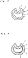
- a baseball helmet 20 as shown in Figs. 8 and 9 comprises a head 20a and a flange 20b.
- the fiber reinforcing material of the head 20a consists of an ultra-high-molecular-weight polyethylene fiber cloth layer and a felt-like nonwoven cloth layer consisting of carbon fiber and ultra-high molecular-weight polyethylene mixed with each other.
- the ultra-high-molecular-weight polyethylene fiber cloth layer and the felt-like nonwoven cloth layer alternate with each other.
- the head 20a contains fiber in the percentage of 50 by volume.
- the flange 20b is made of a nonwoven cloth layer consisting of the carbon fiber and ultra-high-molecular-weight polyethylene and contains fiber in the percentage of 20 by volume.
- the fiber reinforcing material of the head 20a and the flange 20b is preformed. That is, in case of the head 20a, the periphery of a ultra-high-molecular-weight polyethylene fiber cloth 21 as shown in Fig. 10 is cut in conformity with the surface 22a of a male die 22 of a helmet die as shown in Fig. 11 and surface-treated. A nonwoven cloth layer is laminated alternately on the surface of the ultra-high-molecular-weight polyethylene fiber cloth 21 similarly. These fiber layers are connected with each other by a binder. Thus, the fiber reinforcing materials of the head 20a are integrated with each other by alternating a desired number of both layers with each other. Both fiber reinforcing materials are laminated on each other in the same thickness.
- the flange 20b consisting of the nonwoven cloth layer is preformed similarly to the head 20a.
- an intermediate die 23 and an upper die 24 are set in position on a cavity 25 in which the fiber reinforcing materials are set.
- a resin injecting opening 24a communicating with the cavity 25 is formed in the upper die 24 and a resin discharging opening 22b is formed in the lower die 22.
- the mixing head of a resin injector is mounted on the resin injecting opening 24a.
- the die 26 is heated to 70°C and made to be vacuous.
- RIM cyclopentadiene is injected from the injecting opening 24a similarly to the tennis racket frame so that a polymerization occurs in the die 26.
- RIM cyclopentadiene is injected for eight seconds at a pressure of 10kg/cm2 and flow rate of 60cc/sec. Hardening process terminates within one minute after RIM cyclopentadiene is injected.
- a helmet as shown in Figs. 8 and 9 is obtained.
- Pressure may be applied in two stages in the above operation.
- the primary pressure is set to a low pressure a little lower than 10kg/cm2 and the secondary pressure may be set to 10kg/cm2.
- the pressure generated by the flow of resin does not cause fibers arranged in the cavity 25 from dislocating from each other.
- the above die 26 may be constructed as follows as shown in Fig. 13: That is, sheet-shaped rubber 28 is provided along a die 27 on which the fiber reinforcing material is provided and a space 29 opposite to the portion in which the fiber reinforcing material is positioned with respect to the rubber 28 communicates with a high pressure supply source not shown. After the resin is injected, the rubber 28 is pressurized to press the fiber reinforcing material against the surface of the die 27 and discharge extra resin from a resin discharge opening 27a.
- the above method increases fiber containing percentage in the reinforcing material and improves rigidity and shock resistant performance of the baseball helmet.
- woven cloth is used as the fiber reinforcing material which is preformed by placing it along the die.
- the following may be used as reinforced fiber: continuous strand mat shaped by orienting continuous fiber bundles in random directions, chopped strand mat formed by orienting fiber bundles cut to a certain length, and woven filament winding wound around a cylindrical inner ring.
- Short fiber or a chopped strand mat 30 serving as a fiber reinforcing material may be sprayed on the die 22 together with a fiber binder as a preforming method as shown in Fig. 14.
- a mat 33 is sandwiched between a male die 31 and a female die 32 and then, the dies 31 and 32 are set in position and heated as shown in Fig. 15. As a result, fiber binder melts. Then, fiber bundles are pressurized to form them in conformity with the surface configuration of the die. Thus, the fiber reinforcing material is shaped into the predetermined configuration in advance. According to this method, even though the preformed fiber reinforcing material is taken out from the die and cooled, it maintains its configuration.
- the shock resistant performance of the helmet according to the second embodiment was compared with conventional helmets.
- Tests were conducted on sample semispherical heads of 220mm in diameter under the condition as shown in Table 1. Penetration tests were conducted using a device as shown in Fig. 16. The test result is shown in Table 2.
- Tests were conducted as follows: A sample 101 was put on a sample holding tool 100 and a weight 103 having a steel striker 102 at the top end thereof is hung by a hook 104. The weight 103 was dropped to examine whether or not the striker 102 penetrated through the sample 101 and measure a maximum load and energy required in penetration therethrough. The weight of the striker 102 was 12.1kg and its speed was 3.3/sec when it collided with the helmet.
- the helmet according to the present invention is very effective for protecting human body.
- the present invention is applicable to shock resistant tools including other protecting sporting tools.
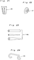
- the present invention can be preferably embodied for plastron 40 of fencing as shown in Fig. 17, face-guard 41 of fencing as shown in Fig. 18, crotch protecting tool 42 such as cup of boxing as shown in Fig. 19, football shoulder protecting tool 43 as shown in Fig. 20, soccer leg leguards as shown in Fig. 21, ear portion 45 of water polo cap as shown in Fig. 22, ice hockey face-guard, ice hockey knee pad, ice hockey elbow pad, ski arm protector or the like.
- the present invention can also be preferably embodied for a helmet for use in car, on bicycle, in construction work, for infant in play or the like.
- the present invention is also applicable to shock resistant tools, for preventing breakage, such as pipe 48 for use in bicycle frame as shown in Fig. 23, drop handle 49 of a bicycle as shown in Fig. 24, canoe (not shown) or the like.
- the present invention can be used as a face protecting mask in construction work, wall for protecting from machine tool or the like.
- Tables 3-1, 3-2, 3-3 and 3-4 show conditions in RIM molding (injection pressure, injection period of time, injection flow rate), kind of reinforcing fiber, whether or not nonwoven cloth is provided, method for arranging nonwoven cloth, kind of nonwoven cloth, distribution of reinforcing fiber and nonwoven cloth (design of fiber layer), and content percentage of fiber.
- injection pressure is set to less than as low as 20kg/cm2 and mixing and injections are carried out at a low pressure when fiber density is high.
- a region which does not require a high strength comprises a nonwoven cloth layer.
- a region which requires high strength comprises nonwoven cloth layers and reinforcing fiber layers which alternate with each other so as to accelerate the flow of resin.
- a region which requires a very high strength comprises a reinforcing fiber layer only.
- shock resistant tools according to the embodiments of the present invention are as shown in Tables 3-1, 3-2, 3-3 and 3-4 and 4 while those of conventional shock resistant tools are as follows:
- Fencing plastron was struck with bamboo swords. A shock was felt in the case of the conventional plastron, but a shock was felt in a smaller extent in the case of the plastron according to the embodiment.
- the weight of conventional fencing face-guard was 1100g while that of the embodiment was 155g. Both face-guard were struck with bamboo swords 500 times. The result is that neither the conventional face-guard nor that of the embodiment was broken. Thus, the shock resistant performance of both face-guards were similar although the face-guard of the embodiment was lighter than the conventional one.
- the weight of conventional bicycle handle made of light alloy was 290g while the bicycle handle made of light alloy of the embodiment was 210g.
- the bicycle handle of the embodiment was more operable than the conventional one because the former was lighter than the latter.
- a shock resistant tool according to the present invention such as a racket frame or a helmet contains cyclopentadiene resin, having a low melt viscosity, which is used as matrix resin, fiber can be contained in the material of the shock resistant tool at higher percentage. That is, fiber can be contained therein at a desired percentage higher than 40% while according to the conventional method, fiber is contained therein at approximately 30%. Since cyclopentadiene resin is superior in specific strength and specific rigidity, shock resistant performance of shock resistant tool according to the present invention can be outstandingly improved.
- Shock resistant performance can be improved by using, as reinforcing fiber, continuous fiber or long fiber comprising ultra-high-molecular-weight polyethylene fiber superior in shock resistant performance.
- cyclopentadiene resin has a favorable vibration damping performance as well as shock resistant performance. Therefore, a shock resistant tool, for example, a racket frame comprising cyclopentadiene resin is superior in vibration damping characteristic. That is, vibration generated by hitting a ball is transmitted to elbow in a reduced extent. Therefore, the racket frame is preferably used by a powerless player.
- reaction injection molding method Since reaction injection molding method is employed, resin injection period of time is less than 10 seconds and the hardening terminates within one minute. Therefore, molding cycle is very short and productivity is favorable.
- fibers provided in a die are not dislocated from each other and fiber can be contained in a predetermined percentage according to a region by setting the balance of flow rate, pressure, and period of time and applying a low pressure during a resin injecting operation.
- the dislocation of fibers can be effectively prevented by preforming the reinforcing fiber.
- Resin is capable of flowing smoothly by alternating the reinforcing fiber and nonwoven cloth with each other.
- the weight of a shock resistant tool can be reduced if a region in which a high strength is not required consists of nonwoven cloth. Hence, manufacturing cost is low.
Landscapes
- Engineering & Computer Science (AREA)
- Chemical & Material Sciences (AREA)
- Mechanical Engineering (AREA)
- Health & Medical Sciences (AREA)
- Materials Engineering (AREA)
- Physical Education & Sports Medicine (AREA)
- General Health & Medical Sciences (AREA)
- Composite Materials (AREA)
- Manufacturing & Machinery (AREA)
- Chemical Kinetics & Catalysis (AREA)
- Medicinal Chemistry (AREA)
- Polymers & Plastics (AREA)
- Organic Chemistry (AREA)
- Injection Moulding Of Plastics Or The Like (AREA)
- Moulding By Coating Moulds (AREA)
- Casting Or Compression Moulding Of Plastics Or The Like (AREA)
- Helmets And Other Head Coverings (AREA)
Abstract
Description
- The present invention relates to tools resistant to a mechanical shock and more particularly to tools likely to be subjected to a shock listed below.
- 1. Sporting goods such as a tennis racket frame, squash racket, badminton racket for absorbing a shock applied by a ball.
- 2. Sporting goods for absorbing a shock such as helmet; fencing plastron, fencing face-guard: crotch protecting tool; football shoulder protecting tool; ice hockey mask; ice hockey knee pad and elbow pad; soccer, squash racket, leg guards; ear protecting portion of water polo cap; horse saddle and the like.
- 3. Helmets for protecting head from accidental shock in riding car or bicycle, in construction work, and infant's play.
- 4. Bicycle frame, bicycle handle, canoe and the like for absorbing a shock and preventing breakage against a shock.
- 5. Protecting wall, against machine tool, for preventing the transmission of a shock.
- Conventionally, goods required to have a shock resistant performance are made of ABS resin, polycarbonate resin, fiber reinforced resin (FRP) formed by reinforcing thermoplastic resin with short fiber or fiber reinforced resin (FRP) formed by reinforcing thermosetting resin generally with chopped strand mat of glass. The chopped strand mat of glass may be replaced by continuous fiber, long fiber or short fiber consisting of glass fiber, carbon fiber, aramid fiber, boron fiber or ultra-high-molecular-weight polyethylene fiber. Unsaturated polyester resin is mainly used as matrix resin.
- The following methods are used to manufacture the above fiber reinforced resins formed by reinforcing thermosetting resin with chopped strand mat of glass: a half-hardened prepreg formed by impregnating fiber with resin is cut to an appropriate size and a configuration, and then, cut materials are laminated on each other in a die, then, heated under pressure so as to harden the resin; chopped strand and resin are sprayed up in a die and then hardened; reinforced fibers are laminated on a balloon-shaped die, then, the reinforcing fiber is impregnated with resin and then, hardened.
- Comparing the above materials and manufacturing methods, shock resistant tools made of only ABS resin or polycarbonate resin do not have a favorable rigidity because they do not contain a reinforcing material. Compared with long fiber or continuous fiber, fiber reinforced resin (FRP) formed by reinforcing thermoplastic resin with short fiber has also an unfavorable rigidity.
- In the case of the fiber reinforced resin (FRP) formed by reinforcing thermosetting resin with chopped strand mat of glass, shock resistant performance of molded goods can be increased by using reinforcing fiber and matrix resin favorable in shock resistant performance and increasing the content percentage of reinforcing fiber. But it is uneasy to increase fiber content and the method for manufacturing the above shock resistant goods has problems.
- That is, fiber content percentage can be increased by cutting the prepreg sheets having thermosetting resin impregnated therein to a certain configuration, laminating cut materials on a die, and heating them under pressure. But the molded goods is inferior in shock resistant performance because thermosetting resin is inferior in shock resistant performance. In addition, this method has an unfavorable production cycle and moreover, the manufacturing cost is high.
- Further, in spray-up method or bag method, glass fiber and unsaturated polyester are used in combination. These systems have a disadvantage that resin does not penetrate through fine gaps between fibers, and voids are left between filaments. The disadvantage is attributed to the high viscosity of resin. When resin is injected at a high pressure to accelerate the permeation of resin between fibers, fiber are moved and twisted by the flow of resin. Thus, resin cannot be injected at a high pressure. Therefore, fiber cannot be contained at a high percentage in a shock resistant tool. For example, fiber is contained in a helmet commercially available at approximately 30% at most.
- It is an essential object of the present invention to provide a shock resistant tool having a high fiber content percentage and a favorable shock resistant performance and a method for manufacturing the shock resistant tool.
- In accomplishing these and other objects, cyclopentadiene resin is used as matrix resin because it has a favorable shock resistant performance and increases fiber content percentage due to its low viscosity before polymerization takes place. Cyclopentadiene resin is injected into a die, by reaction injection molding method, in which reinforcing fiber is placed to obtain a shock resistant tool molded in a desired configuration.
- More specifically, a shock resistant tool comprises fiber reinforced resin molded by reaction injection molding method using at least one of reinforcing fiber of ultra-high-molecular-weight polyethylene fiber, carbon fiber, glass fiber, aramid fiber, alumina fiber, silicon carbide fiber, steel fiber, amorphous metal fiber, organic fiber and/or a combination thereof as a reinforcing material; and cyclopentadiene resin as matrix resin.
- As the reinforcing fiber as the fiber reinforced resin of the shock resistant tool, continuous fiber, long fiber or short fiber is used. When a high rigidity and a high strength are required, the continuous fiber or the long fiber is used. As an example of the reinforcing fiber, cloth fiber, filament winding, a mat in random arrangement such as continuous strand mat are preferably used.
- Preferably, fiber is contained in the shock resistant tool at more than 40% in a region in which fiber is required to be contained at the highest percentage. Reinforcing fiber is contained therein at a varied percentage depending on a region, i.e., a region to which shock is applied greatly contains the reinforcing fiber at a high percentage and a region to which shock is applied in a small extent contains the reinforcing fiber at a low percentage. Thus, the shock resistant tool is light and its production cost is reduced. For example, a shoulder protector for use in football, fiber is contained at 40% in shoulder and 20% in chest.
- Preferably, nonwoven fiber is used in combination of the reinforcing fiber as the fiber reinforcing material. It is preferable that only nonwoven fiber is used in a region in which a high strength is not required or nonwoven fiber is used at a percentage higher than the reinforcing fiber.
- It is also preferable that nonwoven cloth allowing a smooth flow of resin during a molding operation and reducing the weight of the shock resistant tool, thus reducing cost is distributed at a varied percentage according to a region. For example, the flange of a baseball helmet consists of nonwoven cloth.
- The following materials are used as the nonwoven cloth to be distributed in the outer side of the fiber reinforced resin and the surface of the inner side and/or intermediate portion thereof: glass fiber paper, carbon fiber paper, polyester nonwoven cloth, nylon nonwoven cloth, vinyl nonwoven cloth, ultra-high molecular-weight polyethylene nonwoven cloth, PPS nonwoven cloth, acrylic fiber nonwoven cloth and the like.
- Favorably, fiber density of the nonwoven cloth ranges from 1 to 35 vol% and more favorably from 2 to 20 vol% so that resin flows smoothly during a molding operation.
- Preferably, one or more kinds of fibers containing ultra-high molecular-weight polyethylene fiber is used as the reinforcing fiber.
- Shock resistant tools molded in a die by the reaction injection molding method include sporting goods such as helmet, face-guard, pad, leg guards for protecting head, face, plastron, shoulder, elbow, knee and the like; racket frame such as tennis racket frame for use in ball games; helmets for protecting head from shock in riding car or bicycle and for construction work; vehicle frame including bicycle frame and bicycle handle, canoe frame for preventing breakage against a shock; and protecting wall, against machine tool, for preventing the transmission of a shock.
- When a shock resistant tool is a racket frame, the racket frame contains ultra-high-molecular-weight polyethylene fiber at least 10 wt% in the reinforcing fiber and a resin layer including the nonwoven cloth in the inner portion, outer portion and/or intermediate portion of the fiber reinforced resin consisting of the cyclopentadiene resin reinforced with the fiber reinforcing material.
- In the method for molding shock resistant tools, preferably, reinforcing fiber and nonwoven cloth are provided in the outer side, inner side and/or the gap between reinforcing material layers. The material thus preformed is placed in a die. Then, cyclopentadiene containing polymerization catalyst and initiator of polymerization is injected into the die, and the mixture is heated at a predetermined temperature, for example, lower than 130°C so as to mold it into crosslinked resin by two-solution injection molding method (RIM).
- In the above-described method, after the reaction solution is injected, the preformed material is compressed against the surface of the die with sheet-shaped rubber shaped into the configuration in conformity with that of the die and the preformed material, and extra resin is discharged from a resin discharge opening. Thus, fiber content percentage can be increased.
- In order to preform the material, the following methods are used: molding by means of a die; spray-up of short fiber and chopped strand mat; and molding by heating and pressure application of a reinforcing material to which a binder has been attached.
- As polymerization monomer used as the cyclopentadiene resin, dicyclopentadiene, dihydrodicyclopentadiene, tricyclopentadiene, tetracyclopentadiene, cyclopentadiene-methylpentadiene copolymer are used.
- As the polymerization catalyst, halide of tungsten, molybdenum, tantalum; oxyhalide; oxide; organic ammonium salt are preferably used.
- As the polymerization starting agent, organic metal compound, mainly alkyl of metal of I through III groups of periodic table, compounds of alcohol, phenol or the like are preferably used.
- Since a polymerization reaction is started very promptly in a solution containing the catalyst and activator, hardening may occur before a sufficient amount of solution flows into the mold. Therefore, monoether and/or monoester of a glycol compound selected from alkylene glycol or polyalkylene glycol are preferably used as an activity adjusting agent.
- In injection molding in the die, the die is heated at 40 to 130°C and polymerization reaction takes place for one to five minutes.
- The material of a shock resistant tool is provided on a flexible core (internal pressure holding member) which conforms to the surface configuration of the die. Tube-shaped or bag-shaped materials such as nylon, cellophane, rubber, polyester, polyether ketone or the like is preferably used.
- As described above, a shock resistant tool according to the present invention such as a racket frame or a helmet is formed in combination of reinforcing fiber and cyclopentadiene resin superior in shock resistant performance. Since cyclopentadiene resin to be used as matrix resin has a low melt viscosity, fiber can be contained at higher than 50%. Therefore, the shock resistant performance of the tool according to the present invention can be improved as compared with conventional ones. For example, comparing a helmet according to the present invention and a conventional helmet commercially available with each other, energy required to destroy the helmet according to the present invention is approximately twice as great as that required to destroy the conventional helmet. This data is obtained as a result of tests which is described later.
- Compared with the shock resistant performance of conventional tools, in addition to shock resistant performance, vibration damping performance, chemical resistant property, and weather resistant property are improved.
- When ultra-high molecular-weight polyethylene fiber and cyclopentadiene resin are used in combination, vibration damping performance is superior, so that vibration damping ratio can be made at a high percentage, namely, higher than 0.8%. Therefore, a tennis racket frame comprising the above mixture does not apply a great force to elbow, so that it is preferably used by a powerless player. Vibration damping characteristic is preferable by providing a layer consisting of 95% of matrix resin and 5% of nonwoven cloth, namely, a layer containing much amount of resin and a small amount of nonwoven cloth. According to this distribution of ultra-high-molecular-weight polyethylene fiber and cyclopentadiene resin, the external appearance of a tool is preferable.
- Further, according to the manufacturing method, the material of the tool can be placed in a die by controlling the fiber angle, fiber amount, and fiber thickness. In addition, since the fiber reinforcing material is preformed, the molding cycle is preferable, and hence an efficient productivity can be obtained.
- These and other objects and features of the present invention will become apparent from the following description taken in conjunction with the preferred embodiments thereof with reference to the accompanying drawings, in which:
- Fig. 1 is a plan view showing a tennis racket frame according to a first embodiment of the present invention;
- Fig. 2 is a sectional view taken along a line II-II of Fig. 1;
- Fig. 3 is a sectional view showing a first modification of the first embodiment;
- Fig. 4 is a sectional view showing a second modification of the first embodiment;
- Fig. 5 is a schematic view showing strength testing method according to the first embodiment;
- Fig. 6 is a schematic view showing a testing method for examining vibration damping characteristic according to the first embodiment;
- Fig. 7 is a diagrammatic view showing vibration damping waveform obtained by a vibration damping characteristic test;
- Fig. 8 is a perspective view showing a baseball helmet according to the second embodiment;
- Fig. 9 is a perspective view showing the baseball helmet viewed from bottom portion in Fig. 8;
- Fig. 10 is a plan view showing the cloth of reinforcing fiber to be used in the second embodiment;
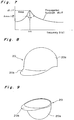
- Fig. 11 is a perspective view showing a preforming method according to the second embodiment;
- Fig. 12 is a sectional view showing a molding die according to the second embodiment;
- Fig. 13 is a sectional view showing a modified manufacturing method;
- Fig. 14 is a perspective view showing a modified preforming method;
- Fig. 15 is a perspective view showing a modified preforming method;
- Fig. 16 is a front view showing a testing device for measuring the shock absorbing performance according to the second embodiment; and
- Figs. 17 through 24 are perspective views showing a shock resistant tool according to the present invention, respectively.
- Referring now to the drawings, an embodiment of the present invention is described below.
- Fig. 1 shows a shock resistant tennis racket frame 1 according to a first embodiment of the present invention. Its length ranges from 52cm to 68cm (68cm according to the first embodiment) and its weight ranges from 230g to 400g (335g according to the first embodiment).
- The vibration damping ratio of the tennis racket frame 1 is 0.8% which is greatly improved compared with conventional tennis rackets.
- As shown in Fig. 2, the tennis racket frame 1 comprises a
core nylon tube 2 and a fiber reinforcedresin layer 3 consisting of cyclopentadiene resin containing continuous fiber, consisting of ultra-high molecular-weight polyethylene fiber and carbon fiber, formed in the periphery of thecore nylon tube 2. - The racket frame 1 is manufactured by two-solution reaction injection molding (RIM) method which will be described below.
- The
core tube 2 is made of a nylon tube in the thickness of 100µm and braided carbon fiber (article number: BC-7664-24 (20), manufactured by Toho Rayon Co., Ltd.) is arranged in the periphery of thecore nylon tube 2 so that each braided carbon fiber makes 24° with the longitudinal direction of the tennis racket frame 1 and the weight of the braided carbon fiber is 40 wt%. Braided fiber consisting of ultra-high-molecular-weight polyethylene fiber (SK-60, manufactured by Toyobo Co., Ltd.) is provided so that the braided fiber makes 24° with the longitudinal direction of the tennis racket frame 1 and the weight of the braided carbon fiber is 20 wt%. - The carbon fiber and ultra-high-molecular-weight polyethylene fiber are braided and cut so that the angle of the braided fiber makes the above-described angle, and they are preformed so that the configuration of the braided fiber conforms to that of the tennis racket frame 1. The preforming method is described later in the description of a baseball helmet according to a second embodiment. The preformed fiber reinforcing material is arranged on the periphery of the
core nylon tube 2. - After the fiber reinforcing material is set in a die and the die is heated at 60°C. Then, the pressure in the die is reduced by a vacuum pump.
- Then, dicyclopentadiene containing polymerizing catalyst and initiator of polymerization is placed in the die under pressure. That is, a desired amount of dicyclopentadiene is contained in two containers. Polymerizing catalyst is put into one container and an activator (initiator of polymerization) and an activity adjusting agent are put into the other container so as to prepare two stable reaction solutions. The reaction solutions are mixed with each other instantaneously by a mixing head of a two-solution reaction/injection molding device. The mixture is immediately injected into the die heated at 60°C under a low pressure.
- In the die, internal pressure is applied to the
core nylon tube 2 for one to five minutes to polymerize the mixture promptly. Thus, a hollow tennis racket frame as shown in Fig. 2 is obtained. - Fig. 3 shows a first modification of the tennis racket frame of the first embodiment. The tennis racket frame 1' comprises the
core nylon tube 2, a fiber reinforcedresin layer 3 consisting of cyclopentadiene resin containing continuous fiber consisting of ultra-high-molecular-weight polyethylene fiber formed in the periphery of thecore nylon tube 2, and a nonwovencloth containing layer 4 consisting of cyclopentadiene resin containing glass nonwoven cloth formed in the periphery of the fiber reinforcedresin layer 3. - The length and weight of the tennis racket frame 1' are similar to those of the first embodiment, and the vibration damping ratio thereof is 2.5% which is improved greatly compared with conventional ones.
- The method for manufacturing the tennis racket frame 1' having the nonwoven
cloth containing layer 4 is almost same as that of the first embodiment. The first modification of the first embodiment is different from the first embodiment in that the glass nonwoven cloth is provided on the surface of the ultra-high-molecular-weight polyethylene fiber provided in the periphery of thecore nylon tube 2 so that the weight percentage of the glass nonwoven cloth is approximately 5%. - Fig. 4 shows a tennis racket frame 1'' of a second modification of the tennis racket frame of the first embodiment. The tennis racket frame 1'' comprises the
nylon tuber core 2, an inner nonwovencloth containing layer 5 consisting of cyclopentadiene resin containing glass nonwoven cloth formed in the periphery of thenylon tuber core 2, a fiber reinforcedresin layer 3 consisting of cyclopentadiene resin containing continuous fiber consisting of ultra-high-molecular-weight polyethylene fiber formed in the periphery of thelayer 5, and an outer nonwovencloth containing layer 4 consisting of cyclopentadiene resin containing glass nonwoven cloth formed in the periphery of thelayer 3. The configuration and weight of the tennis racket frame 1'' according to the second modification are similar to those of the tennis racket frame 1 according to the first embodiment and the vibration damping ratio thereof is 3.5%. - The method for manufacturing the tennis racket frame 1'' according to the second modification is almost same as that of the first embodiment. The glass nonwoven cloth is formed in the periphery of the
nylon tube core 2, the continuous fiber layer consisting of ultra-high-molecular-weight polyethylene fiber is formed in the periphery thereof, and the glass nonwoven cloth is formed in the periphery thereof. The nonwoven cloth containing layer may be arranged in the middle layer, but it is preferable to arrange it on the surface of the tennis racket frame in view of the external appearance thereof. - As the reinforcing fiber, ultra-high-molecular-weight polyethylene fiber and carbon fiber are used in the first embodiment, and only ultra-high-molecular-weight polyethylene fiber is used in the first and second modifications. But the following fibers may be used in combination of ultra-high molecular-weight polyethylene fiber: glass fiber, aramid fiber, alumina fiber, silicon carbide fiber, steel fiber, amorphous metal fiber, organic fiber and/or a combination thereof. Preferably, the weight percentage of ultra-high-molecular-weight polyethylene fiber is more than 10 wt% of the reinforcing fiber material in view of vibration damping performance and shock absorbing performance.
- It is preferable that except the nonwoven resin layer, the fiber reinforcing resin layer comprising cyclopentadiene resin contains reinforcing fiber made of a material formed in combination of the above-described materials or reinforcing fiber consisting of ultra-high-molecular-weight polyethylene fiber in 20 to 80 wt%.
- The shock resistant performance, namely, the strength of the tennis racket frame of the above construction according to the present invention was compared with that of conventional tennis racket frames. The result is described below.
- As shown in Fig. 5, the tennis racket frame 1 was erected by supporting both sides thereof with a supporting
jig 15. A dead load was applied to the tennis racket frame 1 at the top end thereof by apressure applying device 16 provided above the tennis racket frame 1 so as to measure its destruction strength. - The tennis racket frames of the first modification was used to compare shock resistant performance according to the present invention with conventional example tennis racket frames made of epoxy prepreg material and in the same configuration as the racket frame of the first modification.
Embodiment 2 (four frames on average) 162kg
Conventional B (four frames on average) 160kg - It was confirmed that the strength of the tennis racket frame of the embodiment was higher than that of the conventional one.
- The vibration damping characteristic of the tennis racket frames of the present invention were compared with that of conventional tennis racket frames. Tests were conducted on the following embodiment (A) and conventional example (B).
- A: tennis racket frames according to the first embodi ment, the first modification, and the second modification (weight: 335g; length: 68cm)
- B: conventional tennis racket frames made of an epoxy prepreg material and the configurations thereof are same as those of (A)
- Experiments for examining vibration damping characteristics were made by a device as follows as shown in Fig. 6. That is, the tennis racket frame 1 was hung by a string with the head portion 1a thereof upward. An acceleration pick-
up 12 was attached to one side of the tennis racket frame 1 at approximately the center between the head portion 1a and agripping portion 1b. The other side of the tennis racket frame 1 was struck with animpact hammer 10. AnFET analyzer 17 was connected with thehammer 10 and the acceleration pick-up 12. - A vibration generated when the tennis racket frame 1 was struck with the
hammer 10 was received by the acceleration pick-up 12 and a signal was inputted to theFET analyzer 17. As a result, a graph as shown in Fig. 7 was obtained. In the graph, acceleration (α)/ force (F) is ordinate and frequency is abscissa. Vibration damping characteristics were obtained by Δω/2ωn. - Vibration damping ratios were calculated based on the graph. The result was:
First embodiment: ζ = 0.8%
First modification: ζ = 1.2%
Second modification: ζ = 1.6% - The vibration damping ratio ζ of the conventional example (B) was 0.2% to 0.3% (10 tennis racket frames were used on average.)
- A test for examining players' feeling for tennis ball hittings was conducted.
- Fifty players hit tennis balls with rackets of (A) and (B). The result is shown below.
Persons who felt that (A) was better than (B) in vibration absorbing performance - - - 46 persons
Persons who did not judge which is better - - - 4 persons
A shock resistant baseball helmet according to a second embodiment of the present invention is described below. - A
baseball helmet 20 as shown in Figs. 8 and 9 comprises ahead 20a and aflange 20b. The fiber reinforcing material of thehead 20a consists of an ultra-high-molecular-weight polyethylene fiber cloth layer and a felt-like nonwoven cloth layer consisting of carbon fiber and ultra-high molecular-weight polyethylene mixed with each other. The ultra-high-molecular-weight polyethylene fiber cloth layer and the felt-like nonwoven cloth layer alternate with each other. Thehead 20a contains fiber in the percentage of 50 by volume. Theflange 20b is made of a nonwoven cloth layer consisting of the carbon fiber and ultra-high-molecular-weight polyethylene and contains fiber in the percentage of 20 by volume. - The fiber reinforcing material of the
head 20a and theflange 20b is preformed. That is, in case of thehead 20a, the periphery of a ultra-high-molecular-weightpolyethylene fiber cloth 21 as shown in Fig. 10 is cut in conformity with thesurface 22a of amale die 22 of a helmet die as shown in Fig. 11 and surface-treated. A nonwoven cloth layer is laminated alternately on the surface of the ultra-high-molecular-weightpolyethylene fiber cloth 21 similarly. These fiber layers are connected with each other by a binder. Thus, the fiber reinforcing materials of thehead 20a are integrated with each other by alternating a desired number of both layers with each other. Both fiber reinforcing materials are laminated on each other in the same thickness. Theflange 20b consisting of the nonwoven cloth layer is preformed similarly to thehead 20a. - After the preformed fiber reinforcing materials of the
head 20a and theflange 20b are placed on the male die (lower die), anintermediate die 23 and anupper die 24 are set in position on acavity 25 in which the fiber reinforcing materials are set. Aresin injecting opening 24a communicating with thecavity 25 is formed in theupper die 24 and aresin discharging opening 22b is formed in thelower die 22. - After the dies 23 and 24 are set in position, the mixing head of a resin injector is mounted on the
resin injecting opening 24a. Then, thedie 26 is heated to 70°C and made to be vacuous. Then, RIM cyclopentadiene is injected from the injectingopening 24a similarly to the tennis racket frame so that a polymerization occurs in thedie 26. RIM cyclopentadiene is injected for eight seconds at a pressure of 10kg/cm² and flow rate of 60cc/sec. Hardening process terminates within one minute after RIM cyclopentadiene is injected. Thus, a helmet as shown in Figs. 8 and 9 is obtained. - Pressure may be applied in two stages in the above operation. The primary pressure is set to a low pressure a little lower than 10kg/cm² and the secondary pressure may be set to 10kg/cm². Thus, the pressure generated by the flow of resin does not cause fibers arranged in the
cavity 25 from dislocating from each other. - The above die 26 may be constructed as follows as shown in Fig. 13: That is, sheet-shaped
rubber 28 is provided along a die 27 on which the fiber reinforcing material is provided and aspace 29 opposite to the portion in which the fiber reinforcing material is positioned with respect to therubber 28 communicates with a high pressure supply source not shown. After the resin is injected, therubber 28 is pressurized to press the fiber reinforcing material against the surface of thedie 27 and discharge extra resin from aresin discharge opening 27a. - The above method increases fiber containing percentage in the reinforcing material and improves rigidity and shock resistant performance of the baseball helmet.
- In the second embodiment, woven cloth is used as the fiber reinforcing material which is preformed by placing it along the die. In addition to woven cloth, the following may be used as reinforced fiber: continuous strand mat shaped by orienting continuous fiber bundles in random directions, chopped strand mat formed by orienting fiber bundles cut to a certain length, and woven filament winding wound around a cylindrical inner ring.
- Short fiber or a chopped
strand mat 30 serving as a fiber reinforcing material may be sprayed on the die 22 together with a fiber binder as a preforming method as shown in Fig. 14. - When a continuous strand mat, a cloth mat or a chopped strand mat is preformed as the fiber reinforcing material, a
mat 33 is sandwiched between amale die 31 and afemale die 32 and then, the dies 31 and 32 are set in position and heated as shown in Fig. 15. As a result, fiber binder melts. Then, fiber bundles are pressurized to form them in conformity with the surface configuration of the die. Thus, the fiber reinforcing material is shaped into the predetermined configuration in advance. According to this method, even though the preformed fiber reinforcing material is taken out from the die and cooled, it maintains its configuration. - The shock resistant performance of the helmet according to the second embodiment was compared with conventional helmets.
- Tests were conducted on sample semispherical heads of 220mm in diameter under the condition as shown in Table 1. Penetration tests were conducted using a device as shown in Fig. 16. The test result is shown in Table 2.


- Tests were conducted as follows: A
sample 101 was put on asample holding tool 100 and aweight 103 having asteel striker 102 at the top end thereof is hung by ahook 104. Theweight 103 was dropped to examine whether or not thestriker 102 penetrated through thesample 101 and measure a maximum load and energy required in penetration therethrough. The weight of thestriker 102 was 12.1kg and its speed was 3.3/sec when it collided with the helmet. - Seven kinds of sample helmets were prepared. In Table 1, reference symbols (a), (b), and (c) denote conventional helmets and (d), (e), (f), and (g) denote helmets according to the present invention.
- (a) Long glass fiber is used as fiber reinforcing material. Unsaturated polyester resin is used as matrix resin.
- (b) Only ABS is used.
- (c) Glass continuous strand mat is used as reinforcing fiber. Unsaturated polyester resin is used as matrix resin.
- (d) Glass-CSM is used as reinforcing fiber. Cyclopentadiene resin is used as matrix resin.
- (e) Carbon fiber is used as reinforcing fiber. Cyclopentadiene resin is used as matrix resin.
- (f) Ultra-high-molecular-weight polyethylene fiber is used as reinforcing fiber. Cyclopentadiene resin is used as matrix resin.
- (g) Aramid resin is used as reinforcing fiber. Cyclopentadiene resin is used as matrix resin.
- As indicated in Table 2 more energy is required for the
striker 102 to penetrate through the helmets of (d) through (g) than for it to penetrate through the conventional helmets (a) through (c). That is, the former is more resistant to a shock than the conventional helmets. Much more energy is required for thestriker 102 to penetrate through a helmet comprising ultra-high-molecular-weight polyethylene fiber. Needless to say, the helmet is very resistant to a shock. Therefore, the helmet according to the present invention is very effective for protecting human body. - In addition to the tennis racket frame according to the first embodiment and the baseball helmet according to the second embodiment, the present invention is applicable to shock resistant tools including other protecting sporting tools.
- The present invention can be preferably embodied for
plastron 40 of fencing as shown in Fig. 17, face-guard 41 of fencing as shown in Fig. 18,crotch protecting tool 42 such as cup of boxing as shown in Fig. 19, footballshoulder protecting tool 43 as shown in Fig. 20, soccer leg leguards as shown in Fig. 21, ear portion 45 of water polo cap as shown in Fig. 22, ice hockey face-guard, ice hockey knee pad, ice hockey elbow pad, ski arm protector or the like. - The present invention can also be preferably embodied for a helmet for use in car, on bicycle, in construction work, for infant in play or the like.
- Further, the present invention is also applicable to shock resistant tools, for preventing breakage, such as
pipe 48 for use in bicycle frame as shown in Fig. 23, drop handle 49 of a bicycle as shown in Fig. 24, canoe (not shown) or the like. - In addition, the present invention can be used as a face protecting mask in construction work, wall for protecting from machine tool or the like.

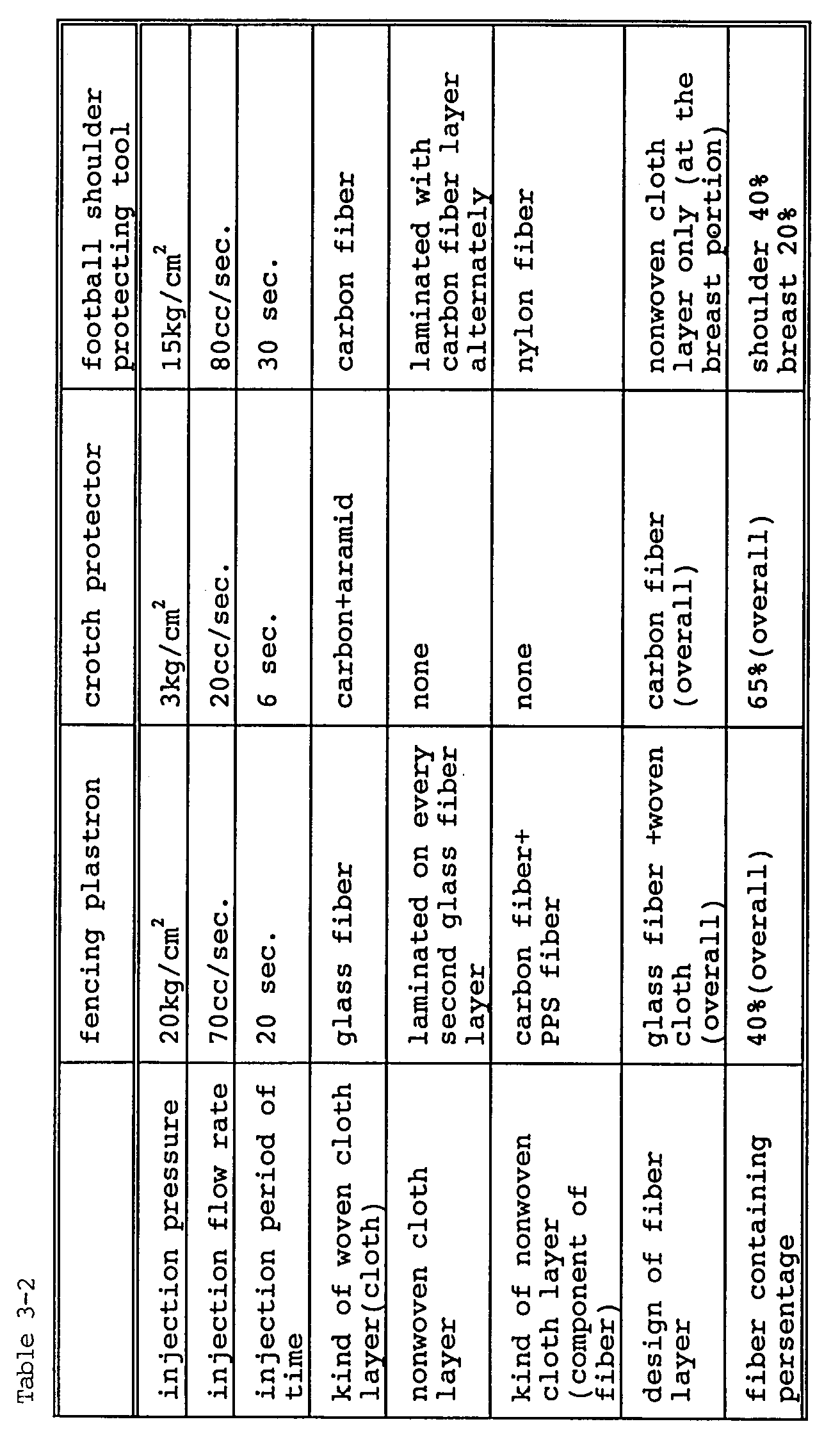
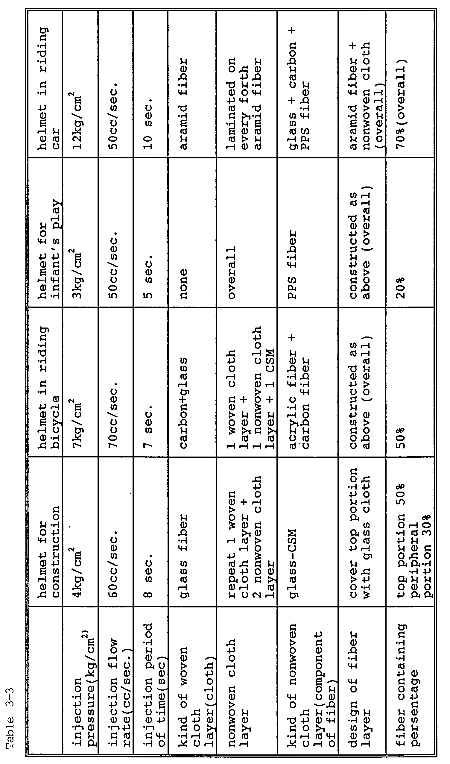

- Tables 3-1, 3-2, 3-3 and 3-4 show conditions in RIM molding (injection pressure, injection period of time, injection flow rate), kind of reinforcing fiber, whether or not nonwoven cloth is provided, method for arranging nonwoven cloth, kind of nonwoven cloth, distribution of reinforcing fiber and nonwoven cloth (design of fiber layer), and content percentage of fiber.
- As shown in Table 3-1, 3-2, 3-3 and 3-4 in the above-described embodiments, injection pressure is set to less than as low as 20kg/cm² and mixing and injections are carried out at a low pressure when fiber density is high.
- The distribution of nonwoven cloth is as follows: A region which does not require a high strength comprises a nonwoven cloth layer. A region which requires high strength comprises nonwoven cloth layers and reinforcing fiber layers which alternate with each other so as to accelerate the flow of resin. A region which requires a very high strength comprises a reinforcing fiber layer only.
- Penetration tests were conducted on the above-described shock resistant tools and conventional ones in the same configuration by the same device as shown in Fig. 16. Test results are as shown in Table 4.

- The constructions of shock resistant tools according to the embodiments of the present invention are as shown in Tables 3-1, 3-2, 3-3 and 3-4 and 4 while those of conventional shock resistant tools are as follows:
- * Plastron of fencing: prepreg formed by impregnating carbon fiber with unhardened epoxy resin was stuck to a die and then, heated and pressurized to harden it.
- * Fencing face-protecting mask: iron pipe
- * Crotch protecting tool: nylon resin (injection molding) commercially available
- * Football shoulder protecting tool: ultra-high-density polyethylene resin (injection) commercially available
- * Elbow pad and knee pad: ABS resin (injection molding) commercially available
- * Soccer leg guards: nylon resin (injection molding) commer cially available
- * Bicycle frame pipe: epoxy resin reinforced with carbon fiber (interior: urethane foam), handle made of light alloy commercially available
- Shock tests were conducted in addition to the penetration test.
- Fencing plastron was struck with bamboo swords. A shock was felt in the case of the conventional plastron, but a shock was felt in a smaller extent in the case of the plastron according to the embodiment.
- The weight of conventional fencing face-guard was 1100g while that of the embodiment was 155g. Both face-guard were struck with bamboo swords 500 times. The result is that neither the conventional face-guard nor that of the embodiment was broken. Thus, the shock resistant performance of both face-guards were similar although the face-guard of the embodiment was lighter than the conventional one.
- The weight of conventional bicycle handle made of light alloy was 290g while the bicycle handle made of light alloy of the embodiment was 210g. The bicycle handle of the embodiment was more operable than the conventional one because the former was lighter than the latter.
- As apparent from the foregoing description, a shock resistant tool according to the present invention such as a racket frame or a helmet contains cyclopentadiene resin, having a low melt viscosity, which is used as matrix resin, fiber can be contained in the material of the shock resistant tool at higher percentage. That is, fiber can be contained therein at a desired percentage higher than 40% while according to the conventional method, fiber is contained therein at approximately 30%. Since cyclopentadiene resin is superior in specific strength and specific rigidity, shock resistant performance of shock resistant tool according to the present invention can be outstandingly improved.
- Shock resistant performance can be improved by using, as reinforcing fiber, continuous fiber or long fiber comprising ultra-high-molecular-weight polyethylene fiber superior in shock resistant performance. In addition, cyclopentadiene resin has a favorable vibration damping performance as well as shock resistant performance. Therefore, a shock resistant tool, for example, a racket frame comprising cyclopentadiene resin is superior in vibration damping characteristic. That is, vibration generated by hitting a ball is transmitted to elbow in a reduced extent. Therefore, the racket frame is preferably used by a powerless player.
- Since reaction injection molding method is employed, resin injection period of time is less than 10 seconds and the hardening terminates within one minute. Therefore, molding cycle is very short and productivity is favorable.
- Further, fibers provided in a die are not dislocated from each other and fiber can be contained in a predetermined percentage according to a region by setting the balance of flow rate, pressure, and period of time and applying a low pressure during a resin injecting operation. In particular, the dislocation of fibers can be effectively prevented by preforming the reinforcing fiber.
- Resin is capable of flowing smoothly by alternating the reinforcing fiber and nonwoven cloth with each other. The weight of a shock resistant tool can be reduced if a region in which a high strength is not required consists of nonwoven cloth. Hence, manufacturing cost is low.
- Although the present invention has been fully described in connection with the preferred embodiments thereof with reference to the accompanying drawings, it is to be noted that various changes and modifications are apparent to those skilled in the art. Such changes and modifications are to be understood as included within the scope of the present invention as defined by the appended claims unless they depart therefrom.
Claims (9)
- A shock resistant tool comprising fiber reinforced resin molded by reaction injection molding method using at least one of reinforcing fiber of ultra-high-molecular-weight polyethylene fiber, carbon fiber, glass fiber, aramid fiber, alumina fiber, silicon carbide fiber, steel fiber, amorphous metal fiber, organic fiber and/or a combination thereof as a reinforcing material; and cyclopentadiene resin as matrix resin.
- A shock resistant tool as defined in claim 1, wherein said reinforcing fiber is continuous fiber or long fiber.
- A shock resistant tool as defined in claim 1, wherein fiber is contained at more than 40% in a region in which fiber is required to be contained at the highest percentage.
- A shock resistant tool as defined in claim 1, wherein nonwoven cloth is used together with said reinforcing fiber and the distribution ratio of said nonwoven cloth is high in a region which requires a high strength and low in a region which does not require a high strength.
- A shock resistant tool as defined in claim 1, wherein said tool is sporting goods such as helmet, face-guard, pad, leg guards for protecting head, face, plastron, shoulder, elbow, knee; racket frame such as tennis racket frame for use in ball games; helmets for protecting head from shock in riding car or bicycle and for construction work; vehicle frame including bicycle frame and bicycle handle, canoe frame for preventing breakage against a shock; or protecting wall against machine tool for preventing the transmission of a shock.
- A shock resistant tool as defined in claim 1, wherein said shock resistant tool is a racket frame and said racket frame contains ultra-high-molecular-weight polyethylene fiber at least 10 wt% in said reinforcing fiber and a resin layer including said nonwoven cloth in the inner portion, outer portion and/or intermediate portion of said fiber reinforced resin consisting of said cyclopentadiene resin reinforced with said fiber reinforcing material.
- A method for manufacturing a shock resistant tool comprising fiber reinforced resin molded into a desired configuration by reaction molding injection method using at least one of reinforcing fiber of ultra-high-molecular-weight polyethylene fiber, carbon fiber, glass fiber, aramid fiber, alumina fiber, silicon carbide fiber, steel fiber, amorphous metal fiber, organic fiber and/or a combination thereof as a reinforcing material; and cyclopentadiene resin as matrix resin.
- A method for manufacturing a shock resistant tool as defined in claim 7, wherein said reinforcing fiber is used continuous fiber or long fiber.
- A method for manufacturing a shock resistant tool as defined in claim 7, wherein said reinforcing material is previously preformed to the shape of the tool, the preform is placed in a die, and the matrix resin is injected, whereby said tool is made by reaction injection molding.
Applications Claiming Priority (4)
| Application Number | Priority Date | Filing Date | Title |
|---|---|---|---|
| JP205690/90 | 1990-07-31 | ||
| JP20569090 | 1990-07-31 | ||
| JP3162851A JPH089186B2 (en) | 1990-07-31 | 1991-07-03 | Impact resistant tool and method for manufacturing the impact resistant tool |
| JP162851/91 | 1991-07-03 |
Publications (2)
| Publication Number | Publication Date |
|---|---|
| EP0471237A1 true EP0471237A1 (en) | 1992-02-19 |
| EP0471237B1 EP0471237B1 (en) | 1997-02-05 |
Family
ID=26488490
Family Applications (1)
| Application Number | Title | Priority Date | Filing Date |
|---|---|---|---|
| EP91112824A Expired - Lifetime EP0471237B1 (en) | 1990-07-31 | 1991-07-30 | A method for manufacturing a shock resistant tool of fiber reinforced resin |
Country Status (4)
| Country | Link |
|---|---|
| US (1) | US5424021A (en) |
| EP (1) | EP0471237B1 (en) |
| JP (1) | JPH089186B2 (en) |
| DE (1) | DE69124554T2 (en) |
Families Citing this family (20)
| Publication number | Priority date | Publication date | Assignee | Title |
|---|---|---|---|---|
| US5503773A (en) * | 1994-09-08 | 1996-04-02 | Genesis Composites, L.C. | Method of making a composite handlebar |
| SE9703343L (en) * | 1997-09-17 | 1999-03-18 | Volvo Ab | Load-bearing vehicle structure of composite material and method of forming it |
| US6292952B1 (en) | 1998-09-25 | 2001-09-25 | Sportscope, Inc. | Insert-molded helmet |
| US6159324A (en) * | 1999-03-05 | 2000-12-12 | Sportscope | Process for manufacturing protective helmets |
| US6969478B1 (en) * | 2000-10-12 | 2005-11-29 | Lion Apparel, Inc. | Fiberglass composite firefighting helmet and method for making a fiberglass composite firefighting helmet |
| US6803005B2 (en) | 2001-11-14 | 2004-10-12 | Mjd Innovations, Llc | Method for making multi-layer, personnel-protective helmet shell |
| US6931671B2 (en) * | 2003-07-22 | 2005-08-23 | Joseph Skiba | Lightweight impact resistant helmet system |
| US8143337B1 (en) | 2005-10-18 | 2012-03-27 | The Ohio State University | Method of preparing a composite with disperse long fibers and nanoparticles |
| US7708851B2 (en) * | 2005-10-25 | 2010-05-04 | General Electric Company | Process of producing a ceramic matrix composite article and article formed thereby |
| US20080028499A1 (en) * | 2006-08-04 | 2008-02-07 | Sport Maska Inc. | Protective shell construction and method |
| DE102009020448A1 (en) * | 2009-05-08 | 2010-11-11 | Rehau Ag + Co. | High-strength injection-molded part and method for producing a highly rigid injection-molded part |
| US20130221555A1 (en) * | 2011-08-26 | 2013-08-29 | Basf Se | Process for producing moldings |
| EP3294571B1 (en) * | 2015-05-12 | 2023-07-05 | Berd L.L.C. | Spoke composed of braided fiber with hub and rim terminations |
| DE102017119535A1 (en) * | 2017-08-25 | 2019-02-28 | ABUS August Bremicker Söhne KG | Method of making a protective helmet and protective helmet made according to this method |
| EP3816211A4 (en) * | 2018-06-07 | 2022-04-13 | Rimtec Corporation | COMPOSITE AND MOLDED COMPOSITE |
| US11052587B2 (en) * | 2018-08-24 | 2021-07-06 | Easton Diamond Sports, Llc | Modular molding systems and methods for making batting helmets |
| JP7247066B2 (en) * | 2019-09-25 | 2023-03-28 | ヨネックス株式会社 | badminton racket |
| CA3160198A1 (en) * | 2019-11-12 | 2021-05-20 | Neuvokas Corporation | Method of manufacturing a composite material |
| US20210246576A1 (en) * | 2020-02-10 | 2021-08-12 | Red Bank Technologies Llc | Stretched polymers, products containing stretched polymers and their method of manufacture |
| ES3034411T3 (en) | 2020-09-06 | 2025-08-18 | Berd L L C | Hub for retaining spokes with loops |
Citations (1)
| Publication number | Priority date | Publication date | Assignee | Title |
|---|---|---|---|---|
| EP0344693A2 (en) * | 1988-06-01 | 1989-12-06 | Hercules Incorporated | Improving the physical properties of glass composite polydicyclopentadiene by heat treatment |
Family Cites Families (6)
| Publication number | Priority date | Publication date | Assignee | Title |
|---|---|---|---|---|
| US4500595A (en) * | 1982-07-22 | 1985-02-19 | Plastic Specialties And Technologies, Inc. | Stainless steel fiber-thermosplastic granules and molded articles therefrom |
| US4473616A (en) * | 1983-12-21 | 1984-09-25 | Monsanto Company | Molded articles comprising fiber reinforced styrene polymers |
| US4708969A (en) * | 1984-11-16 | 1987-11-24 | Hercules Incorporated | Cycloolefin composition and method for making high TG fiber reinforced polymeric product |
| US4849486A (en) * | 1985-07-10 | 1989-07-18 | Nippon Oil Co., Ltd. | Polyphenylene ether resin composition |
| JPS6428077A (en) * | 1988-06-24 | 1989-01-30 | Mazda Motor | Lower body structure of automobile |
| JPH0667411B2 (en) * | 1989-05-17 | 1994-08-31 | 美津濃株式会社 | Ski and method for manufacturing the same |
-
1991
- 1991-07-03 JP JP3162851A patent/JPH089186B2/en not_active Expired - Fee Related
- 1991-07-30 EP EP91112824A patent/EP0471237B1/en not_active Expired - Lifetime
- 1991-07-30 DE DE69124554T patent/DE69124554T2/en not_active Expired - Fee Related
-
1993
- 1993-09-02 US US08/115,360 patent/US5424021A/en not_active Expired - Fee Related
Patent Citations (1)
| Publication number | Priority date | Publication date | Assignee | Title |
|---|---|---|---|---|
| EP0344693A2 (en) * | 1988-06-01 | 1989-12-06 | Hercules Incorporated | Improving the physical properties of glass composite polydicyclopentadiene by heat treatment |
Non-Patent Citations (2)
| Title |
|---|
| DATABASE WPIL, no. 89-374 241 DERWENT PUBLICATIONS LTD., London, GB * |
| DATABASE WPIL, no. 91-032 865 DERWENT PUBLICATIONS LTD., London, GB * |
Also Published As
| Publication number | Publication date |
|---|---|
| JPH089186B2 (en) | 1996-01-31 |
| US5424021A (en) | 1995-06-13 |
| EP0471237B1 (en) | 1997-02-05 |
| DE69124554D1 (en) | 1997-03-20 |
| JPH04357010A (en) | 1992-12-10 |
| DE69124554T2 (en) | 1997-06-26 |
Similar Documents
| Publication | Publication Date | Title |
|---|---|---|
| US5424021A (en) | Method of making a shock resistant tool comprising a fiber reinforced cyclopentadiene resin matrix | |
| US6335100B1 (en) | Structural material and process for its production | |
| US4124670A (en) | Method of producing a composite high strength to weight structure having a shell and weight controlled cellular core | |
| US4874171A (en) | Golf club set | |
| US4212461A (en) | Composite high strength to weight structure having shell and weight controlled core | |
| US4070020A (en) | Composite high strength to weight structure with fray resistance | |
| US10226881B2 (en) | Hockey stick | |
| FI102813B (en) | Game Club | |
| US4129634A (en) | Method for preparing a composite high strength to weight structure having shell and sleeved core | |
| US6761653B1 (en) | Composite wrap bat with alternative designs | |
| US7651420B1 (en) | Injection-molded ball bat | |
| US10723047B2 (en) | Hockey stick | |
| EP0432398B1 (en) | Tennis racket frame | |
| EP0504230B1 (en) | Hockey stick | |
| US5482774A (en) | Composite prepeg and tennis rackets using the same | |
| JPS63212514A (en) | Structural material and its manufacture | |
| EP0231381A1 (en) | Structural material and process for its production | |
| CN1067388A (en) | sports bat | |
| CN1044329C (en) | racket frame | |
| JP4376419B2 (en) | Racket frame and manufacturing method thereof | |
| TW202529859A (en) | Manufacturing method and structure of composite material racket frame | |
| JPH02172480A (en) | sports protective gear | |
| JP3485712B2 (en) | Racket frame | |
| JP2667783B2 (en) | tennis racket | |
| JP3108026B2 (en) | tennis racket |
Legal Events
| Date | Code | Title | Description |
|---|---|---|---|
| PUAI | Public reference made under article 153(3) epc to a published international application that has entered the european phase |
Free format text: ORIGINAL CODE: 0009012 |
|
| 17P | Request for examination filed |
Effective date: 19910730 |
|
| AK | Designated contracting states |
Kind code of ref document: A1 Designated state(s): DE FR GB IT |
|
| 17Q | First examination report despatched |
Effective date: 19940309 |
|
| GRAG | Despatch of communication of intention to grant |
Free format text: ORIGINAL CODE: EPIDOS AGRA |
|
| GRAH | Despatch of communication of intention to grant a patent |
Free format text: ORIGINAL CODE: EPIDOS IGRA |
|
| GRAH | Despatch of communication of intention to grant a patent |
Free format text: ORIGINAL CODE: EPIDOS IGRA |
|
| GRAA | (expected) grant |
Free format text: ORIGINAL CODE: 0009210 |
|
| AK | Designated contracting states |
Kind code of ref document: B1 Designated state(s): DE FR GB IT |
|
| ITF | It: translation for a ep patent filed | ||
| REF | Corresponds to: |
Ref document number: 69124554 Country of ref document: DE Date of ref document: 19970320 |
|
| ET | Fr: translation filed | ||
| PLBE | No opposition filed within time limit |
Free format text: ORIGINAL CODE: 0009261 |
|
| STAA | Information on the status of an ep patent application or granted ep patent |
Free format text: STATUS: NO OPPOSITION FILED WITHIN TIME LIMIT |
|
| 26N | No opposition filed | ||
| PGFP | Annual fee paid to national office [announced via postgrant information from national office to epo] |
Ref country code: DE Payment date: 20010723 Year of fee payment: 11 |
|
| PGFP | Annual fee paid to national office [announced via postgrant information from national office to epo] |
Ref country code: GB Payment date: 20010725 Year of fee payment: 11 |
|
| REG | Reference to a national code |
Ref country code: GB Ref legal event code: IF02 |
|
| PG25 | Lapsed in a contracting state [announced via postgrant information from national office to epo] |
Ref country code: GB Free format text: LAPSE BECAUSE OF NON-PAYMENT OF DUE FEES Effective date: 20020730 |
|
| PG25 | Lapsed in a contracting state [announced via postgrant information from national office to epo] |
Ref country code: DE Free format text: LAPSE BECAUSE OF NON-PAYMENT OF DUE FEES Effective date: 20030201 |
|
| GBPC | Gb: european patent ceased through non-payment of renewal fee |
Effective date: 20020730 |
|
| PGFP | Annual fee paid to national office [announced via postgrant information from national office to epo] |
Ref country code: FR Payment date: 20050708 Year of fee payment: 15 |
|
| PG25 | Lapsed in a contracting state [announced via postgrant information from national office to epo] |
Ref country code: IT Free format text: LAPSE BECAUSE OF NON-PAYMENT OF DUE FEES Effective date: 20050730 |
|
| REG | Reference to a national code |
Ref country code: FR Ref legal event code: TP |
|
| REG | Reference to a national code |
Ref country code: FR Ref legal event code: ST Effective date: 20070330 |
|
| PG25 | Lapsed in a contracting state [announced via postgrant information from national office to epo] |
Ref country code: FR Free format text: LAPSE BECAUSE OF NON-PAYMENT OF DUE FEES Effective date: 20060731 |