EP0503193A2 - Sealed power clamp - Google Patents
Sealed power clamp Download PDFInfo
- Publication number
- EP0503193A2 EP0503193A2 EP91310292A EP91310292A EP0503193A2 EP 0503193 A2 EP0503193 A2 EP 0503193A2 EP 91310292 A EP91310292 A EP 91310292A EP 91310292 A EP91310292 A EP 91310292A EP 0503193 A2 EP0503193 A2 EP 0503193A2
- Authority
- EP
- European Patent Office
- Prior art keywords
- actuating member
- actuating
- disposed
- chamber
- piston
- Prior art date
- Legal status (The legal status is an assumption and is not a legal conclusion. Google has not performed a legal analysis and makes no representation as to the accuracy of the status listed.)
- Withdrawn
Links
Images


Classifications
-
- B—PERFORMING OPERATIONS; TRANSPORTING
- B25—HAND TOOLS; PORTABLE POWER-DRIVEN TOOLS; MANIPULATORS
- B25B—TOOLS OR BENCH DEVICES NOT OTHERWISE PROVIDED FOR, FOR FASTENING, CONNECTING, DISENGAGING OR HOLDING
- B25B5/00—Clamps
- B25B5/06—Arrangements for positively actuating jaws
- B25B5/061—Arrangements for positively actuating jaws with fluid drive
-
- B—PERFORMING OPERATIONS; TRANSPORTING
- B25—HAND TOOLS; PORTABLE POWER-DRIVEN TOOLS; MANIPULATORS
- B25B—TOOLS OR BENCH DEVICES NOT OTHERWISE PROVIDED FOR, FOR FASTENING, CONNECTING, DISENGAGING OR HOLDING
- B25B5/00—Clamps
- B25B5/06—Arrangements for positively actuating jaws
- B25B5/12—Arrangements for positively actuating jaws using toggle links
- B25B5/122—Arrangements for positively actuating jaws using toggle links with fluid drive
-
- B—PERFORMING OPERATIONS; TRANSPORTING
- B25—HAND TOOLS; PORTABLE POWER-DRIVEN TOOLS; MANIPULATORS
- B25B—TOOLS OR BENCH DEVICES NOT OTHERWISE PROVIDED FOR, FOR FASTENING, CONNECTING, DISENGAGING OR HOLDING
- B25B5/00—Clamps
- B25B5/16—Details, e.g. jaws, jaw attachments
- B25B5/163—Jaws or jaw attachments
Definitions
- This invention relates to clamping devices and particularly to a unique fully sealed fluid actuated offset power toggle clamp ideally suited for holding workpieces in fixture in adverse environments, such as those contaminated with weld splatter, saw chips, coolants, dust and dirt, and the like.
- Power clamps are used in industrial applications for holding workpieces of many sizes and shapes during forming and machining operations.
- Such devices typically include a pneumatically or hydraulically actuated cylinder which causes one or more arms to move through a desired range of rotational motion to push against a workpiece.
- the user may wish to actuate one arm or two arms, in some cases vertically aligned and in other cases horizontally aligned, as well as reversible, and often in the aforesaid contaminated environment.
- a further object of this invention is to provide such a power clamp which is very compact, embodying a minimum of components, and one which is easily adapted by the user for various applications.
- the power clamp of the present invention comprises a body 10 having at one end a bolted-on end cap 12 defining a sealed cylinder chamber 14 having a longitudinal axis and at the opposite end a cylindrical bore 16 concentric with said center axis, a smaller concentric bore 15 interconnecting bores 14 and 16 and provided with an elastomeric seal 17.
- Body 10 also defines an actuating chamber 18 having a circular cylindrical wall portion 20 extending for more than 180° about a transverse axis lying in a plane spaced from and disposed transversely to said longitudinal axis.
- Actuating chamber 18 intersects bore 16 and is open at each end, body 10 having generally flat parallel opposed surfaces 22 at the open ends of actuating chamber 18.
- End cap 12 is sealed to body 10 by an elastomeric seal 24, and has a central port 25 in fluid communication with threaded ports 26 and 28 to connect a supply of actuating fluid under pressure, and if desired a proximity sensor (not shown) to determine the position of the mechanism.
- a piston 30 is slidingly disposed in cylinder chamber 14 for powered movement in both directions along said longitudinal axis. Movement of piston 30 in the advance or clamping direction is caused by the supply of fluid under pressure via port 26 or 28 and port 25, and movement in the opposite or retracting direction is caused by pressurized fluid supplied through a threaded port 26 or 28 and corresponding port 36 or 38, respectively. If desired, the mused one of these latter ports may be provided with a proximity sensor (not shown) for sensing a probe 40 on piston 30, to thereby automatically determine when the piston is fully advanced. Suitable elastomeric seals 42 and 44 may be provided to increase the seal across piston 30.
- a cylindrical slider member 46 is reciprocably slidable in bore 16 and has one end bifurcated to define a slot 48.
- a piston rod 50 is rigidly connected at one end to piston 30 by means of a threaded fastener 52, and at the opposite end to the non-bifurcated end of slider member 46 by means of a threaded fastener 54.
- the inner end of connecting rod 50 may be provided with a probe 56 to cooperate with a sensor in either one of ports 26 or 28 to automatically determine when the piston is in its fully retracted position.
- a generally circular cylindrical drum-shaped actuating member 58 is rotationally disposed in actuating chamber 18 for rotational movement about said transverse axis and supported by wall 20, actuating member 58 having generally flat parallel opposite side faces 60 which are substantially flush with body surfaces 22 and a relatively wide centrally disposed first slot 62 in the peripheral surface thereof to provide clearance for slider member 46.
- Actuating member 58 also has a relatively narrow second slot 64 in the bottom of first slot 62, and a plurality of circumferentially disposed transverse through holes 66 which extend between side faces 60, holes 66 having center axes parallel to and at equal radii from said transverse axis and perferably being spaced 45° apart.
- Linkage means comprising a link 68 having one end disposed in slider member slot 48 and being pivotally connected to the slider member by means of a pin 70 disposed in a transverse hole 72 through slider member 46, pin 70 being retained in place by a spaced pair of snap rings 73 disposed in appropriate groove in hole 72.
- the opposite end of link 68 is disposed in slot 64 and is pivotally connected to actuating member 58 by means of a pin 74 disposed in a transverse hole 76 in actuator member 58, and retained in place by a spaced pair of snap rings 78 located in suitable grooves in hole 76.
- end plates 80 and 82 are disposed over and affixed by a centered double ended through bolt 84 and nuts 86 to each face 60 of actuating member 58.
- End plate 82 has a pair of diametrically opposed transverse holes 88 in the face thereof abutting actuating member 58, holes 88 being of the same diameter as and at the same radius from said transverse axis as the plurality of holes 68.
- a pin 92 is fixedly disposed (i.e., press fit) in each of said holes 88 in cover plate 82, and upon assembly the two pins are removably inserted into a diametrically opposed pair of holes 66 in actuating member 58 in order to circumferentially position cover plate 82 with respect to actuating member 58 and to insure that cover plate 82 is positively rotatably driven by actuating member 58.
- each said cover plate overlies the adjacent surface of the body to substantially seal the actuating chamber from contaminants and to permanently retain lubricant. Because bore 16 has to be formed from the left hand end of the body, as shown in Figure 3, sealing of the internal mechanism is further effected by means of a snap-in cap 90. Sealing is further enhanced by a pair of generally parallel spaced O-rings 91 between actuator member 58 and body 10.
- Rigidly affixed, or integral with, cover plate 82 is a generally radially extending clamping arm 94 arranged to be rotated between an advanced clamping position A, as shown in solid lines in Figure 2, and a retracted unclamping position R, as shown in phantom lines in Figure 2, upon actuation of said piston in both directions, respectively.
- Threaded holes 96 may be provided in arm 94 to accommodate soft pads, small fixtures, holding devices, and the like.
- any number of mounting holes 98 may be provided on body 10 in order to facilitate mounting the clamp wherever desired.
- clamping positions of arm 94 are illustrated in Figure 8 (the arm is vertical) and in Figure 9 (the arm is horizontal). These positions are easily established by removing the cover plate and repositioning pins 92 in different pairs of holes in the actuating member. Furthermore, the clamping arm can be located on the opposite side of the clamp ( Figure 10) using the other ends of holes 66 or clamping arms can be located on both sides of the clamp ( Figure 11).
- the clamp should be installed so that full clamping takes place at or near the "center” position of the toggle linkage, i.e., within 5°, and preferably short of "center". Where power is no problem, a slightly overcenter setting may to insure that there will be sufficient force to unclamp.
Landscapes
- Engineering & Computer Science (AREA)
- Mechanical Engineering (AREA)
- Jigs For Machine Tools (AREA)
- Gripping Jigs, Holding Jigs, And Positioning Jigs (AREA)
Abstract
An offset powered toggle clamp which is very compact and in which the entirety of the actuating mechanism is fully enclosed so that it is sealed from contaminants and can be permanently lubricated. The clamp also accommodates various clamping arm (94) locations and orientations for different applications.
Description
- This invention relates to clamping devices and particularly to a unique fully sealed fluid actuated offset power toggle clamp ideally suited for holding workpieces in fixture in adverse environments, such as those contaminated with weld splatter, saw chips, coolants, dust and dirt, and the like.
- Power clamps are used in industrial applications for holding workpieces of many sizes and shapes during forming and machining operations. Such devices typically include a pneumatically or hydraulically actuated cylinder which causes one or more arms to move through a desired range of rotational motion to push against a workpiece. Depending on the specific application, the user may wish to actuate one arm or two arms, in some cases vertically aligned and in other cases horizontally aligned, as well as reversible, and often in the aforesaid contaminated environment.
- In view of the above, it is an object of this invention to provide a fully sealed, permanently lubricated power clamp suited for broad application and being capable of use in even the most contaminated environments. A further object of this invention is to provide such a power clamp which is very compact, embodying a minimum of components, and one which is easily adapted by the user for various applications.
- Additional benefits and advantages of the present invention will become apparent to those skilled in the art to which this invention relates and from the subsequent description of the preferred embodiments and the appended claims, taken in conjunction with the accompanying drawings.
-
- Figure 1 is a perspective view of a power clamp according to the present invention;
- Figure 2 is a side elevational view of the front portion of the power clamp shown in Figure 1 showing the range of motion of the clamping arm;
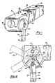
- Figure 3 is a longitudinal vertical cross-section view of the power clamp shown in Figure 1 taken generally through the center thereof and showing the mechanism in a fully advanced clamping position;
- Figure 4 is a transverse cross-sectional view taken along line 4-4 in Figure 3;
- Figure 5 is a transverse cross-sectional view taken along line 5-5 in Figure 3;
- Figure 6 is a front elevational view of the power clamp shown in Figure 1;
- Figure 7 is a fragmentary longitudinal cross-sectional view similar to Figure 3 showing the mechanism in a fully retracted position;
- Figures 8 and 9 are diagrammatic side elevational views of a power clamp in accordance with the present invention showing two additional of the many alternative positions in which the clamping arm can be mounted when in the clamping position; and
- Figures 10 and 11 are front elevational views of the clamp of the present invention showing alternative mounting positions for the clamping arm or arms.
- With reference to the drawings, the power clamp of the present invention comprises a
body 10 having at one end a bolted-onend cap 12 defining a sealedcylinder chamber 14 having a longitudinal axis and at the opposite end a cylindrical bore 16 concentric with said center axis, a smallerconcentric bore 15interconnecting bores 14 and 16 and provided with anelastomeric seal 17.Body 10 also defines anactuating chamber 18 having a circularcylindrical wall portion 20 extending for more than 180° about a transverse axis lying in a plane spaced from and disposed transversely to said longitudinal axis. Actuatingchamber 18 intersects bore 16 and is open at each end,body 10 having generally flat parallelopposed surfaces 22 at the open ends of actuatingchamber 18.End cap 12 is sealed tobody 10 by anelastomeric seal 24, and has acentral port 25 in fluid communication with threadedports - A piston 30 is slidingly disposed in
cylinder chamber 14 for powered movement in both directions along said longitudinal axis. Movement of piston 30 in the advance or clamping direction is caused by the supply of fluid under pressure viaport port 25, and movement in the opposite or retracting direction is caused by pressurized fluid supplied through a threadedport corresponding port elastomeric seals - A
cylindrical slider member 46 is reciprocably slidable in bore 16 and has one end bifurcated to define a slot 48. Apiston rod 50 is rigidly connected at one end to piston 30 by means of a threadedfastener 52, and at the opposite end to the non-bifurcated end ofslider member 46 by means of a threadedfastener 54. The inner end of connectingrod 50 may be provided with aprobe 56 to cooperate with a sensor in either one ofports - A generally circular cylindrical drum-shaped actuating
member 58 is rotationally disposed in actuatingchamber 18 for rotational movement about said transverse axis and supported bywall 20, actuatingmember 58 having generally flat parallelopposite side faces 60 which are substantially flush withbody surfaces 22 and a relatively wide centrally disposedfirst slot 62 in the peripheral surface thereof to provide clearance forslider member 46. Actuatingmember 58 also has a relatively narrowsecond slot 64 in the bottom offirst slot 62, and a plurality of circumferentially disposed transverse throughholes 66 which extend betweenside faces 60,holes 66 having center axes parallel to and at equal radii from said transverse axis and perferably being spaced 45° apart. - Linkage means comprising a
link 68 having one end disposed in slider member slot 48 and being pivotally connected to the slider member by means of apin 70 disposed in atransverse hole 72 throughslider member 46,pin 70 being retained in place by a spaced pair ofsnap rings 73 disposed in appropriate groove inhole 72. The opposite end oflink 68 is disposed inslot 64 and is pivotally connected to actuatingmember 58 by means of apin 74 disposed in atransverse hole 76 inactuator member 58, and retained in place by a spaced pair ofsnap rings 78 located in suitable grooves inhole 76. As a consequence, movement of piston 30 in one direction causes actuatingmember 58 to rotate in one direction and movement of piston 30 in the opposite direction causes actuatingmember 58 to rotate in the opposite direction. - In order to fully seal the internal mechanism of the clamp, generally
circular end plates nuts 86 to eachface 60 of actuatingmember 58.End plate 82 has a pair of diametrically opposedtransverse holes 88 in the face thereof abutting actuatingmember 58,holes 88 being of the same diameter as and at the same radius from said transverse axis as the plurality ofholes 68. Apin 92 is fixedly disposed (i.e., press fit) in each of saidholes 88 incover plate 82, and upon assembly the two pins are removably inserted into a diametrically opposed pair ofholes 66 in actuatingmember 58 in order to circumferentially positioncover plate 82 with respect to actuatingmember 58 and to insure thatcover plate 82 is positively rotatably driven by actuatingmember 58. - As can be seen, each said cover plate overlies the adjacent surface of the body to substantially seal the actuating chamber from contaminants and to permanently retain lubricant. Because bore 16 has to be formed from the left hand end of the body, as shown in Figure 3, sealing of the internal mechanism is further effected by means of a snap-in
cap 90. Sealing is further enhanced by a pair of generally parallel spaced O-rings 91 betweenactuator member 58 andbody 10. - Rigidly affixed, or integral with,
cover plate 82 is a generally radially extendingclamping arm 94 arranged to be rotated between an advanced clamping position A, as shown in solid lines in Figure 2, and a retracted unclamping position R, as shown in phantom lines in Figure 2, upon actuation of said piston in both directions, respectively. Threadedholes 96 may be provided inarm 94 to accommodate soft pads, small fixtures, holding devices, and the like. Also, any number ofmounting holes 98 may be provided onbody 10 in order to facilitate mounting the clamp wherever desired. - Alternate clamping positions of
arm 94 are illustrated in Figure 8 (the arm is vertical) and in Figure 9 (the arm is horizontal). These positions are easily established by removing the cover plate and repositioningpins 92 in different pairs of holes in the actuating member. Furthermore, the clamping arm can be located on the opposite side of the clamp (Figure 10) using the other ends ofholes 66 or clamping arms can be located on both sides of the clamp (Figure 11). - In all embodiments of the present invention the clamp should be installed so that full clamping takes place at or near the "center" position of the toggle linkage, i.e., within 5°, and preferably short of "center". Where power is no problem, a slightly overcenter setting may to insure that there will be sufficient force to unclamp.
Claims (11)
- A powered clamp, comprising:(a) a body defining a sealed cylinder chamber having a longitudinal axis, a cylindrical bore concentric with said axis, and an actuating chamber having a circular cylindrical wall portion extending for more than 180° about an axis lying in a plane spaced from and disposed transversely to said longiudinal axis, said actuating chamber intersecting said bore and being open at each end, said body having generally flat parallel opposed surfaces at the open ends of said actuating chamber;(b) a piston slidably disposed in said cylinder chamber for powered movement in both directions along said longitudinal axis;(c) a cylindrical slider member reciprocably slidable in said bore and having one end bifurcated to define a slot;(d) a piston rod interconnecting said piston and the other end of said slider member for powering the latter;(e) a generally circular cylindrical actuating member rotationally disposed in said actuating chamber for rotational movement about said transverse axis, said actuating member having generally flat parallel opposite side faces which are substantially flush with said body surface,(i) said actuating member having a relatively wide centrally disposed first slot in the peripheral surface thereof to provide clearance for said slider member,(ii) means defining a relatively narrow second slot in the bottom of said first slot,(iii) a plurality of circumferentially disposed transverse holes in one of said side faces, said holes having center axes parallel to and at equal radii from said transverse axis;(f) linkage means having one end disposed in said slider member slot and being pivotally connected to said slider member, and at the opposite end being disposed in said second slot and pivotally connected to said actuating member so that movement of said piston in one direction causes said actuating member to rotate in one direction and movement of said piston in the opposite direction causes said actuating member to rotate in the opposite direction;(g) a generally circular end plate disposed over and affixed to each side face of said actuating member, one of said end plates having a transverse hole in the face thereof abutting said actuating member, said last-mentioned hole being of the same diameter as and at the same radius from said transverse axis as said plurality of holes, each said cover plate overlying said adjacent surface of said body to substantially seal said actuating chamber;(h) a pin disposed in said hole in said cover plate and one of said plurality of holes in said actuating member in order to circumferentially position said cover plate with respect to said actuating member and to insure that said one cover plate is rotatably driven by said actuating member; and(i) a clamping arm affixed to said one of said cover plates, said arm rotating between an advanced clamping position and a retracted unclamping position upon actuating of said piston in both directions.
- A powered clamp, comprising:(a) a body having a longitudinal axis and defining an actuating chamber having a circular cylindrical wall portion extending for more than 180° about an axis lying in a plane spaced from and disposed transversely to said longiudinal axis, said actuating chamber being open at each end, said body having generally flat parallel opposed surfaces at the open ends of said actuating chamber;(b) a power means operable in two directions;(c) a generally circular cylindrical actuating member rotationally disposed in said actuating chamber for rotative movement about said transverse axis, said actuating member having generally flat parallel opposite side faces which are substantially flush with said body surface;(d) linkage means interconnecting said piston and said actuating member so that operation of said power means in one direction causes said actuating member to rotate in one direction and movement of said piston in the opposite direction causes said actuating member to rotate in the opposite direction;(e) a generally circular end plate disposed over and affixed to each side face of said actuating member, each said cover plate overlying said adjacent surface of said body to substantially seal said actuating chamber; and(f) a clamping arm affixed to said one of said cover plates, said arm rotating between an advanced clamping position and a retracted unclamping position upon actuation of said power means in both directions.
- A powered clamp as claimed in claim 2, further comprising a plurality of circumferentially disposed transverse holes in one of said side faces, said holes having centre axes parallel to and at equal radii from said transverse axis, and wherein one of said end plates has a transverse hole in the face thereof abutting said actuating member, said last-mentioned hole being of the same diameter as and at the same radius from said transverse axis a said plurality of holes.
- A powered clamp, comprising:(a) a body having a longitudinal axis and defining an actuating chamber disposed transversely to said longiudinal axis, said actuating chamber being open at each end;(b) power means operable in two directions;(c) a generally circular cylindrical actuating member rotationally disposed in said actuating chamber for rotative movement about said transverse axis, said actuating member having generally flat parallel opposite side faces which are substantially flush with the adjacent surfaces of said body;(d) linkage means interconnecting said power means and said actuating member so that actuation of said power means in one direction causes said actuating member to rotate in one direction and actuating of said power means in the opposite direction causes said actuating member to rotate in the opposite direction;(e) a generally circular end plate disposed over and affixed to each side face of said actuating member, one of said end plates having a transverse hole in the face thereof abutting said actuating member, said last-mentioned hole being of the same diameter as and at the same radius from said transverse axis as said plurality of holes, each said cover plate overlying said adjacent surface of said body to substantially seal said actuating chamber;(f) a pin disposed in said hole in said cover plate and one of said plurality of holes in said actuating member in order to circumferentially position said cover plate with respect to said actuating member and to insure that said one cover plate is rotatably driven by said actuating member; and(g) a clamping arm affixed to said one of said cover plates, said arm rotating between an advanced clamping position and a retracted unclamping position, upon actuation of said power means in both directions.
- A powered clamp as claimed in claim 1, 3 or 4, wherein said transverse holes are through holes communicating with both opposed side faces of said actuating member.
- A powered clamp as claimed in any preceding claim, wherein either of said end plates can have a clamping arm affixed thereto.
- A powered clamp as claimed in any preceding claim, wherein both of said end plates has a clamping arm affixed thereto.
- A powered clamp as claimed in any preceding claim, wherein said one of said cover plates can be mounted to said actuating member at a plurality of different angular positions by positioning said pin in different ones of said plurality of transverse holes.
- A powered clamp, comprising:(a) a body defining a sealed cylinder chamber having a longitudinal axis and an actuating chamber disposed transversely to said longiudinal axis, said actuating chamber being open at each end;(b) a piston slidably disposed in said cylinder chamber for powered movement in both directions along said longitudinal axis;(c) a cylindrical slider member reciprocably slidable in said bore and having one end bifurcated to define a slot;(d) a piston rod interconnecting said piston and the other end of said slider member for powering the latter;(e) a generally circular cylindrical actuating member rotationally disposed in said actuating chamber for rotative movement about said transverse axis,(i) said actuating member having a relatively wide centrally disposed first slot in the peripheral surface thereof to provide clearance for said slider member,(ii) means defining a relatively narrow second slot in the bottom of said first slot,(f) linkage means having one end disposed in said slider member slot and being pivotally connected to said slider member, and at the opposite end being disposed in said second slot and pivotally connected to said actuating member so that movement of said piston in one direction causes said actuating member to rotate in one direction and movement of said piston in the opposite direction causes said actuating member to rotate in the opposite direction;(g) a generally circular end plate disposed over the open ends of said actuating chamber and affixed to said actuating member; and(h) a clamping arm affixed to said one of said cover plates, said arm rotating between an advanced clamping position and a retracted unclamping position, upon actuation of said piston in both directions.
- A powered clamp as claimed in any preceding claim, wherein said linkage means incorporates a toggle link to increase clamping forces.
- A powered clamp as claimed in any preceding claim, further comprising an elastomeric seal between said body and said actuating member adjacent the ends thereof.
Applications Claiming Priority (2)
| Application Number | Priority Date | Filing Date | Title |
|---|---|---|---|
| US07/667,504 US5171001A (en) | 1987-05-27 | 1991-03-11 | Sealed power clamp |
| US667504 | 2000-09-22 |
Publications (2)
| Publication Number | Publication Date |
|---|---|
| EP0503193A2 true EP0503193A2 (en) | 1992-09-16 |
| EP0503193A3 EP0503193A3 (en) | 1993-01-13 |
Family
ID=24678488
Family Applications (1)
| Application Number | Title | Priority Date | Filing Date |
|---|---|---|---|
| EP19910310292 Withdrawn EP0503193A3 (en) | 1991-03-11 | 1991-11-06 | Sealed power clamp |
Country Status (4)
| Country | Link |
|---|---|
| US (1) | US5171001A (en) |
| EP (1) | EP0503193A3 (en) |
| JP (1) | JPH04310340A (en) |
| CA (1) | CA2055269A1 (en) |
Cited By (5)
| Publication number | Priority date | Publication date | Assignee | Title |
|---|---|---|---|---|
| EP0692343A1 (en) * | 1994-07-13 | 1996-01-17 | DE-STA-CO Metallerzeugnisse GmbH | Clamping device |
| EP0769353A1 (en) * | 1995-10-19 | 1997-04-23 | TÜNKERS MASCHINENBAU GmbH | Toggle clamp |
| EP1201369A2 (en) * | 2000-10-16 | 2002-05-02 | Delaware Capital Formation, Inc. | Power clamp mechanism |
| EP1231025A2 (en) * | 2001-02-08 | 2002-08-14 | TÜNKERS MASCHINENBAU GmbH | Toggle lever clamping device |
| EP1563955A1 (en) * | 2004-02-13 | 2005-08-17 | DE-STA-CO Metallerzeugnisse GmbH | Clamping Device |
Families Citing this family (40)
| Publication number | Priority date | Publication date | Assignee | Title |
|---|---|---|---|---|
| US5575462A (en) * | 1994-08-17 | 1996-11-19 | Blatt; John A. | Rotary clamp for a linear actuator |
| US5634629A (en) * | 1994-12-22 | 1997-06-03 | Isi Norgren Inc. | Rotary clamp having a common plane mounting arrangement |
| US6115898A (en) * | 1995-06-06 | 2000-09-12 | Btm Corporation | Force multiplying apparatus for clamping a workpiece and forming a joint therein |
| US5884903A (en) | 1995-10-30 | 1999-03-23 | Btm Corporation | Powered clamp and gauging apparatus |
| US5704600A (en) * | 1995-12-05 | 1998-01-06 | Robinson; Brian Owen | Power operated clamp assembly |
| US6105947A (en) * | 1996-08-28 | 2000-08-22 | Delaware Capital Formation, Inc. | Low profile pneumatic retractor clamp |
| US5967502A (en) * | 1996-09-04 | 1999-10-19 | Delaware Capital Formation, Inc. | Enclosed pneumatic clamp |
| DE19652468C1 (en) * | 1996-12-17 | 1998-02-26 | Sta Co Mettallerzeugnisse Gmbh | Operating gear for installation in head piece or housing of elbow lever tension device |
| JP4099729B2 (en) * | 1997-03-05 | 2008-06-11 | Smc株式会社 | Cylinder device |
| US5871250A (en) * | 1997-03-31 | 1999-02-16 | Btm Corporation | Sealed straight line gripper |
| US6200059B1 (en) | 1997-08-19 | 2001-03-13 | Btm Corporation | Tool adjustment system |
| DE29717492U1 (en) * | 1997-09-30 | 1997-11-27 | Festo AG & Co, 73734 Esslingen | Fastening device for fastening a sensor |
| US6722842B1 (en) | 1998-01-13 | 2004-04-20 | Btm Corporation | End arm manipulator |
| US6059277A (en) * | 1998-05-05 | 2000-05-09 | Btm Corporation | Retracting power clamp |
| DE19824579C1 (en) | 1998-06-02 | 1999-06-17 | Tuenkers Maschinenbau Gmbh | Bell-crank lever clamping device or piston and cylinder unit |
| US6070864A (en) * | 1998-11-03 | 2000-06-06 | Isi Norgren, Inc. | Electric power operated positioning apparatus |
| US6119843A (en) * | 1999-02-03 | 2000-09-19 | Robinson; Brian Owen | Retractable stop assembly |
| JP2001001274A (en) * | 1999-06-17 | 2001-01-09 | Smc Corp | Clamp device |
| US6502880B1 (en) | 2000-03-08 | 2003-01-07 | Btm Corporation | Pin part locator |
| US6412845B1 (en) | 2000-07-07 | 2002-07-02 | Btm Corporation | Sealed gripper |
| US6416045B1 (en) | 2000-07-25 | 2002-07-09 | Norgren Automotive, Inc. | Rotary clamp having predetermined adjustable clamping angles |
| US6488273B2 (en) * | 2001-04-20 | 2002-12-03 | Btm Corporation | Powered pivot unit |
| US6616133B1 (en) | 2001-07-18 | 2003-09-09 | Norgren Automotive, Inc. | Linear actuator having an adjustable piston rod |
| US6666489B2 (en) * | 2001-08-23 | 2003-12-23 | Btm Corporation | Sealed gripper apparatus |
| US6908077B2 (en) * | 2002-09-26 | 2005-06-21 | Btm Corporation | Clamp with swinging and linear motion |
| US6755406B2 (en) * | 2002-10-30 | 2004-06-29 | Delaware Capital Formation, Inc. | Enclosed power clamp |
| US6877730B2 (en) * | 2003-05-29 | 2005-04-12 | Btm Corporation | Powered clamp |
| US7815176B2 (en) | 2003-09-11 | 2010-10-19 | Phd, Inc. | Lock mechanism for pin clamp assembly |
| US7182326B2 (en) | 2004-04-02 | 2007-02-27 | Phd, Inc. | Pin clamp |
| US7516948B2 (en) | 2004-04-02 | 2009-04-14 | Phd, Inc. | Pin clamp accessories |
| US7448607B2 (en) | 2004-12-15 | 2008-11-11 | Phd, Inc. | Pin clamp assembly |
| US7370856B2 (en) * | 2005-10-04 | 2008-05-13 | Btm Corporation | Rotating head pin clamp |
| DE102006022950A1 (en) * | 2006-05-17 | 2007-11-22 | De-Sta-Co Europe Gmbh | Clamping device for fixing workpieces |
| CA2690801C (en) | 2007-06-19 | 2015-05-26 | Bruce D. Mcintosh | Pin clamp assembly |
| US8376336B2 (en) | 2008-06-18 | 2013-02-19 | Phd, Inc. | Strip off pin clamp |
| FR2952320B1 (en) * | 2009-11-12 | 2011-12-16 | Sta Co France De | DEVICE FOR GRIPPING A CLAMPING OBJECT COMPRISING A MAIN BODY, ARTICULATED ROD HOLDERS, AND ACTUATING MEANS |
| US8459626B2 (en) | 2010-05-28 | 2013-06-11 | Btm Corporation | Pin clamp |
| DE102011018988A1 (en) * | 2011-04-28 | 2012-10-31 | De-Sta-Co Europe Gmbh | actuator |
| DE102012100186A1 (en) * | 2012-01-11 | 2013-07-11 | De-Sta-Co Europe Gmbh | swivel device |
| JP6410342B2 (en) * | 2014-06-04 | 2018-10-24 | パスカルエンジニアリング株式会社 | Fluid pressure cylinder and clamping device |
Citations (7)
| Publication number | Priority date | Publication date | Assignee | Title |
|---|---|---|---|---|
| GB1413751A (en) * | 1972-05-09 | 1975-11-12 | Tuenkers Gmbh | Clamping devices |
| FR2296494A1 (en) * | 1974-12-31 | 1976-07-30 | Carel Fouche Languepin | Pneumatic clamping arrangement for industrial purposes - has double acting cylinder for actuating a rotating clamping lever |
| FR2340798A1 (en) * | 1976-02-13 | 1977-09-09 | Polymatic Sa | IRREVERSIBLE CLAMP HEAD WITH FLOATING HITCH AND QUICK DISASSEMBLY |
| US4494739A (en) * | 1983-03-04 | 1985-01-22 | State Die & Engineering, Inc. | Power operated rotatable clamping assembly |
| FR2588494A1 (en) * | 1985-10-11 | 1987-04-17 | Renault Automation | Device for clamping parts |
| EP0235571A2 (en) * | 1986-01-30 | 1987-09-09 | DE-STA-CO Metallerzeugnisse GmbH | Clamping device |
| EP0293755A2 (en) * | 1987-05-30 | 1988-12-07 | DE-STA-CO Metallerzeugnisse GmbH | Clamping device |
Family Cites Families (19)
| Publication number | Priority date | Publication date | Assignee | Title |
|---|---|---|---|---|
| US1667616A (en) * | 1927-02-24 | 1928-04-24 | Harry J Wright | Transmission stand |
| US1736171A (en) * | 1928-03-22 | 1929-11-19 | Pullman Car & Mfg Corp | Air clamp |
| US2381999A (en) * | 1943-11-11 | 1945-08-14 | Lapointe Machine Tool Co | Work holding fixture for broaching machines |
| US3058214A (en) * | 1961-12-12 | 1962-10-16 | Mekler Dan | Hydraulically operatable hand tool |
| US3273878A (en) * | 1964-03-11 | 1966-09-20 | Leland F Blatt | Power clamp |
| US3371923A (en) * | 1965-08-17 | 1968-03-05 | Leland F. Blatt | Mount for cylinder operated power clamp |
| JPS4632453Y1 (en) * | 1967-02-10 | 1971-11-09 | ||
| JPS4724800Y1 (en) * | 1967-02-13 | 1972-08-04 | ||
| US3545050A (en) * | 1969-01-30 | 1970-12-08 | I S I Mfg Inc | Power clamp with pull-back action |
| US3618931A (en) * | 1970-01-19 | 1971-11-09 | Leland F Blatt | Cam wedge power clamp |
| US3702185A (en) * | 1970-12-11 | 1972-11-07 | Leland F Blatt | Cylinder operated power clamp |
| DE2813694C2 (en) * | 1978-03-30 | 1981-09-17 | Tünkers Maschinenbau GmbH, 4030 Ratingen | Pressurized medium-actuated toggle lever clamping device with a double acting clamping cylinder in which a differential piston is guided in a longitudinally displaceable manner |
| DE3130942A1 (en) * | 1981-08-05 | 1983-04-28 | Tünkers Maschinenbau GmbH, 4030 Ratingen | PRESSURE-OPERATIONAL TOGLE LEVER TENSIONER WITH ELASTIC SPRING JOINT AND DETACHABLE ARM |
| US4496138A (en) * | 1982-03-26 | 1985-01-29 | Blatt Leland F | Power operated clamp |
| US4396183A (en) * | 1982-05-10 | 1983-08-02 | Lymburner Robert K | Power actuated clamp |
| FR2555926B1 (en) * | 1983-12-02 | 1986-09-12 | Franche Comte Alsace Etudes Te | PNEUMATIC TENSIONER WITH KNEE SUPPORT |
| JPH0610891Y2 (en) * | 1988-04-06 | 1994-03-23 | 株式会社資生堂 | Cosmetic container |
| US4905973B1 (en) * | 1989-01-11 | 1994-07-05 | John A Blatt | Power operated clamp with externally mounted adjustable clamp arm |
| JPH0414011U (en) * | 1990-05-29 | 1992-02-04 |
-
1991
- 1991-03-11 US US07/667,504 patent/US5171001A/en not_active Expired - Lifetime
- 1991-11-06 EP EP19910310292 patent/EP0503193A3/en not_active Withdrawn
- 1991-11-12 CA CA002055269A patent/CA2055269A1/en not_active Abandoned
-
1992
- 1992-01-13 JP JP4023207A patent/JPH04310340A/en active Pending
Patent Citations (7)
| Publication number | Priority date | Publication date | Assignee | Title |
|---|---|---|---|---|
| GB1413751A (en) * | 1972-05-09 | 1975-11-12 | Tuenkers Gmbh | Clamping devices |
| FR2296494A1 (en) * | 1974-12-31 | 1976-07-30 | Carel Fouche Languepin | Pneumatic clamping arrangement for industrial purposes - has double acting cylinder for actuating a rotating clamping lever |
| FR2340798A1 (en) * | 1976-02-13 | 1977-09-09 | Polymatic Sa | IRREVERSIBLE CLAMP HEAD WITH FLOATING HITCH AND QUICK DISASSEMBLY |
| US4494739A (en) * | 1983-03-04 | 1985-01-22 | State Die & Engineering, Inc. | Power operated rotatable clamping assembly |
| FR2588494A1 (en) * | 1985-10-11 | 1987-04-17 | Renault Automation | Device for clamping parts |
| EP0235571A2 (en) * | 1986-01-30 | 1987-09-09 | DE-STA-CO Metallerzeugnisse GmbH | Clamping device |
| EP0293755A2 (en) * | 1987-05-30 | 1988-12-07 | DE-STA-CO Metallerzeugnisse GmbH | Clamping device |
Cited By (7)
| Publication number | Priority date | Publication date | Assignee | Title |
|---|---|---|---|---|
| EP0692343A1 (en) * | 1994-07-13 | 1996-01-17 | DE-STA-CO Metallerzeugnisse GmbH | Clamping device |
| EP0769353A1 (en) * | 1995-10-19 | 1997-04-23 | TÜNKERS MASCHINENBAU GmbH | Toggle clamp |
| EP1201369A2 (en) * | 2000-10-16 | 2002-05-02 | Delaware Capital Formation, Inc. | Power clamp mechanism |
| EP1201369A3 (en) * | 2000-10-16 | 2003-12-17 | Delaware Capital Formation, Inc. | Power clamp mechanism |
| EP1231025A2 (en) * | 2001-02-08 | 2002-08-14 | TÜNKERS MASCHINENBAU GmbH | Toggle lever clamping device |
| EP1231025A3 (en) * | 2001-02-08 | 2004-01-02 | TÜNKERS MASCHINENBAU GmbH | Toggle lever clamping device |
| EP1563955A1 (en) * | 2004-02-13 | 2005-08-17 | DE-STA-CO Metallerzeugnisse GmbH | Clamping Device |
Also Published As
| Publication number | Publication date |
|---|---|
| CA2055269A1 (en) | 1992-09-12 |
| EP0503193A3 (en) | 1993-01-13 |
| US5171001A (en) | 1992-12-15 |
| JPH04310340A (en) | 1992-11-02 |
Similar Documents
| Publication | Publication Date | Title |
|---|---|---|
| EP0503193A2 (en) | Sealed power clamp | |
| US6059277A (en) | Retracting power clamp | |
| CA1233322A (en) | Automatic centering and gripper apparatus | |
| US5118088A (en) | Power clamp | |
| JP2002339916A (en) | Device having adjustable stroke and engaging workpiece | |
| US6105947A (en) | Low profile pneumatic retractor clamp | |
| US5160124A (en) | Clamping apparatus for work | |
| US6902159B2 (en) | Sealed pin locating and clamping apparatus | |
| US5634629A (en) | Rotary clamp having a common plane mounting arrangement | |
| US6877730B2 (en) | Powered clamp | |
| US20050035516A1 (en) | Sealed pin locator clamp | |
| US5967502A (en) | Enclosed pneumatic clamp | |
| US5713118A (en) | Apparatus for positioning an element on a surface | |
| US6412845B1 (en) | Sealed gripper | |
| US4575062A (en) | Coupling construction and clamp therefor | |
| US5791032A (en) | Robotic turret tool | |
| JP2002195211A (en) | Fluid equipment and shot pin device | |
| US5380117A (en) | Apparatus for the detachable coupling of gripping devices or corresponding tools on robot arms | |
| EP0937545B1 (en) | Enclosed pneumatic clamp | |
| ATE95456T1 (en) | MILLING DEVICE FOR DEBURRING. | |
| JP3644882B2 (en) | Clamping device | |
| US5110146A (en) | Collet clamping and releasing yoke apparatus | |
| CN210305820U (en) | Automatic hold type gas-liquid chuck tightly | |
| EP0937538A1 (en) | Low profile pneumatic retractor clamp | |
| US4381858A (en) | Fluid operated workholder |
Legal Events
| Date | Code | Title | Description |
|---|---|---|---|
| PUAI | Public reference made under article 153(3) epc to a published international application that has entered the european phase |
Free format text: ORIGINAL CODE: 0009012 |
|
| AK | Designated contracting states |
Kind code of ref document: A2 Designated state(s): DE FR GB IT SE |
|
| PUAL | Search report despatched |
Free format text: ORIGINAL CODE: 0009013 |
|
| AK | Designated contracting states |
Kind code of ref document: A3 Designated state(s): DE FR GB IT SE |
|
| 17P | Request for examination filed |
Effective date: 19930405 |
|
| STAA | Information on the status of an ep patent application or granted ep patent |
Free format text: STATUS: THE APPLICATION HAS BEEN WITHDRAWN |
|
| 18W | Application withdrawn |
Withdrawal date: 19931026 |