EP0502681B1 - Adaptives System zum Messen eines breitbandigen Signal-Rauschverhältnisses eines Übertragungskanals - Google Patents
Adaptives System zum Messen eines breitbandigen Signal-Rauschverhältnisses eines Übertragungskanals Download PDFInfo
- Publication number
- EP0502681B1 EP0502681B1 EP92301777A EP92301777A EP0502681B1 EP 0502681 B1 EP0502681 B1 EP 0502681B1 EP 92301777 A EP92301777 A EP 92301777A EP 92301777 A EP92301777 A EP 92301777A EP 0502681 B1 EP0502681 B1 EP 0502681B1
- Authority
- EP
- European Patent Office
- Prior art keywords
- signal
- sample
- channel
- block
- value
- Prior art date
- Legal status (The legal status is an assumption and is not a legal conclusion. Google has not performed a legal analysis and makes no representation as to the accuracy of the status listed.)
- Expired - Lifetime
Links
Images





Classifications
-
- H—ELECTRICITY
- H04—ELECTRIC COMMUNICATION TECHNIQUE
- H04B—TRANSMISSION
- H04B14/00—Transmission systems not characterised by the medium used for transmission
- H04B14/02—Transmission systems not characterised by the medium used for transmission characterised by the use of pulse modulation
- H04B14/06—Transmission systems not characterised by the medium used for transmission characterised by the use of pulse modulation using differential modulation, e.g. delta modulation
- H04B14/066—Transmission systems not characterised by the medium used for transmission characterised by the use of pulse modulation using differential modulation, e.g. delta modulation using differential modulation with several bits [NDPCM]
- H04B14/068—Transmission systems not characterised by the medium used for transmission characterised by the use of pulse modulation using differential modulation, e.g. delta modulation using differential modulation with several bits [NDPCM] with adaptive feedback
Definitions
- ADPCM Adaptive Differential Pulse Code Modulation
- PCM Pulse Code Modulation
- An ADPCM system does this by quantizing (compressing) an eight-bit signal sample into, for example, a four-bit sample.
- quantizing noise A by-product of The ADPCM quantizing process is so-called quantizing noise.
- the level of quantizing noise that is generated is typically minimal when an ADPCM is processing speech signals.
- the level of quantizing noise may be significant, such as when an ADPCM is processing, for example, voiceband data signals transmitted by modem equipment.
- a significant level of quantizing noise occurs because voiceband data transmissions are random, wideband signals, which undermine the capability of the ADPCM quantizing process to effectively predict and adapt to such signals.
- the twenty-one discrete tones are combined with a predetermined phase relationship and then transmitted over a target transmission channel.
- a receiver at the opposite end of the channel filters out the noise signal introduced by the transmission channel by performing a Fast Fourier Transform on the signals that it receives to remove the energy power contained in the appropriate frequency bins.
- the resulting SNR value of the received signal should then indicate whether the channel contains one or more ADPCMs.
- the SNR value obtained using twenty-one tones is susceptible to corruption by so-called intermodulation products falling within the frequency bins that contribute to the signal power level. Accordingly, the twenty-one tone measurement has to be performed a number of times to obtain an average SNR value, which, hopefully, represents an accurate SNR value for the channel that is being measured.
- Communications path 200 represents herein an end-to-end connection, which may be established by either a private or public network and which may contain one or more ADPCMs, such as ADPCM 205.
- path 200 may also contain various types of switching and transmission equipment (not shown) operable for establishing path 200. As is also well-known, such equipment may change, to a certain degree, the shape of signals passing through path 200, and subject such signals to a certain amount of propagation delay.
- ADPCM equipment in a transmission path as well as the degree of channel shaping imposed by the path may be readily determined by transmitter 100 and receiver 300 when they are arranged in accordance with the principles of the invention.
- transmitter 100 comprises Digital Signal Processor (DSP) 110, which may be, for example, the WEDSP16A available from AT&T.
- DSP Digital Signal Processor
- the program which implements the invention in DSP 110 is stored in ROM 105, in which ROM 105 may be, for example, the model 27C512 electrically programmable ROM available from Texas Instruments.
- Also stored in ROM 105 is a series of digital samples of a signal (tone) having a predetermined frequency, for example, a frequency of 1004 Hz.
- DSP 110 operating under the control of the program stored in ROM 105 sequentially unloads the samples from ROM 105 and passes them, one at a time, to Digital-to-Analog Converter (DAC) 115 operating at a sampling clock rate of, for example, 16,000 Hz.
- DAC 115 in a conventional manner, converts each digital sample of a signal that it receives from DSP 110 into an analog equivalent and outputs the result to communications path 200 (hereinafter "channel" 200) for transmission to receiver 300.
- channel 200 communications path 200
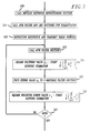
- transmitter 100 may be appreciated with reference to FIGs. 2 and 3, in which FIG. 2 shows in how chart form the program which implements the invention in transmitter 100 and in wich FIG. 3 illustrates the signals that transmitter 100 outputs to channel 200.
- FIG. 2 shows in how chart form the program which implements the invention in transmitter 100 and in wich FIG. 3 illustrates the signals that transmitter 100 outputs to channel 200.
- the program of FIG. 2 is invoked at block 400.
- the program initializes a software counter and then proceeds to block 401.
- the program unloads from ROM 105 a digital sample of the 1004 Hz signal (tone) and passes the sample to DAC 115 for transmission to channel 200 in an analog form, as illustrated by signal "a" of FIG. 2.
- the program then proceeds to block 402 where it increments the counter and then compares the contents of the counter with a predetermined value indicative of rime period, or interval, TO.
- interval TO may be, for example 1.0 seconds. If value of the contents of the counter equals the predetermined value then the program proceeds to block 403. Otherwise, the program returns to block 401 where it causes the next sample of the 1004 Hz tone to be transmitted to channel 200, in the manner dicussed above.
- the program initializes the software counter and, during interval T1, continues to transmit the 1004 Hz tone signal "c". In doing so, however, the program reverses the phase of the tone signal, as represented at point "b" of FIG. 3, in which the phase reversal may be, for example, 180 degrees. The reason for the phase reversal will be made apparent below in connection with a discussion of the operation of receiver 300.
- the program at block 404 increments the software counter and then compares the value of the counter with the aforementioned predetermined number to determine if it has transmitted the tone signal for T1 seconds. If the value of the software counter equals the predetermined number then the program proceeds to block 405. Otherwise, the program returns to block 403 where it unloads from ROM 405 the next digital sample of the 1004 Hz tone, and then compliments the digital value to reverse the phase of the analog equivalent that is transmitted to channel 200, as represented by signal "c".
- the program initializes the aforementioned software counter and enters a software program which implements a conventional noise generator.
- the noise generator program generates a digital sample of a pseudorandom noise signal (represented by signal "d" of FIG. 3) and passes the sample to a low pass filter, which is implemented at block 406 of the program.
- the low-pass filter of block 406 is designed in a conventional manner to pass the energy of noise signals having a frequency within a predetermined frequency range of, for example, a sample of 0 Hz to 4000 Hz.
- a filtered sample is then passed to DAC 115 which transmits the analog equivalent thereof to channel 200.
- interval T2 may be, for example, 2.0 seconds. If the contents of the software counter is indicative of 2.0 seconds, then the program exits via block 408. Otherwise, the program returns to block 405 where it generates the next sample of the pseudorandom noise signal for transmission to channel 200.
- receiver 300 comprises a conventional Analog-to-Digital Converter (ADC) 305 for converting analog signals received via channel 200 into respective digital samples, in which ADC 305 operates at sampling clock rate of, for example, 16,000 Hz.
- ADC 305 operates at sampling clock rate of, for example, 16,000 Hz.
- DSP 310 which operates under the control of a program stored in ROM 315.
- ROM 315 may be, for example, the same model as ROM 105.
- DSP 310 which may be, for example, the same model as DSP 110, stores in sequential memory locations of RAM memory 320 the digital samples that are received via bus 306.
- T2 FIG. 2
- DSP 310 processes the stored samples to determine the SNR value of channel 200 with respect to the 1004 Hz tone and with respect to the pseudorandom noise signal, as will be explained below.
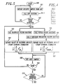
- FIGs. 5 through 8 which should be arranged as shown in FIG. 4 and which show in flow chart form the program that implements the invention in receiver 300.
- the program is entered at block 500 where it proceeds to block 501.
- the program at block 501 reads from bus 306 (FIG. 1) a digital sample, stores the sample in memory and then proceeds to block 501. 1.
- the program enters a conventional bandpass filter (BPF) routine which implements a bandpass filter centered at 1004Hz to remove from the received sample energy contributed by frequencies other than 1004Hz.
- BPF bandpass filter
- the filtered sample is then passed to block 502 which determines if the received sample is indicative of the presence of the 1004 Hz tone.
- the program at block 502 uses a conventional "zero crossing" technique to make that determination. That is, the program at block 502 "looks" for a sign change between adjacent samples and if such a change occurs between the seventh and eighth ones of such samples, then the last incoming signal sample is taken to represent a zero crossing. When the program detects a predetermined number of such zero crossings, e.g., fifty such crossings, then the program considers the incoming signal to be a 1004 Hz signal. Thereafter, the program enters a number of different software routines to process each succeeding sample of the 1004 Hz signal that is received via ADC 305 and then stored in memory.
- block 503 One such software routine is represented by block 503 and 504, in which block 503 enters the aforementioned conventional bandpass filter centered at 1004 Hz.
- the filtered sample is then passed to block 504, which implements a power function by squaring the value of the filtered sample and adding the result to a running summation (accumulation) of such results (the equation defining the latter power function is shown in block 504).
- Another, but similar, software routine is represented by blocks 505 through 507, in which block 505 implements a conventional notch filter centered at 1004 Hz to remove from the received sample energy that is contributed by the 1004 Hz signal, thereby resulting in a filtered sample indicative of noise.
- Each such filtered noise sample is passed to block 506, which weights the noise sample in accordance with a predefined C-message weighting function. (C-message weighting is discussed in the text entitled Transmission Systems for Communications, fourth, edition, Published by Bell Telephone laboratories.
- the weighted noise sample is then passed to block 507, which also implements a power function by squaring the value of the weighted noise sample and adding the result to a running summation of such results. (The equation defining the latter power function is shown in block 507.)
- the final results determined at blocks 504 and 507 will be used to determine the SNR value for channel 200 with respect to the 1004 Hz signal.
- the program obtains the next signal sample that ADC 305 presents to DSP 310 and then proceeds to block 509.
- the program checks to see if it has processed N (e.g., 8900) samples of the 1004 Hz tone signal that is being received by ADC 305. If the program finds that is not the case, then it returns to the "yes" leg out of block 502 to process the current sample in the manner discussed above. Otherwise, the program proceeds to block 510 where it enters a well-known software process that is designed to detect the aforementioned 1004 Hz phase reversal. Receiver 300 uses the phase reversal to synchronize an associated noise generation software routine (discussed below) with the noise samples that are transmitted by transmitter 100.
- N e.g. 8900
- the process at block 510 relies on the fact that during intervals T0 and T1 (FIG. 3) the 1004 Hz tone contributes most of the energy that is contained in the signal that is being received by ADC 305. However, at the phase reversal, most of the signal energy is momentarily distributed across the band, i.e., from 0 to 4KHz.
- block 510 To detect the reversal, block 510, like the processes performed at blocks 503 and 505, passes the received sample through a bandpass filter and also through a notch filter both centered at 1004 Hz. The absolute values of the output of the bandpass and notch filters are then passed through respective low-pass filters to "smooth out" the absolute values. The ouptuts of the low-pass filters are then summed with the result obtained by the notch filter. The result of the summation will be positive for signals occurring before the reversal and negative for signals occurring at the reversal.
- block 510 returns to block 508 to obtain the next sample that ADC 305 presents to DSP 310 and then determines if the current sample represents a phase reversal. Block 510 continues in that manner uni the result of the aforementioned summation is negative, at which point, block 510 proceeds to block 511, where it synchronizes receiver 300 with the noise samples supplied by transmitter 100.
- the program at block 511 counts the number of samples that DSP 310 receives from ADC 305 following the detection of the sample representing the phase reversal. When the number reaches a predetermined value, for example, a value of 8000 represented as M in FIG. 3, then the program proceeds to block 512.
- a predetermined value for example, a value of 8000 represented as M in FIG. 3, then the program proceeds to block 512.
- receiver 100 waits a predetermined period of time, for example, a time represented by M2 samples as shown in FIG. 3, before it stores in a RAM 320 (FIG. 3) receive table samples of the noise signal that is received at ADC 305 and stores in a RAM 320 reference table samples of a reference noise signal that receiver 300 generates.
- a predetermined period of time for example, a time represented by M2 samples as shown in FIG. 3, before it stores in a RAM 320 (FIG. 3) receive table samples of the noise signal that is received at ADC 305 and stores in a RAM 320 reference table samples of a reference noise signal that receiver 300 generates.
- the program at block 512 increments a counter and then proceeds to Block 513.
- the program enters a software routine which generates a reference sample of the incoming noise signal, in which the software routine is identical to the noise generator routine contained in transmitter 100.
- the program then enters the aforementioned low-pass filter routine to filter out frequency components having frequencies above 4.0 KHz.
- the program then proceeds to block 514, where it returns to block 512 if it finds that the value of the count begun at block 512 is not greater than the value of M2. Otherwise, the program proceeds to block 515 where it stores the current reference noise sample and the current noise sample received via ADC 305 in the RAM 320 reference and receive tables, respectively.
- the program begins to count the number of those samples that it is storing in RAM 320.
- the program then proceeds to block 516.
- the program checks the value of the count begun at block 515 to determine if it has generated a sufficient number of reference noise samples and has received a corresponding number of noise samples. The program does this by comparing the value of the count less the value of M3, in which the value of M3 may be, for example, 8900. Accordingly, the program proceeds to block 517 when it finds that it has stored in RAM 320 a desired number of those samples.
- the program has stored in sequential locations of RAM 320 tables 8900 samples of filtered, locally generated reference noise samples and 8900 samples of the received signal, in which the former samples should be correlated in time with the latter samples.
- the program enters a conventional Adaptive Finite Impulse Response (AFIR) filter routine which implements an AFIR filter having a predetermined number of filter taps, for example, two hundred taps, to process the samples stored in the RAM 320 reference and receive tables.
- AFIR Adaptive Finite Impulse Response
- the AFIR filter routine operating in conjunction with a conventional Least Means Squares (LMS) coefficient update routine entered at block 518 adapts to the impulse response of the transmission path, i.e., channel 200.
- LMS Least Means Squares
- the basic structure of an AFIR filter typically comprises a chain of delay stages (for example register circuits) for storing digital samples of a signal.
- a series of RAM memory locations internal to DSP 310 are used to implement the delay stages.
- each tap of the AFIR filter requires a number, e.g., three, DSP 310 internal RAM locations. One such location is used to store the filter input samples and the remaining locations are used for storing the respective tap coefficient value.
- 600 DSP 310 RAM memory locations are used to implement an AFIR having 200 taps (registers). To begin with, the digital sample stored at the first location of the reference table is retrieved and stored in the first of the two hundred memory locations.
- the value contained in each of the two hundred memory location is then multipled by a respective tap coefficient (C k ) stored in the DSP 310 TAP coefficient table and the result of each such multiplication is then summed to generate a digitally filtered version of the stored samples.
- the difference between the value of the digitally filtered sample and the value of the first sample stored in the receive table is then calculated to generate an error value e i .
- the AFIR filter routine at block 517 then shifts each sample down the chain by one memory location to the next memory location to prepare the first memory location for receipt of the next sample stored in the RAM 320 reference table.
- the AFIR routine then passes to the LMS routine at block 518 the resulting error value e1.
- the LMS routine changes (calculates) the values of the tap coefficients commensurate with the error value that it receives, and does so to minimize the error between the output ⁇ i of the AFIR filter and the corresponding receive sample.
- the updated values for the tap coefficients are then stored in respective locations of the coefficient table.
- C k+1 represents the value of the k th +1 tap coefficient vector, after being updated by the k th tap coefficient vector, C k , with the update term where represents the coefficient vector at iteration k with C ik equal to the value of the i th coefficient at iteration k, and represents the input vector at iteration k with x k-i equal to the i th input sample at iteration k, and e k is equal to the k th error sample;
- ⁇ is a constant, having a value of, for example, 0.00195.
- 8800 of the samples contained in the reference and receive tables are sequentially processed by the routines represented by blocks 517 and 518 in order to converge on the impulse response of channel 200. That is, at the end of the adaptation process the magnitudes of a group of tap coefficients stored in sequential locations of the coefficient table should closely approximate the sought-after response.
- the program at block 519 determines in a conventional manner whether 8800 of such samples have been processed. If not, then the program returns to block 517 where it reenters the AFIR filter routine.
- the AFIR filter routine supplies to the first one of the aforementioned two hundred RAM memory locations forming the delay stages of the AFIR filter the sample value stored in the next location of the reference table.
- the AFIR filter and LMS routines then proceed in the manner described above. If, on the other hand, the program finds that the latter routines have processed 8800 samples, then it proceeds to block 520.
- the program enters an "Impulse Response Repositioning" software routine that deals with any possible inaccuracy in the detection of the aforementioned phase reversal that is performed at block 510 and the limitation of using an AFIR filter having a finite length, i.e., a length of 200 taps.
- the routine entered at block 520 generates a pointer offset value that, when used in conjunction with the AMR and LMS routines, has the effect of repositioning the impulse response determined above so that the available dispersion coverage may be used efficiently.
- the program does this by scanning the filter coefficient file to locate the tap coefficient having the largest magnitude.
- the largest of such tap coefficients usually identifies the beginning of the impulse response of a so-called well-behaved connection. Once the largest coefficient is located, then its position in the file relative to a reference point of zero associated with the position of the first coefficient in the file is noted. Using the noted information, the program then generates an offset value that, when used in conjunction with the aforementioned software routines, repositions (moves) the impulse response either forward or backwards to some optimum location in the AFIR filter. In an illustrative embodiment of the invention, such an optimum location may be, for example, a location relative to the location at which the thirtieth tap is stored in the coefficient table. Thus, a repositioning, or offset, value is calculated by subtracting from the relative location of the largest coefficient the optimal location of the impulse response in the AFIR filter.
- the program proceeds to block 521 where it "recalculates" the aforementioned response by reentering blocks 517 through 519 in the order shown in the FIG. In doing so, the values of the tap coefficients in the coefficient table are initialized to zero and the offset value is used as an offset into the receive table.
- the AFIR routine operating in conjunction with the LMS routine has processed 8800 samples contained in the reference table and corresponding samples contained in the receive table, then the program proceeds to block 522.
- Blocks 523 through 527 represent a loop which the programs enters 8800 times to once again filter 8800 samples contained in the reference table. In this instance, however, the 8800 samples are filtered using the tap coefficients that the LMS routine calculated during its last entry at block 521.
- the AFIR filter after adapting to the impulse response of channel 200, generates an output sample, ⁇ i , that is indicative of the signal energy contained within the received signal samples. That is, the AFIR filter output, ⁇ i , is an estimate of the received signal and therefore can be subtracted from the composite received signal leaving only the noise component, e i , introduced by channel 200 and ADPCM 205.
- the program enters the AFIR routine which filters, in the manner discussed above, the first sample contained in the transmit reference table.
- the program performs a power function by squaring the value of the filtered result, ⁇ i , and starts a running summation of such values as defined by the equation shown in block 524.
- the program passes to the C-message filter routine the corresponding error value e i that the AMR routine calculates. The weighted error value e i that the C-message filter routine generates is then squared at block 526.
- the program at block 526 performs a power function using the weighted error value e i as defined by the equation shown in block 526.
- the program determines if 8800 samples have been filtered. If not, the program returns to block 523 to filter the next samples in the receive and reference tables and processes the filtered results thereof via blocks 524 through 526. If, on the other hand, the program finds that 8800 of such samples have been so filtered, then it proceeds to block 528.
- the program calculates and output to a terminal (not shown) via bus 312 (FIG 1) the SNR value of the channel 200 response to the pseudoramdom noise signal.
- the program calculates the SNR value by dividing the final value of the summation determined at block 524 by the final value of the summation determined at block 526, as defined by the equation shown in block 528.
- the program at block 529 calculates and output to the aforementioned terminal the SNR value of the channel 200 response to the aforementioned single tone ( 1004 Hz signal).
- the program calculates the latter SNR value by dividing the final value of the summation determined at block 504 by the final value of the summation determined at block 507, as defined by the equation shown in block 529.
- the latter SNR value is calculated and outputted since it provides a user with an indication of the transmission quality of channel 200. What this means is that if the latter SNR value is small, then the transmission quality of channel 200 may be poor, thereby making the former SNR value calculated at block 528 questionable.
- the AFIR filter coefficients are used to determine the frequency response and group delay of channel 200 as shown in the equations below.
- the output of a discrete linear system denoted as y(n) is equal to the input x(n) convolved with the system impulse response h(n), which may be mathematically stated as follows:
- FFT Fast Fourier Transform
- H(k) FFT [h(n)].
- the program determines the channel 200 group delay. This is accomplished by using the 512 frequency points obtained in block 530.
- Each of the 512 frequency points that are output from block 530 contains a real component and imaginary component which is consistent with the Fast Fourier Transform.
- the real and imaginary components are representative of the phase response of the system, in particular channel 200, at the 512 frequency points through the following equation, where ⁇ (k) is equal to the phase of the system at the k th FFT point, Real H(k) is equal to the real component of the k th FFT point, and imaginary H(k) is equal to the imaginary component of the k th FFT point.
- n th order approximation to the derivative above to determine the group delay.
- the present invention uses a first order approximmation to the above derivative which is given by, where ⁇ equals the difference in frequency between adjacent FFT points and is a constant.
- FIG. 9 there is shown one possible ROM 315 layout for the storage of the vinous software routines which implement the invention and a supervisory program which enters those routines in the manner illustrated in FIGS. 5-7.
- FIG. 10 shows one possible RAM 320 layout for the storage of the various digital samples, tap coefficient table and various SNR calculations discussed above in connection with FIGS. 5-8.
Landscapes
- Engineering & Computer Science (AREA)
- Computer Networks & Wireless Communication (AREA)
- Signal Processing (AREA)
- Filters That Use Time-Delay Elements (AREA)
- Digital Transmission Methods That Use Modulated Carrier Waves (AREA)
- Noise Elimination (AREA)
Claims (10)
- Anordnung zur Messung des Signal-Rauschverhältnisses eines Kommunikationskanals (200) miteiner Einrichtung (100) zur Erzeugung eines auf eine vorbestimmte Bandbreite begrenzten Pseudozufall-Rauschsignals und Übertragen dieses Signals an den Kanal (200) undeine Einrichtung (300) zur Abtastung des in seiner Bandbreite begrenzten Signal mit einer vorbestimmten Rate nach Übertragung über den Kanal,gekennzeichnet durcheine Einrichtung zur Erzeugung eines gefilterten Ansprechens ŷi für jeden Abtastwert des in seiner Bandbreite begrenzten Signals zur Bestimmung des Energiepegels im Abtastwert und zur Berechnung eines Fehlerwertes ei zwischen jedem gefilterten Ansprechen ŷi und einem zugeordneten Empfangsabtastwert des in seiner Bandbreite begrenzten Signals, undeine Einrichtung zur Berechnung des Signal-Rauschverhältnisses des Kanals als Funktion jedes gefilterten Ansprechens ŷi und jedes Fehlersignals ei.
- Anordnung nach Anspruch 1, dadurch gekennzeichnet, daß die Einrichtung zur Erzeugung des in seiner Bandbreite begrenzten Signals eine Einrichtung enthält, die für eine vorbestimmte Dauer vor Erzeugung des in seiner Bandbreite begrenzten Signals ein Signal einer vorbestimmten Frequenz an den Kanal liefert, derart, daß die Phase des Signals vorbestimmter Frequenz nach Ablauf eines vorbestimmten Abschnitts der Dauer umgekehrt wird.
- Anordnung nach Anspruch 1, dadurch gekennzeichnet, daß die Abtasteinrichtung eine Einrichtung zur Feststellung der Phasenumkehr enthält, um das Ende der Dauer zu bestimmen und auf diese Weise die Abtasteinrichtung mit der Übertragung des in seiner Bandbreite begrenzten Pseudozufall-Signals über den Kanal zu synchronisieren.
- Anordnung nach Anspruch 2, dadurch gekennzeichnet, daß die Abtasteinrichtung eine Einrichtung zur Abtastung des Signals vorbestimmter Frequenz und zur Zuführung des Abtastwertes an eine erste und eine zweite Filtereinrichtung enthält, um einen ersten Abtastwert und einen zweiten, bewerteten Abtastwert der Abtastung des Signals vorbestimmter Frequenz zu erzeugen, wobei die erste Filtereinrichtung die Abtastfrequenzen ausfiltert, die nicht die vorbestimmte Frequenz haben, und die zweite Filtereinrichtung die vorbestimmte Frequenz des Abtastwertes ausfiltert und dann eine bewertete Version des Filterergebnisses erzeugt, ferner eine Einrichtung zur Berechnung einer ersten Leistungssummierung, die den Wert jedes ersten, gefilterten Abtastwertes umfaßt, und einer zweiten Leistungssummierung, die den Wert jedes zweiten, gefilterten Abtastwertes umfaßt, und eine Einrichtung zur Erzeugung eines Signal-Rauschverhältnisses des Kanals mit Bezug auf das Signal vorbestimmter Frequenz als Funktion der ersten und der zweiten Leistungsfunktionen.
- Anordnung nach Anspruch 1, dadurch gekennzeichnet, daß die Abtasteinrichtung eine Einrichtung enthält, die den Abtastwert des in seiner Bandbreite begrenzten Signals bei dessen Erzeugung in einer entsprechenden ersten Tabelle sequentieller Speicherstellen eines Speichers ablegt, wobei die Anordnung ferner eine Einrichtung aufweist, die unter Ansprechen auf die Erzeugung des Abtastwertes des in seiner Bandbreite begrenzten Signals einen Bezugsabtastwert dieses Signals erzeugt, derart, daß der Bezugsabtastwert zeitlich mit einem zugeordneten Abtastwert des übertragenen, in seiner Bandbreite begrenzten Signals korreliert ist, und den Bezugsabtastwert bei seiner Erzeugung in einer entsprechenden zweiten Tabelle sequentieller Speicherstellen des Speichers ablegt.
- Anordnung nach Anspruch 5, dadurch gekennzeichnet, daß die Einrichtung zur Erzeugung des Filteransprechens ein adaptives Filter mit endlichem Impulsansprechen ist, das eine vorbestimmte Anzahl von Anzapfkoeffizienten besitzt.
- Anordnung nach Anspruch 6, dadurch gekennzeichnet, daß die Anordnung ferner eine Einrichtung zur Änderung des Wertes der Koeffizienten als Funktion des Wertes jedes Fehlers ei aufweist, so daß das adaptive Filter mit endlichem Impulsansprechen auf das Impulsansprechen des Kanals konvergieren kann.
- Anordnung nach Anspruch 7, dadurch gekennzeichnet, daß die Einrichtung zur Erzeugung des Filteransprechens ferner aufweist:eine Einrichtung, die unter Ansprechen darauf, daß das adaptive Filter mit endlichem Impulsansprechen eine vorbestimmte Anzahl der Abtastwerte des in seiner Bandbreite begrenzten Signals gefiltert hat, einen Offset-Wert als Funktion der Position des Anzapfkoeffizienten mit dem größten Wert im adaptiven Filter erzeugt,eine Einrichtung zur erneuten Filterung der in der zweiten Tabellen gespeicherten Abtastwerte und, unter Ansprechen auf jedes Filteransprechen ŷi, zur Neuberechnung des Fehlerwertes ei unter Verwendung eines entsprechenden, in der zweiten Tabelle gespeicherten Bezugsabtastwertes, wobei der erste Empfangsabtastwert, der an einer ersten Speicherstelle der ersten Tabelle abgelegt ist, um den Offset-Wert versetzt ist, eine Einrichtung, die kurz vor der erneuten Filterung die Werte der Anzapfkoeffizienten zu Anfang auf vorbestimmte Werte einstellt und unter Ansprechen auf jeden neuen Wert des Fehlers ei die Werte der Anzapfkoeffizienten so einstellt, daß das adaptive Filter mit endlichem Impulsansprechen erneut auf das Impulsansprechen konvergieren kann, undeine Einrichtung, die unter Ansprechen auf die erneute Filterung der vorbestimmten Anzahl der in der zweiten Tabelle enthaltenen Abtastwerte und unter Verwendung der letzten Werte der Anzapfkoeffizienten, die als Ergebnis der erneuten Filterung berechnet worden sind, das adaptive Filter veranlaßt, unter Verwendung der letzten Werte der Anzapfkoeffizienten diese Abtastwerte erneut zu filtern, wobei das Signal-Rauschverhältnis des Kanals mit Bezug auf das in seiner Bandbreite begrenzte Signal dann als Funktion jedes Filteransprechens ŷi berechnet wird, das als Ergebnis der letztgenannten, erneuten Filterung erzeugt worden ist.
- Anordnung nach Anspruch 8, dadurch gekennzeichnet, daß die Einrichtung zur Erzeugung des Filteransprechens ferner eine Einrichtung zur Erzeugung der Formung des in seiner Bandbreite begrenzten Signals durch den Kanal als Funktion der letzten Werte der Anzapfkoeffizienten.
- Anordnung nach Anspruch 8, dadurch gekennzeichnet, daß die Einrichtung zur Erzeugung des Filteransprechens ferner eine Einrichtung aufweist, die die durch den Kanal dem in seiner Bandbreite begrenzten Signal mitgeteilte Gruppenverzögerung bestimmt.
Applications Claiming Priority (2)
| Application Number | Priority Date | Filing Date | Title |
|---|---|---|---|
| US664908 | 1991-03-05 | ||
| US07/664,908 US5166954A (en) | 1991-03-05 | 1991-03-05 | Adaptive system for measuring the broadband signal-to-noise ratio of a transmission channel |
Publications (2)
| Publication Number | Publication Date |
|---|---|
| EP0502681A1 EP0502681A1 (de) | 1992-09-09 |
| EP0502681B1 true EP0502681B1 (de) | 1996-02-28 |
Family
ID=24667946
Family Applications (1)
| Application Number | Title | Priority Date | Filing Date |
|---|---|---|---|
| EP92301777A Expired - Lifetime EP0502681B1 (de) | 1991-03-05 | 1992-03-02 | Adaptives System zum Messen eines breitbandigen Signal-Rauschverhältnisses eines Übertragungskanals |
Country Status (3)
| Country | Link |
|---|---|
| US (1) | US5166954A (de) |
| EP (1) | EP0502681B1 (de) |
| DE (1) | DE69208489T2 (de) |
Families Citing this family (14)
| Publication number | Priority date | Publication date | Assignee | Title |
|---|---|---|---|---|
| JPH05211670A (ja) * | 1992-01-14 | 1993-08-20 | Nec Corp | 搬送波電力対雑音電力比検出回路 |
| US5363311A (en) * | 1992-09-04 | 1994-11-08 | Hughes Aircraft Company | Data compression system using response waveform discrimination |
| US5465287A (en) * | 1994-01-13 | 1995-11-07 | Teledata Communication Ltd. | Subscriber line impedance measurement device and method |
| US5526410A (en) * | 1995-01-12 | 1996-06-11 | Texas Instruments Incorporated | Method and system for determination of signal/noise ratio of telephone transmission line used for facsimile transmission |
| US6002762A (en) * | 1996-09-30 | 1999-12-14 | At&T Corp | Method and apparatus for making nonintrusive noise and speech level measurements on voice calls |
| US6041076A (en) * | 1997-12-02 | 2000-03-21 | Wavetek Corporation | Digitally modulated CATV power measurement using undersampling |
| US6111936A (en) * | 1998-01-28 | 2000-08-29 | Paradyne Corporation | Method and apparatus for automatically detecting and measuring distortion in a DSL system |
| US6618453B1 (en) * | 1999-08-20 | 2003-09-09 | Qualcomm Inc. | Estimating interference in a communication system |
| US6442495B1 (en) * | 1999-08-25 | 2002-08-27 | Southwest Research Institute | Average signal to noise ratio estimator |
| US6553098B1 (en) * | 2000-04-11 | 2003-04-22 | Verizon Laboratories Inc. | Apparatus and method for assessing leakage from cable networks |
| US7245638B2 (en) * | 2000-07-21 | 2007-07-17 | Broadcom Corporation | Methods and systems for DSP-based receivers |
| US7239680B2 (en) * | 2002-07-17 | 2007-07-03 | Broadcom Corporation | Methods for performing channel diagnostics |
| US7190718B2 (en) * | 2002-07-17 | 2007-03-13 | Broadcom Corporation | Method and apparatus for determining a receiver sampling phase for use in diagnosing a channel |
| CN110333401B (zh) * | 2019-07-16 | 2020-09-11 | 西安电子科技大学 | 高精度定噪变信方式的载噪比标定方法 |
Family Cites Families (9)
| Publication number | Priority date | Publication date | Assignee | Title |
|---|---|---|---|---|
| US4028622A (en) * | 1976-06-28 | 1977-06-07 | Bell Telephone Laboratories, Incorporated | Selective intermodulation distortion measurement |
| GB1588367A (en) * | 1977-10-18 | 1981-04-23 | Parker B D | Apparatus for selecting one of a plurality of receivers receiving a signal from a single common source |
| DE2803608C2 (de) * | 1978-01-27 | 1985-04-18 | Wandel & Goltermann Gmbh & Co, 7412 Eningen | Vierpolmeßverfahren und Schaltungsanordnung zu dessen Durchführung |
| US4417337A (en) * | 1981-06-29 | 1983-11-22 | Bell Telephone Laboratories, Incorporated, | Adaptive multitone transmission parameter test arrangement |
| US4519084A (en) * | 1982-09-29 | 1985-05-21 | At&T Bell Laboratories | Matched filter for combating multipath fading |
| US4633411A (en) * | 1982-12-27 | 1986-12-30 | Rockwell International Corporation | Link quality analyzer |
| US4539709A (en) * | 1984-03-05 | 1985-09-03 | Rockwell International Corporation | Measurement of oscillator spillover noise in a single sideband system |
| US4768203A (en) * | 1987-09-18 | 1988-08-30 | Bell Communications Research, Inc. | Signal-to-noise ratio testing in adaptive differential pulse code modulation |
| CA1272529A (en) * | 1987-12-31 | 1990-08-07 | Northern Telecom Limited | Apparatus and method for noise reduction in a digital line receiver |
-
1991
- 1991-03-05 US US07/664,908 patent/US5166954A/en not_active Expired - Lifetime
-
1992
- 1992-03-02 EP EP92301777A patent/EP0502681B1/de not_active Expired - Lifetime
- 1992-03-02 DE DE69208489T patent/DE69208489T2/de not_active Expired - Fee Related
Also Published As
| Publication number | Publication date |
|---|---|
| DE69208489D1 (de) | 1996-04-04 |
| US5166954A (en) | 1992-11-24 |
| EP0502681A1 (de) | 1992-09-09 |
| DE69208489T2 (de) | 1996-09-26 |
Similar Documents
| Publication | Publication Date | Title |
|---|---|---|
| US5166954A (en) | Adaptive system for measuring the broadband signal-to-noise ratio of a transmission channel | |
| CA2275662C (en) | Double talk and echo path change detection in a telephony system | |
| KR100683289B1 (ko) | 전송회선의 루프 길이 및 브리지형 탭 길이를 결정하기위한 시스템 및 방법과 정보 저장매체 | |
| EP0736235B1 (de) | Verfahren zur bestimmung der echolage in einem echokompensator | |
| EP0632601B1 (de) | Echokompensator | |
| EP0137508B1 (de) | Verfahren und Vorrichtung für die digitale Kompensation des in Verbindungen mit zeitvariablen Charakteristiken erzeugten Echos | |
| US4352182A (en) | Method of and device for testing the quality of digital speech-transmission equipment | |
| JP3945590B2 (ja) | 通信チャネル試験方法及び通信システム | |
| JP4104663B2 (ja) | エコー回路遅延の推定 | |
| US4633411A (en) | Link quality analyzer | |
| US20020126803A1 (en) | Line probe signal and method of use | |
| EP0557829A2 (de) | Verfahren und Anordnung zur adaptiven digitalen Löschung des in Fernsprechverbindungen mit zeitvarianten Eigenschaften erzeugten Echos | |
| JPS6364093B2 (de) | ||
| US4829566A (en) | Apparatus for detecting and discriminating phase jumps in a periodic signal and its application to a telephone tone signal with phase inversions | |
| WO2001005053A1 (en) | Fast line echo cancellation | |
| CN1813418B (zh) | 稀疏回声对消器 | |
| US5034911A (en) | Signal parameterizer | |
| CN100571225C (zh) | 适用于均衡的时间延迟的估计 | |
| US6999526B2 (en) | Method for simple signal, tone and phase change detection | |
| KR100386485B1 (ko) | 개선된음을갖는전송시스템 | |
| US6486975B1 (en) | Method and device for recognizing tones and sequences thereof | |
| RU2147791C1 (ru) | Дуплексный модем | |
| Beard et al. | A Discrete Fourier Transform based Digital DTMF Detection Algorithm | |
| DENENBERG | GGGGS LLLSS LLLL GGG TECHNICAL JOURNAL | |
| DENENBERG | THE BELL SYSTEM TECHNICAL JOURNAL |
Legal Events
| Date | Code | Title | Description |
|---|---|---|---|
| PUAI | Public reference made under article 153(3) epc to a published international application that has entered the european phase |
Free format text: ORIGINAL CODE: 0009012 |
|
| AK | Designated contracting states |
Kind code of ref document: A1 Designated state(s): DE GB IT SE |
|
| 17P | Request for examination filed |
Effective date: 19930225 |
|
| RAP3 | Party data changed (applicant data changed or rights of an application transferred) |
Owner name: AT&T CORP. |
|
| 17Q | First examination report despatched |
Effective date: 19950606 |
|
| GRAA | (expected) grant |
Free format text: ORIGINAL CODE: 0009210 |
|
| AK | Designated contracting states |
Kind code of ref document: B1 Designated state(s): DE GB IT SE |
|
| REF | Corresponds to: |
Ref document number: 69208489 Country of ref document: DE Date of ref document: 19960404 |
|
| ITF | It: translation for a ep patent filed | ||
| PLBE | No opposition filed within time limit |
Free format text: ORIGINAL CODE: 0009261 |
|
| 26N | No opposition filed | ||
| REG | Reference to a national code |
Ref country code: GB Ref legal event code: IF02 |
|
| PGFP | Annual fee paid to national office [announced via postgrant information from national office to epo] |
Ref country code: IT Payment date: 20060331 Year of fee payment: 15 |
|
| PGFP | Annual fee paid to national office [announced via postgrant information from national office to epo] |
Ref country code: DE Payment date: 20070222 Year of fee payment: 16 |
|
| PGFP | Annual fee paid to national office [announced via postgrant information from national office to epo] |
Ref country code: GB Payment date: 20070228 Year of fee payment: 16 |
|
| PGFP | Annual fee paid to national office [announced via postgrant information from national office to epo] |
Ref country code: SE Payment date: 20070307 Year of fee payment: 16 |
|
| EUG | Se: european patent has lapsed | ||
| GBPC | Gb: european patent ceased through non-payment of renewal fee |
Effective date: 20080302 |
|
| PG25 | Lapsed in a contracting state [announced via postgrant information from national office to epo] |
Ref country code: DE Free format text: LAPSE BECAUSE OF NON-PAYMENT OF DUE FEES Effective date: 20081001 Ref country code: SE Free format text: LAPSE BECAUSE OF NON-PAYMENT OF DUE FEES Effective date: 20080303 |
|
| PG25 | Lapsed in a contracting state [announced via postgrant information from national office to epo] |
Ref country code: GB Free format text: LAPSE BECAUSE OF NON-PAYMENT OF DUE FEES Effective date: 20080302 |
|
| PG25 | Lapsed in a contracting state [announced via postgrant information from national office to epo] |
Ref country code: IT Free format text: LAPSE BECAUSE OF NON-PAYMENT OF DUE FEES Effective date: 20070302 |