EP0502664B1 - Lagenselektiver, verstärkter Katheter und Verfaren für die Herstellung des verstärkten Katheters - Google Patents
Lagenselektiver, verstärkter Katheter und Verfaren für die Herstellung des verstärkten Katheters Download PDFInfo
- Publication number
- EP0502664B1 EP0502664B1 EP92301712A EP92301712A EP0502664B1 EP 0502664 B1 EP0502664 B1 EP 0502664B1 EP 92301712 A EP92301712 A EP 92301712A EP 92301712 A EP92301712 A EP 92301712A EP 0502664 B1 EP0502664 B1 EP 0502664B1
- Authority
- EP
- European Patent Office
- Prior art keywords
- catheter
- lumen
- recited
- inner sleeve
- reinforcing
- Prior art date
- Legal status (The legal status is an assumption and is not a legal conclusion. Google has not performed a legal analysis and makes no representation as to the accuracy of the status listed.)
- Expired - Lifetime
Links
Images


Classifications
-
- A—HUMAN NECESSITIES
- A61—MEDICAL OR VETERINARY SCIENCE; HYGIENE
- A61M—DEVICES FOR INTRODUCING MEDIA INTO, OR ONTO, THE BODY; DEVICES FOR TRANSDUCING BODY MEDIA OR FOR TAKING MEDIA FROM THE BODY; DEVICES FOR PRODUCING OR ENDING SLEEP OR STUPOR
- A61M25/00—Catheters; Hollow probes
- A61M25/0009—Making of catheters or other medical or surgical tubes
- A61M25/0012—Making of catheters or other medical or surgical tubes with embedded structures, e.g. coils, braids, meshes, strands or radiopaque coils
-
- A—HUMAN NECESSITIES
- A61—MEDICAL OR VETERINARY SCIENCE; HYGIENE
- A61M—DEVICES FOR INTRODUCING MEDIA INTO, OR ONTO, THE BODY; DEVICES FOR TRANSDUCING BODY MEDIA OR FOR TAKING MEDIA FROM THE BODY; DEVICES FOR PRODUCING OR ENDING SLEEP OR STUPOR
- A61M25/00—Catheters; Hollow probes
- A61M25/0043—Catheters; Hollow probes characterised by structural features
- A61M25/005—Catheters; Hollow probes characterised by structural features with embedded materials for reinforcement, e.g. wires, coils, braids
- A61M25/0052—Localized reinforcement, e.g. where only a specific part of the catheter is reinforced, for rapid exchange guidewire port
Definitions
- the present invention relates to methods and apparatus for the site-selective reinforcement for a catheter which is subjected to potentially damaging stresses due to body movement.
- the present invention relates to a method and apparatus for the reinforcement of the portion of a soft, medical grade, silicone rubber catheter which, whether by inadvertence or design, becomes disposed in the compressed area between the clavicle and first rib of a patient when the catheter is installed in the subclavian vein.
- the axillary vein becomes the subclavian vein, it travels in a very narrow triangular space bounded by the clavicle and first rib anteriorly and the anterior scalene muscle posteriorly.
- Catheters inserted using the percutaneous subclavian route pass medial to the subclavian vein in an extremely narrow space bounded by the costo-clavicular ligament in the angle between the first rib and clavicle anteriorly and the subclavian vein posteriorly. It is at this angle (while outside the vein) where a catheter implanted by the subclavian route can become caught in a pincher-like pressure from movement over time involving the shoulder and clavicle. Due to this problem, this area is commonly referred to as the "pinch-off area.”
- Partial separation of the catheter can lead to various complications. The most important of which is that an eventual hole in the catheter wall, caused by the pincher action described above, will allow extravasation of infusates. Some of these infusates are extremely toxic, and have caused surgery to be performed to remove pockets of resulting dead tissue around the leak site.
- Total separation of the catheter into two portions can also lead to various complications.
- the partial separation of the catheter which will eventually lead to total separation due to continued compression, can lead to embolization.
- the pincher action totally separates the catheter, and with blood flow to propel it, the distal end of the catheter almost always ends in the pulmonary vessels leading from the right ventricle to the lungs. Surgical procedures are warranted by such an event and results in increased trauma to a patient both mentally and physically.
- a catheter must, for the most part, be compliant due to its passage throughout relatively soft layers of skin. Flexibility by the catheter prevents unnecessary irritation of tissue layers. It is, however, this compliancy which promulgates the complications related to the method of catheter insertions through the percutaneous subclavian route.
- the catheter should not risk embolization to a patient by the partial separation, or total separation by the catheter.
- the catheter should have the capacity to be placed and used without a major deviation from currently existing standard practices.
- the catheter should also be easy to handle and manipulate by medical personnel to enable the catheter's placement and use.
- the reinforcing sleeve of such a catheter should be placed so as not to irritate bodily tissues, the reinforced catheter should be soft enough to easily follow the normal path of a catheter as well as being capable of preventing partial separation to allow for the extravasation of or total separation of a catheter into two portions.
- the present invention seeks to resolve problems incidental to catheters, particularly percutaneously placed catheters, subjected to potentially damaging stresses due to body movement. More specifically, the apparatus and method of this invention constitute an important advance in the reinforcement of the portion of a soft, medical grade, silicone rubber catheter which becomes disposed and sometimes separated in the compressed area between the clavicle and first rib of a patient when the catheter is implanted in the subclavian vein.
- One object of the present invention is to provide an apparatus and method for reinforcing a percutaneously placed catheter disposed in an area subject to damaging stresses due to body movement which will reduce susceptibility of catheters implanted via the percutaneous subclavian route to the damaging effects of such compressive forces.
- Another object of the present invention is to provide an apparatus and method for reinforcing a percutaneously placed catheter disposed in an area subject to damaging stresses due to body movement which will allow the insertion of a reinforcing sleeve which will be soft enough to easily follow the normal path of a catheter as well as being able to prevent partial separation of the catheter to allow for the extravasation of or the total separation of the catheter into two portions.
- Still a further object of the present invention is to provide an apparatus and method for reinforcing a percutaneously placed catheter disposed in an area subject to damaging stresses due to body movement which is easy to handle and manipulate by medical personnel.
- the reinforced catheter may comprise a non-metallic inner tubular sleeve made wholly of one type of compliable material that is inserted selectively within a catheter.
- the tubular sleeve has chamfered ends which conforms the tubular sleeve to the configuration of the inside of the catheter it resides within to allow materials to travel unhindered through the tubular sleeve.
- the reinforcing inner sleeve is selectively positioned at the point corresponding to the regions of stress imposed on the catheter by the body of the patient e.g., in the case of long-term indwelling central venous access catheters that can become caught in the pincher-like pressure in the subclavian route in between the first rib and clavicle. It should be pointed out, however, that the foregoing example is provided for clarification, and is not meant to limit the scope of areas associated with a patient that the reinforcing catheter may be employed.
- the reinforcing inner sleeve is positioned within the catheter lumen. The reason for this structural arrangement, the possibility of infusates passing through partial separations in the catheter wall is prevented. Likewise, the possibility of total catheter separation leading to embolization is prevented.
- the reinforcing inner sleeve remains intact. This is due to the fact that the outer diameter of the reinforcing inner sleeve is slightly larger than the inner diameter of the catheter. Thus, when the reinforcing inner sleeve resides within the catheter, the catheter presses and frictionally engages the exterior of the reinforcing inner sleeve.
- the uninjured reinforcing inner sleeve will even continue to maintain a connection between severed portions of a damaged catheter in order to prevent the complications arising in a patient from embolization because the severed portions will continue to remain in frictional engagement with the reinforced sleeve.
- the reinforced catheter can be used for long periods of time even if there is a partial separation or total separation of the catheter wall.
- the catheter In the "chemical soak” method, the catheter is immersed in a material, such as freon, which causes the silicone, of which such catheters are often constructed, to swell.
- a material such as freon, which causes the silicone, of which such catheters are often constructed, to swell.
- the sleeve which typically is made of polyurethane is placed on a rod abutted against an encircling washer. The rod and sleeve are then advanced into the catheter to the position desired, whereupon the rod is withdrawn. Thereafter, the portions of the catheter exposed to freon are dried, and the catheter returns to its original size. The result is that the reinforcing inner sleeve is trapped.
- the "pressurized gas” method is the presently preferred method of assembly. Air at a high pressure and controlled volume is utilized to partially inflate the catheter and at the same time to provide a nontoxic, low-friction interface between the polyurethane sleeve and the inner surface of the catheter. According to this method, the catheter is softclamped at a position intermediate the desired reinforcement site and the distal openings to the lumen therein.
- the reinforcing inner sleeve is placed on a hollow rod, such as a needle cannula abutted against an encircling push ring.
- the end of the hollow push rod remote from the reinforcing inner sleeve is connected to a low-volume, high pressure air source connected to the air line.
- the end of the push rod with the reinforcing inner sleeve mounted thereon is entered to and advanced along the lumen of the catheter from the open proximal end thereof.
- the pressurized air passing through the hollow rod inflates and slightly enlarges the catheter and escapes therefrom between the advancing reinforcing inner sleeve and the inner wall of the catheter. As a result, the sleeve and push rod are easily advanced into position, whereupon the rod is withdrawn from the sleeve and the catheter.
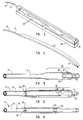
- FIG. 1 illustrates an apparatus which site-selectively reinforces a region of a catheter, the apparatus commonly referred to in this application as the reinforced catheter 10.
- Reinforced catheter 10 comprises a catheter 12 made of a compliant medical grade material with a longitudinal lumen 14 extending through a substantial length of catheter 12. A region of catheter 12 can be subjected to compressive forces if catheter 12 is placed in the vessel of a patient (not shown).
- the choice of material catheter 12 is made from is silicone rubber. This type of material is preferred in light of its biocompatible, compliable nature. Also, ease of catheters, made from silicone rubber, on bodily tissues as the catheters are inserted into a body, makes this choice of material ideal. This type of material, however, is discussed as an example of what catheters can be made from; the present invention is not limited to this choice of material.
- catheter 12 be an indwelling central venous access catheter.
- Catheter 12 is typically percutaneously implanted within a patient for a time period which can range from about ten minutes to about two years. Nevertheless, the present invention includes all types of catheters, and catheter 12 is not required to be an indwelling central venous access catheter.
- catheter 12 may have a two-way valve, but again this is not required.
- Two-way valve is located at the distal end 18 of catheter 12.
- Proximal end 20 of catheter 12 has only a general opening. The edges of the two-way valve remain in abutment and closed in a normal state. The two-way valve, however, responds to pressure differentials and will disengage to create an opening so that materials may pass through the two-way valve.
- catheter 12 can have a single lumen or catheter 12 can have more than one lumen. As illustrated in Figure 1, catheter 12 has only a single lumen 14.
- catheter 12 As an example of the compressive forces mentioned, it is known that if catheter 12 is implanted in the subclavian vein of a patient, catheter 12 travels in a very narrow triangular space bounded by the clavicle and first rib anteriorly and the anterior scalene muscle posteriorly.
- Catheter 12 inserted using the percutaneous subclavian route pass medial to the subclavian vein in an extremely narrow space bounded by the costo-clavicular ligament in the angle between the first rib and clavicle anteriorly and the subclavian vein posteriorly. It is at this angle (while outside the vein) where catheter 12 implanted by the subclavian route can become caught in a pincher-like pressure from movement over time involving the shoulder and clavicle.
- means are provided for site selectively reinforcing the aforesaid region of catheter 12 where the compressive forces are applied against catheter 12.
- the means are positioned within lumen 14 of catheter 12.
- Nonmetallic inner sleeve 22 having a proximal end 28 and a distal end 30 is inserted site-selectively within catheter 12.
- Nonmetallic inner sleeve 22 is tubular in structure. This construction is important so that nonmetallic inner sleeve 22 does not present an obstacle to the flow of fluids passing through lumen 14 of catheter 12. The passage of these fluids is critical to a patient.
- Nonmetallic inner sleeve 22 is capable of preventing catheter 12 from becoming partially or totally separated due to compressive forces generated by the body of a patient.
- nonmetallic inner sleeve 22 Also enabling the generally constant flow of a fluid through lumen 14 are the structural features of nonmetallic inner sleeve 22.
- proximal end 28 and distal end 30 of nonmetallic inner sleeve 22 have chamfered edges. The chamfered edges conform nonmetallic inner sleeve 22 to the configuration of the inside of catheter 12 to allow materials to travel unhindered through nonmetallic inner sleeve 22.
- Nonmetallic inner sleeve 22 can be comprised wholly of a single type of material or of different substances.
- nonmetallic inner sleeve 22 is comprised of polyurethane. This material is resistant to separation by compressive forces and maintains a conformational integrity.
- nonmetallic inner sleeve has been comprised of tetrafluoroethylene or fluorinated ethylene propylene. The present invention, however, is not limited to these constructions.
- nonmetallic inner sleeve 22 has an outer diameter greater than the inner diameter of catheter 12. In this way, when nonmetallic inner sleeve resides in lumen 14 of catheter 12, the inner walls of catheter 12 frictionally engages the exterior of nonmetallic inner sleeve. It is this frictional engagement which maintains the position of nonmetallic inner sleeve 22 relative to catheter 12.
- nonmetallic inner sleeve 22 maintains a constant connection between fractured or separated portions of catheter 12.
- nonmetallic inner sleeve 22 is disposed within lumen 14 of catheter 12. At first glance, it would seem to be easier to have catheter 12 disposed within nonmetallic inner sleeve 22 due to the larger outer diameter of nonmetallic inner sleeve 22 than the inner diameter of catheter 12. Positioning nonmetallic inner sleeve 22 could be done with relative ease by stretching the ends of catheter 12 slightly to sufficiently reduce the outer diameter of catheter 12 so that nonmetallic inner sleeve 22 could be slid into position about catheter 12.
- Nonmetallic inner sleeve 22 does not prevent stresses from being transmitted to catheter 12 when the two are disposed adjacent each other. Thus, should the reinforced catheter in the foregoing structural arrangement be subjected to compressive forces, catheter 12 will still partially or totally separate. At this critical point, if catheter 12 is removed from a patient (the most common removal procedure is to pull on the catheter and break a Dacron cuff loose from a patient's tissue) and catheter 12 is partially or totally separated, catheter 12 will stretch and pull out of nonmetallic inner sleeve 22.
- nonmetallic inner sleeve 22 and the distal end of catheter 12 are left within the patient. As previously discussed, once the compressive forces about nonmetallic inner sleeve 22 are relieved by body movement, these portions can be quickly carried into the heart. The resulting embolus can cause heart arrhythmias, and be a focal point for very serious infection in the cardiovascular system.
- the structural arrangement of the present invention prevents any such dangers from occurring to a patient.
- nonmetallic inner sleeve 22 disposed within catheter 12
- totally separated sections of catheter 12 cannot be pulled off of nonmetallic inner sleeve 22. This is due to the elongation and neck down of catheter 12, making catheter 12 even tighter on nonmetallic inner sleeve 22. Restriction on catheter 12, and not on nonmetallic inner sleeve 22 results in an accordion effect on catheter 12 over nonmetallic inner sleeve 22 which raises the frictional interface between the catheter 12 and nonmetallic inner sleeve 22.
- the inner diameter of catheter 12 is in the range from about 1,40 to 1,70 mm (.055 to .066 inches) and the outer diameter of nonmetallic inner sleeve 22 is in the range from about 1,80 to 1,96 mm (.071 to .077 inches).
- the outer diameter of nonmetallic inner sleeve 22 needs to be large enough to frictionally interface with the inner diameter of catheter 12. Nevertheless, the present invention is not limited to these dimensions.
- nonmetallic inner sleeve 22 is positioned in the range from about 25.4 mm to about 610 mm (about one inch to about two feet) from distal end 18 of catheter 12. In the most preferred embodiment, however, nonmetallic inner sleeve 22 is positioned about 38 mm (about 1.5 inches) from distal end 18 of catheter 12.
- nonmetallic inner sleeve 22 is in one embodiment of the present invention in the range from about 200 mm to about 216 mm (from about 8 inches to about 8.5 inches). In the most preferred embodiment, however, nonmetallic inner sleeve 22 is about 210 mm (about 8.25 inches) in length.
- Figure 1A illustrates the effect compressive forces have on a prior art catheter that is not reinforced.
- Compressive forces 32 are directed inwardly as indicated by arrow A.
- the conformation of catheter 12 in Figure 1A is distorted.
- Repeated infliction of compressive forces 32 on the outer surface of catheter 12 will wear down the body of catheter 12.
- the body of catheter 12 becomes brittle and can partially separate or totally separate.
- Figure 1 illustrates how reinforcing catheter 10 reacts to compressive forces 32.
- Figure 1 contains a cut-away view of the lumen 34 of nonmetallic inner sleeve 22 which changes its conformation when compressive forces 32 engage the body of reinforced catheter 10.
- lumen 14 of catheter 12 changes its conformation.
- catheter 12 remains in frictional engagement with nonmetallic inner sleeve 22 even if compressive forces 32 partially or totally separate catheter 12.
- nonmetallic inner sleeve 22 is slightly larger than lumen 14 of catheter 12, the body of catheter 12 must be expanded to accept nonmetallic inner sleeve 22. Once nonmetallic inner sleeve 22 is positioned within catheter 12, the body of catheter 12 attempts to regain its non-expanded conformation and presses inwardly on nonmetallic inner sleeve 22. This result has the effect of keeping nonmetallic inner sleeve 22 in place within lumen 14 of catheter 12. In this way, once positioned to counteract generated compressive forces 32, nonmetallic inner sleeve 22 will stay in the same place so as not to slide or move.
- catheter 12 is separated into a first section 40 and a second section 42 by compressive forces 32.
- the tubular structure of nonmetallic inner sleeve 22 extends the communication between the lumen 44 of first section 40 and the lumen 46 of second section 42 of separated catheter 12.
- the separated area 45 can be fairly close together as illustrated in Figure 1B; however, this may not occur in all instances.
- first section 40 and second section 42 of severed catheter 12 results because the outer diameter of nonmetallic inner sleeve 22 is slightly larger than the inner diameter of catheter 12.
- catheter 12 presses and frictionally engages the exterior of nonmetallic inner sleeve 22.
- first section 40 and second section 42 of catheter 12 remain in frictional engagement with nonmetallic inner sleeve 22 which continues to provide the communication between lumen 44 of first section 40 and lumen 46 of second section 42 of separated catheter 12.
- Torsion involves the twisting or wrenching of the catheter by the exertion of forces tending to turn one end or part about a longitudinal axis while the other is held fast or turned in the opposite direction.
- Any twisting or wrenching of a catheter can only result in the damage to sensitive bodily layers of a patient through which a catheter resides. Under the circumstances of the present invention, it is compressive forces which the reinforced catheter experiences and is primarily directed to correct. Nevertheless, the area of site-selective reinforcement would also be torsionally resistant.
- catheter 12 is preformed in relation to nonmetallic inner sleeve 22.
- Various individuals have attempted to increase the torsional rigidity of catheters by taking a tubular structure and forming a catheter body around the tubular structure.
- the dual-body structure of the resulting catheter by this "after-forming" procedure increases the torsional rigidity of the structure.
- the tubular structure of the after-formed catheter body has been comprised of such rigid materials such as metals.
- nonmetallic inner sleeve 22 is inserted within a catheter which has already been formed, and therefore reinforced catheter 10 is quite different from the catheter created by the after-formed procedure.
- Nonmetallic inner sleeve 22 is site-selectively positioned within catheter 12 to reinforce against compressive forces 32 unlike the after-formed catheter.
- nonmetallic inner sleeve 22 substantially increases the torsional rigidity of catheter 12 as would an after-formed catheter.
- an after-formed catheter and nonmetallic inner sleeve 22 can be shown by a further examination of their methods of manufacture.
- the after-formed catheter is formed by molding an outer layer around a tubular structure as previously discussed.
- the present application discloses two separate methods that have been used to manufacture reinforced catheter 10: (1) the "chemical soak,” and (2) the “pressurized gas” methods. Both these methods, as will be seen, vary greatly from the method of manufacturing the after-formed catheter.
- the present invention as it pertains to the chemical soak method can be understood with reference to Figure 2.
- Figure 2 illustrates this method for site-selectively reinforcing a portion of catheter 12 in its preferred embodiment.
- the first step of the chemical soak method involves exposing a length of catheter 12 to a chemical compound which causes the exposed portion of catheter 12 to swell.
- This chemical treatment step is important because in this way, lumen 14 of catheter 12, which before the chemical treatment was of a diameter smaller than nonmetallic inner sleeve 22, is expanded to a diameter greater than nonmetallic inner sleeve 22. This result allows nonmetallic inner sleeve 22 to be slidably engaged within lumen 14 of catheter 12.
- nonmetallic inner sleeve 22 can be inserted in any expanded opening, and catheter 12 has proximal end 20 and distal end 18, an option exists for nonmetallic inner sleeve 22 to be inserted through an opening other than at distal end 18 of catheter 12.
- the distal end of a catheter may be structurally sensitive, e.g . if a two-way valve exists. In the preferred embodiment of the present invention, therefore, insertion of nonmetallic inner sleeve 22 through expanded proximal end 20 of catheter 12 alleviates any potential dangers were nonmetallic inner sleeve 22 to be inserted through distal end 18 of catheter 12.
- the chemical which has been found to have catheter expanding capabilities and is the chemical employed in the preferred embodiment of the chemical soak method is freon.
- Freon is naturally a liquid at room temperature, but has a high vapor pressure (affinity to become gas). It is the application of this liquid which thereby causes the walls of catheter 12 to swell as the freon is absorbed.
- freon It is the high vapor pressure of freon that allows catheter 12 to return to its normal size.
- the freon contained in the walls of catheter 12 evaporates, and the swelling is reduced.
- the use of freon to alter the size of the diameter of catheter 12 is beneficial because freon does not leave a residue upon evaporation.
- Freon is not the only chemical which has catheter expanding capabilities, and the present invention is not intended to comprise only freon. It has been noted that cyclohexanone, methyl ethyl ketone, and isopropyl alcohol may also be employed in the present invention. The foregoing are provided as examples, and are not meant to limit the scope of the chemicals having catheter expanding capabilities that may be employed in the present invention.
- freon 48 is placed in a container 50 and then a portion of catheter 12 is exposed to freon 48.
- catheter 12 is exposed to freon 48 for a range of about one to about ten minutes. In the preferred embodiment of the present invention, catheter 12 is exposed to freon 48 for at least about five minutes.
- Figure 3 is meant to illustrate the effect the chemical treatment has upon catheter 12 after exposure to freon 48. Expanded portions 52 of catheter 12 exposed to the chemical treatment are enlarged in relation to the portions of catheter 12 not exposed to the chemical treatment. The chemical is absorbed in the walls of catheter 12, and results in swelling. Because the body of catheter 12 is expanded in diameter, lumen 14 of catheter 12 is likewise increased in diameter to a diameter greater than nonmetallic inner sleeve 22.
- nonmetallic inner sleeve 22 is advanced through lumen 14 of expanded portion 52 of catheter 12 immersed in freon 48 to a site-selective position which will experience compressive forces 32.
- nonmetallic inner sleeve 22 is placed on a rod 54 as shown in Figure 4. Then rod 54, and therefore nonmetallic inner sleeve 22, are advanced within lumen 14 of catheter 12. The direction of the insertion is indicated by arrow B of Figure 4.
- nonmetallic inner sleeve 22 can be advanced by rod 54 throughout exposed portion 52 of catheter 12 until nonmetallic inner sleeve 22 becomes positioned at the selected site.
- nonmetallic inner sleeve 22 is inserted through lumen 14 of catheter 12 to a site-selected position, however, nonmetallic inner sleeve 22 is not able to become disposed in that portion of catheter 12 that has not been immersed in freon 48. That portion of catheter 12 that has not been immersed in freon 48 has an inner diameter that is smaller than the outer diameter of nonmetallic inner sleeve 22.
- rod 54 may be withdrawn from nonmetallic inner sleeve 22 in the direction shown by arrow C in Figure 5.
- Nonmetallic inner sleeve 22 is thereafter in the site selected position which is subject to compressive forces 32.
- the chemical soak method comprises the step of drying expanded portions 52 of catheter 12 exposed to the chemical compound to return expanded portions 52 of catheter 12 to their original size before exposure and leaving nonmetallic inner sleeve 22 within lumen 14 of catheter 12.
- Catheter 12 having nonmetallic inner sleeve 22 within lumen 14 of catheter 12 is thereafter reinforced against compressive forces 32 to prevent possible partial or total separation of catheter 12.
- the present invention can also be made by a pressurized gas method which can be understood with reference to Figure 7.
- This method comprises advancing nonmetallic inner sleeve 22, placed on a hollow rod 58 which is connected to a pressurizing gas source 60, through lumen 14 of catheter 12 having distal end 18 capable of being inserted within a patient and a proximal end 20.
- hollow rod 58 remote from nonmetallic inner sleeve 22, is connected to low volume, high pressure gas source 60 via an air line 62.
- pressurized air can be directed through the air line 62 out the end of hollow rod 58.
- air is not the only gas which may be directed under pressure through hollow rod 58, other gases may be equally employed.
- a range from about 5.4 to 6.2 atmospheres (about 80-90 psi) of gas is introduced to expand lumen 14 of catheter 12.
- the present invention comprises the further step of soft-clamping catheter 12 at a position intermediate the desired reinforcement site and the opening 64 at distal end 18 of catheter 12. Because catheter 12 has an opening at distal end 18 of catheter 12, should air be introduced within lumen 14 at proximal end 20 of catheter 12, air would escape through the opening. In this case, pressurized air passing through hollow rod 58 could not inflate and slightly enlarge catheter 12 to allow nonmetallic inner sleeve 22 to be advanced within catheter 12.
- Soft-clamp 66 is illustrated in Figure 7.
- the clamp is referred to as "soft" in light of its structural feature. Whereas most clamps have angled edges which can possibly injure a catheter, soft-clamp 66 has rounded edges which provide a short-term compressed effect on catheter 12 to block lumen 14. Blocked lumen 14 enables hollow rod 58 to inflate and slightly enlarge a portion of catheter 12.
- the method also comprises the step of advancing nonmetallic inner sleeve 22 to an area of catheter 12 experiencing compressive forces 32, catheter 12 expanding in response to the introduction of the pressurized air to allow the advancement of nonmetallic inner sleeve 22.
- the outer diameter of nonmetallic inner sleeve 22 being greater than the inner diameter of catheter 12 before catheter 12 is expanded.
- Nonmetallic inner sleeve 22 is advanced at least a portion of the way through catheter 12.
- hollow rod 58 with nonmetallic inner sleeve 22 mounted thereon is entered into and advanced along lumen 14 of catheter 12 from open proximal end 20 thereof.
- the pressurized air passing through hollow rod 58 inflates and slightly enlarges a portion 64 of catheter 12.
- Enlarged portion 68 of catheter 12 creates an enlarged lumen through which nonmetallic inner sleeve 22 may be passed.
- air at a high pressure and controlled volume is utilized to partially inflate catheter 12 while at the same time providing a nontoxic, low-friction interface layer between nonmetallic inner sleeve 22 and the inner surface of lumen 14 of catheter 12.
- a catheter having a Groshong® valve 70 may be employed. Because this type of valve is responsive to pressure differentials, there is a possibility that the Groshong valve could be damaged by the pressurized gas required by the present invention. Therefore, as previously discussed, it is preferred that the present invention comprise the further step of soft-clamping catheter 12 at a position intermediate the desired reinforcement site and the openings at distal end 18 of catheter 12.
- catheter 12 Once catheter 12 has been soft-clamped, hollow rod 58 used to advance nonmetallic inner sleeve 22 to a site-selective position in catheter 12 is withdrawn from nonmetallic inner sleeve 22 and catheter 12. Nonmetallic inner sleeve 22 is left within catheter 12 which returns to a normal size after hollow rod 58 has been removed.
- Catheter 12 having nonmetallic inner sleeve 22 within lumen 14 of catheter 12 is reinforced against compressive forces 32 to prevent partial separation to allow for the extravasation or total separation leading to embolization.
- Either the rod 54 (see Figures 4 to 6) or the hollow rod 58 (see Figures 8 to 10) may be equipped with a sliding ring or cylinder which may be employed to aid withdrawal of the rod 54 or 58 from engagement with the sleeve 22.
- nonmetallic inner sleeve 22 is advanced within lumen 14 of catheter 12 in the range from about 25 mm to about 610 mm (from about one inch to about two feet) from distal end 18 of catheter 12. In the preferred embodiment, however, nonmetallic inner sleeve 22 is advanced within lumen 14 of catheter 12 about 25 mm to about 38 mm (about one and one-half inches) from distal end 18 of catheter 12.
- Implantation of reinforced catheter 10 within the body of a patient can be accomplished in the same way other catheter known to the art are implanted. Most often, implantation will involve the use of some type of induction system employing a needle or trocar and an introducer.
- the present invention provides apparatus and methods for reducing the susceptibility of implanted catheters via the percutaneous subclavian route to damaging stresses due to body movement by reinforcing site-selectively the walls of the catheter.
- the present invention provides apparatus and methods for reinforcing a catheter disposed in an area subject to damaging stresses due to body movement which can prevent embolization of the implanted catheter by maintaining a connection between stress-induced severed catheter portions should separation or fractionation occur. Frictional engagement between each of the severed catheter portions surrounding the reinforcing inner sleeve acts to maintain the connection between the severed catheter portions.
- the present invention provides apparatus and methods for reinforcing a catheter disposed in an area subject to damaging stresses due to body movement which will have the capacity to place and use the catheter without a major deviation from currently existing standard practices.
- the present invention provides apparatus and methods for reinforcing a catheter disposed in an area subject to damaging stresses due to body movement which will allow the insertion of a reinforcing inner sleeve which will be soft enough to easily follow the normal path of a catheter as well as preventing partial or total catheter separation due to the pinching action of the clavicle and first rib.
- the present invention provides apparatus and methods f or reinforcing a catheter disposed in an area subject to damaging stresses due to body movement which is easy to handle and manipulate by medical personnel and will not harden or deteriorate over time.
Landscapes
- Health & Medical Sciences (AREA)
- Life Sciences & Earth Sciences (AREA)
- Biophysics (AREA)
- Pulmonology (AREA)
- Engineering & Computer Science (AREA)
- Anesthesiology (AREA)
- Biomedical Technology (AREA)
- Heart & Thoracic Surgery (AREA)
- Hematology (AREA)
- Animal Behavior & Ethology (AREA)
- General Health & Medical Sciences (AREA)
- Public Health (AREA)
- Veterinary Medicine (AREA)
- Media Introduction/Drainage Providing Device (AREA)
- Infusion, Injection, And Reservoir Apparatuses (AREA)
Claims (24)
- Katheter, der in einem begrenzten Bereich desrselben Druckkräften ausgesetzt werden soll, die durch den Körper eines Patienten erzeugt werden, wenn der Katheter darin verweilt, wobei der Katheter einen Katheterschlauch (12) aufweist, der aus einem nachgiebigen, für medizinische Zwecke geeignetem Material hergestellt ist, wobei der Katheterschlauch ein distales und ein proximales Ende und einen länglichen Hohlraum (14) aufweist, der sich über eine beträchtliche Länge des Katheterschlauchs erstreckt;
dadurch gekennzeichnet, daß eine Verstärkungseinrichtung (22) in dem Hohlraum (14) des Katheterschlauchs (12) angeordnet ist, um den begrenzten Bereich an einer wählbaren Stelle zu verstärken. - Katheter nach Anspruch 1, dadurch gekennzeichnet, daß die Verstärkungseinrichtung eine nichtmetallische, nachgiebige, innere röhrenförmige Hülse (22) aufweist, die ausgewählt innerhalb wenigstens eines Abschnitts des Hohlraums (14) des Katheterschlauchs eingeführt ist, und die Druckkräften widerstehen kann, die durch den Körper eines Patienten erzeugt werden.
- Katheter nach Anspruch 2, dadurch gekennzeichnet, daß die röhrenförmige Hülse (22) in dem Hohlraum (14) des Katheterschlauchs in einem Bereich von etwa 25 mm bis etwa 210 mm (von etwa 1 Inch bis etwa 2 Fuß) von dem distalen Ende (18) des Katheterschlauchs angeordnet ist.
- Katheter nach einem der Ansprüche 1 bis 3, dadurch gekennzeichnet, daß, wenn der Katheterschlauch (12) durch die Haut hindurch in den Körper eines Patienten implantiert wird, der Katheterschlauch (12) derart aufgebaut ist, daß ein Reißen von empfindlichen Körpergeweben vermieden wird, wenn er derart implantiert wird.
- Katheter nach einem der Ansprüche 1 bis 4, dadurch gekennzeichnet, daß der Katheter ein durch die Haut hindurch eingesetzter, verweilender zentraler Venenkatheter ist.
- Katheter nach einem der Ansprüche 1 bis 5, dadurch gekennzeichnet, daß der Katheterschlauch aus Silikongummi besteht und einen Durchmesser in einem Bereich von etwa 1,27 mm bis etwa 1,67 mm aufweist, wobei der verweilende Katheterschlauch den Bereich zwischen dem Schlüsselbein und der ersten Rippe des Patienten durchquert.
- Vorrichtung zum Verstärken eines Bereichs eines Katheters an einer wählbaren Stelle nach Anspruch 6, dadurch gekennzeichnet, daß der begrenzte Bereich des Katheters Druckkräften unterliegt, die durch den Bereich zwischen dem Schlüsselbein und der ersten Rippe des Patienten erzeugt werden.
- Katheter nach den Ansprüchen 2 bis 7, dadurch gekennzeichnet, daß die röhrenförmige Hülse einen Durchmesser in einem Bereich von etwa 1,80 mm bis etwa 1,96 mm (von etwa 0,071 Inch bis etwa 0,077 Inch) aufweist.
- Katheter nach einem der Ansprüche 2 bis 8, dadurch gekennzeichnet, daß die röhrenförmige Hülse aus weichem, für medizinische Zwecke geeignetem Silikongummi hergestellt ist und eine Länge in einem Bereich von etwa 200 mm bis etwa 216 mm (von etwa 8 Inch bis etwa 8,5 Inch) aufweist.
- Katheter nach einem der Ansprüche 1 bis 9, dadurch gekennzeichnet, daß der Katheterschlauch entweder einen einzigen Hohlraum oder mehrere Hohlräume aufweist.
- Katheter nach einem der Ansprüche 1 bis 10, dadurch gekennzeichnet, daß sich an dem distalen Ende (18) des Katheterschlauchs ein Zweiwegeventil befindet.
- Katheter nach einem der Ansprüche 1 bis 11, dadurch gekennzeichnet, daß der Katheterschlauch (12) einen Hohlraum (14) mit einem Ventil aufweist, das wahlweise den Eintritt oder den Austritt von Flüssigkeiten in den oder aus dem Hohlraum des Katheterschlauchs gewähren kann.
- Katheter nach einem der Ansprüche 1 bis 12, wobei der Katheter derart aufgebaut ist, daß er durch die Haut hindurch in den Körper eines Patienten für eine Zeitdauer in einem Bereich von etwa 10 Minuten bis etwa 2 Jahren implantiert werden kann.
- Katheter nach einem der Ansprüche 1 bis 13, wobei der Katheterschlauch derart aufgebaut ist, daß er aufgrund von Brüchen in dem Katheterschlauch in dem begrenzten Bereich des Katheters keine Embolie auslöst.
- Verfahren zum Verstärken eines begrenzten Abschnitts eines Katheters an einer wählbaren Stelle, der in dem begrenzten Abschnitt Druckkräften ausgesetzt werden soll, die durch den Körper eines Patienten erzeugt werden, wenn der Katheter darin verweilt, wobei der Katheter ein erstes und ein zweites Ende und einen Hohlraum aufweist, der sich von einem ersten Abschnitt der Länge des Katheters von dessen erstem Ende wenigstens bis zu dem begrenzten Abschnitt erstreckt, wobei das Verfahren gekennzeichnet ist durch die Schritte:(a) Veranlassen einer Vergrößerung des inneren Durchmessers des Hohlraums (14) in dem ersten Abschnitt des Katheters von seinem ursprünglichen inneren Durchmesser auf einen vergrößerten inneren Durchmesser;(b) Vorschieben einer verstärkenden Hülse (22) durch den Hohlraum in dem ersten Abschnitt des Katheters zu dem begrenzten Bereich, wobei die verstärkende Hülse einen äußeren Durchmesser aufweist, der größer ist als der ursprüngliche innere Durchmesser des Hohlraums in dem ersten Abschnitt des Katheters und geringer ist als der vergrößerte innere Durchmesser des Hohlraums;(c) Zurücklassen der verstärkenden Hülse (22) in dem Hohlraum in dem begrenzten Bereich; und(d) Ermöglichen eines Rückkehrens des inneren Durchmessers des Hohlraums in dem ersten Abschnitt des Katheters von dem vergrößerten inneren Durchmesser zu dem ursprünglichen inneren Durchmesser, wodurch die verstärkende Hülse (22) innerhalb des Hohlraums (14) des Katheters in dem begrenzten Bereich derart gesichert wird, daß sie den Katheter gegen die Druckkräfte verstärkt, die in dem begrenzten Bereich aufgebracht werden.
- Verfahren nach Anspruch 15, dadurch gekennzeichnet, daß das Veranlassen einer Vergrößerung des inneren Durchmessers des Hohlraums (14) in dem ersten Abschnitt des Katheters den Schritt aufweist: der erste Abschnitt des Katheters wird einer chemischen Verbindung ausgesetzt, die den ersten Abschnitt des Katheterschlauchs anschwellen läßt.
- Verfahren nach einem der Ansprüche 15 oder 16, dadurch gekennzeichnet, daß der erste Abschnitt des Katheters in eine chemische Verbindung, die Freon aufweist, eingetaucht wird.
- Verfahren nach einem der Ansprüche 15 bis 17, dadurch gekennzeichnet, daß die verstärkende Hülse (22) durch den Hohlraum in dem ersten Abschnitt des Katheters unter Verwendung einer Vorschubstange (54) vorgeschoben wird.
- Verfahren nach einem der Ansprüche 15 bis 17, dadurch gekennzeichnet, daß das Verfahren ferner den Schritt aufweist: vor dem Schritt des Vorschiebens der verstärkenden Hülse wird der Katheterschlauch an der Seite des begrenzten Bereichs, die dem ersten Ende gegenüberliegt, weich geklammert.
- Verfahren nach Anspruch 15, dadurch gekennzeichnet, daß das Veranlassen einer Vergrößerung des inneren Durchmessers des Hohlraums (14) in dem ersten Abschnitt des Katheters folgende Schritte aufweist:(a) Weiches Klammern des Katheters an der Seite des begrenzten Bereichs, die dem ersten Ende gegenüberliegt;(b) Befestigen einer hohlen verstärkenden Hülse (22) an einem Ende einer hohlen Vorschubstange (58);(c) Verbinden des anderen Endes der hohlen Vorschubstange mit einer Gasquelle mit niedrigem Volumen und hohem Druck; und(d) Einführen der verstärkenden Hülse (22) auf der Vorschubstange (58) in den Hohlraum des Katheters von dessen erstem Ende aus, wobei sich der innere Durchmesser des Hohlraums des Katheters wegen der Einführung von Druckgas durch die hohle Stange und die verstärkende Hülse ausdehnt.
- Verfahren nach Anspruch 20, dadurch gekennzeichnet, daß Gas bei einem Druck in einem Bereich von etwa 5,4 bis etwa 6,2 Atmosphären (von etwa 80 psi bis etwa 90 psi) durch die hohle Vorschubstange und die verstärkende Hülse eingeführt wird, um den Hohlraum des Katheters auszudehnen.
- Verfahren nach einem der Ansprüche 18 bis 21, dadurch gekennzeichnet, daß ein Ring oder ein Zylinder an der Vorschubstange derart angebracht ist, daß er die Anordnung der verstärkenden Hülse in dem begrenzten Bereich des Katheters unterstützt, oder das Zurückziehen der Stange (54, 58) von dem Eingriff mit der Hülse (22) unterstützt.
- Verfahren nach einem der Ansprüche 15 bis 22, dadurch gekennzeichnet, daß die verstärkende Hülse einen äußeren Durchmesser in einem Bereich von etwa 1,8 mm bis etwa 1,96 mm (von etwa 0,071 Inch bis etwa 0,077 Inch) aufweist, und der ursprüngliche innere Durchmesser des Hohlraums des Katheterschlauchs in einem Bereich von etwa 1,4 mm bis etwa 1,7 mm (von etwa 0,055 Inch bis etwa 0,066 Inch) liegt.
- Verfahren nach einem der Ansprüche 16 bis 23, dadurch gekennzeichnet, daß der begrenzte Bereich, zu dem die verstärkende Hülse vorgeschoben wird, dem Bereich zwischen dem Schlüsselbein und der ersten Rippe eines Patienten entspricht, wenn der Katheter darin verweilt.
Applications Claiming Priority (2)
| Application Number | Priority Date | Filing Date | Title |
|---|---|---|---|
| US66578791A | 1991-03-07 | 1991-03-07 | |
| US665787 | 1991-03-07 |
Publications (2)
| Publication Number | Publication Date |
|---|---|
| EP0502664A1 EP0502664A1 (de) | 1992-09-09 |
| EP0502664B1 true EP0502664B1 (de) | 1996-04-10 |
Family
ID=24671577
Family Applications (1)
| Application Number | Title | Priority Date | Filing Date |
|---|---|---|---|
| EP92301712A Expired - Lifetime EP0502664B1 (de) | 1991-03-07 | 1992-02-28 | Lagenselektiver, verstärkter Katheter und Verfaren für die Herstellung des verstärkten Katheters |
Country Status (6)
| Country | Link |
|---|---|
| US (1) | US5389091A (de) |
| EP (1) | EP0502664B1 (de) |
| JP (1) | JPH04319363A (de) |
| CA (1) | CA2062000A1 (de) |
| DE (1) | DE69209707T2 (de) |
| ES (1) | ES2088538T3 (de) |
Cited By (3)
| Publication number | Priority date | Publication date | Assignee | Title |
|---|---|---|---|---|
| US7458955B2 (en) | 1997-03-11 | 2008-12-02 | Owens Warren D | Catheter having insertion control mechanism |
| US9028441B2 (en) | 2011-09-08 | 2015-05-12 | Corpak Medsystems, Inc. | Apparatus and method used with guidance system for feeding and suctioning |
| US9131956B2 (en) | 2005-01-13 | 2015-09-15 | Corpak Medsystems, Inc. | Tubing assembly and signal generator placement control device and method for use with catheter guidance systems |
Families Citing this family (24)
| Publication number | Priority date | Publication date | Assignee | Title |
|---|---|---|---|---|
| US6361528B1 (en) | 1999-04-05 | 2002-03-26 | Acist Medical Systems, Inc. | Dynamically compliant catheter |
| JP4184794B2 (ja) * | 2001-02-05 | 2008-11-19 | ビアカー・インコーポレーテッド | 僧帽弁の機能を改良するための方法及び装置 |
| WO2002062263A2 (en) | 2001-02-05 | 2002-08-15 | Viacor, Inc. | Apparatus and method for reducing mitral regurgitation |
| CA2668308A1 (en) * | 2001-03-05 | 2002-12-05 | Viacor, Incorporated | Apparatus and method for reducing mitral regurgitation |
| CA2441886C (en) * | 2001-03-23 | 2009-07-21 | Viacor, Incorporated | Method and apparatus for reducing mitral regurgitation |
| US7186264B2 (en) * | 2001-03-29 | 2007-03-06 | Viacor, Inc. | Method and apparatus for improving mitral valve function |
| US20030078654A1 (en) * | 2001-08-14 | 2003-04-24 | Taylor Daniel C. | Method and apparatus for improving mitral valve function |
| US7052487B2 (en) * | 2001-10-26 | 2006-05-30 | Cohn William E | Method and apparatus for reducing mitral regurgitation |
| US7125420B2 (en) * | 2002-02-05 | 2006-10-24 | Viacor, Inc. | Method and apparatus for improving mitral valve function |
| US20040054350A1 (en) * | 2002-09-17 | 2004-03-18 | Shaughnessy Michael C. | Enteral feeding unit having a reflux device and reflux method |
| US7601141B2 (en) * | 2002-11-26 | 2009-10-13 | Nexus Medical, Llc | Pressure actuated flow control valve |
| US20040116899A1 (en) * | 2002-12-16 | 2004-06-17 | Shaughnessy Michael C. | Bolus for non-occluding high flow enteral feeding tube |
| US20060136053A1 (en) * | 2003-05-27 | 2006-06-22 | Rourke Jonathan M | Method and apparatus for improving mitral valve function |
| WO2005009286A2 (en) * | 2003-07-23 | 2005-02-03 | Viacor, Inc. | Method and apparatus for improving mitral valve function |
| US20070060898A1 (en) * | 2005-09-07 | 2007-03-15 | Shaughnessy Michael C | Enteral medical treatment assembly having a safeguard against erroneous connection with an intravascular treatment system |
| US8986253B2 (en) | 2008-01-25 | 2015-03-24 | Tandem Diabetes Care, Inc. | Two chamber pumps and related methods |
| US8408421B2 (en) | 2008-09-16 | 2013-04-02 | Tandem Diabetes Care, Inc. | Flow regulating stopcocks and related methods |
| CA2737461A1 (en) | 2008-09-19 | 2010-03-25 | Tandem Diabetes Care, Inc. | Solute concentration measurement device and related methods |
| US7967797B2 (en) * | 2009-05-19 | 2011-06-28 | Nexus Medical, Llc | Intravascular valve component with improved valve positioning |
| US8926561B2 (en) | 2009-07-30 | 2015-01-06 | Tandem Diabetes Care, Inc. | Infusion pump system with disposable cartridge having pressure venting and pressure feedback |
| EP2688605A4 (de) | 2011-03-24 | 2014-09-10 | Bard Inc C R | Befestigung und schutz einer implantierten medizinischen vorrichtung |
| US9180242B2 (en) | 2012-05-17 | 2015-11-10 | Tandem Diabetes Care, Inc. | Methods and devices for multiple fluid transfer |
| US9173998B2 (en) | 2013-03-14 | 2015-11-03 | Tandem Diabetes Care, Inc. | System and method for detecting occlusions in an infusion pump |
| JP7723536B2 (ja) * | 2021-08-27 | 2025-08-14 | テルモ株式会社 | シースおよび医療用組立体 |
Family Cites Families (34)
| Publication number | Priority date | Publication date | Assignee | Title |
|---|---|---|---|---|
| US2308484A (en) * | 1939-01-16 | 1943-01-19 | Davol Rubber Co | Catheter |
| NL101512C (de) * | 1954-10-04 | |||
| US3010194A (en) * | 1958-11-06 | 1961-11-28 | Rubberol Coverings Inc | Apparatus for covering rolls with flexible tubing |
| US3426744A (en) * | 1964-02-27 | 1969-02-11 | United Aircraft Corp | Heart pump cannula |
| US3485234A (en) * | 1966-04-13 | 1969-12-23 | Cordis Corp | Tubular products and method of making same |
| US3630207A (en) * | 1969-08-08 | 1971-12-28 | Cutter Lab | Pericardial catheter |
| US4291454A (en) * | 1979-09-04 | 1981-09-29 | The United States Of America As Represented By The Secretary Of The Navy | Rubber boot expander |
| US4425919A (en) * | 1981-07-27 | 1984-01-17 | Raychem Corporation | Torque transmitting catheter apparatus |
| US4690175A (en) * | 1981-11-17 | 1987-09-01 | Kabushiki Kaisha Medos Kenkyusho | Flexible tube for endoscope |
| JPS5886129A (ja) * | 1981-11-17 | 1983-05-23 | 旭光学工業株式会社 | 内視鏡の可撓管及びその製造方法 |
| CA1186192A (en) * | 1982-01-27 | 1985-04-30 | David S. Hickey | Urethral catheter |
| US4431031A (en) * | 1982-03-29 | 1984-02-14 | Amco Corporation | Pre-rinse hose |
| US4498473A (en) * | 1982-12-07 | 1985-02-12 | Gereg Gordon A | Variable stiffness tracheal tube |
| US4549879A (en) * | 1983-05-03 | 1985-10-29 | Catheter Technology Corporation | Valved two-way catheter |
| US4577543A (en) * | 1983-08-18 | 1986-03-25 | American Hospital Supply Corporation | Construction of a monolithic reinforced catheter with flexible portions |
| JPS60126170A (ja) * | 1983-12-14 | 1985-07-05 | テルモ株式会社 | カテ−テルとその製造方法 |
| US4547193A (en) * | 1984-04-05 | 1985-10-15 | Angiomedics Incorporated | Catheter having embedded multi-apertured film |
| US4551292A (en) * | 1984-04-05 | 1985-11-05 | Angiomedics, Inc. | Method for making a catheter with a soft, deformable tip |
| US4723947A (en) * | 1986-04-09 | 1988-02-09 | Pacesetter Infusion, Ltd. | Insulin compatible infusion set |
| US4676229A (en) * | 1986-04-09 | 1987-06-30 | Welch Allyn, Inc. | Biopsy channel for an endoscope |
| US4776844A (en) * | 1986-05-02 | 1988-10-11 | Olympus Optical Co., Ltd. | Medical tube |
| US4713049A (en) * | 1986-08-05 | 1987-12-15 | Medical Engineering Corporation | Ureteral stent kit |
| US4775371A (en) * | 1986-09-02 | 1988-10-04 | Advanced Cardiovascular Systems, Inc. | Stiffened dilatation catheter and method of manufacture |
| US4753640A (en) * | 1986-10-06 | 1988-06-28 | Catheter Technology Corporation | Catheters and methods |
| US4748982A (en) * | 1987-01-06 | 1988-06-07 | Advanced Cardiovascular Systems, Inc. | Reinforced balloon dilatation catheter with slitted exchange sleeve and method |
| US4817613A (en) * | 1987-07-13 | 1989-04-04 | Devices For Vascular Intervention, Inc. | Guiding catheter |
| US4900314A (en) * | 1988-02-01 | 1990-02-13 | Fbk International Corporation | Collapse-resistant tubing for medical use |
| US4917670A (en) * | 1988-03-22 | 1990-04-17 | Hurley Ronald J | Continuous spinal anesthesia administering apparatus and method |
| US4994047A (en) * | 1988-05-06 | 1991-02-19 | Menlo Care, Inc. | Multi-layer cannula structure |
| US4875468A (en) * | 1988-12-23 | 1989-10-24 | Welch Allyn, Inc. | Elastomer-ePTFE biopsy channel |
| US4973319A (en) * | 1989-05-10 | 1990-11-27 | Therex Corp. | Slit valve medical catheter |
| US4955862A (en) * | 1989-05-22 | 1990-09-11 | Target Therapeutics, Inc. | Catheter and catheter/guide wire device |
| CA2030638C (en) * | 1990-01-10 | 1996-05-28 | Sakharam D. Mahurkar | Reinforced multiple-lumen catheter |
| US5061257A (en) * | 1990-04-30 | 1991-10-29 | Cordis Corporation | Apertured, reinforced catheter |
-
1992
- 1992-02-27 CA CA002062000A patent/CA2062000A1/en not_active Abandoned
- 1992-02-28 DE DE69209707T patent/DE69209707T2/de not_active Expired - Fee Related
- 1992-02-28 ES ES92301712T patent/ES2088538T3/es not_active Expired - Lifetime
- 1992-02-28 EP EP92301712A patent/EP0502664B1/de not_active Expired - Lifetime
- 1992-03-02 JP JP4044677A patent/JPH04319363A/ja active Pending
-
1993
- 1993-01-15 US US08/006,435 patent/US5389091A/en not_active Expired - Lifetime
Cited By (4)
| Publication number | Priority date | Publication date | Assignee | Title |
|---|---|---|---|---|
| US7458955B2 (en) | 1997-03-11 | 2008-12-02 | Owens Warren D | Catheter having insertion control mechanism |
| US9131956B2 (en) | 2005-01-13 | 2015-09-15 | Corpak Medsystems, Inc. | Tubing assembly and signal generator placement control device and method for use with catheter guidance systems |
| US9579488B2 (en) | 2005-01-13 | 2017-02-28 | Corpak Medsystems, Inc. | Tubing assembly and signal generator placement control device and method for use with catheter guidance systems |
| US9028441B2 (en) | 2011-09-08 | 2015-05-12 | Corpak Medsystems, Inc. | Apparatus and method used with guidance system for feeding and suctioning |
Also Published As
| Publication number | Publication date |
|---|---|
| DE69209707D1 (de) | 1996-05-15 |
| JPH04319363A (ja) | 1992-11-10 |
| DE69209707T2 (de) | 1996-10-17 |
| ES2088538T3 (es) | 1996-08-16 |
| US5389091A (en) | 1995-02-14 |
| EP0502664A1 (de) | 1992-09-09 |
| CA2062000A1 (en) | 1992-09-08 |
Similar Documents
| Publication | Publication Date | Title |
|---|---|---|
| EP0502664B1 (de) | Lagenselektiver, verstärkter Katheter und Verfaren für die Herstellung des verstärkten Katheters | |
| JP3660358B2 (ja) | カテーテル法のアクセスのための装置 | |
| EP1301235B1 (de) | Medizinische vorrichtung mit geflecht und spule | |
| US4950232A (en) | Cerebrospinal fluid shunt system | |
| US4624657A (en) | Medical devices having inflatable portions | |
| US6045734A (en) | Process of making a catheter | |
| US5466230A (en) | Catheter sheath introducer with strain relief | |
| EP2441488B1 (de) | Ballonkathetersystem und verfahren zur konstruktion | |
| US5234425A (en) | Variable diameter sheath method and apparatus for use in body passages | |
| DE69930871T2 (de) | Einführhülse | |
| JP3649734B2 (ja) | 脳治療用拡張器 | |
| CA2283827C (en) | Balloon catheter for puncturing, medical tube introducing device using the catheter and method for use thereof | |
| US20020165581A1 (en) | Vascular sealing device and method | |
| JP2000512874A (ja) | 多管腔カテーテルおよびその製造方法 | |
| US11642498B2 (en) | Isolating drainage catheter | |
| AU2001273446A1 (en) | Medical device with braid and coil | |
| US20240041465A1 (en) | Spiral-forming balloon for coronary sinus use | |
| CN221786475U (zh) | 一种血栓拦截器 | |
| JP2001238956A (ja) | バルーン付カテーテル | |
| Jensen et al. | Double-lumen balloon catheter | |
| JP2001269410A (ja) | バルーンカテーテル |
Legal Events
| Date | Code | Title | Description |
|---|---|---|---|
| PUAI | Public reference made under article 153(3) epc to a published international application that has entered the european phase |
Free format text: ORIGINAL CODE: 0009012 |
|
| AK | Designated contracting states |
Kind code of ref document: A1 Designated state(s): BE DE ES FR GB IT NL |
|
| 17P | Request for examination filed |
Effective date: 19930301 |
|
| RIN1 | Information on inventor provided before grant (corrected) |
Inventor name: MOOREHEAD, ROBERT H. |
|
| RAP1 | Party data changed (applicant data changed or rights of an application transferred) |
Owner name: C.R. BARD, INC. |
|
| 17Q | First examination report despatched |
Effective date: 19950606 |
|
| GRAA | (expected) grant |
Free format text: ORIGINAL CODE: 0009210 |
|
| AK | Designated contracting states |
Kind code of ref document: B1 Designated state(s): BE DE ES FR GB IT NL |
|
| PG25 | Lapsed in a contracting state [announced via postgrant information from national office to epo] |
Ref country code: IT Free format text: LAPSE BECAUSE OF FAILURE TO SUBMIT A TRANSLATION OF THE DESCRIPTION OR TO PAY THE FEE WITHIN THE PRE;WARNING: LAPSES OF ITALIAN PATENTS WITH EFFECTIVE DATE BEFORE 2007 MAY HAVE OCCURRED AT ANY TIME BEFORE 2007. THE CORRECT EFFECTIVE DATE MAY BE DIFFERENT FROM THE ONE RECORDED.SCRIBED TIME-LIMIT Effective date: 19960410 Ref country code: NL Free format text: LAPSE BECAUSE OF FAILURE TO SUBMIT A TRANSLATION OF THE DESCRIPTION OR TO PAY THE FEE WITHIN THE PRESCRIBED TIME-LIMIT Effective date: 19960410 Ref country code: BE Effective date: 19960410 |
|
| ET | Fr: translation filed | ||
| REF | Corresponds to: |
Ref document number: 69209707 Country of ref document: DE Date of ref document: 19960515 |
|
| REG | Reference to a national code |
Ref country code: ES Ref legal event code: BA2A Ref document number: 2088538 Country of ref document: ES Kind code of ref document: T3 |
|
| GRAH | Despatch of communication of intention to grant a patent |
Free format text: ORIGINAL CODE: EPIDOS IGRA |
|
| REG | Reference to a national code |
Ref country code: ES Ref legal event code: FG2A Ref document number: 2088538 Country of ref document: ES Kind code of ref document: T3 |
|
| NLV1 | Nl: lapsed or annulled due to failure to fulfill the requirements of art. 29p and 29m of the patents act | ||
| PLBE | No opposition filed within time limit |
Free format text: ORIGINAL CODE: 0009261 |
|
| 26N | No opposition filed | ||
| REG | Reference to a national code |
Ref country code: GB Ref legal event code: IF02 |
|
| PGFP | Annual fee paid to national office [announced via postgrant information from national office to epo] |
Ref country code: ES Payment date: 20080324 Year of fee payment: 17 |
|
| PGFP | Annual fee paid to national office [announced via postgrant information from national office to epo] |
Ref country code: DE Payment date: 20080221 Year of fee payment: 17 Ref country code: GB Payment date: 20080227 Year of fee payment: 17 |
|
| PGFP | Annual fee paid to national office [announced via postgrant information from national office to epo] |
Ref country code: FR Payment date: 20080208 Year of fee payment: 17 |
|
| GBPC | Gb: european patent ceased through non-payment of renewal fee |
Effective date: 20090228 |
|
| REG | Reference to a national code |
Ref country code: FR Ref legal event code: ST Effective date: 20091030 |
|
| PG25 | Lapsed in a contracting state [announced via postgrant information from national office to epo] |
Ref country code: DE Free format text: LAPSE BECAUSE OF NON-PAYMENT OF DUE FEES Effective date: 20090901 |
|
| REG | Reference to a national code |
Ref country code: ES Ref legal event code: FD2A Effective date: 20090302 |
|
| PG25 | Lapsed in a contracting state [announced via postgrant information from national office to epo] |
Ref country code: FR Free format text: LAPSE BECAUSE OF NON-PAYMENT OF DUE FEES Effective date: 20090302 Ref country code: GB Free format text: LAPSE BECAUSE OF NON-PAYMENT OF DUE FEES Effective date: 20090228 |
|
| PG25 | Lapsed in a contracting state [announced via postgrant information from national office to epo] |
Ref country code: ES Free format text: LAPSE BECAUSE OF NON-PAYMENT OF DUE FEES Effective date: 20090302 |