EP0502596B1 - Apparatus and process for removing carbon dioxide from combustion exhaust gas - Google Patents
Apparatus and process for removing carbon dioxide from combustion exhaust gas Download PDFInfo
- Publication number
- EP0502596B1 EP0502596B1 EP92250053A EP92250053A EP0502596B1 EP 0502596 B1 EP0502596 B1 EP 0502596B1 EP 92250053 A EP92250053 A EP 92250053A EP 92250053 A EP92250053 A EP 92250053A EP 0502596 B1 EP0502596 B1 EP 0502596B1
- Authority
- EP
- European Patent Office
- Prior art keywords
- exhaust gas
- contact
- combustion exhaust
- removal
- tower
- Prior art date
- Legal status (The legal status is an assumption and is not a legal conclusion. Google has not performed a legal analysis and makes no representation as to the accuracy of the status listed.)
- Expired - Lifetime
Links
Images


Classifications
-
- B—PERFORMING OPERATIONS; TRANSPORTING
- B01—PHYSICAL OR CHEMICAL PROCESSES OR APPARATUS IN GENERAL
- B01D—SEPARATION
- B01D53/00—Separation of gases or vapours; Recovering vapours of volatile solvents from gases; Chemical or biological purification of waste gases, e.g. engine exhaust gases, smoke, fumes, flue gases, aerosols
- B01D53/34—Chemical or biological purification of waste gases
- B01D53/46—Removing components of defined structure
- B01D53/62—Carbon oxides
-
- B—PERFORMING OPERATIONS; TRANSPORTING
- B01—PHYSICAL OR CHEMICAL PROCESSES OR APPARATUS IN GENERAL
- B01D—SEPARATION
- B01D53/00—Separation of gases or vapours; Recovering vapours of volatile solvents from gases; Chemical or biological purification of waste gases, e.g. engine exhaust gases, smoke, fumes, flue gases, aerosols
- B01D53/14—Separation of gases or vapours; Recovering vapours of volatile solvents from gases; Chemical or biological purification of waste gases, e.g. engine exhaust gases, smoke, fumes, flue gases, aerosols by absorption
-
- B—PERFORMING OPERATIONS; TRANSPORTING
- B01—PHYSICAL OR CHEMICAL PROCESSES OR APPARATUS IN GENERAL
- B01D—SEPARATION
- B01D53/00—Separation of gases or vapours; Recovering vapours of volatile solvents from gases; Chemical or biological purification of waste gases, e.g. engine exhaust gases, smoke, fumes, flue gases, aerosols
- B01D53/14—Separation of gases or vapours; Recovering vapours of volatile solvents from gases; Chemical or biological purification of waste gases, e.g. engine exhaust gases, smoke, fumes, flue gases, aerosols by absorption
- B01D53/1406—Multiple stage absorption
-
- B—PERFORMING OPERATIONS; TRANSPORTING
- B01—PHYSICAL OR CHEMICAL PROCESSES OR APPARATUS IN GENERAL
- B01D—SEPARATION
- B01D53/00—Separation of gases or vapours; Recovering vapours of volatile solvents from gases; Chemical or biological purification of waste gases, e.g. engine exhaust gases, smoke, fumes, flue gases, aerosols
- B01D53/34—Chemical or biological purification of waste gases
-
- Y—GENERAL TAGGING OF NEW TECHNOLOGICAL DEVELOPMENTS; GENERAL TAGGING OF CROSS-SECTIONAL TECHNOLOGIES SPANNING OVER SEVERAL SECTIONS OF THE IPC; TECHNICAL SUBJECTS COVERED BY FORMER USPC CROSS-REFERENCE ART COLLECTIONS [XRACs] AND DIGESTS
- Y02—TECHNOLOGIES OR APPLICATIONS FOR MITIGATION OR ADAPTATION AGAINST CLIMATE CHANGE
- Y02A—TECHNOLOGIES FOR ADAPTATION TO CLIMATE CHANGE
- Y02A50/00—TECHNOLOGIES FOR ADAPTATION TO CLIMATE CHANGE in human health protection, e.g. against extreme weather
- Y02A50/20—Air quality improvement or preservation, e.g. vehicle emission control or emission reduction by using catalytic converters
-
- Y—GENERAL TAGGING OF NEW TECHNOLOGICAL DEVELOPMENTS; GENERAL TAGGING OF CROSS-SECTIONAL TECHNOLOGIES SPANNING OVER SEVERAL SECTIONS OF THE IPC; TECHNICAL SUBJECTS COVERED BY FORMER USPC CROSS-REFERENCE ART COLLECTIONS [XRACs] AND DIGESTS
- Y02—TECHNOLOGIES OR APPLICATIONS FOR MITIGATION OR ADAPTATION AGAINST CLIMATE CHANGE
- Y02C—CAPTURE, STORAGE, SEQUESTRATION OR DISPOSAL OF GREENHOUSE GASES [GHG]
- Y02C20/00—Capture or disposal of greenhouse gases
- Y02C20/40—Capture or disposal of greenhouse gases of CO2
Definitions
- the present invention relates to a process for removing carbon dioxide from combustion exhast gas, in particular, that uses an alkanolamine as the absorbent, and to an apparatus to be employed therefor.
- aqueous solutions of alkanolamines such as monoethanolamine, diethanolamine, triethanolamine, methyl diethanolamine, diisopropanolamine and diglycolamine as well as mixtures of these amines.
- alkanolamines such as monoethanolamine, diethanolamine, triethanolamine, methyl diethanolamine, diisopropanolamine and diglycolamine
- MEA monoethanolamine
- the apparatus shown in Fig. 4 which may be employed primarily for removing C0 2 from the combustion exhaust gas from a fire source using a hydrogen-rich fuel, such as liquefied natural gas (LNG), consists essentially of a C0 2 -removing tower 01, which comprises a lower packed section 02 for effecting an essential absorption of C0 2 from the combustion exhaust gas by an MEA aqueous solution; an upper packed section 03 for effecting depletion of MEA content in the gas after having been treated in the lower packed section 02; an entrance 04 for the combustion exhaust gas supplied; an exit 05 of the final treated gas; a supply line 06 for the aqueous MEA solution; a first nozzle assembly 07 for spraying the MEA aqueous solution; a condensate accumulating tray 08, which may eventually be dispensed with, for receiving the condensate formed in the upper packed section 03; a circulation pump 09 for maintaining circulation of the condensate within the upper packed section; a heat exchanger 010 for effecting cooling of the con
- the primary scrubbing stage consists essentially of a circulation system comprising a cooling section 015 for cooling the combustion exhaust gas supplied via a gas supply conduit 014 to effect condensing of the moisture content in the exhaust gas; a circulation pump 016 for circulating the condensate; a heat exchanger 017 for effecting heat exchange to cool the circulating condensate; and a nozzle assembly 018 for spraying the cooled condensate over the cooling section 015 to effect cooling and primary scrubbing of the combustion exhaust gas, and is provided with a condensate extracting line 019 for extracting the excessive amount of condensate out of the system.
- the combustion exhaust gas after having passed the primary scrubbing stage is supplied to the C0 2 -removing tower 01 at the entrance 014 via a booster blower 013.
- the combustion exhaust gas supplied to the C0 2 -removing tower is brought into contact with an aqueous MEA solution having a definite temperature and concentration supplied from the supply line 06 and sprayed from the first nozzle assembly 07 over the lower packed section 02 in counterflow to the rising gas, whereby the C0 2 content in the combustion exhaust gas is removed by absorption by the aqueous MEA solution.
- the aqueous MEA solution containing thus the absorbed C0 2 is discharged out of the C0 2 - removing tower 01 via the outlet 012 and is then fed to a regeneration tower, not shown, for regenerating the spent aqueous MEA solution, from which the regenerated aqueous MEA solution is returned to the C0 2 - removing tower 01 at the supply line 06.
- the combustion exhaust gas which has been subjected to the C0 2 removal in the lower packed section 02 flows up passing through a layer of the condensate accumulated on the condensate accumulation tray 08 into the upper packed section 03.
- the temperature of the gas entering the upper packed section 03 has been elevated by the exothermal reaction of absorption of C0 2 with MEA effected in the lower packed section 02, so that the gas entering the upper packed section 03 has a higher content of vaporized MEA corresponding to the saturation concentration thereof in the gas at such elevated temperature.
- the combustion exhaust gas which has thus been subjected to the C0 2 removal should not be exhausted out to the atmosphere as such in consideration of the possible pollution of the atmosphere and the loss of MEA.
- the combustion exhaust gas having been denuded of its C0 2 content in the lower packed section 02 is then treated in the upper packed section 03 in such a manner that a suitable amount of the condensate formed and separated in the upper packed section is sprayed over the upper packed section 03 through the second nozzle assemply 011 under circulation thereof by the circulation pump 09 through a cooling means (the heat exchanger 010) so as to effect contact of the cooled condensate with the rising gas in counterflow to each other to lower the temperature of the gas, while at the same time to condense the water vapor together with MEA to decrease the MEA concentration in the gas, in order to prevent discharge of any harmful amount of MEA into the atmosphere.
- a cooling means the heat exchanger 010
- a fuel containing a substantial amount of hydrogen such as LNG
- capable of forming a sufficient amount of water vapor originated from the combustion of such a hydrogen-rich fuel for permitting to serve for use as the water source for building up the aqueous MEA solution and for use for cooling the combustion exhaust gas.
- the condensate thus formed is exhausted from the line 019 as excess water.
- the present invention has as its primary object a theme to provide a process and an apparatus for removing C0 2 in the combustion exhaust gas from fire sources, which can permit a considerable lowering of the amount of loss of the alkanolamine employed for the absorbent and thus a substantial reduction of the atmospheric pollution therefrom as compared with the state of the art.
- the inventors have found in their sound researches carried out as for the technical theme set forth above that it was effective for the object of the present invention to bring reflux water from a spent absorbent liquor regeneration tower into contact, within the C0 2 -removing tower, with the combustion exhaust gas having been subjected to the C0 2 removal, and has completed the present invention.
- An apparatus for carrying out the process comprising: a first contact section for the contact between a combustion exhaust gas and an alkanolamine solution for removal of C0 2 from said exhaust gas; a cooling means disposed downstream in the flow of the combustion exhaust gas from the first contact section; and a second contact section for contact between the condensate and said exhaust gas.
- a process for removing C0 2 from a combustion exhaust gas comprising the steps of: cooling the combustion exhaust gas before C0 2 removal; bringing the cooled exhaust gas into counterflow contact with an alkanolamine solution for removal of C0 2 from the exhaust gas by absorption into the alkanolamine solution; and supplying condensate water formed at said cooling step and bringing the exhaust gas having been subjected to the C0 2 removal into counterflow contact with the supplied condensate water, wherein an amount of the supplied condensate water corresponds to an amount of water brought out of a C0 2 removal system in accompaniment with the exhaust gas discharged after said C0 2 removal.
- An apparatus for carrying out the process comprising a cooling section for cooling a combustion exhaust gas before C0 2 removal, a C0 2 removingtower, and a supply means for supplying condensate water produced at the cooling section to said C0 2 removing tower, wherein said C0 2 removing tower includes a first contact section for effecting the counterflow contact of the exhaust gas with an alkanolamine solution, and a second contact section disposed downstream of the exhaust gas from said first contact section for effecting the counterflow contact of the exhaust gas with the condensate water, and wherein said supply means supplies the condensate water to said second contact section.
- a process for removing C0 2 from a combustion exhaust gas comprising the steps of: bringing a combustion exhaust gas into counterflow contact with an alkanolamine solution for removal of C0 2 from the exhaust gas by absorption into the alkanolamine solution; bringing the exhaust gas having been subjected to the C0 2 removal into counterflow contact with reflux water produced at a regenerating step of regenerating the spent alkanolamine solution; and adjusting the temperature of the alkanolamine solution to be supplied to said C0 2 removing tower in such a manner that the temperature of the exhaust gas at the entrance of the C0 2 removing tower and that at the exit of the C0 2 removing tower are substantially identical.
- An apparatus for carrying out the process comprising a C0 2 removing tower for removing C0 2 from a combustion exhaust gas by absorption into an alkanolamine solution, a regenerating tower for regenerating the spent alkanolamine solution, and means for supplying the reflux water from said regeneration tower to said C0 2 removing tower; wherein said C0 2 removing tower includes a first contact section for effecting the counterflow contact of the exhaust gas with the alkanolamine solution, and a second contact section for effecting the counterflow contact of the exhaust gas with the reflux water.
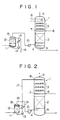
- the apparatus shown in Fig. 1 consists essentially of a C0 2 -removing tower 1 which comprises a lower packed section 2 for effecting an essential absorption of C0 2 of the combustion exhaust gas by an MEA aqueous solution; an upper contact section 3 constructed as a tray assembly for effecting depletion of MEA content in the gas after being treated in the lower packed section 2; a gas entrance 4 for the combustion exhaust gas supplied; an exit 5 of the final treated gas; a supply line 6 for the aqueous MEA solution; a first nozzle assembly 7 for spraying the MEA aqueous solution; a cooling means 8 for cooling the gas having been subjected to the C0 2 removal; a discharge outlet 9 for discharging the spent aqueous MEA solution containing the absorbed C0 2 from the tower 1; a feed blower 10 for boosting the combustion exhaust gas into the C0 2 -removing tower 1 from a primary scrubbing stage; a cooling section 12 for cooling the combustion exhaust gas supplied via a gas supply conduit 11 to effect conden
- the gas of which a part of the moisture content has been removed in the primary scrubbing stage as condensate, in the manner explained with reference to Fig. 4, is then supplied to the C0 2 -removing tower at the entrance 4 and is brought into contact in the lower packed section 2 with an aqueous MEA solution having a definite temperature and concentration supplied from the supply line 6 and sprayed from the first nozzle assembly 7 over the lower packed section 2 in counterflow to each other, whereby the C0 2 content in the combustion exhaust gas is removed by absorption by the aqueous MEA solution.
- the aqueous MEA solution containing thus the absorbed C0 2 is discharged out of the C0 2 -removing tower 1 via the discharge outlet 9 and is then fed to a regeneration tower, not shown, for regenerating the spent aqueous MEA solution, from which the regenerated aqueous MEA solution is returned to the C0 2 -removing tower 1 at the supply line 6.
- the amount of condensate formed in the upper contact section 3 by the cooling means 8 must be controlled by adjusting the flow rate of the coolant flowing inside the cooling means 8 so that the rate of condensate formation will correpond to the rate of total outgo of the moisture content from the system. Otherwise, the mass balance of water in the system composed of the C0 2 -removing tower 1 and the not shown spent absorbent regeneration tower connected therewith becomes destroyed, so that the concentration of the aqueous MEA solution supplied to the C0 2 -removing tower 1 at the entrance 6 will not be kept constant.
- the MEA vapor concentration in the rising stream of the C0 2 -denuded gas will be lowered by an approximate decimal order of two per unit theoretical plate in the upper contact section 3.
- the apparatus shown in Fig. 2 consists essentially of a C0 2 -removing tower 1, which comprises a lower packed section 2 for effecting an essential absorption of C0 2 of the combustion exhaust gas by an MEA aqueous solution; an upper contact section 3 for effecting depletion of MEA content in the gas after having being treated in the lower packed section 2; an entrance 4 for the combustion exhaust gas supplied; an exit 5 of the final treated gas; a supply line 6 for the aqueous MEA solution; a first nozzle assembly 7 for spraying the MEA aqueous solution; a condensate supply inlet 8 for supplying the condensate formed in the primary scrubbing stage via a condensate supply line 17 to the upper contact section 3; a discharge outlet 9 for discharging the spent aqueous MEA solution containing the absorbed C0 2 out of the tower 1; a feed blower 10 for boosting the combustion exhaust gas into the C0 2 -removing tower 1 from a primary scrubbing stage; a cooling section 12 for
- the combustion exhaust gas enters first the primary scrubbing stage via the inlet 11 and passes the cooling section 12 wherein it is cooled by contact with the circulated condensate cooled by the heat exchanger 14 and sprayed from the spray nozzle assembly 15, whereby the moisture content thereof is condensed and the condensate is accumulated in the bottom.
- the gas is then supplied to the C0 2 -removing tower 1 through a boosting blower 10 at the entrance 4, while the condensate accumulated in the bottom is supplied to the upper contact section 3 via the supply line 17 and the condensate supply inlet 8.
- the gas of which a part of the moisture content has been removed in the primary scrubbing stage as condensate is then supplied to the C0 2 -removing tower at the entrance 4 and is brought into contact in the lower packed section 2 with an aqueous MEA solution having a given temperature and concentration supplied from the supply line 6 and sprayed from the first nozzle assembly 7 over the lower packed section 2 in counterflow to each other, whereby the C0 2 content in the combustion exhaust gas is removed by absorption by the aqueous MEA solution.
- the aqueous MEA solution containing thus the absorbed C0 2 is discharged out of the C0 2 -removing tower 1 via the discharge outlet 9 and is then fed to a regeneration tower, not shown, for regenerating the spent aqueous MEA solution, from which the regenerated aqueous MEA solution is returned to the C0 2 -removing tower 1 via the supply line 6.
- the combustion exhaust gas which has been subjected to the removal of C0 2 in the lower packed section 2 and containing entrained therein the vapor of MEA flows up inside the tower 1 into the upper contact section 3 and is brought there into contact with the condensate supplied from the condensate supply inlet 8 in counterflow with each other.
- the amount of condensate supplied via the condensate supply inlet 8 must be controlled by adjusting the flow rate of the coolant flowing inside the cooling section 12 or the flow rate of the condensate passing the spray nozzle assembly so that the rate of condensate formation will correpond to the rate of total outgo of the moisture content from the system.
- FIG. 3 A further alternative embodiment of the present invention is shown in Fig. 3 in which only the essential elements are entered but accessory or subsidiary elements are not shown.
- the apparatus of this embodiment shown in Fig. 3 comprises a C0 2 -removing tower 41 comprising a lower packed section 42 for effecting an essential absorption of C0 2 of the combustion exhaust gas by an MEA aqueous solution, an upper contact section or tray assembly 43 for effecting depletion of MEA content in the gas after having been treated in the lower packed section 42, an entrance 44 for the combustion exhaust gas supplied, a gas exit 45 for the final treated gas, a supply line 46 for the aqueous MEA solution, a nozzle assembly 47 for spraying the MEA aqueous solution, a reflux water supply inlet 48 for supplying reflux water from a regeneration tower 28 and a further nozzle assembly 49; a primary scrubbing unit 20 for effecting primary scrubbing and cooling of the combustion exhaust gas comprising a nozzle assembly 21, a packed section 22, a circulation pump 23 and a make-up water supply line 24; a delivery pump 25 for draining the spent aqueous MEA solution containing the absorbed C0 2 , a heat exchange
- the combustion exhaust gas is boosted by the blower 39 into the primary scrubbing unit 20, in which it is brought into contact with the wetting cooling water 21 sprayed over the packed section 22 and is cooled and moistened.
- the so-cooled combustion exhaust gas is guided to the C0 2 -removing tower 41 via the gas entrance 44.
- the gas temperature at the entrance will reach usually about 50 - 80 °C , though some deviation may present in accordance with each specific condition. Since, however, it is unnecessary to cool the gas below such a level as above for treating it by the process according to the present invention, the cooling means 017 shown in Fig. 4 in the prior tehcnique mentioned previously can be dispensed with.
- the wetting cooling water after having been contacted with the combustion exhaust gas will be collected in the bottom of the primary scrubbing unit 20 and is used under circulation by the pump 23 through the nozzle assembly 21.
- the wetting cooling water will gradually be spent or lost by giving off into the hot gas, so that it is necessary to replenish the lost amount through the make-up water supply line 24.
- the combustion exhaust gas boosted by the blower 39 is brought into contact in the lower packed section 42 with the aqueous MEA solution having a given concentration sprayed from the nozzle assembly 47, as explained previously with reference to Fig. 4.
- the C0 2 content in the combustion exhaust gas will be absorbed by the aqueous MEA solution and is removed.
- the resulting C0 2 -denuded gas is then guided to the upper packed section 43.
- the aqueous MEA solution supplied to the C0 2 -removing tower 41 will absorb C0 2 and the absorption reaction gives off heat, whereby it is subjected to a heat elevation and reaches a temperature higher than the temperature at the inlet to the absorption tower 41.
- the so-warmed spent absorbent liquor is passed by the pump 25 to the heat exchanger 26, where it is further heated and then supplied to the spent adsorbent liquor regeneration tower 28.
- the regulation of the temperature of the aqueous MEA solution can be effected using the heat exchanger 26 or, if necessary, together with a cooling means 27 disposed optionally between the heat exchanger 26 and the aqueous MEA solution supply inlet 46.
- the temperature of the aqueous MEA solution supplied to the absorbing tower 41 will, in general, also become constant. In this manner, the temparature of the gas flowing within the exhaust path will not suffer from substantial temperature elevation even by the heat of the reaction.
- the gas flows within the gas exhaust path in the treating system at nearly the same temperature as that of the entrance 44, rising the tower 41 until it discharges out from the exit.
- the word "same temperature” with its strict meaning but should understand it as indicating a certain temperature range within which the mass balance of water in the system can be maintained.
- the overall mass balance with respect to water in the treatment system including the absorption tower 41 and other pertaining elements can be maintained.
- the temperature of the combustion exhaust gas supplied to the absorption tower 41 is in a relatively high range, such as 50 - 80 °C
- the cooling means 010 shown in Fig. 4 of the prior art can be dispensed with.
- any intolerable emission of MEA to the atmosphere can effectively be prevented by the process according to the present invention by using the reflux water fed from the spent absorbent liquor regeneration tower 28 in the absorption tower 41 as will be explained later on.
- the spent aqueous MEA solution is regenerated with heating by the regeneration reboiler 31 and the regenerated solution is then cooled by the heat exchenger 26 before it is returned to the absoption tower 41.
- the gaseous C0 2 separated from the aqueous MEA solution is brought into contact with the reflux water sprayed by the nozzle assembly 37, whereupon it is cooled by the regeneration tower reflux condenser 36 and is then separated from the water mist entained by the stream of C0 2 in the C0 2 separator 24.
- the thus separated C0 2 is guided to a C0 2 recovery stage via the line 35.
- a part of the reflux water is returned to the regeneration tower 28 by the reflux pump 33.
- the essential feature of this embodiment of the present invention resides in the technical measure of supplying a part of the reflux water to the absorption tower 41 through the regeneration tower reflux water supply line 38, the regenration tower reflux inlet 48 and the nozzle assebly 49.
- the MEA content in the C0 2 -denuded gas can be reduced to a level of almost zero.
- the reflux water having passed through the C0 2 separator 34 has a C0 2 content corresponding to the saturation concentration at that temperature. For example, if the temperature of the reflux water separated in the C0 2 separator 34 is approximately 40 ° C or so, the reflux water may have a C0 2 content of about 400 ppm.
- the C0 2 -denuded gas after having passed the lower packed section 12 in the absorption tower 41 may have a higher temperature in the range of 50 - 80 ° C and, thus, it may contain a relatively large amount of vaporized MEA corresponding to the partial pressure of MEA vapor at this temperature and a possible small amount of ammonia together with water steam and is forwarded upward to effect contact with the reflux water supplied from the regeneration tower 28 via the line 38 in counter current to each other.
- the reflux water supplied to the absorption tower 41 is brought into contact with the C0 2 -denuded gas to effect absorption of MEA and ammonia, whereupon it flows down the absorption tower 41 to the bottom thereof, where it is brought together with the spent aqueous MEA solution before they are sent to the regeneration tower 28.
- the reflux water to be supplied to the absorption tower 41 constitutes only a part of the total amount of the reflux water and, in addition, it is in any case returned to the regeneration tower 28, so that there occurs no destruction of mass balance of water in the total system.
- the residual content of MEA in the C0 2 -denuded gas will react with the dissolved C0 2 in the reflux water in the same manner as that occurring in the lower packed section 42 of the absorption tower 41. All the residual content of ammonia in the C0 2 -denuded combustion exhaust gas will be absorbed in water by being subjected to a reaction with C0 2 in the reflux water in accordance with either of the following equations (1) and (2) to form a carbonate salt and is dissolved in water.
- ammonium carbonated formed as above in particular NH4 HC03, are relatively stable in an aqueous solution, so that emission of ammonia into the atmosphere may in some degree be suppressed by being removed from the C0 2 -denuded gas in the form of these salts. If the C0 2 removal teatment is continued for a prolonged period of time as such, these ammonium salts will be accumulated inside the system and may be decomposed in the regeneration step into ammonia, so that a complete prevention of emission of ammonia into the atmosphere is difficult.
- wet cooling is employed for the cooling of combustion exhaust gas.
- this may not always necessarily be employed, but other cooling means, such as shown in Fig. 4 may also be employed.
- the mass balance of water in the entire combustion gas treatment system can relaibly be maintained by the adjustment of the temperature of aqueous MEA solution supplied to the absorption tower in such a manner that the temperatures of the C0 2 -denuded gas at the entrance and the exit will be substantially identical.
Landscapes
- Chemical & Material Sciences (AREA)
- Engineering & Computer Science (AREA)
- Analytical Chemistry (AREA)
- General Chemical & Material Sciences (AREA)
- Oil, Petroleum & Natural Gas (AREA)
- Chemical Kinetics & Catalysis (AREA)
- Health & Medical Sciences (AREA)
- Biomedical Technology (AREA)
- Environmental & Geological Engineering (AREA)
- Treating Waste Gases (AREA)
- Gas Separation By Absorption (AREA)
Description
- The present invention relates to a process for removing carbon dioxide from combustion exhast gas, in particular, that uses an alkanolamine as the absorbent, and to an apparatus to be employed therefor.
- In recent years, the so-called "greenhouse effect" due to increasing concentration of C02 in the atmosphere has come to the forefront as an essential causal factor for the phenomenen of global climatic warmth. Thus, it has become an international urgent theme to provide an effective countermeasure therefor, in order to realize protection of the global environmental condition. C02 comes out of quite many origins widespread over every field of human activity that uses combustion of fossile fuels. It is therefore an international trend to prescribe a more strict limitation on the amount of emission of C02 into the atmosphere. Under these circumstances, there have been developing intensive researches, in particular, in power plants, which consume large amounts of consumption of fossile fuel, as to an effective technical measure of recovering C02 by bringing the combustion exhaust gas from the boiler plant thereof into contact with an absorbent, such as an aqueous solution of an alkanolamine etc., and as to a practical way for effecting storage of the recovered C02 without exhausting it into the atmosphere.
- Here, there may be employed as the absorbent for C02, for example, aqueous solutions of alkanolamines, such as monoethanolamine, diethanolamine, triethanolamine, methyl diethanolamine, diisopropanolamine and diglycolamine as well as mixtures of these amines. Among them, usually an aqueous solution of monoethanolamine (abbreviated hereinafter as MEA) is employed with preference in a form of anaqueous solution.
- One typical example of an apparatus for effecting the conventional process for C02 removal using an aqueous solution of monoethanolamine (MEA) as the absorbent is explained now with reference to Fig. 4 appended herewith.
- The apparatus shown in Fig. 4, which may be employed primarily for removing C02 from the combustion exhaust gas from a fire source using a hydrogen-rich fuel, such as liquefied natural gas (LNG), consists essentially of a C02-removing tower 01, which comprises a lower packed
section 02 for effecting an essential absorption of C02 from the combustion exhaust gas by an MEA aqueous solution; an upper packedsection 03 for effecting depletion of MEA content in the gas after having been treated in the lower packedsection 02; anentrance 04 for the combustion exhaust gas supplied; anexit 05 of the final treated gas; asupply line 06 for the aqueous MEA solution; afirst nozzle assembly 07 for spraying the MEA aqueous solution; acondensate accumulating tray 08, which may eventually be dispensed with, for receiving the condensate formed in the upper packedsection 03; acirculation pump 09 for maintaining circulation of the condensate within the upper packed section; a heat exchanger 010 for effecting cooling of the condensate; asecond nozzle assembly 011 for spraying the circulating condensate over the upper packedsection 03; adischarge outlet 012 for discharging the spent aqueous MEA solution containing the absorbed C02 out of the tower 01; and afeed blower 013 for boosting the combustion exhaust gas from a primary scrubbing stage into the absorption tower 01 via theentrance 04. The primary scrubbing stage consists essentially of a circulation system comprising acooling section 015 for cooling the combustion exhaust gas supplied via agas supply conduit 014 to effect condensing of the moisture content in the exhaust gas; acirculation pump 016 for circulating the condensate; aheat exchanger 017 for effecting heat exchange to cool the circulating condensate; and anozzle assembly 018 for spraying the cooled condensate over thecooling section 015 to effect cooling and primary scrubbing of the combustion exhaust gas, and is provided with acondensate extracting line 019 for extracting the excessive amount of condensate out of the system. - The combustion exhaust gas from, for example, the boiler plant of a power station, having in general a temperature of 100 - 150 ° C , is supplied first to the primary scrubbing stage, in which it is cooled in the
cooling section 015 while forming a condensate which accumulates in its bottom and is employed as the cooling and scrubbing liquor sprayed from thenozzle assembly 018 under circulation by thecirculation pump 016 with cooling by theheat exchanger 017, wherein a part of the condensate is continuously extracted out of the system via theextraction line 019. The combustion exhaust gas after having passed the primary scrubbing stage is supplied to the C02-removing tower 01 at theentrance 014 via abooster blower 013. The combustion exhaust gas supplied to the C02-removing tower is brought into contact with an aqueous MEA solution having a definite temperature and concentration supplied from thesupply line 06 and sprayed from thefirst nozzle assembly 07 over the lower packedsection 02 in counterflow to the rising gas, whereby the C02 content in the combustion exhaust gas is removed by absorption by the aqueous MEA solution. The aqueous MEA solution containing thus the absorbed C02 is discharged out of the C02- removing tower 01 via theoutlet 012 and is then fed to a regeneration tower, not shown, for regenerating the spent aqueous MEA solution, from which the regenerated aqueous MEA solution is returned to the C02- removing tower 01 at thesupply line 06. - On the other hand, the combustion exhaust gas which has been subjected to the C02 removal in the lower packed
section 02 flows up passing through a layer of the condensate accumulated on thecondensate accumulation tray 08 into the upper packedsection 03. The temperature of the gas entering the upper packedsection 03 has been elevated by the exothermal reaction of absorption of C02 with MEA effected in the lower packedsection 02, so that the gas entering the upper packedsection 03 has a higher content of vaporized MEA corresponding to the saturation concentration thereof in the gas at such elevated temperature. Therfore, the combustion exhaust gas which has thus been subjected to the C02 removal should not be exhausted out to the atmosphere as such in consideration of the possible pollution of the atmosphere and the loss of MEA. Thus, the combustion exhaust gas having been denuded of its C02 content in the lower packedsection 02 is then treated in the upper packedsection 03 in such a manner that a suitable amount of the condensate formed and separated in the upper packed section is sprayed over the upper packedsection 03 through the second nozzle assemply 011 under circulation thereof by thecirculation pump 09 through a cooling means (the heat exchanger 010) so as to effect contact of the cooled condensate with the rising gas in counterflow to each other to lower the temperature of the gas, while at the same time to condense the water vapor together with MEA to decrease the MEA concentration in the gas, in order to prevent discharge of any harmful amount of MEA into the atmosphere. - The above example of the prior technique shown in Fig. 4 is employed primarily for firing stations using a fuel containing a substantial amount of hydrogen, such as LNG, capable of forming a sufficient amount of water vapor originated from the combustion of such a hydrogen-rich fuel for permitting to serve for use as the water source for building up the aqueous MEA solution and for use for cooling the combustion exhaust gas. The condensate thus formed is exhausted from the
line 019 as excess water. - Alternatively, there has been proposed also a system in which the cooling of the combustion exhaust gas is effected using an externally supplied amount of water, which may be employed principally for boiler plants burning a fuel having high content of carbon, such as coal, heavy oil or so on. Here, it is, in general, unnecessary to provide the
heat exchanger 017, as will be explained later on, but is only necessary to bring the combustion exhaust gas into contact with water held in circulation within the system to effect cooling of the combustion exhaust gas by the latent heat of vaporization of water. Here, an amount of fresh water should be supplied from outside, in order to replenish the amount of water lost gradually during the operation by giving off to the atmosphere by evaporation. - Though the prior art explained as above with reference to the appended Fig. 4 may be useful as much for a specific field of applications, it possesses a disadvantage that the level of leakage of the absorbent, i.e. MEA, from the C02-removing tower into the atmosphere is still high , causing thus corresponding degree of atmospheric pollution and a larger loss of the expensive absorbent. In addition, it was recognized that ammonia was detected, though in a quite small amount, in the gas discharged out to the atmosphere from the
exit 05 of the C02-removing tower 01 of the prior art apparatus. This ammonia may assumably be derived from a partial decomposition of MEA in the treatment system. It may also be possible for the reason therefor that the fuel would have had originally a residual ammonia content added in order to decrease the NOX level in the combustion exhaust gas. In any case, an occurrence of ammonia, though in a trifling amount, may be a further origin of unpleasant smell and bring about an emvironmental pollution when emitted to the atmosphere, so that it has to be removed from the gas before it is discharged out to the atmosphere. Here, it was a problem that the level of ammonia is quite low and, therefore , it has to be removed at a sufficient efficiency. - Starting from the prior technique of removal of C02 in the combustion exhaust gas from fire sources explained above, the present invention has as its primary object a theme to provide a process and an apparatus for removing C02 in the combustion exhaust gas from fire sources, which can permit a considerable lowering of the amount of loss of the alkanolamine employed for the absorbent and thus a substantial reduction of the atmospheric pollution therefrom as compared with the state of the art.
- The inventors have found in their sound researches carried out as for the technical theme set forth above that it was effective for the object of the present invention to bring reflux water from a spent absorbent liquor regeneration tower into contact, within the C02-removing tower, with the combustion exhaust gas having been subjected to the C02 removal, and has completed the present invention.
- The essential features of the present invention are as given below:
- A) A process for removing C02 from a combustion exhaust gas, said process comprising the steps of: bringing a combustion exhaust gas into counterflow contact with an aqueous alkanolamine solution for removal of C02 from said exhaust gas; maintaining said exhaust gas having been subjected to the removal of C02 at a temperature higher than the saturation point of moisture in the exhaust gas; cooling and condensing such an amount of the moisture in said exhaust gas that corresponds to the amount of water brought out in accompaniment with the treated exhaust gas discharged; and bringing the so-formed condensate into counterflow contact with said exhaust gas having been subjected to the removal of C02.
- An apparatus for carrying out the process comprising: a first contact section for the contact between a combustion exhaust gas and an alkanolamine solution for removal of C02 from said exhaust gas; a cooling means disposed downstream in the flow of the combustion exhaust gas from the first contact section; and a second contact section for contact between the condensate and said exhaust gas. B) A process for removing C02 from a combustion exhaust gas, said process comprising the steps of: cooling the combustion exhaust gas before C02 removal; bringing the cooled exhaust gas into counterflow contact with an alkanolamine solution for removal of C02 from the exhaust gas by absorption into the alkanolamine solution; and supplying condensate water formed at said cooling step and bringing the exhaust gas having been subjected to the C02 removal into counterflow contact with the supplied condensate water, wherein an amount of the supplied condensate water corresponds to an amount of water brought out of a C02 removal system in accompaniment with the exhaust gas discharged after said C02 removal.
- An apparatus for carrying out the process comprising a cooling section for cooling a combustion exhaust gas before C02 removal, a C02 removingtower, and a supply means for supplying condensate water produced at the cooling section to said C02 removing tower, wherein said C02 removing tower includes a first contact section for effecting the counterflow contact of the exhaust gas with an alkanolamine solution, and a second contact section disposed downstream of the exhaust gas from said first contact section for effecting the counterflow contact of the exhaust gas with the condensate water, and wherein said supply means supplies the condensate water to said second contact section. C) A process for removing C02 from a combustion exhaust gas, said process comprising the steps of: bringing a combustion exhaust gas into counterflow contact with an alkanolamine solution for removal of C02 from the exhaust gas by absorption into the alkanolamine solution; bringing the exhaust gas having been subjected to the C02 removal into counterflow contact with reflux water produced at a regenerating step of regenerating the spent alkanolamine solution; and adjusting the temperature of the alkanolamine solution to be supplied to said C02 removing tower in such a manner that the temperature of the exhaust gas at the entrance of the C02 removing tower and that at the exit of the C02 removing tower are substantially identical.
- An apparatus for carrying out the process comprising a C02 removing tower for removing C02 from a combustion exhaust gas by absorption into an alkanolamine solution, a regenerating tower for regenerating the spent alkanolamine solution, and means for supplying the reflux water from said regeneration tower to said C02 removing tower; wherein said C02 removing tower includes a first contact section for effecting the counterflow contact of the exhaust gas with the alkanolamine solution, and a second contact section for effecting the counterflow contact of the exhaust gas with the reflux water.
-
- Fig. 1 shows a schematic illustration of an embodiment of the apparatus according to the present invention.
- Fig. 2 is a schematic illustration of another embodiment of the apparatus according to the present invention.
- Fig. 3 is a schematic illustration of a still another embodiment of the apparatus according to the present invention.
- Fig. 4 shows a schematic illustration of a typical embodiment of the conventional apparatus of the stand of the technique.
- Below, the present invention is explained in detail with reference to Figs. 1 to 3 of the appended drawings which show each an embodiment of the present invention in a schematic illustration.
- The apparatus shown in Fig. 1 consists essentially of a C02-removing tower 1 which comprises a lower packed
section 2 for effecting an essential absorption of C02 of the combustion exhaust gas by an MEA aqueous solution; anupper contact section 3 constructed as a tray assembly for effecting depletion of MEA content in the gas after being treated in the lower packedsection 2; agas entrance 4 for the combustion exhaust gas supplied; an exit 5 of the final treated gas; asupply line 6 for the aqueous MEA solution; afirst nozzle assembly 7 for spraying the MEA aqueous solution; a cooling means 8 for cooling the gas having been subjected to the C02 removal; adischarge outlet 9 for discharging the spent aqueous MEA solution containing the absorbed C02 from the tower 1; afeed blower 10 for boosting the combustion exhaust gas into the C02-removing tower 1 from a primary scrubbing stage; acooling section 12 for cooling the combustion exhaust gas supplied via agas supply conduit 11 to effect condensing of the moisture content in the combustion exhaust gas; acirculation pump 13 for circulating the condensate; aheat exchanger 14 for effecting heat exchange to cool the circulating condensate; anozzle assembly 15 for spraying the cooled condensate over thecooling section 12 to effect cooling and primary scrubbing of the combustion exhaust gas; and acondensate extracting line 16 for extracting the excessive amount of the condensate out of the system. - The gas of which a part of the moisture content has been removed in the primary scrubbing stage as condensate, in the manner explained with reference to Fig. 4, is then supplied to the C02-removing tower at the
entrance 4 and is brought into contact in the lower packedsection 2 with an aqueous MEA solution having a definite temperature and concentration supplied from thesupply line 6 and sprayed from thefirst nozzle assembly 7 over the lower packedsection 2 in counterflow to each other, whereby the C02 content in the combustion exhaust gas is removed by absorption by the aqueous MEA solution. The aqueous MEA solution containing thus the absorbed C02 is discharged out of the C02-removing tower 1 via thedischarge outlet 9 and is then fed to a regeneration tower, not shown, for regenerating the spent aqueous MEA solution, from which the regenerated aqueous MEA solution is returned to the C02-removing tower 1 at thesupply line 6. - The combustion exhaust gas which has been subjected to the removal of C02 in the lower packed
section 2 and having entrained therein the vapor of MEA flows up inside the tower 1 into theupper contact section 3. Here, the amount of condensate formed in theupper contact section 3 by the cooling means 8 must be controlled by adjusting the flow rate of the coolant flowing inside the cooling means 8 so that the rate of condensate formation will correpond to the rate of total outgo of the moisture content from the system. Otherwise, the mass balance of water in the system composed of the C02-removing tower 1 and the not shown spent absorbent regeneration tower connected therewith becomes destroyed, so that the concentration of the aqueous MEA solution supplied to the C02-removing tower 1 at theentrance 6 will not be kept constant. - By the absorption reaction effected on contact of the rising stream of the C02-denuded gas containing now vapor of MEA with the falling condensate formed by cooling on the cooling means 8 in the
upper contact section 3, the MEA vapor concentration in the rising stream of the C02-denuded gas will be lowered by an approximate decimal order of two per unit theoretical plate in theupper contact section 3. By selecting adequate number of actual trays, it is possible to adjust the amount of MEA brought out of the system in accompaniment with the discharged treated gas via the exit 5 to a level of nearly zero. - Now, the description will be directed to the second embodiment according to the present invention shown in Fig. 2.
- The apparatus shown in Fig. 2 consists essentially of a C02-removing tower 1, which comprises a lower packed
section 2 for effecting an essential absorption of C02 of the combustion exhaust gas by an MEA aqueous solution; anupper contact section 3 for effecting depletion of MEA content in the gas after having being treated in the lower packedsection 2; anentrance 4 for the combustion exhaust gas supplied; an exit 5 of the final treated gas; asupply line 6 for the aqueous MEA solution; afirst nozzle assembly 7 for spraying the MEA aqueous solution; acondensate supply inlet 8 for supplying the condensate formed in the primary scrubbing stage via acondensate supply line 17 to theupper contact section 3; adischarge outlet 9 for discharging the spent aqueous MEA solution containing the absorbed C02 out of the tower 1; afeed blower 10 for boosting the combustion exhaust gas into the C02-removing tower 1 from a primary scrubbing stage; acooling section 12 for cooling the combustion exhaust gas supplied via agas supply inlet 11 to effect condensing of the moisture content in the exhaust gas; acirculation pump 13 for circulating the condensate; aheat exchanger 14 for effecting heat exchange to cool the circulating condensate; anozzle assembly 15 for spraying the cooled condensate over thecooling section 12 to effect cooling and primary scrubbing of the combustion exhaust gas; and a combustion exhaustgas supply line 16 for supplying the combustion exhaust gas from the primary scrubbing stage. The combustion exhaust gas enters first the primary scrubbing stage via theinlet 11 and passes thecooling section 12 wherein it is cooled by contact with the circulated condensate cooled by theheat exchanger 14 and sprayed from thespray nozzle assembly 15, whereby the moisture content thereof is condensed and the condensate is accumulated in the bottom. The gas is then supplied to the C02-removing tower 1 through aboosting blower 10 at theentrance 4, while the condensate accumulated in the bottom is supplied to theupper contact section 3 via thesupply line 17 and thecondensate supply inlet 8. - The gas of which a part of the moisture content has been removed in the primary scrubbing stage as condensate is then supplied to the C02-removing tower at the
entrance 4 and is brought into contact in the lower packedsection 2 with an aqueous MEA solution having a given temperature and concentration supplied from thesupply line 6 and sprayed from thefirst nozzle assembly 7 over the lower packedsection 2 in counterflow to each other, whereby the C02 content in the combustion exhaust gas is removed by absorption by the aqueous MEA solution. The aqueous MEA solution containing thus the absorbed C02 is discharged out of the C02-removing tower 1 via thedischarge outlet 9 and is then fed to a regeneration tower, not shown, for regenerating the spent aqueous MEA solution, from which the regenerated aqueous MEA solution is returned to the C02-removing tower 1 via thesupply line 6. - The combustion exhaust gas which has been subjected to the removal of C02 in the lower packed
section 2 and containing entrained therein the vapor of MEA flows up inside the tower 1 into theupper contact section 3 and is brought there into contact with the condensate supplied from thecondensate supply inlet 8 in counterflow with each other. Here, the amount of condensate supplied via thecondensate supply inlet 8 must be controlled by adjusting the flow rate of the coolant flowing inside thecooling section 12 or the flow rate of the condensate passing the spray nozzle assembly so that the rate of condensate formation will correpond to the rate of total outgo of the moisture content from the system. Otherwise, the mass balance of water in the system composed of the C02-removing tower 1 and the not shown spent absorbent regeneration tower connected therewith becomes destroyed, so that the concentration of the aqueous MEA solution supplied to the C02-removing tower 1 at theentrance 6 will not be kept constant. - This embodiment of the present invention can afford to realize the same advantageous effects as that described with reference to Fig. 1.
- As seen from the description of the preferred embodiments set forth above, it is possible by the process and the apparatus according to the present invention to attain a condition in which the amount of the alkanolamine absorbent lost to the atmosphere becomes close to zero, whereby it is possible to avoid the possible atmospheric pollution due to the leakage of the absorbent and also attain a marked economization of the energy consumption for the circulation of fluids as compared with the conventional technique such as shown in Fig. 4, with simultaneous omission of the heat exchanger to be installed therewith.
- Below, each feature of the above embodiments shown in Figs. 1 and 2 is summarized in Tables 1 and 2 in comparison with that of the conventional technique explained by Fig. 4, in order to visualize the technical advantages realized by the present invention.


- A further alternative embodiment of the present invention is shown in Fig. 3 in which only the essential elements are entered but accessory or subsidiary elements are not shown.
- The apparatus of this embodiment shown in Fig. 3 comprises a C02-removing tower 41 comprising a lower packed section 42 for effecting an essential absorption of C02 of the combustion exhaust gas by an MEA aqueous solution, an upper contact section or tray assembly 43 for effecting depletion of MEA content in the gas after having been treated in the lower packed section 42, an entrance 44 for the combustion exhaust gas supplied, a gas exit 45 for the final treated gas, a supply line 46 for the aqueous MEA solution, a nozzle assembly 47 for spraying the MEA aqueous solution, a reflux water supply inlet 48 for supplying reflux water from a regeneration tower 28 and a further nozzle assembly 49; a primary scrubbing unit 20 for effecting primary scrubbing and cooling of the combustion exhaust gas comprising a nozzle assembly 21, a packed section 22, a circulation pump 23 and a make-up water supply line 24; a delivery pump 25 for draining the spent aqueous MEA solution containing the absorbed C02, a heat exchanger 26 for effecting heat exchange to recover the heat of the regeneration tower bottom; a cooling means 27 for cooling the absorbent liquor before being sprayed over the lower packed section; a spent absorbent liquor regeneration tower 28 comprising a nozzle assembly 29, a lower packed section 30, a regeneration reboiler 31, an upper packed section 32, a reflux water return pump 33, a C02 separator 34,a transfer line 35 for transferring the recovered C02, a reflux condenser 36 for cooling the overhead of the regeneration tower 28, and a nozzle assembly 37 for spraying the reflux water over the upper packed section 32 of the regeneration tower 28; a reflux water supply line 38 from the regeration unit; and a combustion exhaust gas boosting blower 39.
- The combustion exhaust gas is boosted by the
blower 39 into theprimary scrubbing unit 20, in which it is brought into contact with the wettingcooling water 21 sprayed over the packedsection 22 and is cooled and moistened. The so-cooled combustion exhaust gas is guided to the C02-removingtower 41 via thegas entrance 44. The gas temperature at the entrance will reach usually about 50 - 80 °C , though some deviation may present in accordance with each specific condition. Since, however, it is unnecessary to cool the gas below such a level as above for treating it by the process according to the present invention, the cooling means 017 shown in Fig. 4 in the prior tehcnique mentioned previously can be dispensed with. - The wetting cooling water after having been contacted with the combustion exhaust gas will be collected in the bottom of the
primary scrubbing unit 20 and is used under circulation by thepump 23 through thenozzle assembly 21. The wetting cooling water will gradually be spent or lost by giving off into the hot gas, so that it is necessary to replenish the lost amount through the make-upwater supply line 24. - The combustion exhaust gas boosted by the
blower 39 is brought into contact in the lower packedsection 42 with the aqueous MEA solution having a given concentration sprayed from thenozzle assembly 47, as explained previously with reference to Fig. 4. The C02 content in the combustion exhaust gas will be absorbed by the aqueous MEA solution and is removed. The resulting C02-denuded gas is then guided to the upper packedsection 43. The aqueous MEA solution supplied to the C02-removingtower 41 will absorb C02 and the absorption reaction gives off heat, whereby it is subjected to a heat elevation and reaches a temperature higher than the temperature at the inlet to theabsorption tower 41. The so-warmed spent absorbent liquor is passed by thepump 25 to theheat exchanger 26, where it is further heated and then supplied to the spent adsorbentliquor regeneration tower 28. - In this embodiment, most of the reaction heat due to the absorption of C02 is carried away from the C02-removing
tower 41 by the aqueous MEA solution sent to theregeneration tower 28, by adjusting the temperature of the aqueous MEA solution supplied to theabsorption tower 41. - The regulation of the temperature of the aqueous MEA solution can be effected using the
heat exchanger 26 or, if necessary, together with a cooling means 27 disposed optionally between theheat exchanger 26 and the aqueous MEAsolution supply inlet 46. After a steady state of the entire treating system has been reached, the temperature of the aqueous MEA solution supplied to the absorbingtower 41 will, in general, also become constant. In this manner, the temparature of the gas flowing within the exhaust path will not suffer from substantial temperature elevation even by the heat of the reaction. Thus, the gas flows within the gas exhaust path in the treating system at nearly the same temperature as that of theentrance 44, rising thetower 41 until it discharges out from the exit. Here, one should not understand the word "same temperature" with its strict meaning but should understand it as indicating a certain temperature range within which the mass balance of water in the system can be maintained. - By adjusting the temperature of the aqueous MEA solution supplied from the aqueous MEA
solution supply line 46 so that the temperatures of the gas at the gas entrance and the gas exit will be the same, the overall mass balance with respect to water in the treatment system including theabsorption tower 41 and other pertaining elements can be maintained. Thus, even though the temperature of the combustion exhaust gas supplied to theabsorption tower 41 is in a relatively high range, such as 50 - 80 °C , the cooling means 010 shown in Fig. 4 of the prior art can be dispensed with. Even if, on the other hand, the temperature of the treated gas exhausted from theabsorption tower 41 is at a higher level, any intolerable emission of MEA to the atmosphere can effectively be prevented by the process according to the present invention by using the reflux water fed from the spent absorbentliquor regeneration tower 28 in theabsorption tower 41 as will be explained later on. - In the spent absorbent
liqor regeneration tower 28, the spent aqueous MEA solution is regenerated with heating by theregeneration reboiler 31 and the regenerated solution is then cooled by theheat exchenger 26 before it is returned to theabsoption tower 41. In the upper part of theregeneration tower 28, the gaseous C02 separated from the aqueous MEA solution is brought into contact with the reflux water sprayed by thenozzle assembly 37, whereupon it is cooled by the regenerationtower reflux condenser 36 and is then separated from the water mist entained by the stream of C02 in the C02 separator 24. The thus separated C02 is guided to a C02 recovery stage via theline 35. A part of the reflux water is returned to theregeneration tower 28 by thereflux pump 33. - The essential feature of this embodiment of the present invention resides in the technical measure of supplying a part of the reflux water to the
absorption tower 41 through the regeneration tower refluxwater supply line 38, the regenrationtower reflux inlet 48 and thenozzle assebly 49. By bringing this returned portion of reflux water in the upper packed section or thetray assembly 30 into contact with the C02- denuded gas having a residual content of MEA vapor, the MEA content in the C02-denuded gas can be reduced to a level of almost zero. In the reflux water having passed through the C02 separator 34 has a C02 content corresponding to the saturation concentration at that temperature. For example, if the temperature of the reflux water separated in the C02 separator 34 is approximately 40 ° C or so, the reflux water may have a C02 content of about 400 ppm. - On the other hand, the C02-denuded gas after having passed the lower packed
section 12 in theabsorption tower 41 may have a higher temperature in the range of 50 - 80 ° C and, thus, it may contain a relatively large amount of vaporized MEA corresponding to the partial pressure of MEA vapor at this temperature and a possible small amount of ammonia together with water steam and is forwarded upward to effect contact with the reflux water supplied from theregeneration tower 28 via theline 38 in counter current to each other. Since ammonia and MEA are weakly alkaline and C02 dissolved in water is weakly acidic, the alkaline absorbent residue will be captured quite easily as compared with the prior art using water for scavenging the residual content of these alkaline absorbent, and the leakage of these substances to the atmosphere can effectively prevented. The reflux water supplied to theabsorption tower 41 is brought into contact with the C02-denuded gas to effect absorption of MEA and ammonia, whereupon it flows down theabsorption tower 41 to the bottom thereof, where it is brought together with the spent aqueous MEA solution before they are sent to theregeneration tower 28. The reflux water to be supplied to theabsorption tower 41 constitutes only a part of the total amount of the reflux water and, in addition, it is in any case returned to theregeneration tower 28, so that there occurs no destruction of mass balance of water in the total system. - By the way, the residual content of MEA in the C02-denuded gas will react with the dissolved C02 in the reflux water in the same manner as that occurring in the lower packed
section 42 of theabsorption tower 41. All the residual content of ammonia in the C02-denuded combustion exhaust gas will be absorbed in water by being subjected to a reaction with C02 in the reflux water in accordance with either of the following equations (1) and (2)

- The ammonium carbonated formed as above, in particular NH4 HC03, are relatively stable in an aqueous solution, so that emission of ammonia into the atmosphere may in some degree be suppressed by being removed from the C02-denuded gas in the form of these salts. If the C02 removal teatment is continued for a prolonged period of time as such, these ammonium salts will be accumulated inside the system and may be decomposed in the regeneration step into ammonia, so that a complete prevention of emission of ammonia into the atmosphere is difficult.
- In the embodiment of Fig. 3, wet cooling is employed for the cooling of combustion exhaust gas. However, this may not always necessarily be employed, but other cooling means, such as shown in Fig. 4 may also be employed. According to this embodiment of the present invention, however, it is possible to prevent effectively the leakage of residual MEA to the atmosphere by employing the reflux water from the regeneration tower containing dissolved C02, even though the residual content of MEA in the C02-denuded gas is relative high due to higher temperature of the gas. Therefore, the employment of the cooling means 010 shown in Fig. 4 of the prior art is now unnecessary, whereby a further economical advantage is relized.
- Below, each particular feature of the above embodiment of the present invention as shown in Fig. 3 and that for the prior technique of Fig. 4 are summarized in Table 3, in order to visualize the advantageous effects realized by the present invention.

- As described in detail above, it is now made possible to prevent emission of residual alkanolamine contained in the treated gas, which has been subjected to C02 removal, quite effectively, since a part of the reflux water from the spent absorbent solution regeneration tower is employed for scavenging the residual alkanolamine in the treated gas. At the same time, a suppression of ammonia emission into the atmosphere together with the treated gas can be suppressed in some degree. It is also made possible to dispense with installation of circulation of water at the overhead of the C02 absorption tower which has been necessary in the prior art, in addition, the use of a cooling means therefor is now become unnecessary. The mass balance of water in the entire combustion gas treatment system can relaibly be maintained by the adjustment of the temperature of aqueous MEA solution supplied to the absorption tower in such a manner that the temperatures of the C02-denuded gas at the entrance and the exit will be substantially identical.
Claims (6)
Applications Claiming Priority (6)
| Application Number | Priority Date | Filing Date | Title |
|---|---|---|---|
| JP4185491 | 1991-03-07 | ||
| JP41854/91 | 1991-03-07 | ||
| JP3041854A JP2539103B2 (en) | 1991-03-07 | 1991-03-07 | Device and method for decarbonizing flue gas |
| JP4006469A JP2786560B2 (en) | 1992-01-17 | 1992-01-17 | Apparatus and method for removing carbon dioxide from flue gas |
| JP6469/92 | 1992-01-17 | ||
| JP646992 | 1992-01-17 |
Publications (3)
| Publication Number | Publication Date |
|---|---|
| EP0502596A1 EP0502596A1 (en) | 1992-09-09 |
| EP0502596B1 true EP0502596B1 (en) | 1995-12-20 |
| EP0502596B2 EP0502596B2 (en) | 1999-08-25 |
Family
ID=26340617
Family Applications (1)
| Application Number | Title | Priority Date | Filing Date |
|---|---|---|---|
| EP92250053A Expired - Lifetime EP0502596B2 (en) | 1991-03-07 | 1992-03-06 | Apparatus and process for removing carbon dioxide from combustion exhaust gas |
Country Status (5)
| Country | Link |
|---|---|
| US (1) | US5318758A (en) |
| EP (1) | EP0502596B2 (en) |
| KR (1) | KR950006512B1 (en) |
| DE (1) | DE69206846T3 (en) |
| DK (1) | DK0502596T4 (en) |
Cited By (2)
| Publication number | Priority date | Publication date | Assignee | Title |
|---|---|---|---|---|
| CN103608087A (en) * | 2011-02-02 | 2014-02-26 | 阿尔斯通技术有限公司 | Method for reducing regeneration energy |
| CN105408005A (en) * | 2013-07-25 | 2016-03-16 | 西门子公司 | System for separating out volatile degradation products, and method for operating the system |
Families Citing this family (99)
| Publication number | Priority date | Publication date | Assignee | Title |
|---|---|---|---|---|
| DE69233766D1 (en) * | 1991-10-09 | 2009-09-03 | Kansai Electric Power Co | Recovery of carbon dioxide from combustion exhaust gas |
| US5378442A (en) * | 1992-01-17 | 1995-01-03 | The Kansai Electric Power Co., Inc. | Method for treating combustion exhaust gas |
| NO180520C (en) * | 1994-02-15 | 1997-05-07 | Kvaerner Asa | Method of Removing Carbon Dioxide from Combustion Gases |
| JPH09262432A (en) * | 1996-03-29 | 1997-10-07 | Kansai Electric Power Co Inc:The | Method for recovering basic amine compound in decarbonation tower exhaust gas |
| US6019818A (en) * | 1996-09-27 | 2000-02-01 | G.F.K. Consulting, Ltd. | Combination quenching and scrubbing process and apparatus therefor |
| JP4523691B2 (en) * | 2000-03-10 | 2010-08-11 | 三菱重工業株式会社 | Method and apparatus for controlling absorbent of decarbonation equipment |
| NO319666B1 (en) * | 2000-06-16 | 2005-09-05 | Enpro As | Process for removing salt from saline water and its use |
| US6387159B1 (en) * | 2000-06-26 | 2002-05-14 | Engelhard Corporation | Claus feed gas hydrocarbon removal |
| JP3969949B2 (en) * | 2000-10-25 | 2007-09-05 | 関西電力株式会社 | Amine recovery method and apparatus, and decarbonation gas apparatus provided with the same |
| US6500241B2 (en) * | 2000-12-19 | 2002-12-31 | Fluor Corporation | Hydrogen and carbon dioxide coproduction |
| EP1432495A1 (en) * | 2001-10-02 | 2004-06-30 | Union Engineering A/S | Method and device for recovery of thermal from an exothermic carbon dioxide absorption process |
| US6508863B1 (en) | 2001-10-11 | 2003-01-21 | Engelhard Corporation | Claus feed gas hydrocarbon removal |
| DE10155791C1 (en) * | 2001-11-14 | 2003-07-17 | Starck H C Gmbh | Process for the electrochemical digestion of superalloys |
| JP3814206B2 (en) * | 2002-01-31 | 2006-08-23 | 三菱重工業株式会社 | Waste heat utilization method of carbon dioxide recovery process |
| JP4138399B2 (en) * | 2002-08-21 | 2008-08-27 | 三菱重工業株式会社 | Method for producing liquefied natural gas |
| US7252703B2 (en) * | 2003-06-30 | 2007-08-07 | Honeywell International, Inc. | Direct contact liquid air contaminant control system |
| CN1826165B (en) * | 2003-07-22 | 2010-12-08 | 陶氏环球技术公司 | Regeneration of treatment fluids containing acid gases |
| CA2574633C (en) * | 2004-08-06 | 2010-08-10 | Eig, Inc. | Ultra cleaning of combustion gas including the removal of co2 |
| US20060289003A1 (en) * | 2004-08-20 | 2006-12-28 | Lackner Klaus S | Laminar scrubber apparatus for capturing carbon dioxide from air and methods of use |
| US20060051274A1 (en) * | 2004-08-23 | 2006-03-09 | Wright Allen B | Removal of carbon dioxide from air |
| US7655069B2 (en) * | 2005-02-02 | 2010-02-02 | Global Research Technologies, Llc | Removal of carbon dioxide from air |
| WO2007018558A2 (en) * | 2005-07-20 | 2007-02-15 | The Trustees Of Columbia University In The City Of New York | Electrochemical recovery of carbon dioxide from alkaline solvents |
| US9266051B2 (en) | 2005-07-28 | 2016-02-23 | Carbon Sink, Inc. | Removal of carbon dioxide from air |
| CN102160957A (en) * | 2005-07-28 | 2011-08-24 | 乞力马扎罗能量公司 | Removal of carbon dioxide from air |
| US7993432B2 (en) | 2006-03-08 | 2011-08-09 | Kilimanjaro Energy, Inc. | Air collector with functionalized ion exchange membrane for capturing ambient CO2 |
| WO2008042919A2 (en) * | 2006-10-02 | 2008-04-10 | Global Research Technologies, Llc | Method and apparatus for extracting carbon dioxide from air |
| NO332158B1 (en) * | 2007-03-05 | 2012-07-09 | Aker Clean Carbon As | Procedure for removing CO2 from an exhaust gas |
| WO2008131132A1 (en) | 2007-04-17 | 2008-10-30 | Global Research Technologies, Llc | Capture of carbon dioxide (co2) from air |
| NO20071983L (en) | 2007-04-18 | 2008-10-20 | Aker Clean Carbon As | Methods and facilities for CO2 capture |
| EP2175967B1 (en) * | 2007-06-22 | 2015-04-08 | Commonwealth Scientific and Industrial Research Organisation | An improved method for co2 transfer from gas streams to ammonia solutions |
| EP2014347A1 (en) * | 2007-07-03 | 2009-01-14 | ALSTOM Technology Ltd | Removal of carbon dioxide from flue gas |
| WO2009003238A1 (en) * | 2007-07-03 | 2009-01-08 | Dut Pty Ltd | Improvements in the recovery of carbon dioxide |
| EP2175964A1 (en) * | 2007-07-04 | 2010-04-21 | Jacobs Engineering U.k. Limited | Process for the separation of pressurised carbon dioxide from steam |
| US8182577B2 (en) | 2007-10-22 | 2012-05-22 | Alstom Technology Ltd | Multi-stage CO2 removal system and method for processing a flue gas stream |
| US8133305B2 (en) * | 2007-11-05 | 2012-03-13 | Kilimanjaro Energy, Inc. | Removal of carbon dioxide from air |
| AU2008326313A1 (en) * | 2007-11-20 | 2009-05-28 | Global Research Technologies, Llc | Air collector with functionalized ion exchange membrane for capturing ambient CO2 |
| US7862788B2 (en) | 2007-12-05 | 2011-01-04 | Alstom Technology Ltd | Promoter enhanced chilled ammonia based system and method for removal of CO2 from flue gas stream |
| US8192530B2 (en) | 2007-12-13 | 2012-06-05 | Alstom Technology Ltd | System and method for regeneration of an absorbent solution |
| JP2012513944A (en) | 2007-12-28 | 2012-06-21 | カレラ コーポレイション | How to capture CO2 |
| US20100239467A1 (en) | 2008-06-17 | 2010-09-23 | Brent Constantz | Methods and systems for utilizing waste sources of metal oxides |
| US20090232861A1 (en) | 2008-02-19 | 2009-09-17 | Wright Allen B | Extraction and sequestration of carbon dioxide |
| US20090282977A1 (en) * | 2008-05-14 | 2009-11-19 | Alstom Technology Ltd | Gas purification system having provisions for co2 injection of wash water |
| WO2009149292A1 (en) * | 2008-06-04 | 2009-12-10 | Global Research Technologies, Llc | Laminar flow air collector with solid sorbent materials for capturing ambient co2 |
| KR20110038691A (en) | 2008-07-16 | 2011-04-14 | 칼레라 코포레이션 | How to use CO2 in electrochemical systems |
| US7838476B1 (en) * | 2008-09-26 | 2010-11-23 | The United States As Represented By The Secretary Of The Army | Generation of residue-free decontaminant using hydrogen peroxide, ammonia, and carbon dioxide |
| TW201026597A (en) | 2008-09-30 | 2010-07-16 | Calera Corp | CO2-sequestering formed building materials |
| US8869477B2 (en) | 2008-09-30 | 2014-10-28 | Calera Corporation | Formed building materials |
| US7815880B2 (en) | 2008-09-30 | 2010-10-19 | Calera Corporation | Reduced-carbon footprint concrete compositions |
| US7846240B2 (en) | 2008-10-02 | 2010-12-07 | Alstom Technology Ltd | Chilled ammonia based CO2 capture system with water wash system |
| FR2937119B1 (en) * | 2008-10-15 | 2010-12-17 | Air Liquide | METHOD FOR GENERATING ENERGY AND CAPTURING CO 2 |
| US9133581B2 (en) | 2008-10-31 | 2015-09-15 | Calera Corporation | Non-cementitious compositions comprising vaterite and methods thereof |
| US8404027B2 (en) * | 2008-11-04 | 2013-03-26 | Alstom Technology Ltd | Reabsorber for ammonia stripper offgas |
| FR2938454B1 (en) * | 2008-11-20 | 2014-08-22 | Inst Francais Du Petrole | METHOD FOR DEACIDIFYING GAS WITH AMINO-ABSORBENT SOLUTION WITH WATER-WASHING SECTION |
| AU2010201005A1 (en) | 2009-02-10 | 2010-08-26 | Calera Corporation | Low-voltage alkaline production using hydrogen and electrocatlytic electrodes |
| CA2694959A1 (en) | 2009-03-02 | 2010-09-02 | Calera Corporation | Gas stream multi-pollutants control systems and methods |
| FR2942729B1 (en) | 2009-03-05 | 2011-08-19 | Inst Francais Du Petrole | METHOD FOR DEACIDIFYING GAS BY ABSORBENT SOLUTION WITH OPTIMIZED WATER WASHING SECTION |
| JP5751743B2 (en) | 2009-03-09 | 2015-07-22 | 三菱重工業株式会社 | Exhaust gas treatment apparatus and exhaust gas treatment method |
| FR2942973B1 (en) * | 2009-03-10 | 2011-04-08 | Inst Francais Du Petrole | METHOD FOR DEACIDIFYING GAS BY ABSORBING SOLUTION WITH WASHING OF DEACIDIFIED GAS BY FRACTION OF REGENERATED ABSORBENT SOLUTION |
| US8292989B2 (en) | 2009-10-30 | 2012-10-23 | Alstom Technology Ltd | Gas stream processing |
| US8845789B2 (en) | 2009-03-31 | 2014-09-30 | Alstom Technology Ltd | Process for CO2 capture with improved stripper performance |
| US8309047B2 (en) | 2009-09-15 | 2012-11-13 | Alstom Technology Ltd | Method and system for removal of carbon dioxide from a process gas |
| US8784761B2 (en) | 2009-11-20 | 2014-07-22 | Alstom Technology Ltd | Single absorber vessel to capture CO2 |
| US8790605B2 (en) * | 2009-09-15 | 2014-07-29 | Alstom Technology Ltd | Method for removal of carbon dioxide from a process gas |
| US8518156B2 (en) | 2009-09-21 | 2013-08-27 | Alstom Technology Ltd | Method and system for regenerating a solution used in a wash vessel |
| EP2322265A1 (en) | 2009-11-12 | 2011-05-18 | Alstom Technology Ltd | Flue gas treatment system |
| JP5553581B2 (en) * | 2009-11-16 | 2014-07-16 | キヤノン株式会社 | Information processing apparatus, information processing apparatus control method, and computer program |
| US8460436B2 (en) | 2009-11-24 | 2013-06-11 | Alstom Technology Ltd | Advanced intercooling and recycling in CO2 absorption |
| US8293200B2 (en) | 2009-12-17 | 2012-10-23 | Alstom Technology Ltd | Desulfurization of, and removal of carbon dioxide from, gas mixtures |
| US20110146489A1 (en) * | 2009-12-17 | 2011-06-23 | Alstom Technology Ltd | Ammonia removal, following removal of co2, from a gas stream |
| US9314734B2 (en) | 2010-01-14 | 2016-04-19 | Alstom Technology Ltd | Wash water method and system for a carbon dioxide capture process |
| US8728209B2 (en) | 2010-09-13 | 2014-05-20 | Alstom Technology Ltd | Method and system for reducing energy requirements of a CO2 capture system |
| US8623307B2 (en) | 2010-09-14 | 2014-01-07 | Alstom Technology Ltd. | Process gas treatment system |
| CN102151459B (en) * | 2011-01-19 | 2013-01-30 | 陈群 | Constant-pressure tank tail gas purification device with 'breathing' function |
| US8329128B2 (en) | 2011-02-01 | 2012-12-11 | Alstom Technology Ltd | Gas treatment process and system |
| US9901860B2 (en) | 2011-02-02 | 2018-02-27 | General Electric Technology Gmbh | Apparatus for removing an acid gas from a gas stream |
| US9028784B2 (en) | 2011-02-15 | 2015-05-12 | Alstom Technology Ltd | Process and system for cleaning a gas stream |
| US9133407B2 (en) | 2011-02-25 | 2015-09-15 | Alstom Technology Ltd | Systems and processes for removing volatile degradation products produced in gas purification |
| RU2474703C1 (en) * | 2011-06-23 | 2013-02-10 | Государственное образовательное учреждение высшего профессионального образования "Самарский государственный университет путей сообщения" (СамГУПС) | Method of complex treatment of gaseous products of combustion |
| NO20110974A1 (en) | 2011-07-05 | 2013-01-07 | Aker Clean Carbon As | Emission control |
| FR2980374A1 (en) | 2011-09-22 | 2013-03-29 | IFP Energies Nouvelles | CARBON DIOXIDE CAPTURE PROCESS WITH OPTIMIZED ACID WASH SECTION |
| US8864878B2 (en) | 2011-09-23 | 2014-10-21 | Alstom Technology Ltd | Heat integration of a cement manufacturing plant with an absorption based carbon dioxide capture process |
| CN104105537A (en) * | 2011-11-29 | 2014-10-15 | 苏舍化学技术有限公司 | Method and apparatus for absorption of carbon dioxide |
| US8911538B2 (en) | 2011-12-22 | 2014-12-16 | Alstom Technology Ltd | Method and system for treating an effluent stream generated by a carbon capture system |
| US9162177B2 (en) | 2012-01-25 | 2015-10-20 | Alstom Technology Ltd | Ammonia capturing by CO2 product liquid in water wash liquid |
| US9028654B2 (en) | 2012-02-29 | 2015-05-12 | Alstom Technology Ltd | Method of treatment of amine waste water and a system for accomplishing the same |
| PL2841183T3 (en) | 2012-03-26 | 2019-05-31 | Fluor Tech Corp | Emissions reduction for co2 capture |
| US8864879B2 (en) | 2012-03-30 | 2014-10-21 | Jalal Askander | System for recovery of ammonia from lean solution in a chilled ammonia process utilizing residual flue gas |
| PE20150449A1 (en) | 2012-09-05 | 2015-04-08 | Basf Se | PROCESS FOR THE SEPARATION OF ACID GASES FROM A FLUID CURRENT INCLUDING WATER |
| US9101912B2 (en) | 2012-11-05 | 2015-08-11 | Alstom Technology Ltd | Method for regeneration of solid amine CO2 capture beds |
| US9447996B2 (en) | 2013-01-15 | 2016-09-20 | General Electric Technology Gmbh | Carbon dioxide removal system using absorption refrigeration |
| KR101496037B1 (en) * | 2013-10-04 | 2015-02-26 | 이동훈 | Method and apparatus for waste heat recovery and abatement of white plume of exhaust gas |
| US8986640B1 (en) | 2014-01-07 | 2015-03-24 | Alstom Technology Ltd | System and method for recovering ammonia from a chilled ammonia process |
| FR3024047B1 (en) * | 2014-07-24 | 2020-09-11 | Ifp Energies Now | INSTALLATION AND PROCESS FOR DEACIDIFICATION OF A GAS BY AN ABSORBENT SOLUTION WITH OPTIMIZED WASHING SECTION |
| JP2016215105A (en) * | 2015-05-18 | 2016-12-22 | 株式会社東芝 | Carbon dioxide recovery device and carbon dioxide recovery method |
| US10668428B2 (en) | 2016-08-24 | 2020-06-02 | Honeywell International Inc. | Apparatus and methods for enhancing gas-liquid contact/separation |
| WO2019161114A1 (en) | 2018-02-16 | 2019-08-22 | Carbon Sink, Inc. | Fluidized bed extractors for capture of co2 from ambient air |
| JP2024033866A (en) * | 2022-08-31 | 2024-03-13 | 株式会社ジェイテクト | CO2 recovery system |
| CN116163487B (en) * | 2023-01-16 | 2026-02-13 | 中建科工集团有限公司 | A free expansion joint structure suitable for floors |
| US12338740B2 (en) * | 2023-01-27 | 2025-06-24 | Sustainable Energy Solutions, Inc. | Carbon capture system and method with recuperative power recovery |
Family Cites Families (18)
| Publication number | Priority date | Publication date | Assignee | Title |
|---|---|---|---|---|
| CA820216A (en) * | 1969-08-12 | Thirkell Harry | Removal of acidic gases from gaseous mixtures | |
| US2487576A (en) * | 1945-11-13 | 1949-11-08 | Phillips Petroleum Co | Process for the removal of acidic material from a gaseous mixture |
| US2592762A (en) * | 1946-01-24 | 1952-04-15 | Girdler Corp | Separation of carbon dioxide from gases |
| US2466183A (en) * | 1946-03-26 | 1949-04-05 | Girdler Corp | Method of and apparatus for the separation of acidic gases from gaseous mixtures |
| US3288557A (en) * | 1962-07-26 | 1966-11-29 | Chemical Construction Corp | Removal of acid gases for gas streams |
| GB1086453A (en) * | 1965-01-23 | 1967-10-11 | Power Gas Ltd | Improvements in or relating to the removal of acidic gases from gaseous mixtures |
| US3435590A (en) * | 1967-09-01 | 1969-04-01 | Chevron Res | Co2 and h2s removal |
| GB1195658A (en) * | 1967-12-07 | 1970-06-17 | Homer Edwin Benson | Improvements in or relating to Gas Purification |
| US3563696A (en) * | 1969-06-17 | 1971-02-16 | Field And Epes | Separation of co2 and h2s from gas mixtures |
| US3773895A (en) * | 1971-12-15 | 1973-11-20 | H Thirkell | Removal of acidic gases from gaseous mixtures |
| US4073673A (en) * | 1974-01-08 | 1978-02-14 | Grefco, Inc. | Process for producing an expansion joint cover |
| DE2601717A1 (en) * | 1976-01-19 | 1977-07-21 | Waichi Tanimura | Hydrogen sulphide/sulphur dioxide absorption - in an amino-deriv solvent, producing sulphur |
| IT1193510B (en) * | 1979-11-08 | 1988-07-08 | Snam Progetti | PROCEDURE FOR GAS DECARBONATION |
| US4440731A (en) * | 1981-09-08 | 1984-04-03 | The Dow Chemical Company | Process for removal of carbon dioxide from industrial gases |
| US4409191A (en) * | 1982-01-04 | 1983-10-11 | Exxon Research & Engineering Co. | Integrated cyclic scrubbing and condensate stripping process for the removal of gaseous impurities from gaseous mixtures |
| US4461749A (en) * | 1983-03-21 | 1984-07-24 | Phillips Petroleum Company | Processing acid gases |
| DE3505590A1 (en) * | 1985-02-18 | 1986-08-21 | Linde Ag, 6200 Wiesbaden | METHOD AND DEVICE FOR SEPARATING UNWANTED COMPONENTS FROM GAS MIXTURES |
| JPH0779950B2 (en) * | 1989-12-25 | 1995-08-30 | 三菱重工業株式会社 | Method for removing CO 2 in combustion exhaust gas |
-
1992
- 1992-03-06 EP EP92250053A patent/EP0502596B2/en not_active Expired - Lifetime
- 1992-03-06 DK DK92250053T patent/DK0502596T4/en active
- 1992-03-06 DE DE69206846T patent/DE69206846T3/en not_active Expired - Lifetime
- 1992-03-07 KR KR1019920003814A patent/KR950006512B1/en not_active Expired - Fee Related
- 1992-03-09 US US07/847,733 patent/US5318758A/en not_active Expired - Lifetime
Cited By (2)
| Publication number | Priority date | Publication date | Assignee | Title |
|---|---|---|---|---|
| CN103608087A (en) * | 2011-02-02 | 2014-02-26 | 阿尔斯通技术有限公司 | Method for reducing regeneration energy |
| CN105408005A (en) * | 2013-07-25 | 2016-03-16 | 西门子公司 | System for separating out volatile degradation products, and method for operating the system |
Also Published As
| Publication number | Publication date |
|---|---|
| US5318758A (en) | 1994-06-07 |
| KR920017703A (en) | 1992-10-21 |
| EP0502596B2 (en) | 1999-08-25 |
| KR950006512B1 (en) | 1995-06-16 |
| DE69206846T2 (en) | 1996-05-15 |
| DK0502596T4 (en) | 1999-12-27 |
| EP0502596A1 (en) | 1992-09-09 |
| DE69206846D1 (en) | 1996-02-01 |
| DE69206846T3 (en) | 1999-11-25 |
| DK0502596T3 (en) | 1996-01-29 |
Similar Documents
| Publication | Publication Date | Title |
|---|---|---|
| EP0502596B2 (en) | Apparatus and process for removing carbon dioxide from combustion exhaust gas | |
| EP0553643B1 (en) | Method for treating combustion exhaust gas | |
| RU2346730C2 (en) | Aggregate and method of co2 extraction | |
| US8080089B1 (en) | Method and apparatus for efficient gas treating system | |
| US7316737B2 (en) | Amine recovery apparatus and decarbonation apparatus having same | |
| US9399939B2 (en) | Combustion exhaust gas treatment system and method of treating combustion exhaust gas | |
| KR101476310B1 (en) | Ammonia-CO2 based - Removal of non-volatile materials from absorption liquid | |
| US20120219482A1 (en) | Systems and processes for removing volatile degradation products produced in gas purification | |
| US9421491B2 (en) | CO2 recovery apparatus and CO2 recovery method | |
| US20140245888A1 (en) | Co2 recovery apparatus and co2 recovery method | |
| JP2011240321A (en) | Exhaust gas treatment system having carbon dioxide removal device | |
| JPH0751537A (en) | Removal of co2 in co2-containing gas | |
| EP2883595A1 (en) | Exhaust gas treatment system | |
| JP6004821B2 (en) | CO2 recovery apparatus and CO2 recovery method | |
| JP2786560B2 (en) | Apparatus and method for removing carbon dioxide from flue gas | |
| JP2786562B2 (en) | Treatment method of combustion exhaust gas | |
| KR102728278B1 (en) | Acid gas capture apparatus and operating method thereof | |
| CN217340752U (en) | Coal fired boiler flue gas processing system | |
| JP7664792B2 (en) | Acid gas recovery apparatus and method | |
| JPH05184865A (en) | Method for removing carbon dioxide in combustion exhaust gas | |
| JPH088976B2 (en) | Removal of CO from combustion exhaust gas (2) Device and method |
Legal Events
| Date | Code | Title | Description |
|---|---|---|---|
| PUAI | Public reference made under article 153(3) epc to a published international application that has entered the european phase |
Free format text: ORIGINAL CODE: 0009012 |
|
| AK | Designated contracting states |
Kind code of ref document: A1 Designated state(s): DE DK FR GB IT NL SE |
|
| 17P | Request for examination filed |
Effective date: 19920925 |
|
| 17Q | First examination report despatched |
Effective date: 19940823 |
|
| GRAA | (expected) grant |
Free format text: ORIGINAL CODE: 0009210 |
|
| ITF | It: translation for a ep patent filed | ||
| AK | Designated contracting states |
Kind code of ref document: B1 Designated state(s): DE DK FR GB IT NL SE |
|
| ET | Fr: translation filed | ||
| REG | Reference to a national code |
Ref country code: DK Ref legal event code: T3 |
|
| REF | Corresponds to: |
Ref document number: 69206846 Country of ref document: DE Date of ref document: 19960201 |
|
| PLAV | Examination of admissibility of opposition |
Free format text: ORIGINAL CODE: EPIDOS OPEX |
|
| PLBQ | Unpublished change to opponent data |
Free format text: ORIGINAL CODE: EPIDOS OPPO |
|
| PLBQ | Unpublished change to opponent data |
Free format text: ORIGINAL CODE: EPIDOS OPPO |
|
| PLBI | Opposition filed |
Free format text: ORIGINAL CODE: 0009260 |
|
| PLBF | Reply of patent proprietor to notice(s) of opposition |
Free format text: ORIGINAL CODE: EPIDOS OBSO |
|
| 26 | Opposition filed |
Opponent name: BASF AKTIENGESELLSCHAFT, LUDWIGSHAFEN Effective date: 19960920 |
|
| NLR1 | Nl: opposition has been filed with the epo |
Opponent name: BASF AKTIENGESELLSCHAFT, LUDWIGSHAFEN |
|
| PLBQ | Unpublished change to opponent data |
Free format text: ORIGINAL CODE: EPIDOS OPPO |
|
| PLAB | Opposition data, opponent's data or that of the opponent's representative modified |
Free format text: ORIGINAL CODE: 0009299OPPO |
|
| PLBF | Reply of patent proprietor to notice(s) of opposition |
Free format text: ORIGINAL CODE: EPIDOS OBSO |
|
| R26 | Opposition filed (corrected) |
Opponent name: BASF AKTIENGESELLSCHAFT, LUDWIGSHAFEN Effective date: 19960920 |
|
| PLBF | Reply of patent proprietor to notice(s) of opposition |
Free format text: ORIGINAL CODE: EPIDOS OBSO |
|
| NLR1 | Nl: opposition has been filed with the epo |
Opponent name: BASF AKTIENGESELLSCHAFT, LUDWIGSHAFEN |
|
| PLBF | Reply of patent proprietor to notice(s) of opposition |
Free format text: ORIGINAL CODE: EPIDOS OBSO |
|
| PLAW | Interlocutory decision in opposition |
Free format text: ORIGINAL CODE: EPIDOS IDOP |
|
| PLAW | Interlocutory decision in opposition |
Free format text: ORIGINAL CODE: EPIDOS IDOP |
|
| PUAH | Patent maintained in amended form |
Free format text: ORIGINAL CODE: 0009272 |
|
| 27A | Patent maintained in amended form |
Effective date: 19990825 |
|
| AK | Designated contracting states |
Kind code of ref document: B2 Designated state(s): DE DK FR GB IT NL SE |
|
| ITF | It: translation for a ep patent filed | ||
| ET3 | Fr: translation filed ** decision concerning opposition | ||
| REG | Reference to a national code |
Ref country code: DK Ref legal event code: T4 |
|
| NLR3 | Nl: receipt of modified translations in the netherlands language after an opposition procedure | ||
| REG | Reference to a national code |
Ref country code: GB Ref legal event code: IF02 |
|
| PGFP | Annual fee paid to national office [announced via postgrant information from national office to epo] |
Ref country code: DK Payment date: 20110310 Year of fee payment: 20 |
|
| PGFP | Annual fee paid to national office [announced via postgrant information from national office to epo] |
Ref country code: IT Payment date: 20110315 Year of fee payment: 20 Ref country code: NL Payment date: 20110321 Year of fee payment: 20 Ref country code: FR Payment date: 20110317 Year of fee payment: 20 Ref country code: SE Payment date: 20110311 Year of fee payment: 20 |
|
| PGFP | Annual fee paid to national office [announced via postgrant information from national office to epo] |
Ref country code: DE Payment date: 20110302 Year of fee payment: 20 Ref country code: GB Payment date: 20110302 Year of fee payment: 20 |
|
| REG | Reference to a national code |
Ref country code: DE Ref legal event code: R071 Ref document number: 69206846 Country of ref document: DE |
|
| REG | Reference to a national code |
Ref country code: DE Ref legal event code: R071 Ref document number: 69206846 Country of ref document: DE |
|
| REG | Reference to a national code |
Ref country code: NL Ref legal event code: V4 Effective date: 20120306 |
|
| REG | Reference to a national code |
Ref country code: DK Ref legal event code: EUP |
|
| REG | Reference to a national code |
Ref country code: GB Ref legal event code: PE20 Expiry date: 20120305 |
|
| PG25 | Lapsed in a contracting state [announced via postgrant information from national office to epo] |
Ref country code: DE Free format text: LAPSE BECAUSE OF EXPIRATION OF PROTECTION Effective date: 20120307 |
|
| PG25 | Lapsed in a contracting state [announced via postgrant information from national office to epo] |
Ref country code: GB Free format text: LAPSE BECAUSE OF EXPIRATION OF PROTECTION Effective date: 20120305 |
|
| REG | Reference to a national code |
Ref country code: SE Ref legal event code: EUG |