EP0502458A2 - Support amortissant - Google Patents
Support amortissant Download PDFInfo
- Publication number
- EP0502458A2 EP0502458A2 EP92103557A EP92103557A EP0502458A2 EP 0502458 A2 EP0502458 A2 EP 0502458A2 EP 92103557 A EP92103557 A EP 92103557A EP 92103557 A EP92103557 A EP 92103557A EP 0502458 A2 EP0502458 A2 EP 0502458A2
- Authority
- EP
- European Patent Office
- Prior art keywords
- unit bearing
- working chamber
- bearing according
- chamber
- spring body
- Prior art date
- Legal status (The legal status is an assumption and is not a legal conclusion. Google has not performed a legal analysis and makes no representation as to the accuracy of the status listed.)
- Ceased
Links
- 238000013016 damping Methods 0.000 title claims abstract description 15
- 239000000835 fiber Substances 0.000 claims abstract description 7
- 239000000463 material Substances 0.000 claims abstract description 6
- 239000002131 composite material Substances 0.000 claims abstract description 3
- 238000004804 winding Methods 0.000 claims description 14
- 229920001971 elastomer Polymers 0.000 claims description 8
- 230000000149 penetrating effect Effects 0.000 claims description 6
- 239000007788 liquid Substances 0.000 claims description 3
- 239000013013 elastic material Substances 0.000 claims description 2
- 239000011888 foil Substances 0.000 claims 1
- 229920003002 synthetic resin Polymers 0.000 claims 1
- 239000000057 synthetic resin Substances 0.000 claims 1
- 239000012530 fluid Substances 0.000 abstract description 3
- 238000002955 isolation Methods 0.000 abstract description 2
- 230000003068 static effect Effects 0.000 description 6
- 230000000694 effects Effects 0.000 description 3
- 239000000725 suspension Substances 0.000 description 3
- 230000005540 biological transmission Effects 0.000 description 2
- 230000008029 eradication Effects 0.000 description 2
- 229920000049 Carbon (fiber) Polymers 0.000 description 1
- 244000043261 Hevea brasiliensis Species 0.000 description 1
- 239000004696 Poly ether ether ketone Substances 0.000 description 1
- 239000004760 aramid Substances 0.000 description 1
- 229920003235 aromatic polyamide Polymers 0.000 description 1
- 239000004917 carbon fiber Substances 0.000 description 1
- 238000010276 construction Methods 0.000 description 1
- 230000008094 contradictory effect Effects 0.000 description 1
- 239000003365 glass fiber Substances 0.000 description 1
- 239000003292 glue Substances 0.000 description 1
- 238000009434 installation Methods 0.000 description 1
- 230000007774 longterm Effects 0.000 description 1
- 239000011159 matrix material Substances 0.000 description 1
- 229910052751 metal Inorganic materials 0.000 description 1
- 229920003052 natural elastomer Polymers 0.000 description 1
- 229920001194 natural rubber Polymers 0.000 description 1
- 229920002530 polyetherether ketone Polymers 0.000 description 1
- 230000036316 preload Effects 0.000 description 1
- 238000005086 pumping Methods 0.000 description 1
- 239000012783 reinforcing fiber Substances 0.000 description 1
- 230000000630 rising effect Effects 0.000 description 1
- 238000000926 separation method Methods 0.000 description 1
- 229920001169 thermoplastic Polymers 0.000 description 1
- 229920001187 thermosetting polymer Polymers 0.000 description 1
- 239000004416 thermosoftening plastic Substances 0.000 description 1
Images


Classifications
-
- F—MECHANICAL ENGINEERING; LIGHTING; HEATING; WEAPONS; BLASTING
- F16—ENGINEERING ELEMENTS AND UNITS; GENERAL MEASURES FOR PRODUCING AND MAINTAINING EFFECTIVE FUNCTIONING OF MACHINES OR INSTALLATIONS; THERMAL INSULATION IN GENERAL
- F16F—SPRINGS; SHOCK-ABSORBERS; MEANS FOR DAMPING VIBRATION
- F16F3/00—Spring units consisting of several springs, e.g. for obtaining a desired spring characteristic
- F16F3/08—Spring units consisting of several springs, e.g. for obtaining a desired spring characteristic with springs made of a material having high internal friction, e.g. rubber
- F16F3/10—Spring units consisting of several springs, e.g. for obtaining a desired spring characteristic with springs made of a material having high internal friction, e.g. rubber combined with springs made of steel or other material having low internal friction
- F16F3/12—Spring units consisting of several springs, e.g. for obtaining a desired spring characteristic with springs made of a material having high internal friction, e.g. rubber combined with springs made of steel or other material having low internal friction the steel spring being in contact with the rubber spring
-
- F—MECHANICAL ENGINEERING; LIGHTING; HEATING; WEAPONS; BLASTING
- F16—ENGINEERING ELEMENTS AND UNITS; GENERAL MEASURES FOR PRODUCING AND MAINTAINING EFFECTIVE FUNCTIONING OF MACHINES OR INSTALLATIONS; THERMAL INSULATION IN GENERAL
- F16F—SPRINGS; SHOCK-ABSORBERS; MEANS FOR DAMPING VIBRATION
- F16F1/00—Springs
- F16F1/36—Springs made of rubber or other material having high internal friction, e.g. thermoplastic elastomers
- F16F1/366—Springs made of rubber or other material having high internal friction, e.g. thermoplastic elastomers made of fibre-reinforced plastics, i.e. characterised by their special construction from such materials
-
- F—MECHANICAL ENGINEERING; LIGHTING; HEATING; WEAPONS; BLASTING
- F16—ENGINEERING ELEMENTS AND UNITS; GENERAL MEASURES FOR PRODUCING AND MAINTAINING EFFECTIVE FUNCTIONING OF MACHINES OR INSTALLATIONS; THERMAL INSULATION IN GENERAL
- F16F—SPRINGS; SHOCK-ABSORBERS; MEANS FOR DAMPING VIBRATION
- F16F1/00—Springs
- F16F1/36—Springs made of rubber or other material having high internal friction, e.g. thermoplastic elastomers
- F16F1/42—Springs made of rubber or other material having high internal friction, e.g. thermoplastic elastomers characterised by the mode of stressing
- F16F1/422—Springs made of rubber or other material having high internal friction, e.g. thermoplastic elastomers characterised by the mode of stressing the stressing resulting in flexion of the spring
- F16F1/426—Radial flexion of ring-type springs
-
- F—MECHANICAL ENGINEERING; LIGHTING; HEATING; WEAPONS; BLASTING
- F16—ENGINEERING ELEMENTS AND UNITS; GENERAL MEASURES FOR PRODUCING AND MAINTAINING EFFECTIVE FUNCTIONING OF MACHINES OR INSTALLATIONS; THERMAL INSULATION IN GENERAL
- F16F—SPRINGS; SHOCK-ABSORBERS; MEANS FOR DAMPING VIBRATION
- F16F13/00—Units comprising springs of the non-fluid type as well as vibration-dampers, shock-absorbers, or fluid springs
-
- F—MECHANICAL ENGINEERING; LIGHTING; HEATING; WEAPONS; BLASTING
- F16—ENGINEERING ELEMENTS AND UNITS; GENERAL MEASURES FOR PRODUCING AND MAINTAINING EFFECTIVE FUNCTIONING OF MACHINES OR INSTALLATIONS; THERMAL INSULATION IN GENERAL
- F16F—SPRINGS; SHOCK-ABSORBERS; MEANS FOR DAMPING VIBRATION
- F16F3/00—Spring units consisting of several springs, e.g. for obtaining a desired spring characteristic
- F16F3/08—Spring units consisting of several springs, e.g. for obtaining a desired spring characteristic with springs made of a material having high internal friction, e.g. rubber
- F16F3/10—Spring units consisting of several springs, e.g. for obtaining a desired spring characteristic with springs made of a material having high internal friction, e.g. rubber combined with springs made of steel or other material having low internal friction
-
- F—MECHANICAL ENGINEERING; LIGHTING; HEATING; WEAPONS; BLASTING
- F16—ENGINEERING ELEMENTS AND UNITS; GENERAL MEASURES FOR PRODUCING AND MAINTAINING EFFECTIVE FUNCTIONING OF MACHINES OR INSTALLATIONS; THERMAL INSULATION IN GENERAL
- F16F—SPRINGS; SHOCK-ABSORBERS; MEANS FOR DAMPING VIBRATION
- F16F9/00—Springs, vibration-dampers, shock-absorbers, or similarly-constructed movement-dampers using a fluid or the equivalent as damping medium
- F16F9/06—Springs, vibration-dampers, shock-absorbers, or similarly-constructed movement-dampers using a fluid or the equivalent as damping medium using both gas and liquid
- F16F9/08—Springs, vibration-dampers, shock-absorbers, or similarly-constructed movement-dampers using a fluid or the equivalent as damping medium using both gas and liquid where gas is in a chamber with a flexible wall
-
- F—MECHANICAL ENGINEERING; LIGHTING; HEATING; WEAPONS; BLASTING
- F16—ENGINEERING ELEMENTS AND UNITS; GENERAL MEASURES FOR PRODUCING AND MAINTAINING EFFECTIVE FUNCTIONING OF MACHINES OR INSTALLATIONS; THERMAL INSULATION IN GENERAL
- F16F—SPRINGS; SHOCK-ABSORBERS; MEANS FOR DAMPING VIBRATION
- F16F2236/00—Mode of stressing of basic spring or damper elements or devices incorporating such elements
- F16F2236/02—Mode of stressing of basic spring or damper elements or devices incorporating such elements the stressing resulting in flexion of the spring
- F16F2236/025—Mode of stressing of basic spring or damper elements or devices incorporating such elements the stressing resulting in flexion of the spring radial flexion of ring-type springs
Definitions
- the invention relates to a damping unit bearing, in particular for vibration-isolating engine mounting in motor vehicles with an approximately ring-shaped spring body made of fiber composite materials, which has a winding body with fibers wound in several layers, synthetic resin-soaked fibers and is clamped on two opposite sides by means of force introduction elements.
- the engine and transmission are stored in motor vehicles by means of rubber-metal elements in order to fix the engine in the vehicle, this holding function not only having to be performed under the static loads and under the additional loads resulting from the driving torques, but also under the Extreme loads occurring in the event of a crash.
- engine mounts have to perform a number of driving dynamics and acoustic tasks, which sometimes leads to contradicting requirements in component design and to less than optimal compromises.
- Such a bearing offers good basic damping, but because of its relatively high rigidity it has poor acoustic properties, i.e. Vibrations in the acoustic range are only slightly eliminated.
- the present invention is therefore based on the object of designing such a bearing in such a way that optimum acoustic decoupling is also possible, so that this bearing largely meets the requirements described at the outset.
- a working chamber filled with liquid and made of an elastically deformable material of low rigidity in the working direction but high volume rigidity is arranged, which is connected via a channel to a compensating chamber .
- the working chamber is expediently formed by a pressure-stable bellows.
- the dynamic stiffness of the working chamber can be set independently of the stiffness of the suspension spring.
- the channel should expediently be formed by a connecting line of defined length and diameter, which is connected to a compensation chamber located outside the load-bearing spring body.
- the compensation chamber has approximately the same structure and characteristics as the working chamber.
- the compensation chamber is arranged in the same axis as the working chamber on the other side of the main support element in mirror image to the working chamber and is connected to the working chamber via a channel penetrating a force introduction element.
- the compensation chamber may lie in the same axis as the working chamber on the top of a motor holding flange and to be connected to the working chamber via a channel penetrating the upper force introduction element.
- a particularly expedient embodiment lies in the fact that on each side of the main support element a spring body with a working chamber is connected in mirror image to one another and are connected to one another via a channel penetrating the two force introduction elements on the main support element. This creates a pumping effect in both working directions, so that cavitation is avoided.
- a cylindrical stop cushion made of elastic material, starting from one end face, is arranged in the working chamber.
- a transverse disk can be arranged in the working chamber, for example at the end or in the front area of the stop cushion, which, as a plunger with a force of inertia, can achieve a defined reduction in stiffness in the acoustic area.
- the assembly bearing essentially has an oval spring body made of a winding body 1, as well as an internal bellows 2 filled with liquid.
- the winding body 1 has an approximately oval shape with straight central parts and semicircular side parts.
- any other closed geometric shape is also possible, such as an ellipse or a circle.
- the winding body 1 consists of several layers of synthetic resin-impregnated fibers, which are mainly wound circumferentially to the direction of stress. However, individual layers can also be wound at a different angle.
- Glass fibers, but also carbon fibers or aramid are suitable as reinforcing fibers, while thermosets or also thermoplastics, for example, are essentially suitable as curable matrix materials.
- Polyether ether ketone (PEFK) can be used.
- the completely wound, impregnated and hardened winding body 1 is then fixed on opposite sides via corresponding force introduction elements 3 and 4 at the corresponding bearing points 5 for the motor and 6 for the body.
- This force transmission elements 3 and 4 consist of the illustrated embodiment of brackets in the form of two U-shaped tabs 7 and 8, or 9 and 10 und, which are laterally braced against each other by screws 11, and the winding body 1 to the Enclose long sides.
- elastic intermediate layers 12 and 13 made of rubber are arranged. These rubber layers 12 and 13 can be vulcanized between the tabs 7 and 8 or 9 and 10 ⁇ ; but it is also possible to glue them in there or even to clamp them between them.
- a working chamber 14 which is enclosed by a bellows 2
- a bellows 2 which has a low rigidity in the working direction, but a high volume rigidity, i.e. this bellows 2 is pressure-stable in the sense that it cannot be expanded with respect to its diameter.
- This bellows 2 is clamped liquid-tight at the upper end via a plate 15 against the tab 8 and at the lower end via a plate 16 against the tab 10 ⁇ .
- the bellows 2 itself is filled with a hydraulic fluid.
- the lower plate 16 has a lateral outlet 17 which leads to an external compensation chamber 19 via a connecting line 18 of a defined length and a defined diameter.
- This compensation chamber 19 is mounted outside the actual bearing arrangement on a separate plate 20 ⁇ and in principle has the same structure as the working chamber 14, ie it consists of a similar bellows 21, which is closed at the upper free end by a plate 22 and at the bottom End is clamped in a ring 23 on the plate 20 ⁇ .
- the spring body 1 After installation, the spring body 1 initially takes over the actual supporting function in such a bearing, i.e. it absorbs the static load and essentially determines the elastic properties of the bearing.
- a broad-band, i.e. i.e., intermediate layers of rubber or sliding films laminated in the winding body of the spring body 1 are thus Basic damping possible over a wide frequency range.
- the hydraulic damping device formed by the bellows 2 with a working chamber 14 arranged in the interior of the bearing between the two force introduction points 3 and 4 made of an elastically deformable material with low stiffness in the working direction but high volume stiffness can thus set the dynamic stiffness of this working chamber independently of the stiffness of the suspension spring will.
- the acoustic behavior of such a bearing can be positively influenced.
- FIG. 3 shows a further embodiment of the unit bearing according to the present invention.
- a spring body 1 with a bellows 2 is provided above a body flange 25.
- a compensation chamber with a bellows 26 of the same dimension and construction as the bellows 2 is now fastened in the axis with the bellows 2 below the body flange 25.
- Both bellows 2 and 26 are connected to one another via a channel 27 which penetrates the lower force introduction element 4 and the retaining screw 28.
- a cylindrical stop buffer 29 is provided within the bellows 2.
- This stop buffer 29 can - as shown in the drawing - be provided on its end face or within the upper region of the stop buffer 29 with a flat plate 30 ⁇ larger diameter than a mass-effective plunger, which can achieve a defined reduction in stiffness in the acoustic range.
- the spring body 1 is clamped between a body support arm 31 and a motor support arm 32.
- the bellows 33 of the compensation chamber is now arranged above the motor support arm 32 and is also connected to the working chamber 14 in the bellows 2 via a channel 34.
- a stop buffer 35 is also provided here within the bellows 34 in order to create the same volume ratios within the bellows 2 of the working chamber and the bellows 33 of the compensation chamber.
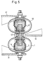
- FIG. 5 An extended embodiment is shown in FIG. 5, in which a spring body 1 and 40 ⁇ are arranged above and below the motor support arm 32, which are supported against body support arms 31 and 41. Both spring bodies 1 and 40 ⁇ with their bellows 2 and 42 are constructed identically, but arranged in mirror image to one another. Such an arrangement and configuration result in a pump effect in both directions of operation, which in particular prevents cavitation.
Landscapes
- Engineering & Computer Science (AREA)
- General Engineering & Computer Science (AREA)
- Mechanical Engineering (AREA)
- Health & Medical Sciences (AREA)
- Child & Adolescent Psychology (AREA)
- Combined Devices Of Dampers And Springs (AREA)
- Support Of The Bearing (AREA)
- Arrangement Or Mounting Of Propulsion Units For Vehicles (AREA)
Applications Claiming Priority (2)
| Application Number | Priority Date | Filing Date | Title |
|---|---|---|---|
| DE4106838A DE4106838A1 (de) | 1991-03-04 | 1991-03-04 | Daempfendes aggregatlager |
| DE4106838 | 1991-03-04 |
Publications (2)
| Publication Number | Publication Date |
|---|---|
| EP0502458A2 true EP0502458A2 (fr) | 1992-09-09 |
| EP0502458A3 EP0502458A3 (en) | 1992-10-28 |
Family
ID=6426421
Family Applications (1)
| Application Number | Title | Priority Date | Filing Date |
|---|---|---|---|
| EP19920103557 Ceased EP0502458A3 (en) | 1991-03-04 | 1992-03-02 | Damping support |
Country Status (4)
| Country | Link |
|---|---|
| US (1) | US5193788A (fr) |
| EP (1) | EP0502458A3 (fr) |
| JP (1) | JPH0599265A (fr) |
| DE (1) | DE4106838A1 (fr) |
Cited By (1)
| Publication number | Priority date | Publication date | Assignee | Title |
|---|---|---|---|---|
| FR2980253A1 (fr) * | 2011-09-15 | 2013-03-22 | Techlam | Dispositif destine a assurer un mouvement rotatif angulaire et/ou de torsion entre deux structures. |
Families Citing this family (20)
| Publication number | Priority date | Publication date | Assignee | Title |
|---|---|---|---|---|
| CA2094208A1 (fr) * | 1992-04-28 | 1993-10-29 | Richard D. Hein | Supports elastomeres amortisseurs pre-emballes; procede de fabrication; methode d'installation |
| FR2695620B1 (fr) * | 1992-09-17 | 1994-11-10 | Aerospatiale Ste Nat Indle | Dispositif de suspension pour relier un équipement embarqué à la structure d'un véhicule. |
| US5771816A (en) * | 1994-10-26 | 1998-06-30 | Knight Industries, Inc. | Lift table |
| GB2316731B (en) * | 1996-07-29 | 2000-09-27 | Draftex Ind Ltd | Vibration damping assemblies |
| JPH11315883A (ja) | 1998-04-30 | 1999-11-16 | Canon Inc | 除振装置、露光装置およびデバイス製造方法 |
| GB2339259B (en) * | 1998-07-07 | 2002-09-04 | Draftex Ind Ltd | Anti-vibration apparatus |
| DE10000150A1 (de) * | 2000-01-06 | 2001-07-12 | Buehler Ag | Vorrichtung zur elastischen Lagerung von Maschinen |
| US6491289B1 (en) * | 2000-11-14 | 2002-12-10 | Elyakim Schaap | Oleo-pneumatic shock absorbing system |
| US6691989B1 (en) * | 2002-08-16 | 2004-02-17 | Bfs Diversified Products, Llc | Variable rate air spring assembly |
| DE102005059180A1 (de) * | 2005-12-12 | 2007-06-14 | Robert Bosch Gmbh | Handwerkzeugmaschine mit einem Antriebsstrang und einer Entkopplungseinheit |
| DE102006036343B4 (de) * | 2006-08-03 | 2012-06-06 | Trelleborg Automotive Germany Gmbh | Dämpfendes Aggregatlager |
| JP5248852B2 (ja) * | 2007-12-27 | 2013-07-31 | ヤマハ発動機株式会社 | 車体用振動減衰装置 |
| FR2949250B1 (fr) * | 2009-08-24 | 2012-01-06 | Aliaxis R & D Sas | Pont amortissant |
| JP5765065B2 (ja) * | 2011-06-06 | 2015-08-19 | いすゞ自動車株式会社 | アクティブマウント装置及びそれを搭載した車両 |
| KR101738018B1 (ko) * | 2011-08-19 | 2017-05-19 | 현대자동차주식회사 | 서브프레임용 롤로드의 구조 |
| CN103075461B (zh) * | 2011-10-25 | 2015-09-02 | 株洲时代新材料科技股份有限公司 | 减振支撑装置 |
| US20130154170A1 (en) * | 2011-12-20 | 2013-06-20 | Honeywell International Inc. | Passive isolation devices providing low frequency damping of low mass payloads and spacecraft isolation systems employing the same |
| DE102014102330A1 (de) * | 2014-02-24 | 2015-08-27 | ThyssenKrupp Federn und Stabilisatoren GmbH | Tragfedereinheit für ein Fahrzeugfahrwerk |
| CN112901698A (zh) * | 2021-03-10 | 2021-06-04 | 北京航空航天大学 | 一种等温空气弹簧 |
| US11831215B2 (en) * | 2021-05-06 | 2023-11-28 | Aac Microtech (Changzhou) Co., Ltd. | Linear vibration motor |
Family Cites Families (13)
| Publication number | Priority date | Publication date | Assignee | Title |
|---|---|---|---|---|
| US2032659A (en) * | 1933-11-27 | 1936-03-03 | United States Gypsum Co | Antivibration machine base |
| US2572919A (en) * | 1943-04-30 | 1951-10-30 | Barr & Stroud Ltd | Vibration damping mounting for optical observation instruments |
| DE1778134U (de) * | 1956-09-25 | 1958-11-20 | Maschf Augsburg Nuernberg Ag | Mit fahrzeugfedern parallel geschalteter hydraulischer stossdaempfer. |
| EP0015378B1 (fr) * | 1979-03-01 | 1984-04-25 | Messerschmitt-Bölkow-Blohm Gesellschaft mit beschränkter Haftung | Isolateur de vibrations |
| IT1165137B (it) * | 1979-06-29 | 1987-04-22 | Gomma Antivibranti Applic | Sopporto ammortizzante per la sospensione di un corpo oscillante ad una struttura di sopporto,particolarmente per la sospensione del motore al telaio di un autoveicolo |
| US4733854A (en) * | 1983-06-10 | 1988-03-29 | Honda Giken Kogyo Kabushiki Kaisha | Fluid sealed mounting |
| GB8517575D0 (en) * | 1985-07-11 | 1985-08-14 | Gkn Technology Ltd | Spring assemblies |
| JPS62261728A (ja) * | 1986-05-09 | 1987-11-13 | Kiyuubitsuku Eng:Kk | ベロ−ズ型振動吸収器 |
| US4974820A (en) * | 1986-05-09 | 1990-12-04 | Suzuki Sogyo Kabushiki Kaisha | Bellows type shock absorber |
| GB8730005D0 (en) * | 1987-12-23 | 1988-02-03 | Avon Ind Polymers | Hydraulically damped mounting device |
| DE3908474A1 (de) * | 1988-07-22 | 1990-01-25 | Metzeler Gmbh | Ringfoermiger federkoerper aus faserverbundwerkstoffen |
| DE3915311A1 (de) * | 1989-05-10 | 1990-11-22 | Metzeler Gmbh | Hydraulisch wirkendes daempfungselement |
| DE3938383C1 (fr) * | 1989-11-18 | 1990-11-22 | Metzeler Gmbh, 8000 Muenchen, De |
-
1991
- 1991-03-04 DE DE4106838A patent/DE4106838A1/de not_active Withdrawn
-
1992
- 1992-03-02 EP EP19920103557 patent/EP0502458A3/de not_active Ceased
- 1992-03-04 JP JP4083338A patent/JPH0599265A/ja active Pending
- 1992-03-04 US US07/845,728 patent/US5193788A/en not_active Expired - Fee Related
Non-Patent Citations (2)
| Title |
|---|
| HOFMANN M.: "Neue Konzepte für Motorlagerungen", FAHRWERKTECHNIK * |
| SPURK H. J., ANDRÄ R.: "Theorie des Hydrolagers", AUTOMOBIL-INDUSTRIE, no. 5, pages 553 - 560 * |
Cited By (1)
| Publication number | Priority date | Publication date | Assignee | Title |
|---|---|---|---|---|
| FR2980253A1 (fr) * | 2011-09-15 | 2013-03-22 | Techlam | Dispositif destine a assurer un mouvement rotatif angulaire et/ou de torsion entre deux structures. |
Also Published As
| Publication number | Publication date |
|---|---|
| JPH0599265A (ja) | 1993-04-20 |
| EP0502458A3 (en) | 1992-10-28 |
| DE4106838A1 (de) | 1992-09-10 |
| US5193788A (en) | 1993-03-16 |
Similar Documents
| Publication | Publication Date | Title |
|---|---|---|
| EP0502458A2 (fr) | Support amortissant | |
| DE4305173C2 (de) | Hydraulisch dämpfende Lagerbuchse | |
| DE3908474C2 (fr) | ||
| DE69618126T2 (de) | Elastisches Lager mit Befestigungssystem das als Haltemechanismus funktioniert und Methode zu dessen Fertigung | |
| EP1484526B1 (fr) | Amortisseur de chocs avec amortissement dépendant de l'amplitude | |
| DE3139915A1 (de) | Luftgedaempftes gummilager | |
| EP0042908B1 (fr) | Support de moteur pour camions, autobus ou véhicules utilitaires semblables | |
| DE102012107558A1 (de) | Struktur eines Aufhängungshalters für einen Hilfsrahmen | |
| EP1173691A1 (fr) | Palier hydraulique | |
| DE3903143C2 (de) | Vorderradaufhängung für Kraftfahrzeuge mit Frontmotor | |
| EP2047138B1 (fr) | Support amortisseur de groupe | |
| EP0775844A2 (fr) | Support | |
| DE3940004A1 (de) | Motorlager mit hydraulischer daempfung | |
| DE3840156C2 (fr) | ||
| DE10035024A1 (de) | Hydraulisch dämpfendes Elastomerlager | |
| EP0543082B1 (fr) | Manchon hydraulique à plusieurs compartiments | |
| WO2018171963A1 (fr) | Coussinet | |
| DE10142822A1 (de) | Innentilger | |
| DE3036418A1 (de) | Schwingungsdaempfer | |
| EP1672242A1 (fr) | Support de moteur | |
| DE19537462C2 (de) | Aggregatelager | |
| DE102015224937A1 (de) | Hydrolager sowie Kraftfahrzeug mit einem derartigen Hydrolager | |
| EP2820322B1 (fr) | Palier hydraulique | |
| DE2933726A1 (de) | Schwingungsdaempfer | |
| DE69001875T2 (de) | Elastisches Lager, insbesondere für einen Fahrzeugmotor. |
Legal Events
| Date | Code | Title | Description |
|---|---|---|---|
| PUAI | Public reference made under article 153(3) epc to a published international application that has entered the european phase |
Free format text: ORIGINAL CODE: 0009012 |
|
| PUAL | Search report despatched |
Free format text: ORIGINAL CODE: 0009013 |
|
| AK | Designated contracting states |
Kind code of ref document: A2 Designated state(s): DE ES FR GB IT SE |
|
| AK | Designated contracting states |
Kind code of ref document: A3 Designated state(s): DE ES FR GB IT SE |
|
| 17P | Request for examination filed |
Effective date: 19921121 |
|
| 17Q | First examination report despatched |
Effective date: 19940208 |
|
| GRAG | Despatch of communication of intention to grant |
Free format text: ORIGINAL CODE: EPIDOS AGRA |
|
| STAA | Information on the status of an ep patent application or granted ep patent |
Free format text: STATUS: THE APPLICATION HAS BEEN REFUSED |
|
| 18R | Application refused |
Effective date: 19980802 |