EP0502344B1 - Vorrichtung zur Herstellung von bandförmigen Metallfolien - Google Patents
Vorrichtung zur Herstellung von bandförmigen Metallfolien Download PDFInfo
- Publication number
- EP0502344B1 EP0502344B1 EP92102406A EP92102406A EP0502344B1 EP 0502344 B1 EP0502344 B1 EP 0502344B1 EP 92102406 A EP92102406 A EP 92102406A EP 92102406 A EP92102406 A EP 92102406A EP 0502344 B1 EP0502344 B1 EP 0502344B1
- Authority
- EP
- European Patent Office
- Prior art keywords
- nozzle
- substrate
- space
- chamber
- pressure
- Prior art date
- Legal status (The legal status is an assumption and is not a legal conclusion. Google has not performed a legal analysis and makes no representation as to the accuracy of the status listed.)
- Expired - Lifetime
Links
- 239000011888 foil Substances 0.000 title claims abstract description 48
- 239000002184 metal Substances 0.000 title claims abstract description 38
- 239000000758 substrate Substances 0.000 claims abstract description 46
- 239000012768 molten material Substances 0.000 claims abstract description 18
- 239000007858 starting material Substances 0.000 claims abstract description 12
- 238000001816 cooling Methods 0.000 claims abstract description 11
- 230000015572 biosynthetic process Effects 0.000 claims abstract description 4
- 238000007599 discharging Methods 0.000 claims abstract 2
- 238000004519 manufacturing process Methods 0.000 claims description 4
- 238000010438 heat treatment Methods 0.000 claims description 2
- 238000002844 melting Methods 0.000 claims description 2
- 230000008018 melting Effects 0.000 claims description 2
- 239000000155 melt Substances 0.000 description 17
- 238000004891 communication Methods 0.000 description 4
- 230000001965 increasing effect Effects 0.000 description 3
- 238000003723 Smelting Methods 0.000 description 2
- 230000003750 conditioning effect Effects 0.000 description 2
- 238000006073 displacement reaction Methods 0.000 description 2
- 230000005484 gravity Effects 0.000 description 2
- 238000000034 method Methods 0.000 description 2
- 230000004048 modification Effects 0.000 description 2
- 238000012986 modification Methods 0.000 description 2
- 238000005266 casting Methods 0.000 description 1
- 230000007547 defect Effects 0.000 description 1
- 230000001419 dependent effect Effects 0.000 description 1
- 230000006866 deterioration Effects 0.000 description 1
- 230000001627 detrimental effect Effects 0.000 description 1
- 230000003467 diminishing effect Effects 0.000 description 1
- 230000002708 enhancing effect Effects 0.000 description 1
- 239000012535 impurity Substances 0.000 description 1
- 229910000953 kanthal Inorganic materials 0.000 description 1
- 239000000463 material Substances 0.000 description 1
- 239000007769 metal material Substances 0.000 description 1
- 239000002245 particle Substances 0.000 description 1
- 230000001105 regulatory effect Effects 0.000 description 1
- XLYOFNOQVPJJNP-UHFFFAOYSA-N water Substances O XLYOFNOQVPJJNP-UHFFFAOYSA-N 0.000 description 1
Images

Classifications
-
- B—PERFORMING OPERATIONS; TRANSPORTING
- B22—CASTING; POWDER METALLURGY
- B22D—CASTING OF METALS; CASTING OF OTHER SUBSTANCES BY THE SAME PROCESSES OR DEVICES
- B22D11/00—Continuous casting of metals, i.e. casting in indefinite lengths
- B22D11/06—Continuous casting of metals, i.e. casting in indefinite lengths into moulds with travelling walls, e.g. with rolls, plates, belts, caterpillars
- B22D11/0637—Accessories therefor
- B22D11/0697—Accessories therefor for casting in a protected atmosphere
Definitions
- the present invention relates to an apparatus for producing metal foils from molten starting material according to the preamble of claim 1.
- US-A-4,142,571 a further prior art apparatus has a nozzle directed towards the circumferential surface of a rotary roller or drum, the opening of the nozzle located a short distance from the circumferential surface being connected to a reservoir for heated molten metal material disposed above the nozzle through a slot-shaped nozzle channel connecting the nozzle opening and the reservoir.
- the reservoir is connected to a pressure source by means of which molten material may be urged from the reservoir through the nozzle channel and the nozzle opening out onto the circumferential surface for cooling, for the formation of a metal foil.
- the air interface In order to avoid or minimize the risk of quality deterioration caused by such air pockets, the air interface must, therefore, be displaced, which, in the prior art apparatus, is achieved partly by the proximity of the nozzle opening to the substrate and partly by the pressure of the melt forced through the nozzle opening against the substrate. Since the melt pressure against the substrate displacing the interface layer of air in a given nozzle design (the slot width of the nozzle channel and nozzle opening) is, in all essentials, dependant upon the pressure applied to the molten material in the reservoir, the applied pressure must, hence, be kept above a certain minimum pressure level in order to achieve the desired air displacement. Since the applied pressure, in a given nozzle design, also influences the quantity of positively discharged melt and ultimately the thickness of the finished foil, the pressure should, moreover, be kept as constant as possible in order to ensure a uniform foil thickness.
- DE-C-2 950 406 describes an apparatus for producing metal foils where the area above the substrate in front of the nozzle is covered by a chamber which implies pressure by a partial vacuum and heat to the surface of the substrate in order to ameliorate the quality of the foil and to vary the length of the metal foil which is in contact with the substrate.
- EP-A-0 208 890 describes a similar apparatus where the chamber is located around the nozzle in order to vary the distance between the nozzle and the substrate to be able to produce foils with different thicknesses.
- the chamber acts like an air or gas cushion on which the nozzle is situated, also to ameliorate the quality of the foil.
- US-A-4 649 984 comprises an apparatus with a conditioning chamber as a shield around the nozzle for minimizing an intrusion of ambient atmosphere into the chamber.
- Gas control provides a selected, low density atmosphere, such as a partial vacuum, within the conditioning chamber. This improves the surface finish of the cast strip and minimizes air pocket type defects.
- the thickness of the metal foil in a given nozzle design is, in all essentials, dependant upon the pressure which is applied to the molten material in the reservoir and which in turn determines the quantity of extruded melt.
- the foil thickness increases, while consequentially diminishing at the same rate as the quantity of discharged melt is reduced.
- Such a pressure reduction entails, at the same time, that the melt pressure against the substrate which displaces the interface air layer is reduced, with resultant increased risk of air pockets between the melt and the substrate, which disrupt the cooling process and thereby impair the quality of the finished foil.
- a modification of nozzle design i.e. nozzle channel and nozzle opening with smaller slot width
- a nozzle design with reduced slot width of nozzle channel and nozzle opening is highly sensitive to and places great demands on the purity of the molten starting material which should, therefore, be pure and wholly free of large-sized impurities in order to be able to pass through the nozzle channel and nozzle opening without becoming stuck and clogging the passage. Consequently, using the prior art apparatus, it is not possible to produce a metal foil of a thickness of less than 50 ⁇ m, for example 10-20 ⁇ m, without employing an extremely pure - and thereby expensive - starting material, which is a contributory factor in drastically raising the price of the finally produced metal foil.
- One object of the present invention is, therefore, to propose an apparatus of the type described by way of introduction which permits production of a metal foil of desired large (eg. 50 ⁇ m) or lesser (eg. 10-20 ⁇ m) thickness and with uniform foil qualities without suffering from the consequential drawbacks of the type inherent in the prior art apparatus.
- Another object of the present invention is to devize an apparatus of the described type which makes possible the production of an extremely thin (10-20 um) metal foil using the cheapest concievable starting material (metal scrap), without the risk of clogging of the channel and/or the opening in the nozzle employed.
- the pressure difference created by the vacuum chamber or the pressure chamber, respectively, in the space between the substrate and the nozzle it is thus possible to maintain a sufficiently high, constant melt pressure against the substrate, i.e. a melt pressure which is wholly independent of both the quantity of the melt supplied through the nozzle opening and any possible pressure variations occurring in the inflowing melt.
- the constant melt pressure realized by the pressure difference creates extraordinarily good pre-conditions for producing a metal foil of uniform superior surface qualities, at the same time as naturally also contributing to enhancing the efficiency of contact between the melt and the substrate, and thereby the cooling cycle of the melt.
- melt pressure against the substrate may be kept constant irrespective of the quantity of melt which is supplied, which implies that metal foils of different, both large and small thicknesses, may be produced without the need for modifying the design of the nozzle (the slot width of the nozzle channel and the nozzle opening).
- metal foils of very large thicknesses eg. above 50 ⁇ m, as well as metal foils of very slight thicknesses, eg. 10-20 ⁇ m, may be produced employing one and the same nozzle design.
- this entails that the slot width of the nozzle channel and nozzle opening may be very large, of the order of 2-3 mm, for which reason the nozzle will be less sensitive, or completely insensitive, to the purity of the starting material employed, even if metal foils of very slight thicknesses (10-20 ⁇ m) are to be produced.
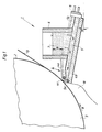
- the apparatus 1 which is schematically illustrated in partial section in Fig. 1 has been given the generic reference numeral 1.
- the apparatus 1 includes a movable, cooling substrate which, in the illustrated embodiment, consists of the circumferential or casing surface 2 of a roller or drum 3 rotary about a horizontal axis in the direction of the arrow A.
- the nozzle channel 5 is in communication with a reservoir 6 for molten starting material 7, eg. metal scrap, and is provided with a rear portion 5b extending beyond the reservoir 6 and being closed by means of an openable hatch or door 8.
- the nozzle 4 is arranged so that the nozzle channel 5 inclines somewhat upwardly towards the roller 3 in relation to the horizontal plane, as is intimated by the angle of inclination ⁇ marked at the rear region of the nozzle.
- the nozzle 4 is further arranged so that the nozzle opening 4c discharges a very short distance (approx. 0.3 mm at the lower nozzle lip 4b and the upper nozzle lip 4a) from the circumferential surface 2 in a region and on a level below the horizontal axis of rotation (not shown) of the roller 3, i.e. in a region located within the fourth quadrant of a coordinate system with zero point in the axis of rotation of the roller.
- Fig. 2 which schematically illustrates the region of the nozzle opening 4c on a larger scale
- a space 9 which is in communication with or communicable with a vacuum chamber 10.
- the space 9 is of elongate, slot-shaped design with a substantially constant slot width (approx. 0.3 mm) throughout its entire axial extent.
- a slot-shaped elongate space 11 of the same slot width (i.e. approx. 0.3 mm) as the space 9.
- heating devices 12 for instance glowing kanthal tubes, are provided in both the upper and lower nozzle lips 4a, 4b, respectively, by means of which tubes the molten material is prevented from cooling before exiting from the nozzle 4.
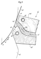
- Fig. 3 shows the discharge portion of a nozzle according to another embodiment of the present invention and, for purposes of clarity, the same reference numerals as in Fig. 2 have been employed for corresponding parts, with the addition of a primo symbol.
- the nozzle 4' in Fig. 3 thus includes an upper and a lower nozzle 4a' and 4b', respectively, which therebetween define a nozzle channel 5'.
- a similarly elongate space 9' which is in communication with or communicable with a vacuum chamber 10'.
- the space 9' differs from the space 9 of Fig.
- the space 11' between the upper nozzle lip 4a' and the surface 2' is, on the other hand, substantially of constant slot width throughout its entire axial extent.
- the apparatus 1 in Figs. 1 and 2 produces a web-shaped metal foil 13 in the following manner.
- the space 9 is placed in communication with the vacuum chamber 10 and molten material 7 runs by force of gravity from the reservoir 6 through the nozzle channel 5 out through the nozzle opening 4c for forming a so-called melt puddle 7' in the region of the nozzle opening.
- the pressure eg. 70-90 cm water column
- the rear portion of the melt puddle will be sucked into the space 9 and thereby against the circumferential surface 2 at constant, sufficiently high pressure to displace the interface layer of air which accompanies the circumferential surface moving in the direction of the arrow A (eg. at 30 m/s).
- the melt puddle On contact with the cooling (approx. 170 o C) substrate, the melt puddle is cooled from beneath for the formation of a metal foil 13 accompanying the circumferential surface 2, the metal foil being, after passage through the space 11, unwound from the circumferential surface and wound up into a roll of foil.
- metal foils may be produced in this manner with varying, but in every individual case uniform thicknesses and of uniform superior surface qualities. If, for example, a metal foil of a given thickness (50 ⁇ m) is desired, the quantity of supplied melt is correspondingly regulated, while, if a metal foil of a lesser thickness (10-20 ⁇ m) is to be produced, a correspondingly reduced quantity of melt is supplied.
- the quantity of melt which is supplied in each individual case is, to all essentials, determined by the level difference (h) between the surface of the melt in the reservoir 6 and the nozzle opening 4c, which is easy to regulate by the controlled supply of new melt from the smelting furnace (not shown).
- a metal foil 13' is produced using the nozzle 4' illustrated in Fig. 3.
- the advantage inherent in this nozzle is that the vacuum in the space 9' need not be of such magnitude as the corresponding vacuum in the space 9 to achieve the contemplated sufficiently high melt pressure against the circumferential surface 2', since the tapering cross section of the space gives rise to a pressure réelle directed towards the circumferential surface and increasing in a direction rearwardly from the nozzle opening 4c'.
- the nozzle 4' can be instrumental in producing metal foils of varying, but in each individual case uniform thicknesses and of uniform superior surface qualities.
- a metal foil may be produced of a thickness of approx.
- the apparatus according to the present invention may, instead of the vacuum chamber described in the foregoing and specifically shown on the Drawings, be provided with a pressure chamber between the nozzle and the substrate, in order to press the melt at constant pressure against the substrate.
- the pressure chamber should ideally be disposed ahead of the melt supplied through the nozzle (seen in the direction of movement of the substrate).
- the constant high melt pressure against the substrate is catered for by the pressure difference which the apparatus creates between the nozzle and the substrate and which is either achieved by means of the space communicable with the vacuum chamber or the space communicable with the pressure chamber, as described above.
Landscapes
- Engineering & Computer Science (AREA)
- Mechanical Engineering (AREA)
- Continuous Casting (AREA)
- Laminated Bodies (AREA)
Claims (13)
- Vorrichtung zur Herstellung bandförmiger Metallfolien (13; 13') aus einem geschmolzenen Ausgangsmaterial (7), wobei die Vorrichtung folgendes umfaßt:ein bewegliches Kühlsubstrat (2; 2'), das aus der Umfangsfläche einer Drehwalze oder einer Trommel (3) besteht, sowie eine Düse (4; 4'), die geschmolzenes Material abgibt, das zum Aufbringen auf das Substrat vorgesehen ist, um die Metallfolie zu bilden, wobei ein Raum (9; 9') zwischen der Düse (4; 4') und dem Substrat (2; 2') vorgesehen ist, der mit einer Kammer (10; 10') in Verbindung gebracht werden kann, wobei in dem Raum (9; 9') eine Druckdifferenz bezüglich der Umgebungsatmosphäre hergestellt werden kann,
dadurch gekennzeichnet, daßdie Kammer (10; 10') eine Vakuumkammer oder eine Druckkammer ist, daßdie Druckdifferenz einen konstanten Schmelzendruck des geschmolzenen Materials gegen das Substrat (2; 2') aufrechterhält, und daß die Düse (4; 4') auf einem Niveau unter der horizontalen Drehachse der Walze (3) angeordnet ist. - Vorrichtung nach Anspruch 1,
dadurch gekennzeichnet, daßdie Düse (4; 4') derart angeordnet ist, daß der Düsenkanal (5) bezüglich der horizontalen Ebene nach oben zu der Walze (3) geneigt ist. - Vorrichtung nach Anspruch 1 oder 2,
dadurch gekennzeichnet, daßdie Düse (4; 4') in einem Bereich innerhalb des vierten Quadranten eines Koordinatensystems mit dem Nullpunkt in der Drehachse der Walze (3) liegt, die sich gegen den Uhrzeigersinn dreht. - Vorrichtung nach einem der vorhergehenden Ansprüche,
dadurch gekennzeichnet, daßdie Düse (4; 4') auf einem Niveau unter der Drehachse der Walze angeordnet ist. - Vorrichtung nach einem der vorhergehenden Ansprüche,
dadurch gekennzeichnet, daßdie Druckdifferenz das geschmolzene Material in Kontakt mit dem Substrat (2; 2') saugt oder preßt. - Vorrichtung nach einem der vorhergehenden Ansprüche,
dadurch gekennzeichnet, daßdie Dicke der Metallfolie zwischen 10 und 20 µm oder darüber liegt. - Vorrichtung nach einem der vorhergehenden Ansprüche,
dadurch gekennzeichnet, daßder Raum (9; 9') länglich ist, wobei die Längsachse des Raums im wesentlichen parallel zu dem Substrat liegt. - Vorrichtung nach einem der vorhergehenden Ansprüche,
dadurch gekennzeichnet, daßder Raum (9; 9') in Richtung von der Öffnung (4c') der Düse weg verjüngt ist. - Vorrichtung nach einem der vorhergehenden Ansprüche,
dadurch gekennzeichnet, daßdie Düse (4; 4') eine obere (4a; 4a') und eine untere Lippe (4b; 4b') umfaßt, die zusammen eine Düsenöffnung (4c; 4c') bilden, die zu dem Substrat (2; 2') gerichtet ist, wobei der mit der Kammer (10; 10') in Verbindung zu bringende Raum (9; 9') zwischen dem Substrat und der unteren Lippe angeordnet ist. - Vorrichtung nach einem der vorhergehenden Ansprüche,
dadurch gekennzeichnet, daßder Abstand zwischen dem Substrat (2; 2') und der unteren Lippe (4b; 4b') kleiner als der Abstand zwischen dem Substrat und der oberen Lippe (4a; 4a') ist. - Vorrichtung nach einem der vorhergehenden Ansprüche,
dadurch gekennzeichnet, daßder Abstand zwischen der unteren Lippe (4b; 4b') und dem Substrat (2; 2') von der Düsenöffnung (4c; 4c') bezüglich der Bewegung des Substrats (2; 2') in Richtung nach hinten abnimmt. - Vorrichtung nach einem der vorhergehenden Ansprüche,
dadurch gekennzeichnet, daßdie obere und die untere Düsenlippe Heizeinrichtungen (12; 12') umfassen, um die Düse (4; 4') auf einer Temperatur über der Schmelztemperatur des Ausgangsmaterials zu halten. - Vorrichtung nach einem der vorhergehenden Ansprüche,
dadurch gekennzeichnet, daßder zu dem Behälter (6) hin angeordnete Teil des Kanals einen hinteren Abschnitt aufweist, der sich über den Behälter hinauserstreckt und mittels einer zu öffnenden Luke oder Tür (8) verschlossen ist.
Applications Claiming Priority (2)
| Application Number | Priority Date | Filing Date | Title |
|---|---|---|---|
| SE9100662 | 1991-03-06 | ||
| SE9100662A SE507606C2 (sv) | 1991-03-06 | 1991-03-06 | Anordning för framställning av banformig metallfolie |
Publications (2)
| Publication Number | Publication Date |
|---|---|
| EP0502344A1 EP0502344A1 (de) | 1992-09-09 |
| EP0502344B1 true EP0502344B1 (de) | 1997-12-03 |
Family
ID=20382075
Family Applications (1)
| Application Number | Title | Priority Date | Filing Date |
|---|---|---|---|
| EP92102406A Expired - Lifetime EP0502344B1 (de) | 1991-03-06 | 1992-02-13 | Vorrichtung zur Herstellung von bandförmigen Metallfolien |
Country Status (6)
| Country | Link |
|---|---|
| EP (1) | EP0502344B1 (de) |
| JP (1) | JP2966995B2 (de) |
| AT (1) | ATE160714T1 (de) |
| DE (1) | DE69223336T2 (de) |
| ES (1) | ES2110450T3 (de) |
| SE (1) | SE507606C2 (de) |
Families Citing this family (1)
| Publication number | Priority date | Publication date | Assignee | Title |
|---|---|---|---|---|
| IT1290932B1 (it) | 1997-02-14 | 1998-12-14 | Voest Alpine Ind Anlagen | Procedimento e dispositivo per impedire il contatto di ossigeno con una massa metallica fusa. |
Family Cites Families (4)
| Publication number | Priority date | Publication date | Assignee | Title |
|---|---|---|---|---|
| DE2825360C2 (de) * | 1978-06-09 | 1983-10-27 | Fried. Krupp Gmbh, 4300 Essen | Induktiv beheizte Rinne zum Zuführen von Metall in eine Stranggießkokille |
| DE2950406C2 (de) * | 1979-12-14 | 1986-12-04 | Hitachi Metals, Ltd., Tokyo | Vorrichtung zum Stranggießen eines Metallbandes |
| US4649984A (en) * | 1984-07-23 | 1987-03-17 | Allied Corporation | Method of and apparatus for casting metal strip employing a localized conditioning shoe |
| DE3683096D1 (de) * | 1985-06-19 | 1992-02-06 | Sundwiger Eisen Maschinen | Verfahren zum herstellen eines metallstranges, insbesondere in form eines bandes oder profils durch giessen und vorrichtung zur durchfuehrung dieses verfahrens. |
-
1991
- 1991-03-06 SE SE9100662A patent/SE507606C2/sv not_active IP Right Cessation
-
1992
- 1992-02-13 DE DE69223336T patent/DE69223336T2/de not_active Expired - Fee Related
- 1992-02-13 EP EP92102406A patent/EP0502344B1/de not_active Expired - Lifetime
- 1992-02-13 ES ES92102406T patent/ES2110450T3/es not_active Expired - Lifetime
- 1992-02-13 AT AT92102406T patent/ATE160714T1/de not_active IP Right Cessation
- 1992-03-05 JP JP4048493A patent/JP2966995B2/ja not_active Expired - Fee Related
Non-Patent Citations (2)
| Title |
|---|
| PATENT ABSTRACT OF JAPAN, Vol. 10, No. 47, (M-456), 9 October 1985; & JP-A-60-199552 (CHIN NIPPON SEITETSU K.K.) * |
| PATENT ABSTRACT OF JAPAN, Vol. 5, No. 53 (M-63), 29 January 1981; & JP-A-56-9046, (HITACHI SEISAKUSHO K.K.) * |
Also Published As
| Publication number | Publication date |
|---|---|
| JP2966995B2 (ja) | 1999-10-25 |
| JPH04319048A (ja) | 1992-11-10 |
| ES2110450T3 (es) | 1998-02-16 |
| DE69223336D1 (de) | 1998-01-15 |
| SE9100662D0 (sv) | 1991-03-06 |
| SE9100662L (sv) | 1992-09-07 |
| SE507606C2 (sv) | 1998-06-29 |
| ATE160714T1 (de) | 1997-12-15 |
| DE69223336T2 (de) | 1998-03-26 |
| EP0502344A1 (de) | 1992-09-09 |
Similar Documents
| Publication | Publication Date | Title |
|---|---|---|
| US5993939A (en) | Method for preparing permanent magnet material, chill roll, permanent magnet material, and permanent magnet material powder | |
| US5209789A (en) | Permanent magnet material and method for making | |
| US5624715A (en) | Method and apparatus for curtain coating a moving support | |
| GB2183185A (en) | A metal ribbon having a unidirectional crystalline structure is produced by continuous casting | |
| US4721152A (en) | Apparatus for continuous casting | |
| EP0502344A1 (de) | Vorrichtung zur Herstellung von bandförmigen Metallfolien | |
| US5040773A (en) | Method and apparatus for temperature-controlled skull melting | |
| EP0859675B1 (de) | Verfahren und vorrichtung zum giessen eines metallbandes | |
| JPH10511313A (ja) | 帯状金属板の連続的製造方法及び装置 | |
| AU2967592A (en) | Meniscus coating steel strip | |
| EP0463226B1 (de) | Verfahren und Einrichtung zum Bandstranggiessen | |
| US5728429A (en) | Method and a device for producing thin layers from liquids to form coating or foils | |
| FI78250C (fi) | Foerfarande och anordning foer direktgjutning av smaelt metall. | |
| EP0510419B1 (de) | Verfahren und Vorrichtung zum Aufbringen von schmelzflüssigen Metallüberzügen | |
| US4719963A (en) | Process for the production of a metal strand, more particularly in the form of a strip or section, by casting and apparatus for the performance of the process | |
| CA1233618A (en) | Method and apparatus for direct casting of crystalline strip in non-oxidizing atmosphere | |
| US4617981A (en) | Method and apparatus for strip casting | |
| NO165747B (no) | Fremgangsmaate og anordning ved stoeping av metall. | |
| US4375234A (en) | Electromagnetic thin strip casting process | |
| JPS642467B2 (de) | ||
| JPH07286266A (ja) | 蒸着装置および蒸着方法 | |
| EP1594640B1 (de) | Stahlbandgiessen | |
| KR100447279B1 (ko) | 금속박대의 제조장치 및 제조방법 | |
| EP0022566B1 (de) | Verfahren und Vorrichtung zum elektromagnetischen Formen geschmolzener Metalle oder Legierungen, Kühlmittelverteiler für das elektromagnetische Giessen | |
| EP1506825B1 (de) | Vorrichtung sowie Verfahren zur Erzeugung von dünnem Bimetallband mit einer 2-Rollen-Giessvorrichtung |
Legal Events
| Date | Code | Title | Description |
|---|---|---|---|
| PUAI | Public reference made under article 153(3) epc to a published international application that has entered the european phase |
Free format text: ORIGINAL CODE: 0009012 |
|
| AK | Designated contracting states |
Kind code of ref document: A1 Designated state(s): AT BE CH DE DK ES FR GB GR IT LI LU NL PT SE |
|
| 17P | Request for examination filed |
Effective date: 19921215 |
|
| RAP1 | Party data changed (applicant data changed or rights of an application transferred) |
Owner name: TETRA LAVAL HOLDINGS & FINANCE S.A. |
|
| 17Q | First examination report despatched |
Effective date: 19950824 |
|
| GRAG | Despatch of communication of intention to grant |
Free format text: ORIGINAL CODE: EPIDOS AGRA |
|
| GRAH | Despatch of communication of intention to grant a patent |
Free format text: ORIGINAL CODE: EPIDOS IGRA |
|
| GRAH | Despatch of communication of intention to grant a patent |
Free format text: ORIGINAL CODE: EPIDOS IGRA |
|
| GRAA | (expected) grant |
Free format text: ORIGINAL CODE: 0009210 |
|
| AK | Designated contracting states |
Kind code of ref document: B1 Designated state(s): AT BE CH DE DK ES FR GB GR IT LI LU NL PT SE |
|
| PG25 | Lapsed in a contracting state [announced via postgrant information from national office to epo] |
Ref country code: IT Free format text: LAPSE BECAUSE OF FAILURE TO SUBMIT A TRANSLATION OF THE DESCRIPTION OR TO PAY THE FEE WITHIN THE PRE;WARNING: LAPSES OF ITALIAN PATENTS WITH EFFECTIVE DATE BEFORE 2007 MAY HAVE OCCURRED AT ANY TIME BEFORE 2007. THE CORRECT EFFECTIVE DATE MAY BE DIFFERENT FROM THE ONE RECORDED.SCRIBED TIME-LIMIT Effective date: 19971203 Ref country code: GR Free format text: LAPSE BECAUSE OF FAILURE TO SUBMIT A TRANSLATION OF THE DESCRIPTION OR TO PAY THE FEE WITHIN THE PRESCRIBED TIME-LIMIT Effective date: 19971203 Ref country code: BE Free format text: LAPSE BECAUSE OF FAILURE TO SUBMIT A TRANSLATION OF THE DESCRIPTION OR TO PAY THE FEE WITHIN THE PRESCRIBED TIME-LIMIT Effective date: 19971203 Ref country code: DK Free format text: LAPSE BECAUSE OF NON-PAYMENT OF DUE FEES Effective date: 19971203 Ref country code: CH Free format text: LAPSE BECAUSE OF FAILURE TO SUBMIT A TRANSLATION OF THE DESCRIPTION OR TO PAY THE FEE WITHIN THE PRESCRIBED TIME-LIMIT Effective date: 19971203 Ref country code: AT Free format text: LAPSE BECAUSE OF FAILURE TO SUBMIT A TRANSLATION OF THE DESCRIPTION OR TO PAY THE FEE WITHIN THE PRESCRIBED TIME-LIMIT Effective date: 19971203 Ref country code: NL Free format text: LAPSE BECAUSE OF FAILURE TO SUBMIT A TRANSLATION OF THE DESCRIPTION OR TO PAY THE FEE WITHIN THE PRESCRIBED TIME-LIMIT Effective date: 19971203 Ref country code: LI Free format text: LAPSE BECAUSE OF FAILURE TO SUBMIT A TRANSLATION OF THE DESCRIPTION OR TO PAY THE FEE WITHIN THE PRESCRIBED TIME-LIMIT Effective date: 19971203 |
|
| REF | Corresponds to: |
Ref document number: 160714 Country of ref document: AT Date of ref document: 19971215 Kind code of ref document: T |
|
| REG | Reference to a national code |
Ref country code: CH Ref legal event code: EP |
|
| ET | Fr: translation filed | ||
| REF | Corresponds to: |
Ref document number: 69223336 Country of ref document: DE Date of ref document: 19980115 |
|
| PG25 | Lapsed in a contracting state [announced via postgrant information from national office to epo] |
Ref country code: LU Free format text: LAPSE BECAUSE OF NON-PAYMENT OF DUE FEES Effective date: 19980213 |
|
| REG | Reference to a national code |
Ref country code: ES Ref legal event code: FG2A Ref document number: 2110450 Country of ref document: ES Kind code of ref document: T3 |
|
| PG25 | Lapsed in a contracting state [announced via postgrant information from national office to epo] |
Ref country code: PT Free format text: LAPSE BECAUSE OF FAILURE TO SUBMIT A TRANSLATION OF THE DESCRIPTION OR TO PAY THE FEE WITHIN THE PRESCRIBED TIME-LIMIT Effective date: 19980303 Ref country code: SE Free format text: LAPSE BECAUSE OF FAILURE TO SUBMIT A TRANSLATION OF THE DESCRIPTION OR TO PAY THE FEE WITHIN THE PRESCRIBED TIME-LIMIT Effective date: 19980303 |
|
| NLV1 | Nl: lapsed or annulled due to failure to fulfill the requirements of art. 29p and 29m of the patents act | ||
| REG | Reference to a national code |
Ref country code: CH Ref legal event code: PL |
|
| PLBE | No opposition filed within time limit |
Free format text: ORIGINAL CODE: 0009261 |
|
| STAA | Information on the status of an ep patent application or granted ep patent |
Free format text: STATUS: NO OPPOSITION FILED WITHIN TIME LIMIT |
|
| 26N | No opposition filed | ||
| REG | Reference to a national code |
Ref country code: GB Ref legal event code: IF02 |
|
| PGFP | Annual fee paid to national office [announced via postgrant information from national office to epo] |
Ref country code: GB Payment date: 20070223 Year of fee payment: 16 |
|
| PGFP | Annual fee paid to national office [announced via postgrant information from national office to epo] |
Ref country code: ES Payment date: 20070226 Year of fee payment: 16 |
|
| PGFP | Annual fee paid to national office [announced via postgrant information from national office to epo] |
Ref country code: DE Payment date: 20070330 Year of fee payment: 16 |
|
| PGFP | Annual fee paid to national office [announced via postgrant information from national office to epo] |
Ref country code: FR Payment date: 20070221 Year of fee payment: 16 |
|
| GBPC | Gb: european patent ceased through non-payment of renewal fee |
Effective date: 20080213 |
|
| REG | Reference to a national code |
Ref country code: FR Ref legal event code: ST Effective date: 20081031 |
|
| PG25 | Lapsed in a contracting state [announced via postgrant information from national office to epo] |
Ref country code: DE Free format text: LAPSE BECAUSE OF NON-PAYMENT OF DUE FEES Effective date: 20080902 |
|
| PG25 | Lapsed in a contracting state [announced via postgrant information from national office to epo] |
Ref country code: FR Free format text: LAPSE BECAUSE OF NON-PAYMENT OF DUE FEES Effective date: 20080229 |
|
| REG | Reference to a national code |
Ref country code: ES Ref legal event code: FD2A Effective date: 20080214 |
|
| PG25 | Lapsed in a contracting state [announced via postgrant information from national office to epo] |
Ref country code: GB Free format text: LAPSE BECAUSE OF NON-PAYMENT OF DUE FEES Effective date: 20080213 |
|
| PG25 | Lapsed in a contracting state [announced via postgrant information from national office to epo] |
Ref country code: ES Free format text: LAPSE BECAUSE OF NON-PAYMENT OF DUE FEES Effective date: 20080214 |