EP0501477B1 - Information processing apparatus - Google Patents
Information processing apparatus Download PDFInfo
- Publication number
- EP0501477B1 EP0501477B1 EP92103367A EP92103367A EP0501477B1 EP 0501477 B1 EP0501477 B1 EP 0501477B1 EP 92103367 A EP92103367 A EP 92103367A EP 92103367 A EP92103367 A EP 92103367A EP 0501477 B1 EP0501477 B1 EP 0501477B1
- Authority
- EP
- European Patent Office
- Prior art keywords
- floating
- magneto
- magnetic head
- optical disk
- recording medium
- Prior art date
- Legal status (The legal status is an assumption and is not a legal conclusion. Google has not performed a legal analysis and makes no representation as to the accuracy of the status listed.)
- Expired - Lifetime
Links
- 230000010365 information processing Effects 0.000 title claims description 22
- 239000000725 suspension Substances 0.000 claims description 73
- 238000000034 method Methods 0.000 claims description 29
- 230000008569 process Effects 0.000 claims description 15
- 238000013459 approach Methods 0.000 claims description 3
- 230000003287 optical effect Effects 0.000 description 33
- 238000002474 experimental method Methods 0.000 description 15
- 239000000758 substrate Substances 0.000 description 11
- 230000006870 function Effects 0.000 description 10
- 239000010408 film Substances 0.000 description 9
- 230000001965 increasing effect Effects 0.000 description 6
- 238000001514 detection method Methods 0.000 description 5
- 238000011068 loading method Methods 0.000 description 5
- 238000005259 measurement Methods 0.000 description 5
- 229910052751 metal Inorganic materials 0.000 description 5
- 239000002184 metal Substances 0.000 description 5
- 229920000515 polycarbonate Polymers 0.000 description 5
- 239000004417 polycarbonate Substances 0.000 description 5
- 230000012447 hatching Effects 0.000 description 4
- 239000011347 resin Substances 0.000 description 4
- 229920005989 resin Polymers 0.000 description 4
- 235000010724 Wisteria floribunda Nutrition 0.000 description 3
- 230000003247 decreasing effect Effects 0.000 description 3
- 239000011521 glass Substances 0.000 description 3
- 230000007257 malfunction Effects 0.000 description 3
- 230000001681 protective effect Effects 0.000 description 3
- 239000011241 protective layer Substances 0.000 description 3
- 230000008901 benefit Effects 0.000 description 2
- 238000012545 processing Methods 0.000 description 2
- 239000007787 solid Substances 0.000 description 2
- 229910045601 alloy Inorganic materials 0.000 description 1
- 239000000956 alloy Substances 0.000 description 1
- 239000011248 coating agent Substances 0.000 description 1
- 238000000576 coating method Methods 0.000 description 1
- 238000004891 communication Methods 0.000 description 1
- 238000005094 computer simulation Methods 0.000 description 1
- 230000008878 coupling Effects 0.000 description 1
- 238000010168 coupling process Methods 0.000 description 1
- 238000005859 coupling reaction Methods 0.000 description 1
- 238000013461 design Methods 0.000 description 1
- 230000002708 enhancing effect Effects 0.000 description 1
- 230000004907 flux Effects 0.000 description 1
- 238000003780 insertion Methods 0.000 description 1
- 230000037431 insertion Effects 0.000 description 1
- 239000000314 lubricant Substances 0.000 description 1
- 230000005415 magnetization Effects 0.000 description 1
- 239000000463 material Substances 0.000 description 1
- 230000007246 mechanism Effects 0.000 description 1
- 230000010287 polarization Effects 0.000 description 1
- 230000003252 repetitive effect Effects 0.000 description 1
- 230000035945 sensitivity Effects 0.000 description 1
- 125000006850 spacer group Chemical group 0.000 description 1
- 239000010935 stainless steel Substances 0.000 description 1
- 229910001220 stainless steel Inorganic materials 0.000 description 1
- 239000000126 substance Substances 0.000 description 1
- 239000010409 thin film Substances 0.000 description 1
- 238000012546 transfer Methods 0.000 description 1
- 229910052723 transition metal Inorganic materials 0.000 description 1
Images


Classifications
-
- G—PHYSICS
- G11—INFORMATION STORAGE
- G11B—INFORMATION STORAGE BASED ON RELATIVE MOVEMENT BETWEEN RECORD CARRIER AND TRANSDUCER
- G11B19/00—Driving, starting, stopping record carriers not specifically of filamentary or web form, or of supports therefor; Control thereof; Control of operating function ; Driving both disc and head
- G11B19/20—Driving; Starting; Stopping; Control thereof
-
- G—PHYSICS
- G11—INFORMATION STORAGE
- G11B—INFORMATION STORAGE BASED ON RELATIVE MOVEMENT BETWEEN RECORD CARRIER AND TRANSDUCER
- G11B11/00—Recording on or reproducing from the same record carrier wherein for these two operations the methods are covered by different main groups of groups G11B3/00 - G11B7/00 or by different subgroups of group G11B9/00; Record carriers therefor
- G11B11/12—Recording on or reproducing from the same record carrier wherein for these two operations the methods are covered by different main groups of groups G11B3/00 - G11B7/00 or by different subgroups of group G11B9/00; Record carriers therefor using recording by optical means
-
- G—PHYSICS
- G11—INFORMATION STORAGE
- G11B—INFORMATION STORAGE BASED ON RELATIVE MOVEMENT BETWEEN RECORD CARRIER AND TRANSDUCER
- G11B11/00—Recording on or reproducing from the same record carrier wherein for these two operations the methods are covered by different main groups of groups G11B3/00 - G11B7/00 or by different subgroups of group G11B9/00; Record carriers therefor
- G11B11/10—Recording on or reproducing from the same record carrier wherein for these two operations the methods are covered by different main groups of groups G11B3/00 - G11B7/00 or by different subgroups of group G11B9/00; Record carriers therefor using recording by magnetic means or other means for magnetisation or demagnetisation of a record carrier, e.g. light induced spin magnetisation; Demagnetisation by thermal or stress means in the presence or not of an orienting magnetic field
- G11B11/105—Recording on or reproducing from the same record carrier wherein for these two operations the methods are covered by different main groups of groups G11B3/00 - G11B7/00 or by different subgroups of group G11B9/00; Record carriers therefor using recording by magnetic means or other means for magnetisation or demagnetisation of a record carrier, e.g. light induced spin magnetisation; Demagnetisation by thermal or stress means in the presence or not of an orienting magnetic field using a beam of light or a magnetic field for recording by change of magnetisation and a beam of light for reproducing, i.e. magneto-optical, e.g. light-induced thermomagnetic recording, spin magnetisation recording, Kerr or Faraday effect reproducing
- G11B11/1055—Disposition or mounting of transducers relative to record carriers
- G11B11/10556—Disposition or mounting of transducers relative to record carriers with provision for moving or switching or masking the transducers in or out of their operative position
- G11B11/10558—Disposition or mounting of transducers relative to record carriers with provision for moving or switching or masking the transducers in or out of their operative position in view of the loading or unloading of the carrier
-
- G—PHYSICS
- G11—INFORMATION STORAGE
- G11B—INFORMATION STORAGE BASED ON RELATIVE MOVEMENT BETWEEN RECORD CARRIER AND TRANSDUCER
- G11B11/00—Recording on or reproducing from the same record carrier wherein for these two operations the methods are covered by different main groups of groups G11B3/00 - G11B7/00 or by different subgroups of group G11B9/00; Record carriers therefor
- G11B11/10—Recording on or reproducing from the same record carrier wherein for these two operations the methods are covered by different main groups of groups G11B3/00 - G11B7/00 or by different subgroups of group G11B9/00; Record carriers therefor using recording by magnetic means or other means for magnetisation or demagnetisation of a record carrier, e.g. light induced spin magnetisation; Demagnetisation by thermal or stress means in the presence or not of an orienting magnetic field
- G11B11/105—Recording on or reproducing from the same record carrier wherein for these two operations the methods are covered by different main groups of groups G11B3/00 - G11B7/00 or by different subgroups of group G11B9/00; Record carriers therefor using recording by magnetic means or other means for magnetisation or demagnetisation of a record carrier, e.g. light induced spin magnetisation; Demagnetisation by thermal or stress means in the presence or not of an orienting magnetic field using a beam of light or a magnetic field for recording by change of magnetisation and a beam of light for reproducing, i.e. magneto-optical, e.g. light-induced thermomagnetic recording, spin magnetisation recording, Kerr or Faraday effect reproducing
- G11B11/1055—Disposition or mounting of transducers relative to record carriers
- G11B11/10576—Disposition or mounting of transducers relative to record carriers with provision for moving the transducers for maintaining alignment or spacing relative to the carrier
-
- G—PHYSICS
- G11—INFORMATION STORAGE
- G11B—INFORMATION STORAGE BASED ON RELATIVE MOVEMENT BETWEEN RECORD CARRIER AND TRANSDUCER
- G11B11/00—Recording on or reproducing from the same record carrier wherein for these two operations the methods are covered by different main groups of groups G11B3/00 - G11B7/00 or by different subgroups of group G11B9/00; Record carriers therefor
- G11B11/10—Recording on or reproducing from the same record carrier wherein for these two operations the methods are covered by different main groups of groups G11B3/00 - G11B7/00 or by different subgroups of group G11B9/00; Record carriers therefor using recording by magnetic means or other means for magnetisation or demagnetisation of a record carrier, e.g. light induced spin magnetisation; Demagnetisation by thermal or stress means in the presence or not of an orienting magnetic field
- G11B11/105—Recording on or reproducing from the same record carrier wherein for these two operations the methods are covered by different main groups of groups G11B3/00 - G11B7/00 or by different subgroups of group G11B9/00; Record carriers therefor using recording by magnetic means or other means for magnetisation or demagnetisation of a record carrier, e.g. light induced spin magnetisation; Demagnetisation by thermal or stress means in the presence or not of an orienting magnetic field using a beam of light or a magnetic field for recording by change of magnetisation and a beam of light for reproducing, i.e. magneto-optical, e.g. light-induced thermomagnetic recording, spin magnetisation recording, Kerr or Faraday effect reproducing
- G11B11/1055—Disposition or mounting of transducers relative to record carriers
- G11B11/1058—Flying heads
-
- G—PHYSICS
- G11—INFORMATION STORAGE
- G11B—INFORMATION STORAGE BASED ON RELATIVE MOVEMENT BETWEEN RECORD CARRIER AND TRANSDUCER
- G11B11/00—Recording on or reproducing from the same record carrier wherein for these two operations the methods are covered by different main groups of groups G11B3/00 - G11B7/00 or by different subgroups of group G11B9/00; Record carriers therefor
- G11B11/10—Recording on or reproducing from the same record carrier wherein for these two operations the methods are covered by different main groups of groups G11B3/00 - G11B7/00 or by different subgroups of group G11B9/00; Record carriers therefor using recording by magnetic means or other means for magnetisation or demagnetisation of a record carrier, e.g. light induced spin magnetisation; Demagnetisation by thermal or stress means in the presence or not of an orienting magnetic field
- G11B11/105—Recording on or reproducing from the same record carrier wherein for these two operations the methods are covered by different main groups of groups G11B3/00 - G11B7/00 or by different subgroups of group G11B9/00; Record carriers therefor using recording by magnetic means or other means for magnetisation or demagnetisation of a record carrier, e.g. light induced spin magnetisation; Demagnetisation by thermal or stress means in the presence or not of an orienting magnetic field using a beam of light or a magnetic field for recording by change of magnetisation and a beam of light for reproducing, i.e. magneto-optical, e.g. light-induced thermomagnetic recording, spin magnetisation recording, Kerr or Faraday effect reproducing
- G11B11/10595—Control of operating function
-
- G—PHYSICS
- G11—INFORMATION STORAGE
- G11B—INFORMATION STORAGE BASED ON RELATIVE MOVEMENT BETWEEN RECORD CARRIER AND TRANSDUCER
- G11B17/00—Guiding record carriers not specifically of filamentary or web form, or of supports therefor
- G11B17/32—Maintaining desired spacing between record carrier and head, e.g. by fluid-dynamic spacing
-
- G—PHYSICS
- G11—INFORMATION STORAGE
- G11B—INFORMATION STORAGE BASED ON RELATIVE MOVEMENT BETWEEN RECORD CARRIER AND TRANSDUCER
- G11B21/00—Head arrangements not specific to the method of recording or reproducing
- G11B21/16—Supporting the heads; Supporting the sockets for plug-in heads
- G11B21/20—Supporting the heads; Supporting the sockets for plug-in heads while the head is in operative position but stationary or permitting minor movements to follow irregularities in surface of record carrier
- G11B21/21—Supporting the heads; Supporting the sockets for plug-in heads while the head is in operative position but stationary or permitting minor movements to follow irregularities in surface of record carrier with provision for maintaining desired spacing of head from record carrier, e.g. fluid-dynamic spacing, slider
-
- G—PHYSICS
- G11—INFORMATION STORAGE
- G11B—INFORMATION STORAGE BASED ON RELATIVE MOVEMENT BETWEEN RECORD CARRIER AND TRANSDUCER
- G11B23/00—Record carriers not specific to the method of recording or reproducing; Accessories, e.g. containers, specially adapted for co-operation with the recording or reproducing apparatus ; Intermediate mediums; Apparatus or processes specially adapted for their manufacture
- G11B23/02—Containers; Storing means both adapted to cooperate with the recording or reproducing means
- G11B23/03—Containers for flat record carriers
- G11B23/0301—Details
- G11B23/0308—Shutters
-
- G—PHYSICS
- G11—INFORMATION STORAGE
- G11B—INFORMATION STORAGE BASED ON RELATIVE MOVEMENT BETWEEN RECORD CARRIER AND TRANSDUCER
- G11B5/00—Recording by magnetisation or demagnetisation of a record carrier; Reproducing by magnetic means; Record carriers therefor
- G11B5/48—Disposition or mounting of heads or head supports relative to record carriers ; arrangements of heads, e.g. for scanning the record carrier to increase the relative speed
- G11B5/58—Disposition or mounting of heads or head supports relative to record carriers ; arrangements of heads, e.g. for scanning the record carrier to increase the relative speed with provision for moving the head for the purpose of maintaining alignment of the head relative to the record carrier during transducing operation, e.g. to compensate for surface irregularities of the latter or for track following
- G11B5/60—Fluid-dynamic spacing of heads from record-carriers
- G11B5/6005—Specially adapted for spacing from a rotating disc using a fluid cushion
-
- G—PHYSICS
- G11—INFORMATION STORAGE
- G11B—INFORMATION STORAGE BASED ON RELATIVE MOVEMENT BETWEEN RECORD CARRIER AND TRANSDUCER
- G11B7/00—Recording or reproducing by optical means, e.g. recording using a thermal beam of optical radiation by modifying optical properties or the physical structure, reproducing using an optical beam at lower power by sensing optical properties; Record carriers therefor
- G11B7/12—Heads, e.g. forming of the optical beam spot or modulation of the optical beam
- G11B7/122—Flying-type heads, e.g. analogous to Winchester type in magnetic recording
Definitions
- the present invention relates to an information-processing apparatus that is provided with a floating-type head, i.e., a floating-type magnetic head or a floating-type optical head, and more specifically to the shape of the slider of the floating-type head and the raising and lowering operations thereof.
- a floating-type head i.e., a floating-type magnetic head or a floating-type optical head
- magneto-optical disks have been developed for use as optical memory elements that can record, reproduce, and erase information.
- the magneto-optical disk is constituted of a vertically magnetized film and a protective layer, formed on a substrate.
- Information recording on the magneto-optical disk is executed as follows: A light beam is projected onto the vertically magnetized film, causing a temperature rise at the illuminated area, and thus the magnetic coercive force of the area is lowered. In this state, an external magnetic field is applied onto the vertically magnetized film in such a manner that the direction of magnetization at the area where the coercive force lowered is inverted and aligned in the same direction as the external magnetic field, thereby permitting information to be recorded.
- Recording methods in the magneto-optical disks are roughly classified into two methods: the light modulation method wherein recording is executed by modulating the intensity of a light beam in accordance with information to be recorded while simultaneously applying an external magnetic field in a constant direction; and the magnetic field modulation method, wherein recording is executed by inverting the direction of the external magnetic field in accordance with information to be recorded while applying a light beam of a constant intensity.
- the magnetic field modulation method is considered to be the most prospective as a method for achieving the so-called overwriting technique, wherein rewriting process allows new information to be written directly onto the previous information without the necessity of any erasing process.
- this overwriting technique it is necessary to lower the inductance of the magnetic head with a view to increasing the switching speed of the external magnetic field direction and thereby enhancing the transfer rate.
- the intensity of the magnetic field is also lowered and this necessitates that the magnetic head be disposed as close as possible to the magneto-optical disk.
- a floating-type magnetic head 1 is constituted by a magnetic head 8 (shown by hatching in Fig. 49) and a slider 7 which is provided with a magnetic head 8 and designed to glide above the magneto-optical disk 3.
- the slider 7 is secured to the tip of a suspension 6 that is composed of plate springs, and is pressed toward the magneto-optical disk 3 by the suspension 6.
- the base of the suspension 6 is secured to a fixing member 5.
- the slider 7 is disposed so as to face the top surface of the magneto-optical disk 3, which is rotated by the spindle motor 2, and in this position, the magnetic head 8 is located to face an optical head 4, which is disposed below the bottom surface of the magneto-optical disk 3.
- the slider 7 has a rectangular shape, and the magnetic head 8 is fixed to the rear end thereof.
- the size of the slider 7 is, for example, 5 mm long in the radial direction of the magneto-optical disk 3, and 7 mm long in the circumferential direction.
- the ridge 3a occurs when a protective layer is formed through the spin-coat method.
- a protective layer is formed through the spin-coat method.
- protective layers are formed on the respective substrates through the spin-coat method, and surface dimensions near the outer edge of each substrate are measured.
- Figs. 52 through 55 show the results of the measurements.
- a ridge starts from a radial position of 41.5 mm from the center, and a maximum height of the ridge 3a is 16 ⁇ m.
- a ridge starts from a radial position of 41.6 mm from the center, and a maximum height of the ridge 3a is 14 ⁇ m.
- a ridge starts from a radial position of 41.6 mm from the center, and a maximum height of the ridge 3a is 12 ⁇ m.
- a ridge starts from a radial position of 41.7 mm from the center, and a maximum height of the ridge 3a is 12 ⁇ m.
- the floating-type magnetic head 1 Since the floating-type magnetic head 1 floats with a small gap from the surface of the magneto-optical disk 3, the floating-type magnetic head 1 comes into contact with the ridge 3a when it is used with the above magneto-optical disk 3 and moved to a radial position in the proximity of 41 mm (see Figs. 50 and 51).
- an information processing apparatus comprising a rotative driving means for rotating a disc-shaped recording medium, a floating-type head for at least reproducing information from a recording medium or for recording information on the recording medium, while floating above the disc-shaped recording medium that is being rotated by the rotative driving means, and a suspension, made of an elastic member, for supporting the floating-type head, wherein the floating-type head comprises a slider which is floated by an air flow that is directed near the surface of the rotating disc-shaped recording medium, characterized in that is comprise of the slider a bevelled portion at one side that faces the outer edge of the disc-shaped recording medium in such a manner that the slider is virtually free from contacting the ridge that exists along the outer edge area of the disc-shaped recording medium.
- the bevelled portion is provided at one side of the slider, facing the outer edge of the disc-shaped recording medium, the slider is virtually free from contacting the ridge that exists along the outer edge area of the disc-shaped recording medium.
- the floating-type head is allowed to move further close to the outer edge of the disc-shaped recording medium, and thus the storage capacity of the disc-shaped recording medium is more effectively used.
- Figs. 1 through 4 show the first embodiment of the present invention.
- Fig. 1 is a schematic elevation showing a magnetic disk device provided with a floating-type magnetic head.
- Fig. 2 is a flow chart explaining a lowering operation of the floating-type magnetic head when it starts floating in the magnetic disk device of Fig. 1.
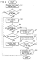
- Fig. 3 is a flow chart explaining a raising operation of the floating-type magnetic head during the stopping of the rotative movement of the magnetic disk in the magnetic disk device of Fig. 1.
- Fig. 4 is a flow chart explaining a raising operation of the floating-type magnetic head in the case where the rotating speed of the magnetic disk is reduced to not more than a predetermined value due to a machine malfunction or the like when the floating-type magnetic head is in close proximity to the magnetic disk.
- Figs. 5 through 10 show the second embodiment of the present invention.
- Fig. 5 is a schematic elevation showing the operation of a raising and lowering member of a magneto-optical disk device that is provided with a floating-type magnetic head.
- Fig. 6 is a schematic side view explaining the behavior of the floating-type magnetic head during its raising and lowering operations in the magneto-optical disk device of Fig. 5.
- Fig. 7 is a schematic front view explaining the behavior of the floating-type magnetic head during its raising and lowering operations in the magneto-optical disk device of Fig. 5.
- Fig. 8 is a schematic elevation showing a magneto-optical disk device that is provided with a floating-type magnetic head.
- Fig. 9 is a schematic plan view showing the floating-type magnetic head in the magneto-optical disk device of Fig. 8.
- Fig. 10 is a schematic side view showing the floating-type magnetic head in the magneto-optical disk device of Fig. 8.
- Figs. 11 through 23 and Figs. 56 through 59 show the third embodiment of the present invention.
- Fig. 11 is a schematic elevation showing the operation of a raising and lowering member of a magneto-optical disk device that is provided with a floating-type magnetic head.
- Fig. 12 is a schematic elevation showing an assembling adjustment of the floating-type magnetic head in the magneto-optical disk device of Fig. 11.
- Fig. 13 is a schematic elevation showing a specific example of a raising and lowering member of the magneto-optical disk device of Fig. 11.
- Fig. 14 is an explanatory drawing which shows possible contact of the floating-type magnetic head against the magneto-optical disk, when it is repeatedly raised and lowered from and toward the magneto-optical disk, by using the relationship between the inclination of the suspension with respect to the magneto-optical disk and the pressing load of the suspension.
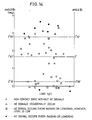
- Fig. 15 is an explanatory drawing which shows possible contact of the floating-type magnetic head against the magneto-optical disk, when it is repeatedly raised and lowered from and toward the magneto-optical disk, by using the relationship between the height of a fixing member and the inclination of the fixing member with respect to the magneto-optical disk.
- Fig. 16 shows waveforms of AE signals that were obtained when the raising and lowering speed of the floating-type magnetic head was set to 11.5 mm/sec in a magneto-optical disk device, which had been assembled under the conditions of P 11 of Fig. 15.
- Fig. 17 shows waveforms of AE signals that were obtained when the raising and lowering speed of the floating-type magnetic head was set to 38 mm/sec in a magneto-optical disk device, which had been assembled under the conditions of P 11 of Fig. 15.
- Fig. 18 shows waveforms of AE signals that were obtained when the raising and lowering speed of the floating-type magnetic head was set to 11.5 mm/sec in a magneto-optical disk device, which had been assembled under the conditions of P 12 of Fig. 15.
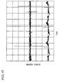
- Fig. 19 shows waveforms of AE signals that were obtained when the raising and lowering speed of the floating-type magnetic head was set to 4.8 mm/sec in a magneto-optical disk device, which had been assembled under the conditions of P 12 of Fig. 15.
- Fig. 20 shows waveforms of AE signals that were obtained when the raising and lowering speed of the floating-type magnetic head was set to 11.5 mm/sec in a magneto-optical disk device, which had been assembled under the conditions of P 13 of Fig. 15.
- Fig. 21 shows waveforms of AE signals that were obtained when the raising and lowering speed of the floating-type magnetic head was set to 4.8 mm/sec in a magneto-optical disk device, which had been assembled under the conditions of P 13 of Fig. 15.
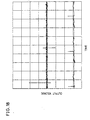
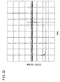
- Fig. 22 shows waveforms of AE signals that were obtained when the raising and lowering speed of the floating-type magnetic head was set to 9.2 mm/sec in a magneto-optical disk device, which had been assembled under the conditions of P 13 of Fig. 15.
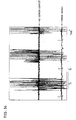
- Fig. 23 shows waveforms of AE signals that were obtained when the raising and lowering speed of the floating-type magnetic head was set to 11.5 mm/sec in a magneto-optical disk device, which had been assembled under the conditions of P 14 of Fig. 15.
- Figs. 56 and 57 are explanatory drawings which show possible contact of the floating-type magnetic head against the magneto-optical disk, when it is repeatedly raised and lowered from and toward the magneto-optical disk, by using the relationship between the inclination of the suspension with respect to the magneto-optical disk and the inclination of the fixing member.
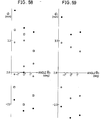
- Figs. 58 and 59 are explanatory drawings which show possible contact of the floating-type magnetic head against the magneto-optical disk, when it is repeatedly raised and lowered from and toward the magneto-optical disk, by using the relationship between the height of a fixing member and the inclination of the fixing member with respect to the magneto-optical disk.
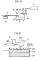
- Fig. 24 is a schematic elevation showing a magneto-optical disk device that is provided with a floating-type magnetic head, and illustrates the fourth embodiment of the present invention.
- Figs. 25 through 28 show the fifth embodiment of the present invention.
- Fig. 25 is a schematic vertical sectional view showing a magneto-optical disk with a floating-type magnetic head.
- Fig. 26 is a schematic front view showing a magneto-optical disk device that is provided with the floating-type magnetic head of Fig. 25.
- Fig. 27 is a schematic side view showing the magneto-optical disk device of Fig. 26.
- Fig. 28 is a graph indicating possible contact of a slider of Fig. 25 against the magneto-optical disk, which was obtained by varying the inclination of the slider and the height of the slider from the surface of the magneto-optical disk when it is released.
- Fig. 29 is a schematic front view showing a magneto-optical disk device that is provided with the floating-type magnetic head, and illustrates the sixth embodiment of the present invention.
- Fig. 30 is a schematic front view showing a magneto-optical disk device that is provided with the floating-type magnetic head, and illustrates the seventh embodiment of the present invention.
- Figs. 31 through 34 show the eighth embodiment of the present invention.
- Fig. 31 is a schematic side view showing a floating-type magnetic head of a magneto-optical disk device.
- Fig. 32 is a schematic plan view showing the floating-type magnetic head of the magneto-optical disk device of Fig. 31.
- Fig. 33 is a waveform drawing showing an AE signal and a timing signal which were obtained when the floating-type magnetic head of Fig. 31 was raised and lowered near a ridge of the magneto-optical disk.
- Fig. 34 is a waveform drawing showing an AE signal and a timing signal which were obtained when a floating-type magnetic head without a bevelled portion in its slider was raised and lowered near a ridge of the magneto-optical disk.
- Figs. 35 and 36 show the ninth embodiment of the present invention.
- Fig. 35 is a schematic side view showing a floating-type magnetic head of a magneto-optical disk device.
- Fig. 36 is an enlarged plan view of the slider of the floating-type magnetic head in the magneto-optical disk device of Fig. 35.
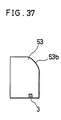
- Fig. 37 is a schematic plan view showing a floating-type magnetic head of a magneto-optical disk device, and illustrates the tenth embodiment of the present invention.
- Figs. 38 through 47 show the eleventh embodiment of the present invention.
- Fig. 38 is a process drawing which shows a loading method of a magneto-optical disk cartridge in a magneto-optical disk device.
- Fig. 39 is a process drawing which shows an unloading method of the magneto-optical disk cartridge in the magneto-optical disk device.
- Fig. 40 is a schematic side view showing a loading process of the magneto-optical disk cartridge of Fig. 38.
- Fig. 41 is a schematic side view showing a rotative accelerating process of a spindle motor and an inserting process of the floating-type magnetic head in the magneto-optical disk cartridge of Fig. 38.
- Fig. 42 is a schematic side view showing a lowering process of the floating-type magnetic head of Fig. 38.
- Fig. 43 is a schematic side view showing a raising process of the floating-type magnetic head of Fig. 38.
- Fig. 44 is a schematic side view showing an accessing process of the floating-type magnetic head of Fig. 38 to a recording position.
- Fig. 45 is a perspective view of the magneto-optical disk cartridge.
- Fig. 46 is a perspective exploded view of the magneto-optical disk cartridge.
- Fig. 47 is a perspective view of a cartridge holder in which the magneto-optical disk cartridge is inserted.
- Figs. 48 through 55 show the prior art.
- Fig. 48 is a schematic side view showing a magneto-optical recording-reproduction apparatus that is provided with a floating-type magnetic head.
- Fig. 49 is a schematic plan view showing the floating-type magnetic head of Fig. 48.
- Fig. 50 is a schematic side view showing a state of the floating-type magnetic head of Fig. 48 when it is located near a ridge that exists along the outer edge area of the magneto-optical disk.
- Fig. 51 is a schematic plan view showing a state of the floating-type magnetic head of Fig. 48 when it is located near a ridge that exists along the outer edge area of the magneto-optical disk.
- Fig. 52 is a graph showing data of measurements with respect to the disk height near a ridge that exists along the outer edge area of a magneto-optical disk.
- Fig. 53 is a graph showing data of measurements with respect to the disk height near a ridge that exists along the outer edge area of another magneto-optical disk.
- Fig. 54 is a graph showing data of measurements with respect to the disk height near a ridge that exists along the outer edge area of still another magneto-optical disk.
- Fig. 55 is a graph showing data of measurements with respect to the disk height near a ridge that exists along the outer edge area of another magneto-optical disk.
- a magnetic disk device of the present embodiment is provided with a floating-type magnetic head 15 located above a magnetic disk 13 (disc-shaped recording medium), a raising and lowering means 16 for raising or lowering the floating-type magnetic head 15 in the vertical direction with respect to the surface of the magnetic disk 13 and a position sensor (position detecting means) for detecting whether the floating-type magnetic head 15 is located in the proximity of the magnetic disk 13 or not.
- the position sensor is not shown in Fig. 1.
- the floating-type magnetic head 15 is constituted of, for example, a magnetic head (not Shown), a slider (not shown) to which the magnetic head is secured.
- the floating-type magnetic head 15 is supported by a suspension (not shown) and pressed toward one surface of the magnetic disk 13 by the suspension.
- the floating-type magnetic head 15 is moved by a driving means such as a linear motor (not shown) in the radial direction of the magnetic disk 13.
- the magnetic disk device also includes a spindle motor 12 (rotative driving means) for rotatively driving the magnetic disk 13, a rotating speed detection means 14 for detecting the rotating speed of the magnetic disk 13, that is, the number of rotations per unit time, and a control section 11 (control means) for controlling raising and lowering operations of the floating-type magnetic head 15 that are be executed by a raising and lowering means 16 and the rotation of the spindle motor 12, based on signals from a position sensor and the rotating speed detection means 14.
- a spindle motor 12 rotative driving means
- a rotating speed detection means 14 for detecting the rotating speed of the magnetic disk 13, that is, the number of rotations per unit time
- control section 11 control means for controlling raising and lowering operations of the floating-type magnetic head 15 that are be executed by a raising and lowering means 16 and the rotation of the spindle motor 12, based on signals from a position sensor and the rotating speed detection means 14.
- a pulse generator which is constituted of a piece of magnet secured to the rotation shaft of the spindle motor 12 and a fixed magnetic head, or a frequency generator is used as the rotating speed detection means 14.
- the floating-type magnetic head 15 while floating above the magnetic disk 13, records information by applying a magnetic field onto the magnetic disk 13 and reproduces information by detecting leakage flux from the magnetic disk 13.
- the optical head is arranged so that it faces the floating-type magnetic head 15 with the magneto-optical disk located in between.
- position-identifying information of the floating-type magnetic head 15, which is detected by the position sensor, is read by the control section 11 in order to check to see whether or not the floating-type magnetic head 15 is located at a position (height) where information recording or reproducing is operable with respect to the magnetic disk 13, that is, whether or not the floating-type magnetic head 15 is in close proximity (in a floating state) to the magnetic disk 13.
- rotating speed information of the magnetic disk 13 is read from the rotating speed detection means 14 by the control section 11 in order to check to see a rotation condition of the magnetic disk 13 (S3).
- control section 11 it is recognized whether or not the magnetic disk 13 is rotating at not less than a predetermined rotating speed, based on the rotating speed information (S4).
- the control section 11 determines whether or not the magnetic disk 13 is in stoppage (S5). If the magnetic disk 13 is in stoppage, the control section 11 permits the spindle motor 12 to rotate (S6). Then, the sequence is returned to S3. If the magnetic disk 13 is in motion, the sequence is returned to S3, and the steps S3 to S5 are repeated until the magnetic disk 13 has reached the predetermined rotating speed.
- the control section 11 allows the raising and lowering means 16 to start lowering the floating-type magnetic head 15 such that the floating-type magnetic head 15 is gradually brought closer to the magnetic disk 13 (S7). Then, position-identifying information of the floating-type magnetic head 15, which is detected by the position sensor, is read by the control section 11 in order to check to see whether or not the floating-type magnetic head 15 is in close proximity to the magnetic disk 13 (S8).
- the control section 11 it is recognized in the control section 11 whether or not the floating-type magnetic head 15 is in close proximity to the magnetic disk 13 (S9).
- control section 11 allows the raising and lowering means 16 to stop lowering the floating-type magnetic head 15 (S10), and thus the lowering operation is completed.
- the sequence is returned to S8, and the steps S8 to S9 are repeated until the floating-type magnetic head 15 has brought in close proximity to the magnetic disk 13.
- the magnetic disk device of the present embodiment is arranged such that after the floating-type magnetic head 15 has reached a predetermined rotating speed, the floating-type magnetic head 15 is brought closer to the magnetic disk 13; therefore, the floating-type magnetic head 15 is inevitably subject to a predetermined floating force produced by the rotation of the magnetic disk 13.
- accidental contact of the floating-type magnetic head 15 with the magnetic disk 13 can be virtually eliminated. Therefore, damage to the floating-type magnetic head 15 or the magnetic disk 13 and sticking of the floating-type magnetic head 15 to the magnetic disk 13 can be prevented.
- the floating-type magnetic head 15 is accurately lowered by the closed loop control.
- position-identifying information of the floating-type magnetic head 15, which is detected by the position sensor, is read by the control section 11 in order to check to see whether or not the floating-type magnetic head 15 is located at a position where information recording or reproducing is operable with respect to the magnetic disk 13, that is, whether or not the floating-type magnetic head 15 is in close proximity to the magnetic disk 13 (S11).
- control section 11 stops the rotation of the magnetic disk 13 by shutting off the spindle motor 12 (S17), thereby terminating the sequence.
- control section 11 permits the raising and lowering means 16 to start raising the floating-type magnetic head 15 so as to move the floating-type magnetic head 15 away from the magnetic disk 13 (S13). Then, position-identifying information of the floating-type magnetic head 15, which is detected by the position sensor, is again read by the control section 11 in order to check to see whether or not the floating-type magnetic head 15 is in close proximity to the magnetic disk 13 (S14).
- the sequence is returned to S4. Then, the steps S4 to S5 are repeated until the floating-type magnetic head 15 has been brought to a position that is no longer in close proximity to the magnetic disk 13, that is, a position having not less than a predetermined gap from the magnetic disk 13.
- control section 11 After the floating-type magnetic head has been brought not less than a predetermined space away from the magnetic disk 13, the control section 11 allows the raising and lowering means 16 to stop raising the floating-type magnetic head 15 (S16). The control section 11 stops the rotation of the magnetic disk 13 by shutting off the spindle motor 12 (S17), thereby terminating the sequence.
- the magnetic disk device of the present embodiment is arranged such that after the magnetic disk 13 has been separated away from the magnetic disk 13, the spindle motor 12 is shut off to stop the rotation of the magnetic disk 13; therefore, on stopping rotative driving of the magnetic disk 13, accidental contact of the floating-type magnetic head 15 with the magnetic disk 13 can be virtually eliminated. Thus, damage to the floating-type magnetic head 15 or the magnetic disk 13 and sticking of the floating-type magnetic head 15 to the magnetic disk 13 can be prevented.
- the control section 11 constantly reads rotating speed information of the magnetic disk 13 from the rotating speed detection means 14 by interruption processing or the like, in order to check to see the rotation condition of the magnetic disk 13 (S21). Thus, the control section 11 always recognizes whether or not the magnetic disk 13 is rotating at not less than a predetermined rotating speed (S22).
- the sequence is terminated without executing any step.
- the control section 11 at once permits the raising and lowering means 16 to start raising the floating-type magnetic head 15, and the floating-type magnetic head 15 is moved away from the magnetic disk 13 (S23).
- position-identifying information of the floating-type magnetic head 15, which is detected by the position sensor, is read by the control section 11 in order to check to see whether or not the floating-type magnetic head 15 is in close proximity to the magnetic disk 13 (S24). According to this position-identifying information, the control section 11 recognizes whether or not the floating-type magnetic head 15 is in close proximity to the magnetic disk 13 (S25).
- the sequence is returned to S24. Then, the steps S24 to S25 are repeated until the floating-type magnetic head 15 has been brought to a position that is no longer in close proximity to the magnetic disk 13.
- control section 11 After the floating-type magnetic head 15 has been brought to the position that is no longer in close proximity to the magnetic disk 13, the control section 11 allows the raising and lowering means 16 to stop raising the floating-type magnetic head 15 (S26), thereby terminating the sequence.
- the magnetic disk device of the present embodiment is arranged such that, when the floating-type magnetic head 15 is in close proximity to the magnetic disk 13, the rotation condition of the magnetic disk 13 is constantly checked and, if the rotating speed of the magnetic disk 13 becomes not more than a predetermined value due to a certain reason, the floating-type magnetic head 15 is at once moved away from the magnetic disk 13.
- the position sensor for detecting whether or not the floating-type magnetic head 15 is in close proximity to the magnetic disk 13 is provided, it becomes possible to accurately recognize the fact that the floating-type magnetic head 15 is separated away from the magnetic disk 13.
- the present invention is also applicable to information reproducing-reproduction apparatuses such as magneto-optical disk devices. Further, the present invention is applicable not only to the floating-type magnetic head 15 but also to various floating-type heads such as floating-type optical heads.
- a magnetic disk device of the present embodiment is provided with a spindle motor 12 for rotatively driving a magneto-optical disk 21 (disc-shaped recording medium), an optical head 24, located facing one surface of the magneto-optical disk 21 (bottom surface in the drawing), for projecting a light beam onto the magneto-optical disk 21 through an objective lens 23 as well as for conducting reproduction of information or other operation according to light reflected off from the magneto-optical disk 21, and a floating-type magnetic head 15, located at such a position on the other surface of the magneto-optical disk 21 (top surface in the drawing) as operable with the objective lens 23, for applying a magnetic field onto the magneto-optical disk 21.
- the optical head 24 is moved by a driving means such as a linear motor (not shown) in the radial direction of the magneto-optical disk 21.
- a suspension 26 composed of plate springs is secured to the horizontal face of a fixing member 27, and the floating-type magnetic head 15 is supported by the other end of the suspension 26.
- the fixing member 27 is moved in the radial direction of the magneto-optical disk 21 by a shifting means that is different from the shifting means for the optical head 24.
- the suspension 26 is made of stainless steel with a thickness of substantially 70 ⁇ m, and the width of the suspension 26 narrows from the base to the end where the floating-type magnetic head 15 is located.
- the length l 1 of the suspension 26 (the distance from the center of a slider 30 of the floating-type magnetic head 15 to the center of a metal plate 28) is 26.41 mm.
- the metal plate 28 is welded to the wider end of the suspension 26 to form a connecting section to the fixing member 27.
- the size of the metal plate 28 is 6 mm wide in the radial direction of the magneto-optical disk 21, 10.2 mm long in the circumferential direction of the magneto-optical disk 21, and 0.5 mm thick.
- a magnetic head 31 is fixed to one corner of the slider 30, which corner is located at the outer side of the magneto-optical disk 21.
- the length w 1 of the slider 30 in the radial direction of the magneto-optical disk 21 is 5 mm; the length w 2 in the circumferential direction is 7 mm; the whole thickness t 1 of the slider 30 is 2 mm; and the thickness t 2 from the surface facing the magneto-optical disk 21 to the face whereto the suspension 26 is bonded is 0.82 mm.
- the bottom surface of the floating-type magnetic head 15, that is, the surface of the floating-type magnetic head 15 facing the magneto-optical disk 21, has a sloped portion (with an angle of inclination of, for example, 0.5°) with a width of substantially 1 mm in the circumferential direction of the magneto-optical disk 21 at the edge portion from which air flows in by the rotation of the magneto-optical disk 21.
- the suspension 26 is less flexible at an area 26a where the flanges 32 are formed than at the other area 26b where the flanges 32 are not formed.
- the length of the area 26b is determined so that the floating-type magnetic head 15 can be pressed toward magneto-optical disk 21 at 1 to 10 gf, and in the present embodiment, it is set to 3 to 5 mm.
- the angle ⁇ 4 made by the bottom surface and the suspension 26 is conventionally set to 2.2° while the distance d 1 ' between the bottom surface and the top surface of the metal plate 28 is set to 2.54 mm.
- a first raising and lowering member 33 is provided below the suspension 26 and, by contacting it at the area 26a from under, supports the suspension 26 so as to permit it to freely move upward or downward.
- a second raising and lowering member 34 is disposed below the fixing member 27 and, by contacting it from under, supports the fixing member 27 so as to permit it to freely move upward or downward.
- the raising and lowering members 33 and 34 are simultaneously raised or lowered.
- the raising and lowering members 33 and 34 are positioned at level A in Fig. 5 above the magneto-optical disk 21 such that the floating-type magnetic head 15 is kept away from the surface of the magneto-optical disk 21 during the stoppage of the rotation of the magneto-optical disk 21.
- the raising and lowering members 33 and 34 move downward to lower the floating-type magnetic head 15 toward the magneto-optical disk 21. At this time, the relationship of levels among the floating-type magnetic head 15, the suspension 26 and the fixing member 27 is maintained constant.
- inclination of the floating-type magnetic head 15 is adjusted so that during the lowering operation of the floating-type magnetic head 15, as shown in Fig. 6, the angle ⁇ 1 made by the magneto-optical disk 21 and the floating-type magnetic head 15 in the radial direction substantially becomes 0° while, as shown in Fig. 7, the angle ⁇ 2 made by the magneto-optical disk 21 and the floating-type magnetic head 15 in the circumferential direction also substantially becomes 0°.
- the lowering operation of the fixing member 27 is stopped, and then the fixing member 27 is moved only in the radial direction of the magneto-optical disk 21.
- the raising and lowering member 33 and 34 are further lowered from the level B to level C.
- the floating-type magnetic head 15 is permitted to float above the surface of the magneto-optical disk 15 with a predetermined gap in between.
- the raising and lowering members 33 and 34 while following reversed steps to those of the above-mentioned, are raised from the level C and contact the suspension 26 and the fixing member 27 at the level B. Further, when the raising and lowering members 33 and 34 are raised to the level A, the floating-type magnetic head 15 is maintained in the position away from the magneto-optical disk 21. Then, the rotation of the magneto-optical disk 21 is stopped.
- the floating-type magnetic head 15 is lowered with the bottom surface kept substantially parallel to the surface of the magneto-optical disk 21; therefore, when the raising and lowering member 33 is moved away from the suspension 26 and thus the floating-type magnetic head 15 starts floating by receiving air pressure, accidental contact of the floating-type magnetic head 15 with the magneto-optical disk 21 can be minimized.
- the fixing member 27 is raised and lowered by the raising and lowering member 34, another shifting means that is different from the shifting means for the optical head 24 is needed for shifting the fixing member 27 in the radial direction of the magneto-optical disk 21.
- another arrangement may be adopted, wherein the fixing member 27 is removably coupled to the shifting member for the optical head 24 by a coupling means.
- a magneto-optical disk device of the present embodiment is different from that of the second embodiment in that the fixing member 27 is positioned at a fixed level.
- a raising and lowering member 35 is arranged to come into contact with the area 26a (see Fig. 10) of the suspension 26 from under, and thus the area 26b of the suspension 26 is elastically deformed by raising and lowering operations of the raising and lowering member 35 between the levels A and C. With this arrangement, the floating-type magnetic head 15 can be raised and lowered with respect to the magneto-optical disk 21.
- inclination of the floating-type magnetic head 15 is adjusted so that the bottom surface of the floating-type magnetic head 15 is kept substantially parallel to the surface of the magneto-optical disk 21 when the floating-type magnetic head 15 is lowered and the raising and lowering member 35 is separated from the suspension 26 at the level B.
- the floating-type magnetic head 15 can be shifted in the radial direction of the magneto-optical disk 21 by the use of the shifting means for the optical head 24.
- the position of the floating-type magnetic head 15 was adjusted by varying d 1 and the angle ⁇ 3 of the fixing member 27 with respect to the radial direction. Further, the angle ⁇ 2 with respect to the circumferential direction (see Fig. 7) was substantially set to 0° by keeping horizontal the inclination of the fixing member 27 with respect to circumferential direction.
- the magneto-optical disk 21 rotated 3000 rpm.
- the floating-type magnetic head 15 was repeatedly raised and lowered at a position 33 mm away from the center of the magneto-optical disk 21 in the radial direction.
- the speed of the raising and lowering operations of the floating-type magnetic head 15 was set to 11.5 mm/s in both the raising and lowering operations. Each of the raising and lowering operations was conducted every two seconds.
- a lever 40 which was pivotally supported by a shaft on the fixing member 27, was used as the raising and lowering member 35.
- One end of the lever 40 was adapted to contact the suspension 26 from under, while the other end of the lever 40 is moved upward and downward by a driving device 41.
- the suspension 26 is moved upward and downward by the end of the lever 40.
- Figs. 14 and 15 The experimental results are shown in Figs. 14 and 15.
- open circles represent that no AE signals were detected, while triangles represent that AE signals were occasionally detected.
- open squares represent that, although an AE signal was always detected in either raising or lowering operation of the floating-type magnetic head 15, the level of the signal was comparatively low.
- solid squares represent that AE signals were detected every time in both raising and lowering operations.
- the height d 1 and the angle ⁇ 3 of the fixing member 27 were varied in order to adjust the position of the floating-type magnetic head 15 (see Fig. 12). Then, after actually measuring a pressing load of the floating-type magnetic head toward the magneto-optical disk 21 in each position, possible contact therebetween was examined by repeatedly conducting raising and lowering operations.
- a reflective section 36 was formed at the area 26a of the suspension 26; (for example, a reflective tape was affixed thereto), and a light beam was applied onto the reflective section 36 perpendicularly from under.
- a laser light source 37 was placed behind a screen 38, and the light beam, which had passed through a fine hole 39 that was made in the screen 38, was reflected off from the reflective section 36 to produce a light spot Sp on the screen 38.
- the floating-type magnetic head 15 can be raised and lowered without contacting the magneto-optical disk 21 if the value of ⁇ 4 is set within 0° 15' to 2° 50'. Therefore, in adjusting the position of the floating-type magnetic head 15, if the setting value of ⁇ 4 is kept within 1° 35' to 1° 40', the tolerances of ⁇ 1° 10' can be obtained.
- Fig. 15 shows the experimental results that are plotted with respect to ⁇ 3 and d 1 .
- non-contact area there is an area where no contact occurs (non-contact area), which has a belt-like shape going diagonally down to the right with a width of substantially 1 mm in d 1 .
- the raising and lowering operations of the floating-type magnetic head 15 were repeatedly conducted ten thousand times with respect to a magneto-optical disk 21 that was made of a polycarbonate substrate.
- the other experimental conditions were the same as those employed in the aforementioned magneto-optical disk 21 that was made of the glass substrate.
- the position adjustment of the floating-type magnetic head 15 can be performed accurately by adjusting ⁇ 3 and d 1 while the angle ⁇ 4 between the suspension 26 and the magneto-optical disk 21 is being detected by reflecting the light beam off from the reflective section 36.
- the variation of ⁇ x becomes greater even if the variation of ⁇ 4 created by adjusting d 1 and ⁇ 3 is slight; therefore, the variation of ⁇ 4 can be detected with high sensitivity.
- the fixing member 27 is secured when ⁇ x has substantially approached the target value, thereby completing the adjustment.
- waveforms shown below represent AE signals, while those shown above are timing signals.
- the horizontal axis represents time.
- the timing signal contains pulses which occur when the floating-type magnetic head 15 is raised. Accordingly, an AE signal observed before the pulse indicates that a contact has occurred in a raising operation of the floating-type magnetic head 15, and on the other hand an AE signal observed after the pulse indicates that a contact has occurred in a lowering operation of the floating-type magnetic head 15.
- the waveforms shown in Fig. 16 were obtained when the raising and lowering speed of the floating-type magnetic head 15 was set to 11.5 mm/sec in a magneto-optical disk device, which had been assembled under the conditions of P 11 .
- the AE signals appear after the pulses of the timing signal; therefore, contact occurs in the lowering operation of the floating-type magnetic head 15. Further, although the cases are rare, contact also occurs in the raising operation.
- the waveforms shown in Fig. 17 were obtained when the raising and lowering speed of the floating-type magnetic head 15 was set to 38 mm/sec in the magneto-optical disk device, which had been assembled under the conditions of P 11 .
- the levels of the AE signals in the raising operations of the floating-type magnetic head 15 become greater and the levels of the AE signals in the lowering operations also become remarkably greater, which shows that impacts upon contacting are considerably great.
- the behavior of the floating-type magnetic head 15 was checked by applying a light beam onto a gliding surface of the slider 30 of the floating-type magnetic head 15 according to the setting of Fig. 12. Then, by observing the movements of the light spot on the screen 38, it was found that the floating-type magnetic head 15 was violently shaking during the raising operation as well as the lowering operation.
- an AE signal with high level occurred in every raising operation of the floating-type magnetic head 15.
- the slider 30 shook violently, and the shaking remained in the following lowering operations, causing the AE signals to become great also in the lowering operations.
- the AE signal did not occur, or, even if it occurred, the level was low.
- the waveform shown in Fig. 20 was obtained when the raising and lowering speed of the floating-type magnetic head 15 was set to 11.5 mm/sec for use in a magneto-optical disk device, which had been assembled under the conditions of P 13 .
- the timing signal was not recorded, the positions of the pulses were shown with "cross mark".
- an AE signal occurred in every lowering operation of the floating-type magnetic head 15. In raising operations, AE signals occurred only occasionally.
- the waveforms shown in Fig. 21 were obtained when the raising and lowering speed of the floating-type magnetic head 15 was set to 4.8 mm/sec for use in the magneto-optical disk device, which had been assembled under the conditions of P 13 .
- the waveforms shown in Fig. 22 were obtained when the raising and lowering speed of the floating-type magnetic head 15 was set to 9.2 mm/sec for use in the magneto-optical disk device, which had been assembled under the conditions of P 13 . AE signals appeared in the lowering operations of the floating-type magnetic head 15.
- the waveforms shown in Fig. 23 were obtained when the raising and lowering speed of the floating-type magnetic head 15 was set to 11.5 mm/sec for use in a magneto-optical disk device, which had been assembled under the conditions of P 14 .
- AE signals with low level occasionally occurred in the lowering operations of the floating-type magnetic head 15.
- the raising speed of the floating-type magnetic head 15 is desirably set to not less than 12 mm/sec.
- the magneto-optical disk device of the present embodiment it is desirable to drive the raising and lowering lever 40 by means of the driving device 41 so that the lowering speed may be set to not more than 10 mm/sec, when the floating-type magnetic head 15 is shifted to the floating position above the magneto-optical disk 21 in rotation, and so that the raising speed may be set to not less than 15 mm/sec, more preferably to not less than 12 mm/sec, when the floating-type magnetic head 15 is shifted away from the magneto-optical disk 21.
- the tolerance range of ⁇ 3 and d 1 can be expanded, the allowable gap for avoiding contact between the floating-type magnetic head 15 and the magneto-optical disk 21 can be widened. That is to say, during assembling processes, the position adjustment of the magneto-optical disk device can be easily executed.
- a magneto-optical disk device of the present embodiment is different from that of the third embodiment in that a driving device 43 for raising and lowering the lever 40 and a spring 42 for slowing down the lowering speed of the lever 40 compared with the raising speed, are separately installed.
- the driving device 43 permits the raising and lowering lever 40 to provide a constant raising and lowering speed of the floating-type magnetic head 15.
- the lever 40 comes into contact with the spring 42 on the way of descending.
- a force which is obtained by subtracting a spring force of the spring 42 from the driving force of the driving device 43, is applied onto the lever 40.
- the lowering speed of the floating-type magnetic head 15 is decreased.
- the magnetic head 15 is raised, the raising speed is increased with the receipt of the spring force from the spring 42.
- a magneto-optical disk device of the present embodiment is different from that of the aforementioned embodiments in that the floating-type magnetic head 15 is raised in such a position that an inclined portion 30b of the slider 30 (an end from which air flows in) is kept slightly higher than the other portion, that is, ⁇ 2 is kept on the order of 1°.
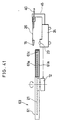
- the magneto-optical disk device is provided with an optical head 24, an arm 45 for supporting a suspension 26, which is roughly U-shaped and secured to the optical head 24 at the lower end thereof, and the suspension 26 which, together with a metal plate 28, is fixed to a fixing section 27 of the upper end of the arm 45.
- the end portion 26a of the suspension 26 is fixed to a grooved portion 30a provided on the upper part of the slider 30.
- the inclined portion 30b is formed in the bottom surface of the slider 30 at the front portion thereof, when seen from the rotation direction of the magneto-optical disk 21.
- the inclined portion 30b is followed by a flat portion 30c.
- a magnetic head 31 is installed at the rear portion of the slider 30, when seen from the rotation direction of the magneto-optical disk 21.
- a lever 40 which is roughly L-shaped and has a supporting portion 40a extending in substantially parallel with the surface of the magneto-optical disk 21, is freely pivotally supported to the arm 45 at the fixing section 27 by a machine screw 46.
- a projecting section 40b at the end of the supporting portion 40a is adapted to come into contact with the bottom surface of the suspension 26.
- the suspension 26 By pivoting the lever 40 on the machine screw 46 as a fulcrum, with the projecting section 40b contacting the bottom surface of the suspension 26, the suspension 26 is pivoted upward, thereby raising the slider 30 upward.
- the slider 30 can be maintained at a position where no contact occurs against the magneto-optical disk 21.
- the projecting section 40b contacts the bottom surface of the suspension 26 at a position that departs from the center line L-L, drawn in the lengthwise direction of the suspension 26, toward the inclined portion 30b of the slider 30; therefore, as shown in Fig. 25, when the lever 40 lifts the slider 30 by way of the suspension 26, the slider 30 is raised in the position such that the end from which air flows in is kept slightly higher than the other portion.
- the inclination ⁇ 2 of the flat portion 30c is preferably set to be on the order of 1°.
- the magneto-optical disk 21 is constituted of, for example, a substrate 21a made of glass or a transparent resin such as polycarbonate, a magneto-optical recording medium 21b made of a rare earth-transition metal alloy thin film or the like, and a protective film 21c.
- a resin such as SD 301 manufactured by Dainippon Ink And Chemicals, Incorporated may be employed.
- the magneto-optical disk 21 When recordings are to be made on the magneto-optical disk 21, the magneto-optical disk 21 is rotated by the spindle motor 12 (see Fig. 13) and, after the rotating speed of the magneto-optical disk 21 has reached a predetermined value, the lever 40 is pivoted upward. Thus, the slider 30 is released with a small gap from the magneto-optical disk 21.
- the projecting section 40b has contacted the bottom surface of the suspension 26 at the position that departs from the center line L-L of the suspension 26 toward the inclined portion 30b, and thereby the slider 30 has been maintained in the position wherein the inclined portion 30b is kept slightly higher than the other portion; therefore, when released, the slider 30 receives a great floating pressure upon the whole flat portion 30c and floats above the magneto-optical disk 21 without contacting the surface of the magneto-optical disk 21.
- a magnetic field that is inverted according to information to be recorded is applied from the magnetic head 31 onto the magneto-optical disk 21 at the same time that a light beam is projected from the optical head 24 onto the magneto-optical disk 21, thereby permitting the information to be magneto-optically recorded on the magneto-optical recording medium 21b.
- the lever 40 is again pivoted downward such that the slider 30 is raised through the suspension 26 and maintained at a level away from the magneto-optical disk 21, and then the rotation of the magneto-optical disk 21 is stopped.
- a light beam is projected from the optical head 24 onto the magneto-optical disk 21, and by detecting the rotation of the polarization plane in the light reflected therefrom, the information is optically reproduced.
- the slider may be constantly kept in the lifted state, for example, by means of the lever 40 through the suspension 26.
- a range of [d 1 (the height from the bottom surface of the slider 30 to the fixing section 27) - 2.54 mm], wherein the slider 30 can be raised and lowered without contact, is indicated in Fig. 28.
- the plus region in the horizontal axis represents that the flat portion 30c is inclined with the inclined portion 30b side higher than the magnetic head side, while the minus region therein represents that the flat portion 30c is inclined with the inclined portion 30b side lower than the magnetic head side.
- open circles indicate the cases where, when released, the slider 30 is able to float above the magneto-optical disk 21 without contacting it.
- Solid circles indicate the cases where, when the slider 30 is released, contact occurs between the slider 30 and the magneto-optical disk 21 before the slider starts floating and comes into a stable floating state above the surface of the magneto-optical disk 21.
- the conditions under which the slider 30 can be floated without contact are much more alleviated; and this results in an advantage that the mechanical design of the magneto-optical disk device equipped with the floating-type magnetic head 15 can be easily made.
- a magneto-optical disk device of the present embodiment is different from that of the fifth embodiment in that the supporting portion 40a of the lever 40 is inclined by approximately 1° with respect to the surface of the magneto-optical disk 21 so as to keep the inclined portion 30b side of the slider 30 higher than the other side thereof.
- the present embodiment is to give one example of the slider 30 wherein an inclined position of the slider 30 is achieved by devising the shape of the lever 40. Therefore, any shape of the lever 40 other than the one shown in Fig. 29 may be adopted as long as the slider 30 is maintained in the position such that the inclined portion 30b side is higher than the other side.
- a magneto-optical disk device of the present embodiment is different from that of the sixth embodiment in that the fixing member 27 of the arm 45 is inclined so as to keep the inclined portion 30b side of the slider 30 higher than the other side thereof.
- the slider 30 when the slider 30 is held by the lever 40 (not shown) through the suspension 26 (for example, in an horizontal position), the slider 30 is maintained in such a position that the inclined portion 30b side is higher than the other side.
- the present embodiment is to give one example of the arrangement wherein an inclined position of the slider 30 can be achieved by inclining the base of the suspension 26. Therefore, another method such as to dispose an inclined spacer onto the fixing member 27 may be adopted in order to incline the base of the suspension 26.
- a magneto-optical disk device of the present embodiment is different from that of the aforementioned embodiments in that a bevelled portion 51a is provided in the bottom surface of the slider 51 at the corner that faces the outer edge of the magneto-optical disk 21 in the floating-type magnetic head 15.
- the floating-type magnetic head 15 is provided with the slider 51 and a magnetic head 31 (shown by hatching for convenience) that is secured to the rear end portion of the slider 51, when seen from the rotation direction of the magneto-optical disk 21.
- the floating-type magnetic head 15, which is supported by the suspension 26 while receiving a force on the order of several grams toward the magneto-optical disk 21, is designed to float above the surface of the magneto-optical disk 21 with a gap of several ⁇ m as the magneto-optical disk 21 rotates (at a rotating speed of, for example, 1800 to 4000 rpm.)
- the magneto-optical disk 21 is constituted of a substrate (for example, made of polycarbonate), a vertically magnetized film formed on the substrate, and a protective film made of resin which covers the vertically magnetized film. There exists a ridge 21d along the outer edge of the magneto-optical disk 21.
- the corner between the bottom surface of the slider 51 and the side thereof facing the ridge 21d is chamfered such as to form the inclining bevelled portion 51a.
- Fig. 33 shows the experimental results.
- waveforms shown above represent AE signals, while those shown below are timing signals.
- the bottom surface area of the slider 51 is slightly decreased; however, it is assured as a result of computer simulations that a sufficient floating gap can be obtained.
- the floating gap without the bevelled portion 51a was 5 ⁇ m while the floating gap with the bevelled portion 51a was 4.8 ⁇ m.
- a magneto-optical disk device of the present embodiment is different from that of the eighth embodiment in that, in the floating-type magnetic head 15, a straight bevelled portion 52a is formed in a slider 52 at the front corner that is closer to the outer edge of the magneto-optical disk 21.
- the floating-type magnetic head 15 is provided with the slider 52 and the magnetic head 31 (indicated by hatching for convenience) that is secured to the rear end of the slider 52, when seen from the rotation direction of the magneto-optical disk 21. Since contact between the floating-type magnetic head 15 and the ridge 21d of the magneto-optical disk 21 tends to occur at the front corner of the slider 52 that is closer to the outer edge of the magneto-optical disk 21, the bevelled portion 52a is formed in this corner.
- a magneto-optical disk device of the present embodiment is different from that of the aforementioned embodiments in that, in the floating-type magnetic head 15, a rounded bevelled portion 53a is formed in a slider 53 at the front corner thereof that is closer to the outer edge of the magneto-optical disk 21.
- a magneto-optical disk device of the present embodiment is different from those of the aforementioned embodiments in that a 3.5-inch magneto-optical disk cartridge is employed for use therein.
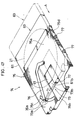
- the magneto-optical disk 21 is placed into a case 61 of the magneto-optical disk cartridge 63. Openings 61a are formed in the top face and the bottom face of the case 61. In the case where the magneto-optical disk cartridge 63 is inserted into the magneto-optical disk device in a direction A (see Fig. 45), the openings 61a are formed in the end face of the case 61 at the inserting side.
- a bridge section 61c is installed in the openings 61a with a view to increasing the strength of the case 61. Further, a groove 61d is formed in the end face at the inserting side, beside the openings 61a. As a sliding member 73 slides along the groove 61d, a shutter 72, which is provided as an integral part of the sliding member 73, is opened and closed.
- the sliding member 73 is constituted by a fitting section 73c, which slides inside the groove 61d, an engaging section 73a, which slides along the wall of the groove 61d with the wall sandwiched between the fitting section 73c and itself, and a connecting section 73b for connecting the engaging section 73a and the fitting section 73c to the shutter 72, and all these sections are integrally formed.
- the width h 1 of the bridge section 61c and the width h 2 of the connecting section 73b are set to, for example, approximately 2 mm.
- a cartridge holder 74 which is provided in the magneto-optical disk device, has a holder frame 75 into which the magneto-optical disk cartridge 63 is inserted.
- Guiding pins 77 for positioning the inserted magneto-optical disk cartridge 63 are attached to a side face 75d of the holder frame 75. Further, the holder frame 75 has an opening 75b that is formed so as to match the opening 61a of the magneto-optical disk cartridge 63 which is to be inserted in the direction A.
- a guiding slit 75c is formed in such a manner that the sliding member 73 can be moved in the direction orthogonal to the inserting direction of the magneto-optical disk cartridge 63, which mechanism will be described later.
- An arm 76 is pivotally supported near the center of the top face of the holder frame 75, and a pin 76a is attached to the pivotal end of the arm 76 in such a manner as to project inside the guiding slit 75c.
- the magneto-optical disk cartridge 63 together with the cartridge holder 74, is drawn into the magneto-optical disk device. Then, the cartridge holder 74 is lowered such that the magneto-optical disk 21 is chucked by the spindle motor 12 (see Fig. 41).
- the optical head 24 and the floating-type magnetic head 15 connected to the optical head 24 are located at a stand-by position where they are free from contacting with the incoming magneto-optical disk cartridge 63.
- the shutter 72 is fully opened, as described earlier.
- the magneto-optical disk 21 is exposed through the openings 61a.
- the cartridge holder 74 is lowered, and the magneto-optical disk 21 is chucked by the spindle motor 12.
- the magneto-optical disk 21 is rotatively driven by the spindle motor 12.
- the floating-type magnetic head 15 and the optical head 24, as shown in Fig. 42 are moved to a predetermined radial position (hereinafter, referred to as descent position).
- descent position a predetermined radial position
- the floating-type magnetic head 15 is lowered through the openings 61a toward the magneto-optical disk 21 by the pivotal movement of the lever 40, and thus floats above the magneto-optical disk 21 without contacting it.
- the descent position is set to be located near the outermost track of the magneto-optical disk 21 so that the floating-type magnetic head 15 can receive the greatest lift from the air flow. This results in the most stable floating state of the floating-type magnetic head 15.
- the floating-type magnetic head 15 and the optical head 24 are moved to a desired access position on the magneto-optical disk 21 by the linear motor (not shown). Additionally, a driving means for moving the floating-type magnetic head 15 and the optical head 24 from the stand-by position to the descent position is installed as a separate means different from the above-mentioned linear motor.
- Fig. 38 and Figs. 40 through 44 the following description will discuss the loading method of the magneto-optical disk cartridge 63 more specifically. Additionally, in Figs. 40 through 44, although the cartridge holder 74 is not illustrated, it is assumed that, in practice, the magneto-optical disk cartridge 63 is placed inside the cartridge holder 74.
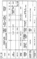
- a period of time, t 0 - t 4 is referred to as an inserting period of the magneto-optical disk cartridge 63; a period of time, t 4 - t 7 , is referred to as an accelerating period of the rotation by the spindle motor 12; a period of time, t 7 - t 8 is referred to as a moving period of the floating-type magnetic head 15 from the stand-by position to the descent position; a period of time, t 8 - t 10 , is referred to as a descending period of the floating-type magnetic head 15; and finally a period of time, t 10 and thereafter, is referred to as a floating period of the floating-type magnetic head 15.
- the floating-type magnetic head 15 and the optical head 24 are held at the stand-by position with a distance of, for example, 55 mm between the central axis of an objective lens 23 and the central axis of the spindle motor 12.
- the floating-type magnetic head 15 remains raised by the lever 40, (where in the case of the distance, 55 mm, between the central axis of an objective lens 23 and the central axis of the spindle motor 12, the central axis position of the objective lens 23 is hereinafter indicated by R55.)
- the magneto-optical disk cartridge 63 is inserted into the cartridge holder 74 that is attached to the inside of the magneto-optical disk device.
- the engaging section 73a of the sliding member 73 attached to the case 61 comes into contact with the pin 76a of the arm 76 that is attached to the holder frame 75 (see Fig. 47).
- the shutter 72 is opened, and the openings 61a are fully opened.
- the cartridge holder 74 containing the magneto-optical disk cartridge 63 is to be drawn into the device.
- the cartridge holder 74 which has reached an engaging position with the spindle motor 12, is gradually lowered.
- the chucking of the magneto-optical disk 21 onto the spindle motor 12 has been completed, and a signal indicating that the magneto-optical disk 21 has been placed on the predetermined station is released from, for example, a sensor.
- the spindle motor 12 starts rotating from the time t 5 , which substantially coincides with the time t 4 , and continues to accelerate until the time t 7 .
- the magneto-optical disk 21 remains placed on the spindle motor 12.
- the floating-type magnetic head 15 and the optical head 24 start moving toward a descent position (for example, R40) that is the outermost position within the operative range at the time t 6 that is slightly before the time t 7 when the spindle motor 12 reaches a steady speed (for example, 3600 rpm).
- a descent position for example, R40
- a steady speed for example, 3600 rpm
- the floating-type magnetic head 15 and the optical head 24 may be arranged to start moving toward the descent position at the time t 5 when the spindle motor 12 starts rotating. At this time, the floating-type magnetic head 15 is in a lifted-up state. When the floating-type magnetic head 15 and the objective lens 23 reach the descent position at the time t 8 , the floating-type magnetic head 15 and the optical head 24 are stopped and held. At this time, a signal indicating that the floating-type magnetic head 15 has reached the descent position is released.
- the lever 40 gradually releases the suspension 26.
- the suspension 26, which restores its original shape due to the elastic power, softly approaches the magneto-optical disk 21 in rotation while keeping such a position that the bottom surface of the slider is substantially parallel to the rotating surface of the magneto-optical disk 21. Then, without contacting the magneto-optical disk 21, the floating-type magnetic head 15 is floated by an air flow created by the rotation of the magneto-optical disk 21.
- the floating-type magnetic head 15 enters a floating-state.
- the lever 40 is stopped at a position where no contact occurs against the suspension 26.
- the floating-type magnetic head 15 and the optical head 24 are released, and while they are moved by the linear motor in the radial direction of the magneto-optical disk 21, recording (or reproducing) starts at the time t 11 .
- the operative range of the floating-type magnetic head 15 and the optical head 24 with respect to, for example, a 3.5-inch magneto-optical disk 21 is set to R21 - R40.
- the outer area from R40 is excluded so as to avoid warping that might occur along the outermost edge of the magneto-optical disk 21.
- a period of time, t 0 ' - t 2 ' is referred to as a floating period of the floating-type magnetic head 15; a period of time, t 2 ' - t 3 ', is referred to as a raising period of the floating-type magnetic head 15; a period of time, t 3 ' - t 4 ' is referred to as a head retracting period of the floating-type magnetic head 15; a period of time, t 4 ' - t 6 ' is referred to as a stopping period of the spindle motor 12; and finally a period of time, t 6 ' and thereafter, is referred to as an unloading period of the magneto-optical disk cartridge 63.
- the magneto-optical disk 21 is placed on the spindle motor 12 and the shutter 72 is opened.
- the spindle motor 12 is in a state of steady rotation (for example, 3600 rpm), and the floating-type magnetic head 15 and the optical head 24 are in operative states within the movable range of R21 - R40. Further, the floating-type magnetic head 15 is floating above the magneto-optical disk 21.
- the floating-type magnetic head 15 When an instruction for ejecting the magneto-optical disk cartridge 63 is given at the time t 1 ', the floating-type magnetic head 15 is returned to the descent position, R40. At the time t 2 ' when the floating-type magnetic head 15 has returned to the descent position, the floating-type magnetic head 15 and the optical head 24 are stopped and held, and at the same time, the lever 40 raises the floating-type magnetic head 15 gently.
- the floating-type magnetic head 15 has entered a predetermined lifted-up state and is held in the state. Simultaneously, the floating-type magnetic head 15 and the optical head 24 start withdrawing, and at the time t 4 ', they have returned to the initial stand-by position R55, and are held in the state. At this time, a signal indicating that the floating-type magnetic head 15 and the optical head 24 have returned to the stand-by position is released. According to this signal, at the time t 5 ' that substantially coincides with the time t 4 ', the spindle motor, which has been steadily rotating, starts decreasing its speed, and stops at the time t 6 '.
- the cartridge holder 74 is raised gently, and thus the magneto-optical disk 21 is removed from the spindle motor 12. Then, in the period t 8 ' - t 9 ', the cartridge holder 74 is returned back to the predetermined position, and at the time t 9 ', the magneto-optical disk cartridge 63, which has been contained in the cartridge holder 74, starts being removed therefrom, while the shutter 72 is being closed. After the shutter 72 has been completely closed at the time t 10 ', the magneto-optical disk cartridge 63 is ejected from the device.
- the present invention is applicable to laser disk devices such as compact disk devices that are used only for reproduction. Further, the present invention is also applicable to information recording apparatuses and information recording-reproduction apparatuses wherein a phase-change type recording medium, a recording medium made of photochromic material or a perforated recording medium may be employed.
Landscapes
- Physics & Mathematics (AREA)
- Optics & Photonics (AREA)
- Supporting Of Heads In Record-Carrier Devices (AREA)
- Adjustment Of The Magnetic Head Position Track Following On Tapes (AREA)
- Recording Or Reproducing By Magnetic Means (AREA)
Description
- The present invention relates to an information-processing apparatus that is provided with a floating-type head, i.e., a floating-type magnetic head or a floating-type optical head, and more specifically to the shape of the slider of the floating-type head and the raising and lowering operations thereof.
- Recently, magneto-optical disks have been developed for use as optical memory elements that can record, reproduce, and erase information. The magneto-optical disk is constituted of a vertically magnetized film and a protective layer, formed on a substrate. Information recording on the magneto-optical disk is executed as follows: A light beam is projected onto the vertically magnetized film, causing a temperature rise at the illuminated area, and thus the magnetic coercive force of the area is lowered. In this state, an external magnetic field is applied onto the vertically magnetized film in such a manner that the direction of magnetization at the area where the coercive force lowered is inverted and aligned in the same direction as the external magnetic field, thereby permitting information to be recorded.
- Recording methods in the magneto-optical disks are roughly classified into two methods: the light modulation method wherein recording is executed by modulating the intensity of a light beam in accordance with information to be recorded while simultaneously applying an external magnetic field in a constant direction; and the magnetic field modulation method, wherein recording is executed by inverting the direction of the external magnetic field in accordance with information to be recorded while applying a light beam of a constant intensity.
- Here, the magnetic field modulation method is considered to be the most prospective as a method for achieving the so-called overwriting technique, wherein rewriting process allows new information to be written directly onto the previous information without the necessity of any erasing process. In adopting this overwriting technique, it is necessary to lower the inductance of the magnetic head with a view to increasing the switching speed of the external magnetic field direction and thereby enhancing the transfer rate. However, simultaneously, as the inductance of the magnetic head is lowered, the intensity of the magnetic field is also lowered and this necessitates that the magnetic head be disposed as close as possible to the magneto-optical disk.
- When a resin such as polycarbonate is used as a substrate of the magneto-optical disk, considerable unevenness on the surface of the substrate can appear; that is, there exist protrusions and recessions in the circumferential direction. Because of this unevenness, if the magnetic head is located too close to the magneto-optical disk, the magnetic head might come into contact with the magneto-optical disk, causing damage to the magnetic head or the magneto-optical disk. Therefore, a certain amount of gap should be provided between the magnetic head and the magneto-optical disk, and this presents a problem in that it is difficult to obtain sufficient intensity of the magnetic field. Further, since the distance between the magnetic head and the vertically magnetized film is varied due to the unevenness, the intensity of the magnetic field tends to vary.
- For this reason, as shown in Figs. 48 and 49, a magneto-optical recording-reproduction apparatus, wherein a floating-type
magnetic head 1 is adopted, has been proposed. - A floating-type
magnetic head 1 is constituted by a magnetic head 8 (shown by hatching in Fig. 49) and a slider 7 which is provided with amagnetic head 8 and designed to glide above the magneto-optical disk 3. - The slider 7 is secured to the tip of a
suspension 6 that is composed of plate springs, and is pressed toward the magneto-optical disk 3 by thesuspension 6. The base of thesuspension 6 is secured to afixing member 5. The slider 7 is disposed so as to face the top surface of the magneto-optical disk 3, which is rotated by thespindle motor 2, and in this position, themagnetic head 8 is located to face anoptical head 4, which is disposed below the bottom surface of the magneto-optical disk 3. - Seen from above, the slider 7 has a rectangular shape, and the
magnetic head 8 is fixed to the rear end thereof. The size of the slider 7 is, for example, 5 mm long in the radial direction of the magneto-optical disk 3, and 7 mm long in the circumferential direction. - When the magneto-
optical disk 3 rotates, an air flow is produced between the surface of the magneto-optical disk 3 and the floating-typemagnetic head 1. Thus, the floating-typemagnetic head 1 floats up to a height at which an upward floating force, caused by the air flow, and a downward pressing force, created by thesuspension 6, balance with each other. With this arrangement, the gap between the floating-typemagnetic head 1 and the magneto-optical disk 3 is kept virtually constant; therefore, the intensity of the magnetic field applied from themagnetic head 1 is not affected by the unevenness of the magneto-optical disk 3. Thus, stable recording operation can be performed on the magneto-optical disk 3. - However, in the case where the so-called CSS(Constant Start and Stop) method is adopted, wherein the floating-type
magnetic head 1 comes into contact with the magneto-optical disk 3 upon floating or landing, problems are encountered in that the magneto-optical disk 3 and floating-typemagnetic head 1 might be worn away or damaged due to repetitive CCS operations and, furthermore, the floating-typemagnetic head 1 may stick to the magneto-optical disk 3, with the result that thespindle motor 2 is unable to rotate the magneto-optical disk 3. - These problems become more serious if the floating-type
magnetic head 1 is used in a magneto-optical disk cartridge that is manufactured according to the ISO standard, a standard which is to be defined without anticipating the use of the floating-typemagnetic head 1. - Furthermore, as shown in Figs. 50 and 51, in the case where a
ridge 3a exists near the outer edge of the magneto-optical disk 3, the movement of the floating-typemagnetic head 1 is limited since it cannot pass theridge 3a to the outer edge of the magneto-optical disk 3; thus, a problem is encountered whereby the storage capacity of the magneto-optical disk 3 is virtually reduced. - The
ridge 3a occurs when a protective layer is formed through the spin-coat method. For example, a plurality of substrates made up of polycarbonate, each having 3.5 inches in diameter (1 inch = 2.54 cm), are initially produced. Then, protective layers are formed on the respective substrates through the spin-coat method, and surface dimensions near the outer edge of each substrate are measured. The following Figs. 52 through 55 show the results of the measurements. - In the magneto-
optical disk 3 of Fig. 52, a ridge starts from a radial position of 41.5 mm from the center, and a maximum height of theridge 3a is 16 µm. - In the magneto-
optical disk 3 of Fig. 53, a ridge starts from a radial position of 41.6 mm from the center, and a maximum height of theridge 3a is 14 µm. - In the magneto-
optical disk 3 of -Fig. 54, a ridge starts from a radial position of 41.6 mm from the center, and a maximum height of theridge 3a is 12 µm. - In the magneto-
optical disk 3 of Fig. 55, a ridge starts from a radial position of 41.7 mm from the center, and a maximum height of theridge 3a is 12 µm. - Since the floating-type
magnetic head 1 floats with a small gap from the surface of the magneto-optical disk 3, the floating-typemagnetic head 1 comes into contact with theridge 3a when it is used with the above magneto-optical disk 3 and moved to a radial position in the proximity of 41 mm (see Figs. 50 and 51). - Additionally, in order to solve the above-mentioned problem of sticking, attempts such as providing a special texture treatment on the surface of the magneto-
optical disk 3 or applying a lubricant thereto have been made. - Moreover, it has been reported in a digest C-27 of the Spring-time National Convention of the Institute of Electronics, Information and Communication Engineers of Japan,"Experiment of Landing on-off Flying Head Slider", and in a digest C-474 of the same convention (1990), "Flying Head Slider for Landing on-off", that the front and rear portions of the slider bottom surface were spherically machined in order to permit the floating head to land on/off without contacting against the disk.
- It is an object of the present invention to provide an information reproducing apparatus wherein the storage capacity of a disc-shaped recording medium can be more effectively used.
- According to the present invention, the above objective is achieved by an information processing apparatus comprising a rotative driving means for rotating a disc-shaped recording medium, a floating-type head for at least reproducing information from a recording medium or for recording information on the recording medium, while floating above the disc-shaped recording medium that is being rotated by the rotative driving means, and a suspension, made of an elastic member, for supporting the floating-type head, wherein the floating-type head comprises a slider which is floated by an air flow that is directed near the surface of the rotating disc-shaped recording medium, characterized in that is comprise of the slider a bevelled portion at one side that faces the outer edge of the disc-shaped recording medium in such a manner that the slider is virtually free from contacting the ridge that exists along the outer edge area of the disc-shaped recording medium.
- With this arrangement, since the bevelled portion is provided at one side of the slider, facing the outer edge of the disc-shaped recording medium, the slider is virtually free from contacting the ridge that exists along the outer edge area of the disc-shaped recording medium.
- Therefore, the floating-type head is allowed to move further close to the outer edge of the disc-shaped recording medium, and thus the storage capacity of the disc-shaped recording medium is more effectively used.
- An information- processing aparatus comprising all the features recited in the preamble of
Claim 1 is referred to in WO-A-85/02483. - For a fuller understanding of the nature and advantages of the invention, reference should be made to the ensuing detailed description taken in conjunction with the accompanying drawings.
- Figs. 1 through 4 show the first embodiment of the present invention.
- Fig. 1 is a schematic elevation showing a magnetic disk device provided with a floating-type magnetic head.
- Fig. 2 is a flow chart explaining a lowering operation of the floating-type magnetic head when it starts floating in the magnetic disk device of Fig. 1.
- Fig. 3 is a flow chart explaining a raising operation of the floating-type magnetic head during the stopping of the rotative movement of the magnetic disk in the magnetic disk device of Fig. 1.
- Fig. 4 is a flow chart explaining a raising operation of the floating-type magnetic head in the case where the rotating speed of the magnetic disk is reduced to not more than a predetermined value due to a machine malfunction or the like when the floating-type magnetic head is in close proximity to the magnetic disk.
- Figs. 5 through 10 show the second embodiment of the present invention.
- Fig. 5 is a schematic elevation showing the operation of a raising and lowering member of a magneto-optical disk device that is provided with a floating-type magnetic head.
- Fig. 6 is a schematic side view explaining the behavior of the floating-type magnetic head during its raising and lowering operations in the magneto-optical disk device of Fig. 5.
- Fig. 7 is a schematic front view explaining the behavior of the floating-type magnetic head during its raising and lowering operations in the magneto-optical disk device of Fig. 5.
- Fig. 8 is a schematic elevation showing a magneto-optical disk device that is provided with a floating-type magnetic head.
- Fig. 9 is a schematic plan view showing the floating-type magnetic head in the magneto-optical disk device of Fig. 8.
- Fig. 10 is a schematic side view showing the floating-type magnetic head in the magneto-optical disk device of Fig. 8.
- Figs. 11 through 23 and Figs. 56 through 59 show the third embodiment of the present invention.
- Fig. 11 is a schematic elevation showing the operation of a raising and lowering member of a magneto-optical disk device that is provided with a floating-type magnetic head.
- Fig. 12 is a schematic elevation showing an assembling adjustment of the floating-type magnetic head in the magneto-optical disk device of Fig. 11.
- Fig. 13 is a schematic elevation showing a specific example of a raising and lowering member of the magneto-optical disk device of Fig. 11.
- Fig. 14 is an explanatory drawing which shows possible contact of the floating-type magnetic head against the magneto-optical disk, when it is repeatedly raised and lowered from and toward the magneto-optical disk, by using the relationship between the inclination of the suspension with respect to the magneto-optical disk and the pressing load of the suspension.
- Fig. 15 is an explanatory drawing which shows possible contact of the floating-type magnetic head against the magneto-optical disk, when it is repeatedly raised and lowered from and toward the magneto-optical disk, by using the relationship between the height of a fixing member and the inclination of the fixing member with respect to the magneto-optical disk.
- Fig. 16 shows waveforms of AE signals that were obtained when the raising and lowering speed of the floating-type magnetic head was set to 11.5 mm/sec in a magneto-optical disk device, which had been assembled under the conditions of P11 of Fig. 15.
- Fig. 17 shows waveforms of AE signals that were obtained when the raising and lowering speed of the floating-type magnetic head was set to 38 mm/sec in a magneto-optical disk device, which had been assembled under the conditions of P11 of Fig. 15.
- Fig. 18 shows waveforms of AE signals that were obtained when the raising and lowering speed of the floating-type magnetic head was set to 11.5 mm/sec in a magneto-optical disk device, which had been assembled under the conditions of P12 of Fig. 15.
- Fig. 19 shows waveforms of AE signals that were obtained when the raising and lowering speed of the floating-type magnetic head was set to 4.8 mm/sec in a magneto-optical disk device, which had been assembled under the conditions of P12 of Fig. 15.
- Fig. 20 shows waveforms of AE signals that were obtained when the raising and lowering speed of the floating-type magnetic head was set to 11.5 mm/sec in a magneto-optical disk device, which had been assembled under the conditions of P13 of Fig. 15.
- Fig. 21 shows waveforms of AE signals that were obtained when the raising and lowering speed of the floating-type magnetic head was set to 4.8 mm/sec in a magneto-optical disk device, which had been assembled under the conditions of P13 of Fig. 15.
- Fig. 22 shows waveforms of AE signals that were obtained when the raising and lowering speed of the floating-type magnetic head was set to 9.2 mm/sec in a magneto-optical disk device, which had been assembled under the conditions of P13 of Fig. 15.
- Fig. 23 shows waveforms of AE signals that were obtained when the raising and lowering speed of the floating-type magnetic head was set to 11.5 mm/sec in a magneto-optical disk device, which had been assembled under the conditions of P14 of Fig. 15.
- Figs. 56 and 57 are explanatory drawings which show possible contact of the floating-type magnetic head against the magneto-optical disk, when it is repeatedly raised and lowered from and toward the magneto-optical disk, by using the relationship between the inclination of the suspension with respect to the magneto-optical disk and the inclination of the fixing member.
- Figs. 58 and 59 are explanatory drawings which show possible contact of the floating-type magnetic head against the magneto-optical disk, when it is repeatedly raised and lowered from and toward the magneto-optical disk, by using the relationship between the height of a fixing member and the inclination of the fixing member with respect to the magneto-optical disk.
- Fig. 24 is a schematic elevation showing a magneto-optical disk device that is provided with a floating-type magnetic head, and illustrates the fourth embodiment of the present invention.
- Figs. 25 through 28 show the fifth embodiment of the present invention.
- Fig. 25 is a schematic vertical sectional view showing a magneto-optical disk with a floating-type magnetic head.
- Fig. 26 is a schematic front view showing a magneto-optical disk device that is provided with the floating-type magnetic head of Fig. 25.
- Fig. 27 is a schematic side view showing the magneto-optical disk device of Fig. 26.
- Fig. 28 is a graph indicating possible contact of a slider of Fig. 25 against the magneto-optical disk, which was obtained by varying the inclination of the slider and the height of the slider from the surface of the magneto-optical disk when it is released.
- Fig. 29 is a schematic front view showing a magneto-optical disk device that is provided with the floating-type magnetic head, and illustrates the sixth embodiment of the present invention.
- Fig. 30 is a schematic front view showing a magneto-optical disk device that is provided with the floating-type magnetic head, and illustrates the seventh embodiment of the present invention.
- Figs. 31 through 34 show the eighth embodiment of the present invention.
- Fig. 31 is a schematic side view showing a floating-type magnetic head of a magneto-optical disk device.
- Fig. 32 is a schematic plan view showing the floating-type magnetic head of the magneto-optical disk device of Fig. 31.
- Fig. 33 is a waveform drawing showing an AE signal and a timing signal which were obtained when the floating-type magnetic head of Fig. 31 was raised and lowered near a ridge of the magneto-optical disk.
- Fig. 34 is a waveform drawing showing an AE signal and a timing signal which were obtained when a floating-type magnetic head without a bevelled portion in its slider was raised and lowered near a ridge of the magneto-optical disk.
- Figs. 35 and 36 show the ninth embodiment of the present invention.
- Fig. 35 is a schematic side view showing a floating-type magnetic head of a magneto-optical disk device.
- Fig. 36 is an enlarged plan view of the slider of the floating-type magnetic head in the magneto-optical disk device of Fig. 35.
- Fig. 37 is a schematic plan view showing a floating-type magnetic head of a magneto-optical disk device, and illustrates the tenth embodiment of the present invention.
- Figs. 38 through 47 show the eleventh embodiment of the present invention.
- Fig. 38 is a process drawing which shows a loading method of a magneto-optical disk cartridge in a magneto-optical disk device.
- Fig. 39 is a process drawing which shows an unloading method of the magneto-optical disk cartridge in the magneto-optical disk device.
- Fig. 40 is a schematic side view showing a loading process of the magneto-optical disk cartridge of Fig. 38.
- Fig. 41 is a schematic side view showing a rotative accelerating process of a spindle motor and an inserting process of the floating-type magnetic head in the magneto-optical disk cartridge of Fig. 38.
- Fig. 42 is a schematic side view showing a lowering process of the floating-type magnetic head of Fig. 38.
- Fig. 43 is a schematic side view showing a raising process of the floating-type magnetic head of Fig. 38.
- Fig. 44 is a schematic side view showing an accessing process of the floating-type magnetic head of Fig. 38 to a recording position.
- Fig. 45 is a perspective view of the magneto-optical disk cartridge.
- Fig. 46 is a perspective exploded view of the magneto-optical disk cartridge.
- Fig. 47 is a perspective view of a cartridge holder in which the magneto-optical disk cartridge is inserted.
- Figs. 48 through 55 show the prior art.
- Fig. 48 is a schematic side view showing a magneto-optical recording-reproduction apparatus that is provided with a floating-type magnetic head.
- Fig. 49 is a schematic plan view showing the floating-type magnetic head of Fig. 48.
- Fig. 50 is a schematic side view showing a state of the floating-type magnetic head of Fig. 48 when it is located near a ridge that exists along the outer edge area of the magneto-optical disk.
- Fig. 51 is a schematic plan view showing a state of the floating-type magnetic head of Fig. 48 when it is located near a ridge that exists along the outer edge area of the magneto-optical disk.
- Fig. 52 is a graph showing data of measurements with respect to the disk height near a ridge that exists along the outer edge area of a magneto-optical disk.
- Fig. 53 is a graph showing data of measurements with respect to the disk height near a ridge that exists along the outer edge area of another magneto-optical disk.
- Fig. 54 is a graph showing data of measurements with respect to the disk height near a ridge that exists along the outer edge area of still another magneto-optical disk.
- Fig. 55 is a graph showing data of measurements with respect to the disk height near a ridge that exists along the outer edge area of another magneto-optical disk.
- Referring to Figs. 1 through 4, the following description will discuss the first embodiment of the present invention.
- As shown in Fig. 1, a magnetic disk device of the present embodiment is provided with a floating-type
magnetic head 15 located above a magnetic disk 13 (disc-shaped recording medium), a raising and lowering means 16 for raising or lowering the floating-typemagnetic head 15 in the vertical direction with respect to the surface of themagnetic disk 13 and a position sensor (position detecting means) for detecting whether the floating-typemagnetic head 15 is located in the proximity of themagnetic disk 13 or not. Here, the position sensor is not shown in Fig. 1. - The floating-type
magnetic head 15 is constituted of, for example, a magnetic head (not Shown), a slider (not shown) to which the magnetic head is secured. The floating-typemagnetic head 15 is supported by a suspension (not shown) and pressed toward one surface of themagnetic disk 13 by the suspension. - When the rotation speed of the
magnetic disk 13 becomes not less than a predetermined value, a floating force is produced by an air flow between the bottom surface of the slider and the surface of themagnetic disk 13. This floating force balances a pressing force that is given by the suspension, thereby permitting the floating-typemagnetic head 15 together with the slider to float stably above themagnetic disk 13 with a substantially constant gap from themagnetic disk 13. - Further, the floating-type
magnetic head 15 is moved by a driving means such as a linear motor (not shown) in the radial direction of themagnetic disk 13. - The magnetic disk device also includes a spindle motor 12 (rotative driving means) for rotatively driving the
magnetic disk 13, a rotating speed detection means 14 for detecting the rotating speed of themagnetic disk 13, that is, the number of rotations per unit time, and a control section 11 (control means) for controlling raising and lowering operations of the floating-typemagnetic head 15 that are be executed by a raising and lowering means 16 and the rotation of thespindle motor 12, based on signals from a position sensor and the rotating speed detection means 14. - For example, a pulse generator, which is constituted of a piece of magnet secured to the rotation shaft of the
spindle motor 12 and a fixed magnetic head, or a frequency generator is used as the rotating speed detection means 14. - With the above arrangement, the floating-type
magnetic head 15, while floating above themagnetic disk 13, records information by applying a magnetic field onto themagnetic disk 13 and reproduces information by detecting leakage flux from themagnetic disk 13. - Additionally, in the case of using a magneto-optical disk instead of the
magnetic disk 13, the optical head is arranged so that it faces the floating-typemagnetic head 15 with the magneto-optical disk located in between. - Referring to a flow chart of Fig. 2, the following description will discuss raising and lowering operations of the floating-type
magnetic head 15 in recording or reproducing on or from themagnetic disk 13 in the magnetic disk device of the present invention. - When information is recorded or reproduced on or from the
magnetic disk 13, in the first step (hereinafter denoted by S), position-identifying information of the floating-typemagnetic head 15, which is detected by the position sensor, is read by thecontrol section 11 in order to check to see whether or not the floating-typemagnetic head 15 is located at a position (height) where information recording or reproducing is operable with respect to themagnetic disk 13, that is, whether or not the floating-typemagnetic head 15 is in close proximity (in a floating state) to themagnetic disk 13. - According to this position-identifying information, it is recognized in the
control section 11 whether or not the floating-typemagnetic head 15 is in close proximity to the magnetic disk 13 (S2). - If the floating-type
magnetic head 15 is in close proximity to themagnetic disk 13, the sequence proceeds to END. - If the floating-type
magnetic head 15 is not in close proximity, rotating speed information of themagnetic disk 13 is read from the rotating speed detection means 14 by thecontrol section 11 in order to check to see a rotation condition of the magnetic disk 13 (S3). - In the
control section 11, it is recognized whether or not themagnetic disk 13 is rotating at not less than a predetermined rotating speed, based on the rotating speed information (S4). - If the
magnetic disk 13 has not reached the predetermined rotating speed, it is recognized in thecontrol section 11 whether or not themagnetic disk 13 is in stoppage (S5). If themagnetic disk 13 is in stoppage, thecontrol section 11 permits thespindle motor 12 to rotate (S6). Then, the sequence is returned to S3. If themagnetic disk 13 is in motion, the sequence is returned to S3, and the steps S3 to S5 are repeated until themagnetic disk 13 has reached the predetermined rotating speed. - After the
magnetic disk 13 has reached the predetermined rotating speed, thecontrol section 11 allows the raising and lowering means 16 to start lowering the floating-typemagnetic head 15 such that the floating-typemagnetic head 15 is gradually brought closer to the magnetic disk 13 (S7). Then, position-identifying information of the floating-typemagnetic head 15, which is detected by the position sensor, is read by thecontrol section 11 in order to check to see whether or not the floating-typemagnetic head 15 is in close proximity to the magnetic disk 13 (S8). - According to the position-identifying information, it is recognized in the
control section 11 whether or not the floating-typemagnetic head 15 is in close proximity to the magnetic disk 13 (S9). - If the floating-type
magnetic head 15 is in close proximity to themagnetic disk 13, thecontrol section 11 allows the raising and lowering means 16 to stop lowering the floating-type magnetic head 15 (S10), and thus the lowering operation is completed. - If the floating-type
magnetic head 15 is not in close proximity, the sequence is returned to S8, and the steps S8 to S9 are repeated until the floating-typemagnetic head 15 has brought in close proximity to themagnetic disk 13. - As described above, the magnetic disk device of the present embodiment is arranged such that after the floating-type
magnetic head 15 has reached a predetermined rotating speed, the floating-typemagnetic head 15 is brought closer to themagnetic disk 13; therefore, the floating-typemagnetic head 15 is inevitably subject to a predetermined floating force produced by the rotation of themagnetic disk 13. Thus, accidental contact of the floating-typemagnetic head 15 with themagnetic disk 13 can be virtually eliminated. Therefore, damage to the floating-typemagnetic head 15 or themagnetic disk 13 and sticking of the floating-typemagnetic head 15 to themagnetic disk 13 can be prevented. - Moreover, since the position sensor for detecting whether or not the floating-type
magnetic head 15 is located in close proximity to themagnetic disk 13 is provided, the floating-typemagnetic head 15 is accurately lowered by the closed loop control. - Next, referring to a flow chart of Fig. 3, the following description will discuss raising and lowering operations of the floating-type
magnetic head 15 on stopping rotative driving of themagnetic disk 13 in the magnetic disk device. - On stopping rotative driving of the
magnetic disk 13, position-identifying information of the floating-typemagnetic head 15, which is detected by the position sensor, is read by thecontrol section 11 in order to check to see whether or not the floating-typemagnetic head 15 is located at a position where information recording or reproducing is operable with respect to themagnetic disk 13, that is, whether or not the floating-typemagnetic head 15 is in close proximity to the magnetic disk 13 (S11). - According to this position-identifying information, it is recognized in the
control section 11 whether or not the floating-typemagnetic head 15 is in close proximity to the magnetic disk 13 (S12). - If the floating-type
magnetic head 15 is not in close proximity to themagnetic disk 13, thecontrol section 11 stops the rotation of themagnetic disk 13 by shutting off the spindle motor 12 (S17), thereby terminating the sequence. - If the floating-type
magnetic head 15 is in close proximity to themagnetic disk 13, thecontrol section 11 permits the raising and lowering means 16 to start raising the floating-typemagnetic head 15 so as to move the floating-typemagnetic head 15 away from the magnetic disk 13 (S13). Then, position-identifying information of the floating-typemagnetic head 15, which is detected by the position sensor, is again read by thecontrol section 11 in order to check to see whether or not the floating-typemagnetic head 15 is in close proximity to the magnetic disk 13 (S14). - According to this position-identifying information, it is recognized in the
control section 11 whether or not the floating-typemagnetic head 15 is in close proximity to the magnetic disk 13 (S15). - If the floating-type
magnetic head 15 is in close proximity, the sequence is returned to S4. Then, the steps S4 to S5 are repeated until the floating-typemagnetic head 15 has been brought to a position that is no longer in close proximity to themagnetic disk 13, that is, a position having not less than a predetermined gap from themagnetic disk 13. - After the floating-type magnetic head has been brought not less than a predetermined space away from the
magnetic disk 13, thecontrol section 11 allows the raising and lowering means 16 to stop raising the floating-type magnetic head 15 (S16). Thecontrol section 11 stops the rotation of themagnetic disk 13 by shutting off the spindle motor 12 (S17), thereby terminating the sequence. - As described above, the magnetic disk device of the present embodiment is arranged such that after the
magnetic disk 13 has been separated away from themagnetic disk 13, thespindle motor 12 is shut off to stop the rotation of themagnetic disk 13; therefore, on stopping rotative driving of themagnetic disk 13, accidental contact of the floating-typemagnetic head 15 with themagnetic disk 13 can be virtually eliminated. Thus, damage to the floating-typemagnetic head 15 or themagnetic disk 13 and sticking of the floating-typemagnetic head 15 to themagnetic disk 13 can be prevented. - Referring to a flow chart of Fig. 4, the following description will discuss raising and lowering operations of the floating-type
magnetic head 15 in the case where the rotating speed of themagnetic disk 13 becomes not more than a predetermined value due to a machine malfunction or the like when the floating-typemagnetic head 15 is in close proximity to themagnetic disk 13. - The
control section 11 constantly reads rotating speed information of themagnetic disk 13 from the rotating speed detection means 14 by interruption processing or the like, in order to check to see the rotation condition of the magnetic disk 13 (S21). Thus, thecontrol section 11 always recognizes whether or not themagnetic disk 13 is rotating at not less than a predetermined rotating speed (S22). - If the rotating speed of the
magnetic disk 13 is not less than the predetermined value, the sequence is terminated without executing any step. - On the other hand, if the rotating speed is not more than the predetermined value, the
control section 11 at once permits the raising and lowering means 16 to start raising the floating-typemagnetic head 15, and the floating-typemagnetic head 15 is moved away from the magnetic disk 13 (S23). - Then, position-identifying information of the floating-type
magnetic head 15, which is detected by the position sensor, is read by thecontrol section 11 in order to check to see whether or not the floating-typemagnetic head 15 is in close proximity to the magnetic disk 13 (S24). According to this position-identifying information, thecontrol section 11 recognizes whether or not the floating-typemagnetic head 15 is in close proximity to the magnetic disk 13 (S25). - If the floating-type
magnetic head 15 is in close proximity, the sequence is returned to S24. Then, the steps S24 to S25 are repeated until the floating-typemagnetic head 15 has been brought to a position that is no longer in close proximity to themagnetic disk 13. - After the floating-type
magnetic head 15 has been brought to the position that is no longer in close proximity to themagnetic disk 13, thecontrol section 11 allows the raising and lowering means 16 to stop raising the floating-type magnetic head 15 (S26), thereby terminating the sequence. - As described above, the magnetic disk device of the present embodiment is arranged such that, when the floating-type
magnetic head 15 is in close proximity to themagnetic disk 13, the rotation condition of themagnetic disk 13 is constantly checked and, if the rotating speed of themagnetic disk 13 becomes not more than a predetermined value due to a certain reason, the floating-typemagnetic head 15 is at once moved away from themagnetic disk 13. - Thus, accidental contact of the floating-type
magnetic head 15 with themagnetic disk 13 due to a machine malfunction or the like can be virtually avoided. Therefore, damage to the floating-typemagnetic head 15 or themagnetic disk 13 and sticking of the floating-typemagnetic head 15 to themagnetic head 13 can be prevented. - Moreover, since the position sensor for detecting whether or not the floating-type
magnetic head 15 is in close proximity to themagnetic disk 13 is provided, it becomes possible to accurately recognize the fact that the floating-typemagnetic head 15 is separated away from themagnetic disk 13. - In the above embodiment, although explanation is given of the magnetic disk device provided with the floating-type
magnetic head 15, the present invention is also applicable to information reproducing-reproduction apparatuses such as magneto-optical disk devices. Further, the present invention is applicable not only to the floating-typemagnetic head 15 but also to various floating-type heads such as floating-type optical heads. - Referring to Figs. 5 through 10, the following description will discuss the second embodiment of the present invention. Here, for convenience of explanation, those of the members having the same functions and described in the first embodiment are indicated by the same reference numerals and the description thereof is omitted.
- As shown in Fig. 8, a magnetic disk device of the present embodiment is provided with a
spindle motor 12 for rotatively driving a magneto-optical disk 21 (disc-shaped recording medium), anoptical head 24, located facing one surface of the magneto-optical disk 21 (bottom surface in the drawing), for projecting a light beam onto the magneto-optical disk 21 through anobjective lens 23 as well as for conducting reproduction of information or other operation according to light reflected off from the magneto-optical disk 21, and a floating-typemagnetic head 15, located at such a position on the other surface of the magneto-optical disk 21 (top surface in the drawing) as operable with theobjective lens 23, for applying a magnetic field onto the magneto-optical disk 21. - Further, the
optical head 24 is moved by a driving means such as a linear motor (not shown) in the radial direction of the magneto-optical disk 21. - One end of a
suspension 26 composed of plate springs is secured to the horizontal face of a fixingmember 27, and the floating-typemagnetic head 15 is supported by the other end of thesuspension 26. The fixingmember 27 is moved in the radial direction of the magneto-optical disk 21 by a shifting means that is different from the shifting means for theoptical head 24. - Referring to Figs. 9 and 10, the following description will discuss the
suspension 26 for use in the above magneto-optical disk device. - The
suspension 26 is made of stainless steel with a thickness of substantially 70 µm, and the width of thesuspension 26 narrows from the base to the end where the floating-typemagnetic head 15 is located. The length l1 of the suspension 26 (the distance from the center of aslider 30 of the floating-typemagnetic head 15 to the center of a metal plate 28) is 26.41 mm. - The
metal plate 28 is welded to the wider end of thesuspension 26 to form a connecting section to the fixingmember 27. The size of themetal plate 28 is 6 mm wide in the radial direction of the magneto-optical disk 21, 10.2 mm long in the circumferential direction of the magneto-optical disk 21, and 0.5 mm thick. - A
magnetic head 31 is fixed to one corner of theslider 30, which corner is located at the outer side of the magneto-optical disk 21. The length w1 of theslider 30 in the radial direction of the magneto-optical disk 21 is 5 mm; the length w2 in the circumferential direction is 7 mm; the whole thickness t1 of theslider 30 is 2 mm; and the thickness t2 from the surface facing the magneto-optical disk 21 to the face whereto thesuspension 26 is bonded is 0.82 mm. - The bottom surface of the floating-type
magnetic head 15, that is, the surface of the floating-typemagnetic head 15 facing the magneto-optical disk 21, has a sloped portion (with an angle of inclination of, for example, 0.5°) with a width of substantially 1 mm in the circumferential direction of the magneto-optical disk 21 at the edge portion from which air flows in by the rotation of the magneto-optical disk 21. - There are
flanges 32, bent upward, formed on both edges of thesuspension 26 in the width direction. Thesuspension 26 is less flexible at anarea 26a where theflanges 32 are formed than at theother area 26b where theflanges 32 are not formed. - The length of the
area 26b is determined so that the floating-typemagnetic head 15 can be pressed toward magneto-optical disk 21 at 1 to 10 gf, and in the present embodiment, it is set to 3 to 5 mm. - Assuming that the bottom surface of the floating-type
magnetic head 15 is parallel to the surface of the magneto-optical disk 21, the angle θ4 made by the bottom surface and thesuspension 26 is conventionally set to 2.2° while the distance d1' between the bottom surface and the top surface of themetal plate 28 is set to 2.54 mm. - In the present embodiment, as shown in Fig. 5, a first raising and lowering
member 33 is provided below thesuspension 26 and, by contacting it at thearea 26a from under, supports thesuspension 26 so as to permit it to freely move upward or downward. Further, a second raising and loweringmember 34 is disposed below the fixingmember 27 and, by contacting it from under, supports the fixingmember 27 so as to permit it to freely move upward or downward. The raising and loweringmembers - The raising and lowering
members optical disk 21 such that the floating-typemagnetic head 15 is kept away from the surface of the magneto-optical disk 21 during the stoppage of the rotation of the magneto-optical disk 21. - When the magneto-
optical disk 21 starts rotating, the raising and loweringmembers magnetic head 15 toward the magneto-optical disk 21. At this time, the relationship of levels among the floating-typemagnetic head 15, thesuspension 26 and the fixingmember 27 is maintained constant. - Moreover, inclination of the floating-type
magnetic head 15 is adjusted so that during the lowering operation of the floating-typemagnetic head 15, as shown in Fig. 6, the angle θ1 made by the magneto-optical disk 21 and the floating-typemagnetic head 15 in the radial direction substantially becomes 0° while, as shown in Fig. 7, the angle θ2 made by the magneto-optical disk 21 and the floating-typemagnetic head 15 in the circumferential direction also substantially becomes 0°. - At the time when the gap between the bottom surface of the floating-type
magnetic head 15 and the surface of the magneto-optical disk 21 reaches a predetermined value, that is to say, when the raising and loweringmembers member 27 is stopped, and then the fixingmember 27 is moved only in the radial direction of the magneto-optical disk 21. - The raising and lowering
member suspension 26 by the raising and loweringmember 33 is released, the floating-typemagnetic head 15 is permitted to float above the surface of the magneto-optical disk 15 with a predetermined gap in between. - On the other hand, when the floating operation of the floating-type
magnetic head 15 is stopped, the raising and loweringmembers suspension 26 and the fixingmember 27 at the level B. Further, when the raising and loweringmembers magnetic head 15 is maintained in the position away from the magneto-optical disk 21. Then, the rotation of the magneto-optical disk 21 is stopped. - As described above, the floating-type
magnetic head 15 is lowered with the bottom surface kept substantially parallel to the surface of the magneto-optical disk 21; therefore, when the raising and loweringmember 33 is moved away from thesuspension 26 and thus the floating-typemagnetic head 15 starts floating by receiving air pressure, accidental contact of the floating-typemagnetic head 15 with the magneto-optical disk 21 can be minimized. - Further, sticking of the floating-type
magnetic head 15 to the magneto-optical disk 21 can be prevented since contact of the floating-typemagnetic head 15 with the magneto-optical disk 21 is minimized. - Additionally, in this embodiment, since the fixing
member 27 is raised and lowered by the raising and loweringmember 34, another shifting means that is different from the shifting means for theoptical head 24 is needed for shifting the fixingmember 27 in the radial direction of the magneto-optical disk 21. However, another arrangement may be adopted, wherein the fixingmember 27 is removably coupled to the shifting member for theoptical head 24 by a coupling means. - Referring to Figs. 11 through 23 as well as Figs. 56 through 59, the following description will discuss the third embodiment of the present invention. Here, for convenience of explanation, those of the members having the same functions and described in the first embodiment are indicated by the same reference numerals and the description thereof is omitted.
- As shown in Fig. 11, a magneto-optical disk device of the present embodiment is different from that of the second embodiment in that the fixing
member 27 is positioned at a fixed level. - A raising and lowering
member 35 is arranged to come into contact with thearea 26a (see Fig. 10) of thesuspension 26 from under, and thus thearea 26b of thesuspension 26 is elastically deformed by raising and lowering operations of the raising and loweringmember 35 between the levels A and C. With this arrangement, the floating-typemagnetic head 15 can be raised and lowered with respect to the magneto-optical disk 21. - As with the aforementioned embodiment, in the present embodiment, inclination of the floating-type
magnetic head 15 is adjusted so that the bottom surface of the floating-typemagnetic head 15 is kept substantially parallel to the surface of the magneto-optical disk 21 when the floating-typemagnetic head 15 is lowered and the raising and loweringmember 35 is separated from thesuspension 26 at the level B. - In the present embodiment, only one raising and lowering
member 35 is enough to be provided since it is not necessary to raise and lower the fixingmember 27. Further, it is possible to combine the fixingmember 27 and theoptical head 24 into one integrated unit. In other words, the floating-typemagnetic head 15 can be shifted in the radial direction of the magneto-optical disk 21 by the use of the shifting means for theoptical head 24. - Experiments were conducted, wherein the raising and lowering
member 35 was repeatedly moved upward and downward such that raising and lowering operations of the floating-typemagnetic head 15 were repeated. Through the experiments, possible contact of the floating-typemagnetic head 15 and the magneto-optical disk 21, the behavior of the floating-typemagnetic head 15, and pressing load of the floating-typemagnetic head 15 toward the magneto-optical disk 21 were tested for their relationships. - In the experiments, a floating-type
magnetic head 15, which measured 5 mm in length in the radial direction of the magneto-optical disk 21, 7 mm in length in the circumferential direction and 2 mm in thickness, was employed. Further, asuspension 26 was employed, which had the same shape as that used in the aforementioned embodiment (see Figs. 9 and 10) and marked a pressing load of substantially 9 gf when d1 = 2.54 mm (where d1 represents the height of the fixingmember 27 with respect to the magneto-optical disk 21). - As shown in Fig. 12, the position of the floating-type
magnetic head 15 was adjusted by varying d1 and the angle θ3 of the fixingmember 27 with respect to the radial direction. Further, the angle θ2 with respect to the circumferential direction (see Fig. 7) was substantially set to 0° by keeping horizontal the inclination of the fixingmember 27 with respect to circumferential direction. - A glass plate of diameter 86 mm without grooves, coating or other processing applied thereto, was employed as the magneto-
optical disk 21. The magneto-optical disk 21 rotated 3000 rpm. The floating-typemagnetic head 15 was repeatedly raised and lowered at aposition 33 mm away from the center of the magneto-optical disk 21 in the radial direction. The speed of the raising and lowering operations of the floating-typemagnetic head 15 was set to 11.5 mm/s in both the raising and lowering operations. Each of the raising and lowering operations was conducted every two seconds. - As shown in Fig. 13, a
lever 40, which was pivotally supported by a shaft on the fixingmember 27, was used as the raising and loweringmember 35. One end of thelever 40 was adapted to contact thesuspension 26 from under, while the other end of thelever 40 is moved upward and downward by a drivingdevice 41. As thelever 40 is pivoted on the shaft by the drivingdevice 41, thesuspension 26 is moved upward and downward by the end of thelever 40. With this arrangement, the floating-typemagnetic head 15 that is secured to the end of thesuspension 26 can be raised and lowered. - Possible contact of the floating-type
magnetic head 15 and the magneto-optical disk 21 was detected by an AE (Acoustic Emission) sensor manufactured by Fuji Electric Co., Ltd., which was bonded to the floating-typemagnetic head 15. The floating-typemagnetic head 15 floats stably without contacting the magneto-optical disk 21 except when it is in a raising or lowering operation; therefore, AE signals (contact signals) detected by the AE sensor are considered to be resulted from contact of the floating-typemagnetic head 15 and the magneto-optical disk 21 in raising and lowering operations. - The experimental results are shown in Figs. 14 and 15. Here, open circles represent that no AE signals were detected, while triangles represent that AE signals were occasionally detected. Moreover, open squares represent that, although an AE signal was always detected in either raising or lowering operation of the floating-type
magnetic head 15, the level of the signal was comparatively low. On the other hand, solid squares represent that AE signals were detected every time in both raising and lowering operations. - As aforementioned, in the experiments, the height d1 and the angle θ3 of the fixing
member 27 were varied in order to adjust the position of the floating-type magnetic head 15 (see Fig. 12). Then, after actually measuring a pressing load of the floating-type magnetic head toward the magneto-optical disk 21 in each position, possible contact therebetween was examined by repeatedly conducting raising and lowering operations. - Further, the angle θ4, which is made by the
suspension 26 and the magneto-optical disk 21 in a floating state of the floating-typemagnetic head 15 was measured. - As shown in Fig. 12, light beams were used in order to measure the angle θ4. More specifically, a
reflective section 36 was formed at thearea 26a of thesuspension 26; (for example, a reflective tape was affixed thereto), and a light beam was applied onto thereflective section 36 perpendicularly from under. - A
laser light source 37 was placed behind ascreen 38, and the light beam, which had passed through afine hole 39 that was made in thescreen 38, was reflected off from thereflective section 36 to produce a light spot Sp on thescreen 38. Here, the following equation holds:

where Δx represents the distance between the center of thehole 39 from which the light beam is projected and the spot Sp produced by the reflected light beam, and L represents the distance from thescreen 38 to thereflective section 36. Therefore, when the value of L is predetermined, the value of θ4 can be obtained by measuring Δx. - The results of the above experiments are shown in Fig. 14, where the vertical axis represents values of θ4 and the horizontal axis represents pressing loads.
- It is found that, when the pressing load is within 1 to 14 gf, the floating-type
magnetic head 15 can be raised and lowered without contacting the magneto-optical disk 21 if the value of θ4 is set within 0° 15' to 2° 50'. Therefore, in adjusting the position of the floating-typemagnetic head 15, if the setting value of θ4 is kept within 1° 35' to 1° 40', the tolerances of ± 1° 10' can be obtained. - Moreover, in the state where the floating-type
magnetic head 15 floated above the magneto-optical disk 21, the angle made by the bottom surface of the floating-typemagnetic head 15 and thearea 26a of thesuspension 26 was 1° 40'. Here, when θ4 in the vertical axis is replaced by θ1 (see Fig. 6), as shown on the right side of Fig. 14, it is found that no contact occurs within a range of θ1 from -1° 25' to 1° 10' having a central range of -0° 05' to 0°. - In actual assembly processes of the magneto-optical disk device, these adjustments are often carried out by setting target values of θ3 and d1 that are shown in Fig. 12. Here, Fig. 15 shows the experimental results that are plotted with respect to θ3 and d1.
- According to Fig. 15, it is found that there is an area where no contact occurs (non-contact area), which has a belt-like shape going diagonally down to the right with a width of substantially 1 mm in d1.
- Referring to Fig. 15, the following description will discuss a specific example for setting optimum values (target values) and tolerances of d1 and θ3. When the pressing load to the floating-type
magnetic head 15, created by thesuspension 26, is set to 5 gf, the optimum value of θ3 has been given as approximately 6° by way of the pressing load data preliminarily measured. When θ3 = 6°, d1 = 2.02 mm at the center P0 of the non-contact area d1. Therefore, the optimum value of θ3 = 6°, while that of d1 = 2.02 mm. - Next, in the adjusting process, explanation is given of the case where the maximum tolerances of ±1° in θ3 are adopted. Perpendicular lines are drawn through the respective points, θ3 = 5° and θ3 = 7°, and as shown in Fig. 15, respective intersections made by those lines and the upper and lower limit lines of the non-contact area are indicated as P1 through P4. In this case, horizontal lines are respectively drawn through P2 and P3, and thus a tolerance range is given as an area shown by hatching, which includes P0. In other words, θ3 is within 5° ± 1°, while d1 is within 2.02 mm ± 0.45 mm.
- On the other hand, the raising and lowering operations of the floating-type
magnetic head 15 were repeatedly conducted ten thousand times with respect to a magneto-optical disk 21 that was made of a polycarbonate substrate. The other experimental conditions were the same as those employed in the aforementioned magneto-optical disk 21 that was made of the glass substrate. The results of the experiments, wherein θ3 and d1 were varied, shows that, even if d1 is further deviated upward from the non-contact area of Fig. 15 on the order of 0.2 mm, the depths of scratches formed on the surface of the magneto-optical disk 21 are no more than 0.2 µm, causing no damage to the recorded information. - Therefore, if contact between the floating-type
magnetic head 15 and the magneto-optical disk 21 is further allowed, the tolerances of d1 can be further increased. - Moreover, the same experiments as shown in the above were conducted with respect to a
suspension 26 which showed a pressing load of approximately 5 gf when d1 = 2.94. The experimental results are shown in Figs. 56 through 58. Here, data shown in Figs. 56 and 59 were obtained when the magneto-optical disk 21 was rotated at 3000 rpm, while those shown in Figs. 57 and 59 were obtained when the magneto-optical disk 21 was rotated at 3600 rpm. The floating-typemagnetic head 15 was repeatedly raised and lowered at a radial position of 40 mm away from the center of the magneto-optical disk 21. - In those experiments, the same results as those in the aforementioned experiments have been obtained. In other words, the non-contact area lies in the range of substantially ± 1° with θ4 = 1°40' as its center.
- During the assembling and adjusting processes of the magneto-optical disk, as shown in Fig. 12, the position adjustment of the floating-type
magnetic head 15 can be performed accurately by adjusting θ3 and d1 while the angle θ4 between thesuspension 26 and the magneto-optical disk 21 is being detected by reflecting the light beam off from thereflective section 36. - More specifically, by setting L in Fig. 12 to be longer, the variation of Δx becomes greater even if the variation of θ4 created by adjusting d1 and θ3 is slight; therefore, the variation of θ4 can be detected with high sensitivity. The fixing
member 27 is secured when Δx has substantially approached the target value, thereby completing the adjustment. - Next, experiments were conducted, wherein the raising and lowering speed of the floating-type
magnetic head 15 was varied in magneto-optical disk devices which had been assembled under conditions shown near the borders between the contact area and the non-contact area of Fig. 15. - More specifically, with respect to points P11 through P13, which were indicated by squares as the experimental results and located near the border in Fig. 15, as well as to a point P14, which was indicated by a triangle as the experimental result although located within the non-contact area, possible contact was tested by using the AE sensor, while varying the raising and lowering speed.
- The experimental results are shown in Figs. 16 through 23.
- In those drawings, waveforms shown below represent AE signals, while those shown above are timing signals. The horizontal axis represents time. The timing signal contains pulses which occur when the floating-type
magnetic head 15 is raised. Accordingly, an AE signal observed before the pulse indicates that a contact has occurred in a raising operation of the floating-typemagnetic head 15, and on the other hand an AE signal observed after the pulse indicates that a contact has occurred in a lowering operation of the floating-typemagnetic head 15. - The waveforms shown in Fig. 16 were obtained when the raising and lowering speed of the floating-type
magnetic head 15 was set to 11.5 mm/sec in a magneto-optical disk device, which had been assembled under the conditions of P11. According to Fig. 16, the AE signals appear after the pulses of the timing signal; therefore, contact occurs in the lowering operation of the floating-typemagnetic head 15. Further, although the cases are rare, contact also occurs in the raising operation. - The waveforms shown in Fig. 17 were obtained when the raising and lowering speed of the floating-type
magnetic head 15 was set to 38 mm/sec in the magneto-optical disk device, which had been assembled under the conditions of P11. The levels of the AE signals in the raising operations of the floating-typemagnetic head 15 become greater and the levels of the AE signals in the lowering operations also become remarkably greater, which shows that impacts upon contacting are considerably great. - Hereupon, the behavior of the floating-type
magnetic head 15 was checked by applying a light beam onto a gliding surface of theslider 30 of the floating-typemagnetic head 15 according to the setting of Fig. 12. Then, by observing the movements of the light spot on thescreen 38, it was found that the floating-typemagnetic head 15 was violently shaking during the raising operation as well as the lowering operation. - In addition, when the raising and lowering speed of the floating-type
magnetic head 15 was set to 4.8 mm/sec, the signal level in the lowering operation of the floating-typemagnetic head 15 became smaller. - The waveforms shown in Fig. 18 were obtained when the raising and lowering speed of the floating-type
magnetic head 15 was set to 11.5 mm/sec for use in a magneto-optical disk device, which had been assembled under the conditions of P12(d1 = 2.75 mm, θ3 = 1.75°). In this case, AE signals with low levels occurred only in the lowering operations of the floating-typemagnetic head 15. - The waveforms shown in Fig. 19 were obtained when the raising and lowering speed of the floating-type
magnetic head 15 was set to 4.8 mm/sec for use in the magneto-optical disk device, which had been assembled under the conditions of P12(d1 = 2.75 mm, θ3 = 1.75°). In this case, an AE signal with high level occurred in every raising operation of the floating-typemagnetic head 15. During the raising operations, theslider 30 shook violently, and the shaking remained in the following lowering operations, causing the AE signals to become great also in the lowering operations. On the other hand, in the case where the floating-type magnetic head was lowered from the top position after keeping a long interval, the AE signal did not occur, or, even if it occurred, the level was low. - The waveform shown in Fig. 20 was obtained when the raising and lowering speed of the floating-type
magnetic head 15 was set to 11.5 mm/sec for use in a magneto-optical disk device, which had been assembled under the conditions of P13. Here, since the timing signal was not recorded, the positions of the pulses were shown with "cross mark". In this case, an AE signal occurred in every lowering operation of the floating-typemagnetic head 15. In raising operations, AE signals occurred only occasionally. - The waveforms shown in Fig. 21 were obtained when the raising and lowering speed of the floating-type
magnetic head 15 was set to 4.8 mm/sec for use in the magneto-optical disk device, which had been assembled under the conditions of P13. AE signals in the lowering operations of the floating-typemagnetic head 15 disappeared, while in every raising operation, an AE signal with low level occurred. - The waveforms shown in Fig. 22 were obtained when the raising and lowering speed of the floating-type
magnetic head 15 was set to 9.2 mm/sec for use in the magneto-optical disk device, which had been assembled under the conditions of P13. AE signals appeared in the lowering operations of the floating-typemagnetic head 15. - The waveforms shown in Fig. 23 were obtained when the raising and lowering speed of the floating-type
magnetic head 15 was set to 11.5 mm/sec for use in a magneto-optical disk device, which had been assembled under the conditions of P14. In this case, AE signals with low level occasionally occurred in the lowering operations of the floating-typemagnetic head 15. Here, it has been found that if the raising and lowering speed was reduced to not more than 9 mm/sec, the AE signals would disappear. - Similarly, experiments were conducted by varying the raising and lowering speed of the floating-type
magnetic head 15 under the conditions of each point that was marked by a square or a triangle, and the results showed the same tendency as described above. That is, as the raising and lowering speed of the floating-typemagnetic head 15 was reduced, the AE signals that occurred in the lowering operations of the floating-typemagnetic head 15 became low in their levels or disappeared; and this shows a tendency that contact no longer occur or, if any, the impact is small. Therefore, taking account of the above experimental results and actual time required for the disk cartridge to be loaded, the lowering speed of the floating-typemagnetic head 15 is desirably set to 5 to 15 mm/sec. - On the other hand, when the raising and lowering speed of the floating-type
magnetic head 15 was too low, the AE signals that occurred in the raising operations of the floating-typemagnetic head 15 appeared more frequently and the levels of the AE signals became great; and this shows a tendency that contact to the disk occurs more frequently and the impact is great. Therefore, the raising speed of the floating-typemagnetic head 15 is desirably set to not less than 12 mm/sec. - Furthermore, as shown in Figs. 18 and 19, the shaking of the floating-type
magnetic head 15, which had occurred in a raising operation, remained even in the following lowering operation, in the case of the lowering operation conducted immediately after the raising operation; therefore, it is effective to hold the following lowering operation of the floating-typemagnetic head 15 until the shaking of the floating-typemagnetic head 15 has stopped, after swiftly raising the floating-typemagnetic head 15. - As a result, in the magneto-optical disk device of the present embodiment, it is desirable to drive the raising and lowering
lever 40 by means of the drivingdevice 41 so that the lowering speed may be set to not more than 10 mm/sec, when the floating-typemagnetic head 15 is shifted to the floating position above the magneto-optical disk 21 in rotation, and so that the raising speed may be set to not less than 15 mm/sec, more preferably to not less than 12 mm/sec, when the floating-typemagnetic head 15 is shifted away from the magneto-optical disk 21. - With the arrangement, since the tolerance range of ϑ3 and d1 can be expanded, the allowable gap for avoiding contact between the floating-type
magnetic head 15 and the magneto-optical disk 21 can be widened. That is to say, during assembling processes, the position adjustment of the magneto-optical disk device can be easily executed. - Referring to Fig. 24, the following description will discuss the fourth embodiment of the present invention. Here, for convenience of explanation, those of the members having the same functions and described in the aforementioned embodiments are indicated by the same reference numerals and the description thereof is omitted.
- As shown in Fig. 24, a magneto-optical disk device of the present embodiment is different from that of the third embodiment in that a driving
device 43 for raising and lowering thelever 40 and aspring 42 for slowing down the lowering speed of thelever 40 compared with the raising speed, are separately installed. - By applying a driving force thereto, the driving
device 43 permits the raising and loweringlever 40 to provide a constant raising and lowering speed of the floating-typemagnetic head 15. When the floating-typemagnetic head 15 is lowered by the driving force from the drivingdevice 43, thelever 40 comes into contact with thespring 42 on the way of descending. After the contact, a force, which is obtained by subtracting a spring force of thespring 42 from the driving force of the drivingdevice 43, is applied onto thelever 40. Thus, the lowering speed of the floating-typemagnetic head 15 is decreased. On the other hand, when themagnetic head 15 is raised, the raising speed is increased with the receipt of the spring force from thespring 42. - Additionally, the same speed control as described above may be achieved by the use of cams.
- Referring to Figs. 25 through 28, the following description will discuss the fifth embodiment of the present invention. Here, for convenience of explanation, those of the members having the same functions and described in the aforementioned embodiments are indicated by the same reference numerals and the description thereof is omitted.
- As shown in Fig. 25, a magneto-optical disk device of the present embodiment is different from that of the aforementioned embodiments in that the floating-type
magnetic head 15 is raised in such a position that aninclined portion 30b of the slider 30 (an end from which air flows in) is kept slightly higher than the other portion, that is, θ2 is kept on the order of 1°. - As shown in Figs. 26 and 27, the magneto-optical disk device is provided with an
optical head 24, anarm 45 for supporting asuspension 26, which is roughly U-shaped and secured to theoptical head 24 at the lower end thereof, and thesuspension 26 which, together with ametal plate 28, is fixed to a fixingsection 27 of the upper end of thearm 45. - The
end portion 26a of thesuspension 26 is fixed to agrooved portion 30a provided on the upper part of theslider 30. Theinclined portion 30b is formed in the bottom surface of theslider 30 at the front portion thereof, when seen from the rotation direction of the magneto-optical disk 21. Theinclined portion 30b is followed by aflat portion 30c. Further, amagnetic head 31 is installed at the rear portion of theslider 30, when seen from the rotation direction of the magneto-optical disk 21. - A
lever 40, which is roughly L-shaped and has a supportingportion 40a extending in substantially parallel with the surface of the magneto-optical disk 21, is freely pivotally supported to thearm 45 at the fixingsection 27 by amachine screw 46. A projectingsection 40b at the end of the supportingportion 40a is adapted to come into contact with the bottom surface of thesuspension 26. - By pivoting the
lever 40 on themachine screw 46 as a fulcrum, with the projectingsection 40b contacting the bottom surface of thesuspension 26, thesuspension 26 is pivoted upward, thereby raising theslider 30 upward. Thus, theslider 30 can be maintained at a position where no contact occurs against the magneto-optical disk 21. - It is arranged that the projecting
section 40b contacts the bottom surface of thesuspension 26 at a position that departs from the center line L-L, drawn in the lengthwise direction of thesuspension 26, toward theinclined portion 30b of theslider 30; therefore, as shown in Fig. 25, when thelever 40 lifts theslider 30 by way of thesuspension 26, theslider 30 is raised in the position such that the end from which air flows in is kept slightly higher than the other portion. - In the case of raising the
slider 30 in the position wherein theinclined portion 30b of theslider 30 is kept slightly higher than the other portion, the inclination θ2 of theflat portion 30c is preferably set to be on the order of 1°. - The magneto-
optical disk 21 is constituted of, for example, asubstrate 21a made of glass or a transparent resin such as polycarbonate, a magneto-optical recording medium 21b made of a rare earth-transition metal alloy thin film or the like, and aprotective film 21c. As theprotective film 21c, for example, a resin such as SD 301 manufactured by Dainippon Ink And Chemicals, Incorporated may be employed. - In the above arrangement, during stoppage of the rotation of the magneto-
optical disk 21, as shown in Fig. 27, theslider 30 is maintained in the state where it is raised by thelever 40 through thesuspension 26. Here, no contact exists between theslider 30 and the surface of the magneto-optical disk 21. - When recordings are to be made on the magneto-
optical disk 21, the magneto-optical disk 21 is rotated by the spindle motor 12 (see Fig. 13) and, after the rotating speed of the magneto-optical disk 21 has reached a predetermined value, thelever 40 is pivoted upward. Thus, theslider 30 is released with a small gap from the magneto-optical disk 21. - In this case, the projecting
section 40b has contacted the bottom surface of thesuspension 26 at the position that departs from the center line L-L of thesuspension 26 toward theinclined portion 30b, and thereby theslider 30 has been maintained in the position wherein theinclined portion 30b is kept slightly higher than the other portion; therefore, when released, theslider 30 receives a great floating pressure upon the wholeflat portion 30c and floats above the magneto-optical disk 21 without contacting the surface of the magneto-optical disk 21. - Thereafter, a magnetic field that is inverted according to information to be recorded is applied from the
magnetic head 31 onto the magneto-optical disk 21 at the same time that a light beam is projected from theoptical head 24 onto the magneto-optical disk 21, thereby permitting the information to be magneto-optically recorded on the magneto-optical recording medium 21b. Moreover, when the recording has been completed, thelever 40 is again pivoted downward such that theslider 30 is raised through thesuspension 26 and maintained at a level away from the magneto-optical disk 21, and then the rotation of the magneto-optical disk 21 is stopped. - In this manner, information is recorded without letting the
slider 30 contact the surface of the magneto-optical disk 21. - On the other hand, during reproduction, a light beam is projected from the
optical head 24 onto the magneto-optical disk 21, and by detecting the rotation of the polarization plane in the light reflected therefrom, the information is optically reproduced. Additionally, during reproduction, the slider may be constantly kept in the lifted state, for example, by means of thelever 40 through thesuspension 26. - After observing the variation of the angle ϑ2 between the
flat portion 30c and the surface of the magneto-optical disk 21, a range of [d1 (the height from the bottom surface of theslider 30 to the fixing section 27) - 2.54 mm], wherein theslider 30 can be raised and lowered without contact, is indicated in Fig. 28. In this case, thesuspension 26 was employed, whereby the center of a non-contact area was represented by d1 = 2.54 mm. - Here, the plus region in the horizontal axis represents that the
flat portion 30c is inclined with theinclined portion 30b side higher than the magnetic head side, while the minus region therein represents that theflat portion 30c is inclined with theinclined portion 30b side lower than the magnetic head side. - In Fig. 28, open circles indicate the cases where, when released, the
slider 30 is able to float above the magneto-optical disk 21 without contacting it. Solid circles indicate the cases where, when theslider 30 is released, contact occurs between theslider 30 and the magneto-optical disk 21 before the slider starts floating and comes into a stable floating state above the surface of the magneto-optical disk 21. - When θ2 = 0° (that is, the
slider 30 is released after keeping the state where theflat portion 30c of theslider 30 is parallel to the surface of the magneto-optical disk 21), the range of d1, where theslider 30 is able to float without contacting the magneto-optical disk 21, is of the order of 0.9 mm. On the other hand, when θ2 = 1° (that is, theslider 30 is released after keeping the state where theinclined portion 30b side is higher than the other side by 1°), the range of d1 where theslider 30 is able to float without contacting the magneto-optical disk 21, is increased to the order of 1.2 mm. - On the contrary, when θ2 = -1° (that is, the
slider 30 is released after keeping the state where theinclined portion 30b side is lower than the other side by 1°), it becomes impossible to float theslider 30 without contact against the magneto-optical disk 21. - As described above, according to the present embodiment, compared with those conventionally used, the conditions under which the
slider 30 can be floated without contact, are much more alleviated; and this results in an advantage that the mechanical design of the magneto-optical disk device equipped with the floating-typemagnetic head 15 can be easily made. - Referring to Figs. 29, the following description will discuss the sixth embodiment of the present invention. Here, for convenience of explanation, those of the members having the same functions and described in the aforementioned embodiments are indicated by the same reference numerals and the description thereof is omitted.
- As shown in Fig. 29, a magneto-optical disk device of the present embodiment is different from that of the fifth embodiment in that the supporting
portion 40a of thelever 40 is inclined by approximately 1° with respect to the surface of the magneto-optical disk 21 so as to keep theinclined portion 30b side of theslider 30 higher than the other side thereof. - In the above arrangement, when the
suspension 26 is raised and held by thelever 40, theslider 30 is maintained in such a position that theinclined portion 30b side is higher than the other side. - Additionally, the present embodiment is to give one example of the
slider 30 wherein an inclined position of theslider 30 is achieved by devising the shape of thelever 40. Therefore, any shape of thelever 40 other than the one shown in Fig. 29 may be adopted as long as theslider 30 is maintained in the position such that theinclined portion 30b side is higher than the other side. - Referring to Fig. 30, the following description will discuss the seventh embodiment of the present invention. Here, for convenience of explanation, those of the members having the same functions and described in the sixth embodiment are indicated by the same reference numerals and the description thereof is omitted.
- As shown in Fig. 30, a magneto-optical disk device of the present embodiment is different from that of the sixth embodiment in that the fixing
member 27 of thearm 45 is inclined so as to keep theinclined portion 30b side of theslider 30 higher than the other side thereof. - In the above arrangement, when the
slider 30 is held by the lever 40 (not shown) through the suspension 26 (for example, in an horizontal position), theslider 30 is maintained in such a position that theinclined portion 30b side is higher than the other side. - Additionally, the present embodiment is to give one example of the arrangement wherein an inclined position of the
slider 30 can be achieved by inclining the base of thesuspension 26. Therefore, another method such as to dispose an inclined spacer onto the fixingmember 27 may be adopted in order to incline the base of thesuspension 26. - Referring to Figs. 31 through 34, the following description will discuss the eighth embodiment of the present invention. Here, for convenience of explanation, those of the members having the same functions and described in the aforementioned embodiments are indicated by the same reference numerals and the description thereof is omitted.
- As shown in Fig. 31, a magneto-optical disk device of the present embodiment is different from that of the aforementioned embodiments in that a
bevelled portion 51a is provided in the bottom surface of theslider 51 at the corner that faces the outer edge of the magneto-optical disk 21 in the floating-typemagnetic head 15. - As shown in Figs. 31 and 32, the floating-type
magnetic head 15 is provided with theslider 51 and a magnetic head 31 (shown by hatching for convenience) that is secured to the rear end portion of theslider 51, when seen from the rotation direction of the magneto-optical disk 21. - The floating-type
magnetic head 15, which is supported by thesuspension 26 while receiving a force on the order of several grams toward the magneto-optical disk 21, is designed to float above the surface of the magneto-optical disk 21 with a gap of several µm as the magneto-optical disk 21 rotates (at a rotating speed of, for example, 1800 to 4000 rpm.) - The magneto-
optical disk 21 is constituted of a substrate (for example, made of polycarbonate), a vertically magnetized film formed on the substrate, and a protective film made of resin which covers the vertically magnetized film. There exists aridge 21d along the outer edge of the magneto-optical disk 21. - The corner between the bottom surface of the
slider 51 and the side thereof facing theridge 21d is chamfered such as to form the incliningbevelled portion 51a. With this structure, when the floating-typemagnetic head 15 approaches theridge 21d, it is allowed to move further to the outer edge of the magneto-optical disk 21, compared with the conventional ones, since the bevelledportion 51a makes it possible to avoid theridge 21d. Thus, the storage capacity of the magneto-optical disk 21 can be virtually increased. - Here, experiments were conducted, wherein possible contact between the floating-type
magnetic head 15 and theridge 21d was detected by an AE sensor manufactured-by Fuji Electric Co., Ltd, under the conditions that the floating-typemagnetic head 15 was raised and lowered in a cycle of approximately 2 seconds at a radial position of 41 mm of a 3.5-inch (1 inch = 2,54 cm) magneto-optical disk 21 that was rotating at 3600 rpm. - Fig. 33 shows the experimental results. In this drawing, waveforms shown above represent AE signals, while those shown below are timing signals.
- On the other hand, for comparison, the same experiments were conducted with respect to a floating-type magnetic head not provided with the bevelled portion 5la in its
slider 51. Fig. 34 shows the experimental results. - In Fig. 34, during a time region T1, the floating-type magnetic head was in close proximity to the magneto-
optical disk 21, while during a time region T2, the floating-type magnetic head was away from the magneto-optical disk 21. During the time region T1, contact signals detected by the AE sensor were remarkably great; this shows that the floating-type magnetic head was contacting theridge 21d. - On the contrary, as is understood by the waveforms of Fig. 33, in the case of the floating-type
magnetic head 15 of the present embodiment, no contact occurred against theridge 21d with the aid of the bevelledportion 51a, even during the close-proximity state to the magneto-optical disk 21. - Additionally, when the bevelled
portion 51a is formed in theslider 51, the bottom surface area of theslider 51 is slightly decreased; however, it is assured as a result of computer simulations that a sufficient floating gap can be obtained. For example, when the size of the bottom surface area was 5 mm × 7 mm and a pressing load of 5 gf was applied, the floating gap without the bevelledportion 51a was 5 µm while the floating gap with the bevelledportion 51a was 4.8 µm. - Referring to Figs. 35 and 36, the following description will discuss the ninth embodiment of the present invention. Here, for convenience of explanation, those of the members having the same functions and described in the eighth embodiment are indicated by the same reference numerals and the description thereof is omitted.
- As shown in Figs. 35 and 36, a magneto-optical disk device of the present embodiment is different from that of the eighth embodiment in that, in the floating-type
magnetic head 15, a straightbevelled portion 52a is formed in aslider 52 at the front corner that is closer to the outer edge of the magneto-optical disk 21. - The floating-type
magnetic head 15 is provided with theslider 52 and the magnetic head 31 (indicated by hatching for convenience) that is secured to the rear end of theslider 52, when seen from the rotation direction of the magneto-optical disk 21. Since contact between the floating-typemagnetic head 15 and theridge 21d of the magneto-optical disk 21 tends to occur at the front corner of theslider 52 that is closer to the outer edge of the magneto-optical disk 21, the bevelledportion 52a is formed in this corner. - As with the aforementioned embodiment, experiments were conducted, wherein possible contact between the floating-type
magnetic head 15 and theridge 21d was detected by an AE sensor manufactured by Fuji Electric Co., Ltd. - As a result, it has been ensured that no contact occurred against the
ridge 21d with the aid of the bevelledportion 52a, even during the close-proximity state to the magneto-optical disk 21. - Referring to Fig. 37, the following description will discuss the tenth embodiment of the present invention. Here, for convenience of explanation, those of the members having the same functions and described in the aforementioned embodiments are indicated by the same reference numerals and the description thereof is omitted.
- As shown in Fig. 37, a magneto-optical disk device of the present embodiment is different from that of the aforementioned embodiments in that, in the floating-type
magnetic head 15, a rounded bevelled portion 53a is formed in aslider 53 at the front corner thereof that is closer to the outer edge of the magneto-optical disk 21. - In the present embodiment, it has also been ensured that no contact occurred against the
ridge 21d with the aid of the bevelled portion 53a, even during the close-range state to the magneto-optical disk 21. - Referring to Figs. 38 through 47, the following description will discuss the eleventh embodiment of the present invention. Here, for convenience of explanation, those of the members having the same functions and described in the aforementioned embodiments are indicated by the same reference numerals and the description thereof is omitted.
- A magneto-optical disk device of the present embodiment is different from those of the aforementioned embodiments in that a 3.5-inch magneto-optical disk cartridge is employed for use therein.
- As shown in Figs. 45 and 46, the magneto-
optical disk 21 is placed into acase 61 of the magneto-optical disk cartridge 63.Openings 61a are formed in the top face and the bottom face of thecase 61. In the case where the magneto-optical disk cartridge 63 is inserted into the magneto-optical disk device in a direction A (see Fig. 45), theopenings 61a are formed in the end face of thecase 61 at the inserting side. - A
bridge section 61c is installed in theopenings 61a with a view to increasing the strength of thecase 61. Further, agroove 61d is formed in the end face at the inserting side, beside theopenings 61a. As a slidingmember 73 slides along thegroove 61d, ashutter 72, which is provided as an integral part of the slidingmember 73, is opened and closed. - The sliding
member 73 is constituted by afitting section 73c, which slides inside thegroove 61d, an engagingsection 73a, which slides along the wall of thegroove 61d with the wall sandwiched between thefitting section 73c and itself, and a connectingsection 73b for connecting the engagingsection 73a and thefitting section 73c to theshutter 72, and all these sections are integrally formed. The width h1 of thebridge section 61c and the width h2 of the connectingsection 73b are set to, for example, approximately 2 mm. - As shown in Fig. 47, a
cartridge holder 74, which is provided in the magneto-optical disk device, has aholder frame 75 into which the magneto-optical disk cartridge 63 is inserted. - Guiding pins 77 for positioning the inserted magneto-
optical disk cartridge 63 are attached to aside face 75d of theholder frame 75. Further, theholder frame 75 has anopening 75b that is formed so as to match theopening 61a of the magneto-optical disk cartridge 63 which is to be inserted in the direction A. - Located beside the
opening 75b, a guiding slit 75c is formed in such a manner that the slidingmember 73 can be moved in the direction orthogonal to the inserting direction of the magneto-optical disk cartridge 63, which mechanism will be described later. Anarm 76 is pivotally supported near the center of the top face of theholder frame 75, and apin 76a is attached to the pivotal end of thearm 76 in such a manner as to project inside the guiding slit 75c. - When the magneto-
optical disk cartridge 63 is inserted into thecartridge holder 74 in the direction A, thepin 76a comes into contact with the engagingsection 73a of the incoming slidingmember 73, and is moved along the guiding slit 75c. Thus, thearm 76 is pivoted. - When the
arm 76 is pivoted, the engagingsection 73a is pushed by thepin 76a in the direction orthogonal to the direction A. This causes the slidingmember 73 to slide along thegroove 61d with the result that theshutter 72 is opened. When the insertion of the magneto-optical disk cartridge 63 is stopped by the guidingpin 77, theshutter 72 is fully opened. - After the
shutter 72 has been completely opened, the magneto-optical disk cartridge 63, together with thecartridge holder 74, is drawn into the magneto-optical disk device. Then, thecartridge holder 74 is lowered such that the magneto-optical disk 21 is chucked by the spindle motor 12 (see Fig. 41). - As shown in Fig. 40, in the magneto-optical disk device before the loading of the magneto-
optical disk cartridge 63, theoptical head 24 and the floating-typemagnetic head 15 connected to theoptical head 24 are located at a stand-by position where they are free from contacting with the incoming magneto-optical disk cartridge 63. - When the magneto-
optical disk cartridge 63 is loaded, theshutter 72 is fully opened, as described earlier. Thus, the magneto-optical disk 21 is exposed through theopenings 61a. Successively, as shown in Fig. 41, thecartridge holder 74 is lowered, and the magneto-optical disk 21 is chucked by thespindle motor 12. - Thereafter, the magneto-
optical disk 21 is rotatively driven by thespindle motor 12. After the magneto-optical disk 21 has reached a normal rotating speed, the floating-typemagnetic head 15 and theoptical head 24, as shown in Fig. 42, are moved to a predetermined radial position (hereinafter, referred to as descent position). Then, as shown in Fig. 43, the floating-typemagnetic head 15 is lowered through theopenings 61a toward the magneto-optical disk 21 by the pivotal movement of thelever 40, and thus floats above the magneto-optical disk 21 without contacting it. - The descent position is set to be located near the outermost track of the magneto-
optical disk 21 so that the floating-typemagnetic head 15 can receive the greatest lift from the air flow. This results in the most stable floating state of the floating-typemagnetic head 15. - Thereafter, as shown in Fig. 44, the floating-type
magnetic head 15 and theoptical head 24 are moved to a desired access position on the magneto-optical disk 21 by the linear motor (not shown). Additionally, a driving means for moving the floating-typemagnetic head 15 and theoptical head 24 from the stand-by position to the descent position is installed as a separate means different from the above-mentioned linear motor. - Referring to Fig. 38 and Figs. 40 through 44, the following description will discuss the loading method of the magneto-
optical disk cartridge 63 more specifically. Additionally, in Figs. 40 through 44, although thecartridge holder 74 is not illustrated, it is assumed that, in practice, the magneto-optical disk cartridge 63 is placed inside thecartridge holder 74. - Here, the period from the start of loading until the start of recording (or reproducing) is roughly divided into five periods. More specifically, a period of time, t0 - t4, is referred to as an inserting period of the magneto-
optical disk cartridge 63; a period of time, t4 - t7, is referred to as an accelerating period of the rotation by thespindle motor 12; a period of time, t7 - t8 is referred to as a moving period of the floating-typemagnetic head 15 from the stand-by position to the descent position; a period of time, t8 - t10, is referred to as a descending period of the floating-typemagnetic head 15; and finally a period of time, t10 and thereafter, is referred to as a floating period of the floating-typemagnetic head 15. - At the initial state, time t0, the
shutter 72 of thedisk cartridge 63 is closed, and thespindle motor 12 is stopped. As shown in Fig. 40, the floating-typemagnetic head 15 and theoptical head 24 are held at the stand-by position with a distance of, for example, 55 mm between the central axis of anobjective lens 23 and the central axis of thespindle motor 12. Here, the floating-typemagnetic head 15 remains raised by thelever 40, (where in the case of the distance, 55 mm, between the central axis of anobjective lens 23 and the central axis of thespindle motor 12, the central axis position of theobjective lens 23 is hereinafter indicated by R55.) - At the time t0, the magneto-
optical disk cartridge 63 is inserted into thecartridge holder 74 that is attached to the inside of the magneto-optical disk device. When the magneto-optical disk cartridge 63 is being inserted and the period of time t1 has passed, the engagingsection 73a of the slidingmember 73 attached to thecase 61 comes into contact with thepin 76a of thearm 76 that is attached to the holder frame 75 (see Fig. 47). When the magneto-optical disk cartridge 63 has been inserted and the period of time t2 has passed, theshutter 72 is opened, and theopenings 61a are fully opened. - At the time t2, the
cartridge holder 74 containing the magneto-optical disk cartridge 63 is to be drawn into the device. As shown in Fig. 41, at the time t3, thecartridge holder 74, which has reached an engaging position with thespindle motor 12, is gradually lowered. Then, at the time t4, the chucking of the magneto-optical disk 21 onto thespindle motor 12 has been completed, and a signal indicating that the magneto-optical disk 21 has been placed on the predetermined station is released from, for example, a sensor. According to this signal, thespindle motor 12 starts rotating from the time t5, which substantially coincides with the time t4, and continues to accelerate until the time t7. Additionally, after the time t4, the magneto-optical disk 21 remains placed on thespindle motor 12. - On the other hand, the floating-type
magnetic head 15 and theoptical head 24 start moving toward a descent position (for example, R40) that is the outermost position within the operative range at the time t6 that is slightly before the time t7 when thespindle motor 12 reaches a steady speed (for example, 3600 rpm). - Additionally, the floating-type
magnetic head 15 and theoptical head 24 may be arranged to start moving toward the descent position at the time t5 when thespindle motor 12 starts rotating. At this time, the floating-typemagnetic head 15 is in a lifted-up state. When the floating-typemagnetic head 15 and theobjective lens 23 reach the descent position at the time t8, the floating-typemagnetic head 15 and theoptical head 24 are stopped and held. At this time, a signal indicating that the floating-typemagnetic head 15 has reached the descent position is released. - Thereafter, as shown in Fig. 42, at the time t9, which substantially coincides with the time t8, the
lever 40 gradually releases thesuspension 26. Thesuspension 26, which restores its original shape due to the elastic power, softly approaches the magneto-optical disk 21 in rotation while keeping such a position that the bottom surface of the slider is substantially parallel to the rotating surface of the magneto-optical disk 21. Then, without contacting the magneto-optical disk 21, the floating-typemagnetic head 15 is floated by an air flow created by the rotation of the magneto-optical disk 21. - As a result, as shown in Fig. 43, at the time t10, the floating-type
magnetic head 15 enters a floating-state. Here, thelever 40 is stopped at a position where no contact occurs against thesuspension 26. At the same time, as shown in Fig. 44, the floating-typemagnetic head 15 and theoptical head 24 are released, and while they are moved by the linear motor in the radial direction of the magneto-optical disk 21, recording (or reproducing) starts at the time t11. The operative range of the floating-typemagnetic head 15 and theoptical head 24 with respect to, for example, a 3.5-inch magneto-optical disk 21 is set to R21 - R40. The outer area from R40 is excluded so as to avoid warping that might occur along the outermost edge of the magneto-optical disk 21. - Referring to Fig. 39 and Figs. 40 through 44, the following description will discuss the unloading method of the magneto-
optical disk cartridge 63. - Here, the period from the operative state for recording (or reproducing) until the unloading of the magneto-
optical disk cartridge 63 is divided into five periods. More specifically, a period of time, t0' - t2', is referred to as a floating period of the floating-typemagnetic head 15; a period of time, t2' - t3', is referred to as a raising period of the floating-typemagnetic head 15; a period of time, t3' - t4' is referred to as a head retracting period of the floating-typemagnetic head 15; a period of time, t4' - t6' is referred to as a stopping period of thespindle motor 12; and finally a period of time, t6' and thereafter, is referred to as an unloading period of the magneto-optical disk cartridge 63. - At the time t0', the magneto-
optical disk 21 is placed on thespindle motor 12 and theshutter 72 is opened. Thespindle motor 12 is in a state of steady rotation (for example, 3600 rpm), and the floating-typemagnetic head 15 and theoptical head 24 are in operative states within the movable range of R21 - R40. Further, the floating-typemagnetic head 15 is floating above the magneto-optical disk 21. - When an instruction for ejecting the magneto-
optical disk cartridge 63 is given at the time t1', the floating-typemagnetic head 15 is returned to the descent position, R40. At the time t2' when the floating-typemagnetic head 15 has returned to the descent position, the floating-typemagnetic head 15 and theoptical head 24 are stopped and held, and at the same time, thelever 40 raises the floating-typemagnetic head 15 gently. - At the time t3', the floating-type
magnetic head 15 has entered a predetermined lifted-up state and is held in the state. Simultaneously, the floating-typemagnetic head 15 and theoptical head 24 start withdrawing, and at the time t4', they have returned to the initial stand-by position R55, and are held in the state. At this time, a signal indicating that the floating-typemagnetic head 15 and theoptical head 24 have returned to the stand-by position is released. According to this signal, at the time t5' that substantially coincides with the time t4', the spindle motor, which has been steadily rotating, starts decreasing its speed, and stops at the time t6'. - At the time t7' that substantially coincides with the time t6', according to a signal indicating the stoppage of the
spindle motor 12, thecartridge holder 74 is raised gently, and thus the magneto-optical disk 21 is removed from thespindle motor 12. Then, in the period t8' - t9', thecartridge holder 74 is returned back to the predetermined position, and at the time t9', the magneto-optical disk cartridge 63, which has been contained in thecartridge holder 74, starts being removed therefrom, while theshutter 72 is being closed. After theshutter 72 has been completely closed at the time t10', the magneto-optical disk cartridge 63 is ejected from the device. - In the above-mentioned first through eleventh embodiments, explanation has been made of the raising and lowering operations of the floating-type
magnetic head 15; however, these arrangements may be widely adapted to the raising and lowering operations of a floating-type head such as a floating-type optical head that is provided with an optical lens. - Moreover, explanation has been made of the magnetic disk device and magneto-optical disk device which are capable of recording and reproducing, as examples of information reproducing apparatus; however, the present invention is applicable to laser disk devices such as compact disk devices that are used only for reproduction. Further, the present invention is also applicable to information recording apparatuses and information recording-reproduction apparatuses wherein a phase-change type recording medium, a recording medium made of photochromic material or a perforated recording medium may be employed.
- The invention being thus described, it will be obvious that the same may be varied in many ways within the scope of the following claims.
Claims (17)
- An information-processing apparatus comprising:a rotative driving means (12) for rotating a disc-shaped recording medium (13,21);a floating-type head (15) at least for reproducing information from a recording medium or for recording information on the recording medium (13,21) while floating above the disc-shaped recording medium that is being rotated by the rotative driving means (12); anda suspension (26), made of an elastic member, for supporting the floating-type head (15),wherein the floating-type head (15) comprises a slider (51-53) which is floated by an air flow that is directed near the surface of the rotating disc-shaped recording medium (13,21), characterised in that the slider (51) is comprised of a bevelled portion (51a, 52a, 53b) at one side that faces the outer edge of the disc-shaped recording medium (13,21) in such a manner that the slider (51-53) is virtually free from contacting the ridge (21d) that exists along the outer edge area of the disc-shaped recording medium (13,21).
- The information-processing apparatus as set forth in claim 1, wherein:
the bevelled portion (51a) is provided by chamfering an edge of the slider (51) from the bottom surface that is opposite to the disc-shaped recording medium (13,21) to the side face that faces the outer edge of the disc-shaped recording medium (13, 21). - The information-processing apparatus as set forth in claim 1, wherein:
the bevelled portion (52a) is formed by removing a corner of the slider (52) in a straight line, the corner being located between a front face of the slider (52), when seen from the rotation direction of the disc-shaped recording medium (21), and a side face of the slider that faces the outer edge of the disc-shaped recording medium (21). - The information-processing apparatus as set forth in claim 1, wherein:
the bevelled portion (53b) is formed by removing a corner of the slider (53) in a rounded line, the corner being located between a front face of the slide (53), when seen from the rotation direction of the disc-shaped recording medium (21), and a side face thereof, facing the outer edge of the disc-shaped recording medium. - The information-processing apparatus as set forth in claim 1, further comprising:
a raising and lowering means (16) for moving the floating-type head (15) away from the disc-shaped recording medium (13) when the rotation of the disc-shaped recording medium is stopped and for allowing the floating-type head (15) to approach a floating height above the disc-shaped recording medium (13) when the disc-shaped recording medium is rotated. - The information-processing apparatus as set forth in claim 5, further comprising:
a control means (11) for controlling the raising and lowering means (16) in such a manner that the lowering speed at which the floating-type head (15) is brought to the floating height above the disc-shaped recording medium (13) is kept slower than a raising speed at which the floating-type head (15) is moved away from the discshaped recording medium (13). - The information-processing apparatus as set forth in claim 6, wherein:
an elastic member is provided as the control means for applying a force in such a direction as to move the floating-type head (15) away from the disc-shaped recording medium (21). - The information-processing apparatus as set forth in claim 5, wherein:
the raising and lowering means has a lever (40) that is raised and lowered while contacting the suspension (26), the lever (40) being adapted so that it can elastically deflect the suspension (26) such that raising and lowering operations of the floating-type head (15) are executed. - The information-processing apparatus as set forth in claim 8, wherein:
the lever contact (40) the suspension (26) at one point, which is set to be a position that deviates from the center line of the suspension toward the air-inflow side of the slider, such that the slider is raised and lowered in a position such that the distance between the air-inflow edge of the slider and the recording medium (21) is greater than that between an air-outflow edge of the slider and the recording medium (21). - The information-processing apparatus as set forth in claim 8, wherein:
the lever comprises (40) an inclining linear support section such that the slider is raised and lowered in a position such that the distance between an air-inflow edge of the slider and the recording medium (21) is greater than that between the air-outflow edge of the slider and the recording medium (21). - The information-processing apparatus as set forth in claim 8, wherein:
one end of the suspension (26), not having the slider, is fixed in an inclined manner so that the slider is raised and lowered in a position wherein the distance between the air-inflow edge of the slider and the recording medium (21) is greater than that between the air-outflow edge of the slider and the recording medium. - The information-processing apparatus as set forth in claim 1, wherein:
the floating-type head is a floating-type magnetic head whose slider is provided with a magnetic head (31). - The information-processing apparatus as set forth in claim 1, wherein:
the floating-type head (15) is a floating-type magnetic head whose slider is provided with an objective lens for directing a light beam onto the disc-shaped recording medium. - The information-processing apparatus as set forth in claim 5, wherein:
the suspension (26) is provided thereon with a light reflective section (36) for detecting the inclination of the suspension during a position adjusting process of the slider, whereby the inclination of the suspension can be detected by applying light onto the reflective section (36) and by receiving a light beam reflected off from the reflective section (36). - The information-processing apparatus as set forth in claim 5, further comprising:
a control means for controlling the rotative driving means so as to stop the disc-shaped recording medium (13, 21) after the floating-type head (15) has been moved away from the disc-shaped recording medium, and for controlling the raising and lowering means (16) so as to move the floating-type head (15) away from the disc-shaped recording medium (13, 21) when the rotating speed per unit time of the disc-shaped recording medium is reduced not more than a predetermined value. - The information-processing apparatus as set forth in claim 5, wherein:
raising and lowering operations of the floating-type head, which are executed by the raising and lowering means (16), are set to be performed near the outer edge of the disc-shaped recording medium (13,21), where a greater floating power can be obtained by an air flow. - The information-processing apparatus as set forth in claim 1, wherein:
said information-processing apparatus is either a magnetic reproducing apparatus, a magnetic recording-reproduction apparatus, a magneto-optical recording apparatus, or a magneto-optical recording-reproduction apparatus.
Applications Claiming Priority (14)
| Application Number | Priority Date | Filing Date | Title |
|---|---|---|---|
| JP3633691A JP2608994B2 (en) | 1991-03-01 | 1991-03-01 | Flying slider for information recording device |
| JP36336/91 | 1991-03-01 | ||
| JP38714/91 | 1991-03-05 | ||
| JP3038714A JP2975439B2 (en) | 1991-03-05 | 1991-03-05 | Information recording / reproducing device |
| JP3048386A JPH04285777A (en) | 1991-03-13 | 1991-03-13 | Floating type head and its assembly and adjusting method |
| JP48386/91 | 1991-03-13 | ||
| JP3118855A JPH04345977A (en) | 1991-05-23 | 1991-05-23 | Recording medium loading method for disk recording/ reproducing device |
| JP118855/91 | 1991-05-23 | ||
| JP12974191A JP2609012B2 (en) | 1991-05-31 | 1991-05-31 | Information recording / reproducing device |
| JP129731/91 | 1991-05-31 | ||
| JP129741/91 | 1991-05-31 | ||
| JP3129727A JP2682909B2 (en) | 1991-05-31 | 1991-05-31 | Information recording / reproducing device |
| JP3129731A JP2642533B2 (en) | 1991-05-31 | 1991-05-31 | Information recording / reproducing device |
| JP129727/91 | 1991-05-31 |
Publications (3)
| Publication Number | Publication Date |
|---|---|
| EP0501477A2 EP0501477A2 (en) | 1992-09-02 |
| EP0501477A3 EP0501477A3 (en) | 1992-11-04 |
| EP0501477B1 true EP0501477B1 (en) | 1996-10-02 |
Family
ID=27564426
Family Applications (1)
| Application Number | Title | Priority Date | Filing Date |
|---|---|---|---|
| EP92103367A Expired - Lifetime EP0501477B1 (en) | 1991-03-01 | 1992-02-27 | Information processing apparatus |
Country Status (5)
| Country | Link |
|---|---|
| US (2) | US5313445A (en) |
| EP (1) | EP0501477B1 (en) |
| KR (1) | KR0162665B1 (en) |
| CA (1) | CA2062041C (en) |
| DE (1) | DE69214177T2 (en) |
Families Citing this family (23)
| Publication number | Priority date | Publication date | Assignee | Title |
|---|---|---|---|---|
| DE69228279T2 (en) * | 1991-08-30 | 1999-07-08 | Canon K.K., Tokio/Tokyo | Magneto-optical disk device with a floating magnetic head |
| DE4447765C2 (en) * | 1993-02-17 | 2002-02-28 | Hitachi Ltd | Floating optical head integral with light source and photodetector |
| DE4404635C2 (en) | 1993-02-17 | 1998-06-18 | Hitachi Ltd | Floating optical pickup head integrally formed with a light source and a photodetector and optical disc device with such |
| JP2663848B2 (en) * | 1993-11-10 | 1997-10-15 | ティアック株式会社 | Magnetic head load / unload drive |
| KR960016899B1 (en) | 1993-12-31 | 1996-12-26 | 삼성전자 주식회사 | Method and device for preventing impact of hdd |
| KR0135111B1 (en) * | 1994-09-01 | 1998-04-22 | 김광호 | Non contact start stop control method and apparatus of |
| CA2261950A1 (en) * | 1995-01-25 | 1998-02-05 | Iomega Corporation | Magnetic disk cartridge |
| US6226233B1 (en) * | 1996-07-30 | 2001-05-01 | Seagate Technology, Inc. | Magneto-optical system utilizing MSR media |
| US6058094A (en) * | 1996-07-30 | 2000-05-02 | Seagate Technology Inc. | Flying magneto-optical head with a steerable mirror |
| US6178150B1 (en) | 1996-07-30 | 2001-01-23 | Seagate Technology Inc. | Offset optics for use with optical heads |
| US6034938A (en) * | 1996-07-30 | 2000-03-07 | Seagate Technology, Inc. | Data storage system having an optical processing flying head |
| US5894374A (en) * | 1996-12-17 | 1999-04-13 | Phase Metrics, Inc. | Method and apparatus for providing a clock assembly |
| US5991114A (en) * | 1997-01-28 | 1999-11-23 | Seagate Technology, Inc. | Disc drive having gram load reducer and method of operating gram load reducer |
| US6072666A (en) * | 1997-05-30 | 2000-06-06 | Iomega Corporation | Head retraction system for retracting the heads of a disk drive |
| US6064529A (en) * | 1998-07-02 | 2000-05-16 | Optiteck, Inc. | Spherical aberration correction using flying lens and method |
| US6163415A (en) * | 1999-04-02 | 2000-12-19 | Siros Technologies, Inc. | Loading and unloading a flying lens |
| US6212045B1 (en) * | 1999-05-14 | 2001-04-03 | Guzik Technical Enterprises | Method and apparatus for loading a magnetic head onto a magnetic disk |
| US6476996B1 (en) * | 2000-02-15 | 2002-11-05 | Western Digital Technologies, Inc. | Disk drive comprising an actuator driver circuit for retracting a head independent of a servo microprocessor when a spindle speed fault mode is detected |
| DE10260905A1 (en) * | 2002-12-20 | 2004-07-01 | Deutsche Thomson-Brandt Gmbh | Flexible slider loading mechanism |
| US6941642B1 (en) * | 2002-12-24 | 2005-09-13 | Western Digital Technologies, Inc. | Head stack load comb for controlled head loading |
| JP2005063527A (en) * | 2003-08-08 | 2005-03-10 | Toshiba Corp | Head selecting method by contact force of contact recording type magnetic head, and contact force measuring method of contact recording type magnetic head |
| US20060018052A1 (en) * | 2004-07-23 | 2006-01-26 | Konica Minolta Opto, Inc. | Information recording medium glass substrate, information recording medium, information recording apparatus and manufacturing method of information recording medium glass substrate |
| JP5749434B2 (en) * | 2009-12-10 | 2015-07-15 | エイチジーエスティーネザーランドビーブイ | Disk drive |
Family Cites Families (25)
| Publication number | Priority date | Publication date | Assignee | Title |
|---|---|---|---|---|
| US3678482A (en) * | 1970-08-26 | 1972-07-18 | Burroughs Corp | Multiple surface fluid film bearing |
| US4150833A (en) * | 1975-07-18 | 1979-04-24 | Victor Company Of Japan, Limited | Video/audio disc reproducing apparatus |
| JPS6032908B2 (en) * | 1979-11-06 | 1985-07-31 | 富士通株式会社 | Magnetic head slider tilt control method |
| US4420780A (en) * | 1981-08-17 | 1983-12-13 | International Business Machines | Self-loading magnetic head air bearing slider |
| US4663682A (en) * | 1983-11-29 | 1987-05-05 | Dma Systems Corporation | Apparatus for loading and unloading a magnetic head assembly on a magnetic recording surface |
| FR2573903B1 (en) * | 1984-11-29 | 1987-01-02 | Bull Sa | METHOD FOR MOVING A MOBILE SYSTEM MOVED BY AN ELECTRIC MOTOR FOLLOWING A GIVEN PATH AND DEVICE FOR CARRYING OUT SAID METHOD |
| JPS61192083A (en) * | 1985-02-21 | 1986-08-26 | Fujitsu Ltd | Magnetic head slider |
| JPS61260484A (en) * | 1985-05-13 | 1986-11-18 | Mitsubishi Electric Corp | Magnetic head floating device in magnetic disk device |
| JPS6231077A (en) * | 1985-08-02 | 1987-02-10 | Nec Corp | Fixed magnetic disk device |
| JPS6246475A (en) * | 1985-08-23 | 1987-02-28 | Hitachi Ltd | Floating head slider |
| JPS62110679A (en) * | 1985-11-08 | 1987-05-21 | Matsushita Electric Ind Co Ltd | Loader and unloader for floating type slider |
| JPS63166079A (en) * | 1986-12-27 | 1988-07-09 | Mitsubishi Electric Corp | Magnetic disk device |
| JPS63263677A (en) * | 1987-04-21 | 1988-10-31 | Mitsubishi Electric Corp | Magnetic disk device |
| JPH0223580A (en) * | 1988-07-11 | 1990-01-25 | Seiko Epson Corp | Hard disk drive |
| JPH02240886A (en) * | 1989-03-15 | 1990-09-25 | Nec Corp | Magnetic head device |
| JPH0310372A (en) * | 1989-06-07 | 1991-01-17 | Fujitsu Ltd | Display and processing system for original word/ translated word correspondence to technical term |
| JP2695922B2 (en) * | 1989-06-22 | 1998-01-14 | 株式会社東芝 | Magnetic disk drive |
| JPH03104069A (en) * | 1989-09-18 | 1991-05-01 | Nec Corp | Magnetic head loading / unloading device for magnetic field modulation |
| JP2574903B2 (en) * | 1989-10-11 | 1997-01-22 | シャープ株式会社 | Magneto-optical recording device |
| JPH0778918B2 (en) * | 1989-12-13 | 1995-08-23 | 松下電器産業株式会社 | Information recording / reproducing device |
| US5124961A (en) * | 1989-12-28 | 1992-06-23 | Fuji Xerox Co., Ltd. | Floating head for use with a recording apparatus of magneto-optical memory device |
| JPH0417173A (en) * | 1990-05-10 | 1992-01-21 | Fujitsu Ltd | Magnetic head support mechanism |
| JPH0442479A (en) * | 1990-06-08 | 1992-02-13 | Toshiba Corp | Magnetic disk device |
| JPH04167276A (en) * | 1990-10-30 | 1992-06-15 | Teac Corp | Magnetic disk device |
| JP2658585B2 (en) * | 1991-01-16 | 1997-09-30 | 三菱電機株式会社 | Disk unit |
-
1992
- 1992-02-25 US US07/840,905 patent/US5313445A/en not_active Expired - Lifetime
- 1992-02-27 EP EP92103367A patent/EP0501477B1/en not_active Expired - Lifetime
- 1992-02-27 DE DE69214177T patent/DE69214177T2/en not_active Expired - Lifetime
- 1992-02-28 CA CA002062041A patent/CA2062041C/en not_active Expired - Lifetime
- 1992-02-29 KR KR1019920003357A patent/KR0162665B1/en not_active IP Right Cessation
-
1994
- 1994-02-24 US US08/202,411 patent/US5828512A/en not_active Expired - Lifetime
Also Published As
| Publication number | Publication date |
|---|---|
| CA2062041A1 (en) | 1992-09-02 |
| CA2062041C (en) | 1997-07-08 |
| US5828512A (en) | 1998-10-27 |
| DE69214177T2 (en) | 1997-04-24 |
| US5313445A (en) | 1994-05-17 |
| DE69214177D1 (en) | 1996-11-07 |
| KR920018698A (en) | 1992-10-22 |
| EP0501477A3 (en) | 1992-11-04 |
| KR0162665B1 (en) | 1999-01-15 |
| EP0501477A2 (en) | 1992-09-02 |
Similar Documents
| Publication | Publication Date | Title |
|---|---|---|
| EP0501477B1 (en) | Information processing apparatus | |
| US5942744A (en) | Card drive apparatus and card | |
| US4993009A (en) | Opto-magnetic recording apparatus with a bias magnetic field generating means movable parallel to a recording surface of a recording medium | |
| EP1081686A2 (en) | Head slider for flexible magnetic disk | |
| US20030127514A1 (en) | Card reader apparatus and method | |
| EP0480578B1 (en) | Magnetic disk device | |
| US6324130B1 (en) | Disc drive suspension and head | |
| US5644554A (en) | Magnetic head load/unload device, method and a magneto-optical disk apparatus using the same | |
| EP0351837A2 (en) | Read/write head slider with medium access aperture | |
| US5483504A (en) | Head loading mechanism of disk apparatus | |
| US5594708A (en) | Magnetooptical disc apparatus with magnetic head | |
| US20040022167A1 (en) | Objective lens driver and optical memory device | |
| JPH04276332A (en) | Floating slider for information recording device | |
| JP3019279B2 (en) | Magneto-optical disk drive | |
| JPH05274740A (en) | Magneto-optical disk device | |
| JPH11306660A (en) | Disk driving device and disk driving control method | |
| JP2682909B2 (en) | Information recording / reproducing device | |
| JPH04311845A (en) | Optical recording and reproducing device | |
| KR100440807B1 (en) | Apparatus for recording and reading clock signal while securing gap between clock head and disk for preventing damage of clock head and disk, method therefor, disk having structure therefor | |
| JP2975439B2 (en) | Information recording / reproducing device | |
| JP2642533B2 (en) | Information recording / reproducing device | |
| JPH0512741A (en) | Magneto-optical disk device | |
| WO1999016055A1 (en) | Disk device | |
| JPH0417144A (en) | Magneto-optical disk device | |
| JPH07141811A (en) | Recording and/or reproducing device |
Legal Events
| Date | Code | Title | Description |
|---|---|---|---|
| PUAI | Public reference made under article 153(3) epc to a published international application that has entered the european phase |
Free format text: ORIGINAL CODE: 0009012 |
|
| AK | Designated contracting states |
Kind code of ref document: A2 Designated state(s): DE FR GB NL |
|
| PUAL | Search report despatched |
Free format text: ORIGINAL CODE: 0009013 |
|
| AK | Designated contracting states |
Kind code of ref document: A3 Designated state(s): DE FR GB NL |
|
| 17P | Request for examination filed |
Effective date: 19921201 |
|
| 17Q | First examination report despatched |
Effective date: 19950504 |
|
| GRAG | Despatch of communication of intention to grant |
Free format text: ORIGINAL CODE: EPIDOS AGRA |
|
| GRAH | Despatch of communication of intention to grant a patent |
Free format text: ORIGINAL CODE: EPIDOS IGRA |
|
| GRAH | Despatch of communication of intention to grant a patent |
Free format text: ORIGINAL CODE: EPIDOS IGRA |
|
| GRAA | (expected) grant |
Free format text: ORIGINAL CODE: 0009210 |
|
| AK | Designated contracting states |
Kind code of ref document: B1 Designated state(s): DE FR GB NL |
|
| REF | Corresponds to: |
Ref document number: 69214177 Country of ref document: DE Date of ref document: 19961107 |
|
| ET | Fr: translation filed | ||
| PLBE | No opposition filed within time limit |
Free format text: ORIGINAL CODE: 0009261 |
|
| STAA | Information on the status of an ep patent application or granted ep patent |
Free format text: STATUS: NO OPPOSITION FILED WITHIN TIME LIMIT |
|
| 26N | No opposition filed | ||
| REG | Reference to a national code |
Ref country code: GB Ref legal event code: IF02 |
|
| PGFP | Annual fee paid to national office [announced via postgrant information from national office to epo] |
Ref country code: FR Payment date: 20100223 Year of fee payment: 19 |
|
| PGFP | Annual fee paid to national office [announced via postgrant information from national office to epo] |
Ref country code: DE Payment date: 20100312 Year of fee payment: 19 Ref country code: GB Payment date: 20100224 Year of fee payment: 19 |
|
| PGFP | Annual fee paid to national office [announced via postgrant information from national office to epo] |
Ref country code: NL Payment date: 20100218 Year of fee payment: 19 |
|
| REG | Reference to a national code |
Ref country code: NL Ref legal event code: V1 Effective date: 20110901 |
|
| GBPC | Gb: european patent ceased through non-payment of renewal fee |
Effective date: 20110227 |
|
| REG | Reference to a national code |
Ref country code: FR Ref legal event code: ST Effective date: 20111102 |
|
| PG25 | Lapsed in a contracting state [announced via postgrant information from national office to epo] |
Ref country code: NL Free format text: LAPSE BECAUSE OF NON-PAYMENT OF DUE FEES Effective date: 20110901 |
|
| REG | Reference to a national code |
Ref country code: DE Ref legal event code: R119 Ref document number: 69214177 Country of ref document: DE Effective date: 20110901 |
|
| PG25 | Lapsed in a contracting state [announced via postgrant information from national office to epo] |
Ref country code: FR Free format text: LAPSE BECAUSE OF NON-PAYMENT OF DUE FEES Effective date: 20110228 |
|
| PG25 | Lapsed in a contracting state [announced via postgrant information from national office to epo] |
Ref country code: GB Free format text: LAPSE BECAUSE OF NON-PAYMENT OF DUE FEES Effective date: 20110227 |
|
| PG25 | Lapsed in a contracting state [announced via postgrant information from national office to epo] |
Ref country code: DE Free format text: LAPSE BECAUSE OF NON-PAYMENT OF DUE FEES Effective date: 20110901 |