EP0501137B1 - Device for the manufacture of a plastic film - Google Patents
Device for the manufacture of a plastic film Download PDFInfo
- Publication number
- EP0501137B1 EP0501137B1 EP92101039A EP92101039A EP0501137B1 EP 0501137 B1 EP0501137 B1 EP 0501137B1 EP 92101039 A EP92101039 A EP 92101039A EP 92101039 A EP92101039 A EP 92101039A EP 0501137 B1 EP0501137 B1 EP 0501137B1
- Authority
- EP
- European Patent Office
- Prior art keywords
- outlet lip
- die outlet
- annular gap
- disposed
- thickness
- Prior art date
- Legal status (The legal status is an assumption and is not a legal conclusion. Google has not performed a legal analysis and makes no representation as to the accuracy of the status listed.)
- Expired - Lifetime
Links
Images

Classifications
-
- B—PERFORMING OPERATIONS; TRANSPORTING
- B29—WORKING OF PLASTICS; WORKING OF SUBSTANCES IN A PLASTIC STATE IN GENERAL
- B29C—SHAPING OR JOINING OF PLASTICS; SHAPING OF MATERIAL IN A PLASTIC STATE, NOT OTHERWISE PROVIDED FOR; AFTER-TREATMENT OF THE SHAPED PRODUCTS, e.g. REPAIRING
- B29C48/00—Extrusion moulding, i.e. expressing the moulding material through a die or nozzle which imparts the desired form; Apparatus therefor
- B29C48/25—Component parts, details or accessories; Auxiliary operations
- B29C48/92—Measuring, controlling or regulating
-
- B—PERFORMING OPERATIONS; TRANSPORTING
- B29—WORKING OF PLASTICS; WORKING OF SUBSTANCES IN A PLASTIC STATE IN GENERAL
- B29C—SHAPING OR JOINING OF PLASTICS; SHAPING OF MATERIAL IN A PLASTIC STATE, NOT OTHERWISE PROVIDED FOR; AFTER-TREATMENT OF THE SHAPED PRODUCTS, e.g. REPAIRING
- B29C2948/00—Indexing scheme relating to extrusion moulding
- B29C2948/92—Measuring, controlling or regulating
- B29C2948/92009—Measured parameter
- B29C2948/92019—Pressure
-
- B—PERFORMING OPERATIONS; TRANSPORTING
- B29—WORKING OF PLASTICS; WORKING OF SUBSTANCES IN A PLASTIC STATE IN GENERAL
- B29C—SHAPING OR JOINING OF PLASTICS; SHAPING OF MATERIAL IN A PLASTIC STATE, NOT OTHERWISE PROVIDED FOR; AFTER-TREATMENT OF THE SHAPED PRODUCTS, e.g. REPAIRING
- B29C2948/00—Indexing scheme relating to extrusion moulding
- B29C2948/92—Measuring, controlling or regulating
- B29C2948/92323—Location or phase of measurement
- B29C2948/92361—Extrusion unit
- B29C2948/92409—Die; Nozzle zone
-
- B—PERFORMING OPERATIONS; TRANSPORTING
- B29—WORKING OF PLASTICS; WORKING OF SUBSTANCES IN A PLASTIC STATE IN GENERAL
- B29C—SHAPING OR JOINING OF PLASTICS; SHAPING OF MATERIAL IN A PLASTIC STATE, NOT OTHERWISE PROVIDED FOR; AFTER-TREATMENT OF THE SHAPED PRODUCTS, e.g. REPAIRING
- B29C2948/00—Indexing scheme relating to extrusion moulding
- B29C2948/92—Measuring, controlling or regulating
- B29C2948/92504—Controlled parameter
- B29C2948/92571—Position, e.g. linear or angular
-
- B—PERFORMING OPERATIONS; TRANSPORTING
- B29—WORKING OF PLASTICS; WORKING OF SUBSTANCES IN A PLASTIC STATE IN GENERAL
- B29C—SHAPING OR JOINING OF PLASTICS; SHAPING OF MATERIAL IN A PLASTIC STATE, NOT OTHERWISE PROVIDED FOR; AFTER-TREATMENT OF THE SHAPED PRODUCTS, e.g. REPAIRING
- B29C2948/00—Indexing scheme relating to extrusion moulding
- B29C2948/92—Measuring, controlling or regulating
- B29C2948/92504—Controlled parameter
- B29C2948/92609—Dimensions
- B29C2948/92647—Thickness
-
- B—PERFORMING OPERATIONS; TRANSPORTING
- B29—WORKING OF PLASTICS; WORKING OF SUBSTANCES IN A PLASTIC STATE IN GENERAL
- B29C—SHAPING OR JOINING OF PLASTICS; SHAPING OF MATERIAL IN A PLASTIC STATE, NOT OTHERWISE PROVIDED FOR; AFTER-TREATMENT OF THE SHAPED PRODUCTS, e.g. REPAIRING
- B29C2948/00—Indexing scheme relating to extrusion moulding
- B29C2948/92—Measuring, controlling or regulating
- B29C2948/92504—Controlled parameter
- B29C2948/9279—Errors or malfunctioning, e.g. for quality control
-
- B—PERFORMING OPERATIONS; TRANSPORTING
- B29—WORKING OF PLASTICS; WORKING OF SUBSTANCES IN A PLASTIC STATE IN GENERAL
- B29C—SHAPING OR JOINING OF PLASTICS; SHAPING OF MATERIAL IN A PLASTIC STATE, NOT OTHERWISE PROVIDED FOR; AFTER-TREATMENT OF THE SHAPED PRODUCTS, e.g. REPAIRING
- B29C2948/00—Indexing scheme relating to extrusion moulding
- B29C2948/92—Measuring, controlling or regulating
- B29C2948/92819—Location or phase of control
- B29C2948/92857—Extrusion unit
- B29C2948/92904—Die; Nozzle zone
-
- B—PERFORMING OPERATIONS; TRANSPORTING
- B29—WORKING OF PLASTICS; WORKING OF SUBSTANCES IN A PLASTIC STATE IN GENERAL
- B29C—SHAPING OR JOINING OF PLASTICS; SHAPING OF MATERIAL IN A PLASTIC STATE, NOT OTHERWISE PROVIDED FOR; AFTER-TREATMENT OF THE SHAPED PRODUCTS, e.g. REPAIRING
- B29C2948/00—Indexing scheme relating to extrusion moulding
- B29C2948/92—Measuring, controlling or regulating
- B29C2948/92819—Location or phase of control
- B29C2948/92952—Drive section, e.g. gearbox, motor or drive fluids
-
- B—PERFORMING OPERATIONS; TRANSPORTING
- B29—WORKING OF PLASTICS; WORKING OF SUBSTANCES IN A PLASTIC STATE IN GENERAL
- B29C—SHAPING OR JOINING OF PLASTICS; SHAPING OF MATERIAL IN A PLASTIC STATE, NOT OTHERWISE PROVIDED FOR; AFTER-TREATMENT OF THE SHAPED PRODUCTS, e.g. REPAIRING
- B29C48/00—Extrusion moulding, i.e. expressing the moulding material through a die or nozzle which imparts the desired form; Apparatus therefor
- B29C48/03—Extrusion moulding, i.e. expressing the moulding material through a die or nozzle which imparts the desired form; Apparatus therefor characterised by the shape of the extruded material at extrusion
- B29C48/09—Articles with cross-sections having partially or fully enclosed cavities, e.g. pipes or channels
- B29C48/10—Articles with cross-sections having partially or fully enclosed cavities, e.g. pipes or channels flexible, e.g. blown foils
Landscapes
- Engineering & Computer Science (AREA)
- Mechanical Engineering (AREA)
- Extrusion Moulding Of Plastics Or The Like (AREA)
- Shaping By String And By Release Of Stress In Plastics And The Like (AREA)
- Casting Or Compression Moulding Of Plastics Or The Like (AREA)
Description
Die Erfindung betrifft eine Vorrichtung für die Herstellung einer Kunststoffolie aus thermoplastischem Kunststoff im Folienblasverfahren mit Dickenfehlerkorrektur im laufenden Betrieb, - mit einem Blaskopf, der eine Ringspaltdüse aufweist, und mit einer Einrichtung zum Aufblasen der Folienblase, wobei die Ringspaltdüse eine äußere und/oder innere Düsenaustrittslippe aus Stahl aufweist, welche Düsenaustrittslippe als ein im wesentlichen zylindrisches Bauteil von zumindest einigen Zentimetern Länge ausgeführt und elastisch verformbar ist, wobei um den Umfang der Düsenaustrittslippe äquidistant verteilt in radialer Richtung wirkende Stellelemente angeordnet sind, wobei die Ausgangsspaltdicke des Ringspaltdüsenspaltes durch eine Vorspannung der Düsenaustrittslippe eingestellt ist, die von den Stellelementen erzeugt ist, und wobei die Stellelemente einer Regeleinrichtung für die Dickenfehlerkorrektur angehören sowie über die Stellelemente zum Zwecke der Dickenfehlerkorrektur die Vorspannung der Düsenaustrittslippe veränderbar ist.The invention relates to a device for producing a plastic film made of thermoplastic in the film blowing process with thickness error correction during operation, - with a blow head, which has an annular gap nozzle, and with a device for inflating the film bubble, the annular gap nozzle having an outer and / or inner nozzle outlet lip made of steel, which nozzle outlet lip is designed as a substantially cylindrical component of at least a few centimeters in length and is elastically deformable, with adjusting elements acting in an equidistant manner distributed in the radial direction around the circumference of the nozzle outlet lip, the outlet gap thickness of the annular gap nozzle gap being set by prestressing the nozzle outlet lip which is generated by the adjusting elements, and wherein the adjusting elements belong to a control device for the thickness error correction and via the adjusting elements for the purpose of the thickness error correction the preload of the nozzle outlet lip can be changed.
Bei dieser aus der Praxis (GB-A-2 162 119, welche die DE-A-3 427 912 als Priorität beansprucht) bekannten Vorrichtung, von der die Erfindung ausgeht, weist die Ringspaltdüse eine äußere und/oder eine innere Düsenaustrittslippe auf, die in axialer Richtung eine verhältnismäßig geringe Lippenlänge und eine geringe Lippendicke besitzt. Es ist hieraus ebenfalls bekannt, über den Umfang einer solchen Düsenaustrittslippe äquidistant verteilt in radialer Richtung wirkende Stellelemente anzuordnen. Die Stellelemente sind Feldtranslatoren. Es handelt sich um elektrisch ansteuerbare Stellelemente, die den piezoelektrischen bzw. magnetostriktiven Effekt ausnutzen. Diese bekannten Maßnahmen haben sich sehr bewährt, jedoch können bei Einsatz von Feldtranslatoren sehr große Stellkräfte nicht aufgebracht werden. Im übrigen ist es bekannt, mit einer elastisch verformbaren Düsenaustrittslippe zur arbeiten, die mit Hilfe von in radialer Richtung wirkenden Stellelementen unter Vorspannung gesetzt wird, die zum Zwecke der Dickenfehlerkorrektur verändert wird. Überraschenderweise kann durch diese Maßnahmen eine sehr genaue Dickenregelung des Ringspaltes der Ringspaltdüse erreicht werden, und zwar, bezogen auch auf den Umfang, auch bereichsweise. - Zur Verstellung des Düsenspaltes von Breitschlitzdüsen sind Stellelemente mit einem umdrehungswinkelsteuerbaren Stellmotor bekannt, der über ein Untersetzungsgetriebe auf ein eine Düsenaustrittslippe bildendes, starres Bauteil arbeitet (JP-A 54146859 in Patent Abstracts of Japan, Vol. 4, No. 12 vom 29.1.1980).In this device known from practice (GB-A-2 162 119, which claims DE-A-3 427 912 as a priority) from which the invention is based, the annular gap nozzle has an outer and / or an inner nozzle outlet lip which has a relatively small lip length and a small lip thickness in the axial direction. It is also known from this to arrange actuating elements distributed equidistantly in the radial direction over the circumference of such a nozzle outlet lip. The control elements are Field translators. These are electrically controllable control elements that use the piezoelectric or magnetostrictive effect. These known measures have proven very successful, but very large actuating forces cannot be applied when using field translators. In addition, it is known to work with an elastically deformable nozzle outlet lip which is preloaded with the aid of actuating elements which act in the radial direction and which is changed for the purpose of thickness error correction. Surprisingly, these measures can be used to achieve a very precise regulation of the thickness of the annular gap of the annular gap nozzle, and also in some areas, based on the circumference. - For adjusting the nozzle gap of wide slot nozzles, actuating elements are known with a servomotor which can be rotated by an angle of rotation and which works via a reduction gear on a rigid component forming a nozzle outlet lip (JP-A 54146859 in Patent Abstracts of Japan, Vol. 4, No. 12 of January 29, 1980 ).
Der Erfindung liegt die Aufgabe zugrunde, eine Vorrichtung anzugeben, die für eine regeltechnische Dickenfehlerkorrektur besonders geeignet ist.The invention has for its object to provide a device which is particularly suitable for a control thickness correction.
Diese Aufgabe wird bei einer Vorrichtung der eingangs beschriebenen Gattung dadurch gelöst, daß die Düsenaustrittslippe eine Dicke von zumindest einigen Millimetern ausweist, daß die Stellelemente als Hochkraftstellelemente ausgebildet sind, die einen umdrehungswinkelsteuerbaren Stellmotor aufweisen, der mit einem Untersetzungsgetriebe ausgerüstet ist, und daß das Untersetzungsgetriebe über einen als Exzentertrieb ausgebildeten Treiber und eine Stellstange auf die Düsenaustrittslippe arbeitet. Im allgemeinen sind die Hochkraftstellelemente im Bereich des oberen Randes der Düsenaustrittslippe angeordnet und ist lediglich der Bereich des oberen Randes der Düsenaustrittslippe unter Vorspannung gesetzt. Nach einer bevorzugten Ausführungsform der Erfindung ist die Regeleinrichtung als Dickenprofilregeleinrichtung ausgebildet, mit der beim Aufwickeln der Blasfolie eine von störenden Faßreifen freie Coiloberfläche einregelbar ist. Dabei kann die Blasfolie flachgelegt und in doppelter Lage aufgewickelt werden, sie kann aber auch aufgetrennt und in einfachen Lagen aufgewickelt werden. Der Begriff Dickenfehlerregelung bezeichnet insbesondere Maßnahmen, wie sie in DE 37 40 087, DE 37 40 088 beschrieben sind, jedoch mit anderen Mitteln verwirklicht werden. Der Begriff Dickenregelung bezeichnet auch Maßnahmen, wie sie aus P 40 00 530.5 und aus P 40 13 611.6 gemäß PatG § 3(2) bekannt sind.This object is achieved in a device of the type described in the introduction in that the nozzle outlet lip has a thickness of at least a few millimeters, in that the actuating elements are designed as high-power actuating elements which have a servomotor which can be controlled by an angle of rotation and which has a reduction gear is equipped, and that the reduction gear works on the nozzle outlet lip via a driver designed as an eccentric drive and an adjusting rod. In general, the high-force control elements are arranged in the region of the upper edge of the nozzle outlet lip and only the region of the upper edge of the nozzle outlet lip is pretensioned. According to a preferred embodiment of the invention, the control device is designed as a thickness profile control device with which a coil surface free of disruptive hoop tires can be adjusted when the blown film is wound up. The blown film can be laid flat and wound in a double layer, but it can also be separated and wound in simple layers. The term thickness error control refers in particular to measures as described in DE 37 40 087, DE 37 40 088, but which can be implemented by other means. The term thickness control also describes measures as they are known from P 40 00 530.5 and from P 40 13 611.6 in accordance with PatG § 3 (2).
Hochkraftstellelemente bezeichnet Stellelemente, die bei hoher Laständerungsfrequenz und entsprechend kurzen Stellzeiten über einen langen Zeitraum in der Lage sind, die Düsenaustrittslippe, obgleich sie eine erhebliche Dicke aufweist, in der beschriebenen Weise mit unter Vorspannung zu setzen und in bezug auf die Ringspaltdicke feinfühlig und mit engen Toleranzen bei kleinen Stellzeiten genau einzurichten. Die Wanddicke der Düsenaustrittslippe liegt beispielsweise im Bereich von 3 bis 5 mm. Die Erstreckung in axialer Richtung beträgt z. B. 30 bis 60 mm. Das Aggregat aus Stellmotor, Untersetzungsgetriebe und Treiber ist zweckmäßigerweise als einheitliches Bauteil ausgeführt sowie im Bereich der Stellstange in eine Bauteilaufnahme in dem Strangpreßwerkzeug eingesetzt sowie in dieser durch zumindest eine Justierschraube justierbar. Dabei kann der Stellmotor als Schrittmotor ausgeführt sein. Um die Reibung zwischen dem Treiber und der Stellstange klein zu halten, weist nach einer bevorzugten Ausführungsform der Exzentertrieb eine Exzenterscheibe auf, auf die ein Wälzlager aufgesetzt ist. Die Düsenaustrittslippe kann zugleich als Rückstellfeder eingesetzt sein und entsprechend auf die Stellstange und den Treiber arbeiten.High-force control elements designate control elements that are able to set the nozzle outlet lip, even though it has a considerable thickness, with pre-tensioning in the described manner and with sensitivity and with respect to the annular gap thickness, with sensitivity and with tightness, with a high load change frequency and correspondingly short positioning times over a long period of time Precisely set up tolerances for short positioning times. The wall thickness of the nozzle outlet lip is, for example, in the range from 3 to 5 mm. The extension in the axial direction is z. B. 30 to 60 mm. The unit comprising the servomotor, the reduction gear and the driver is expediently designed as a single component and is inserted into a component receptacle in the extrusion tool in the region of the actuating rod and can be adjusted therein by at least one adjusting screw. The servomotor can be designed as a stepper motor. In order to keep the friction between the driver and the actuating rod small, according to a preferred embodiment the eccentric drive has an eccentric disk on which a roller bearing is placed. The nozzle outlet lip can also be used as a return spring and work accordingly on the adjusting rod and the driver.
Die Gestaltung des Blaskopfes ist im Rahmen der Erfindung, unter Beachtung der angegebenen Merkmale, weitgehend beliebig. Eine Ausführungsform, der im Rahmen der Erfindung besondere Bedeutung zukommt, ist dadurch gekennzeichnete, daß der Blaskopf eine äußere Düsenaustrittslippe aufweist, die von einem Ringraum von einigen Zentimetern Tiefe und Breite umgeben ist, wobei der Ringraum von einem Blaskopfkranz umgeben ist, der mit reduziertem Wärmeübergang an einen Bodenbereich des Ringraumes angeschlossen ist, und daß in dem Blaskopfkranz das Aggregat aus Stellmotor, Untersetzungsgetriebe und Treiber angeordnet ist. Diese Ausführungsform ist wegen des Ringraumes weitgehend unempfindlich in bezug auf Wärmedehnungen. Zwar treten solche auf, jedoch sind sie beherrschbar. Ist die Regeleinrichtung mit einem Rechner ausgerüstet, so kann dieser die Wärmeausdehnung berücksichtigen. Im einzelnen bestehen in bezug auf den vorstehend beschriebenen Blaskopf mehrere Möglichkeiten der weiteren Ausbildung und Gestaltung. Im allgemeinen überbrücken die Stellstangen den Ringraum. Der reduzierte Wärmeübergang kann in dem beschriebenen Anschlußbereich durch einen Kreis von Bohrungen und von zwischen den Bohrungen angeordneten dünnen Stegen verwirklicht sein. Die Aggregate aus Stellmotor, Untersetzungsgetriebe und Treiber sind nach bevorzugter Ausführungsform der Erfindung auf zwei Kreisen, von Kreis zu Kreis auf Lücke, um den Umfang des Blaskopfes verteilt angeordnet, wobei die Stellstangen radial zur Düsenaustrittslippe hin verlaufen. Diese Ausführungsform erlaubt eine große Vielzahl von Aggregaten des beschriebenen Aufbaus und der beschriebenen Funktion über den Umfang des Blaskopfes und damit der Ringspaltdüse zu verteilen. Die Stellstangen können aus einem schlecht wärmeleitenden und wärmedehnungsarmen Werkstoff hergestellt sein.The design of the blow head is largely arbitrary within the scope of the invention, taking into account the specified features. An embodiment which is of particular importance in the context of the invention is characterized in that the blow head has an outer nozzle outlet lip which is surrounded by an annular space of a few centimeters in depth and width, the annular space being surrounded by a blow head rim which has reduced heat transfer is connected to a floor area of the annular space, and that the unit consisting of servomotor, reduction gear and driver is arranged in the blow head ring. This embodiment is largely insensitive to thermal expansion because of the annular space. Although such do occur, they are manageable. Is the control device with equipped with a computer, this can take the thermal expansion into account. In particular, there are several options for further training and design in relation to the blow head described above. In general, the control rods bridge the annulus. The reduced heat transfer can be achieved in the connection area described by a circle of bores and thin webs arranged between the bores. According to a preferred embodiment of the invention, the units comprising the servomotor, reduction gear and driver are arranged in two circles, from circle to circle on gap, distributed around the circumference of the blow head, the adjusting rods running radially towards the nozzle outlet lip. This embodiment allows a large number of units of the structure and function described to be distributed over the circumference of the blow head and thus the annular gap nozzle. The adjusting rods can be made from a poorly heat-conducting and low-expansion material.
Bezüglich der baulichen Gestaltung bestehen im Rahmen der Erfindung ebenfalls mehrere Möglichkeiten. Insbesondere können die vorstehend beschriebenen Bauteile separat gefertigt und zum Blaskopf zusammengesetzt werden. Nach bevorzugter Ausführungsform der Erfindung bilden die Düsenaustrittslippe und der Blaskopfkranz ein einheitliches Bauteil, in dem der Ringraum angeordnet ist. Das einheitliche Bauteil ist zweckmäßigerweise mit einem Kragen versehen, mit dem es unter Zwischenschaltung eines Zentrierspaltes mit Zentrierschrauben auf ein Blaskopfunterteil aufgesetzt ist.With regard to the structural design, there are also several possibilities within the scope of the invention. In particular, the components described above can be manufactured separately and assembled to form the blow head. According to a preferred embodiment of the invention, the nozzle outlet lip and the blow head ring form a unitary component in which the annular space is arranged. The uniform component is expediently provided with a collar with which it is placed on a lower part of the blow head with the interposition of a centering gap with centering screws.
Im folgenden wird die Erfindung anhand einer lediglich ein Ausführungsbeispiel darstellenden Zeichnung ausführlicher erläutert. Es zeigen
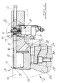
- Fig. 1
- das Schema eines erfindungsgemäßen Blaskopfes im Querschnitt,
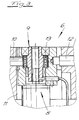
- Fig. 2
- in gegenüber der Fig. 1 wesentlich vergrößertem Maßstab den Ausschnitt A aus dem Gegenstand der Fig. 1,
- Fig. 3
- den nochmals vergrößerten Ausschnitt B aus dem Gegenstand der Fig. 2 und
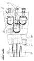
- Fig. 4
- eine Draufsicht auf den Gegenstand der Fig. 2.
- Fig. 1
- the schematic of a blow head according to the invention in cross section,
- Fig. 2
- in a significantly enlarged scale compared to FIG. 1, section A from the subject of FIG. 1,
- Fig. 3
- the again enlarged section B from the subject of Fig. 2 and
- Fig. 4
- 2 shows a top view of the object of FIG. 2.
Die in den Figuren dargestellte Vorrichtung dient zur Herstellung einer Kunststoffolie aus thermoplastischem Kunststoff im sogenannten Folienblasverfahren. In der Fig. 1 ist eine solche Folienblase 1 angedeutet. Die Herstellung der Kunststoffolie erfolgt mit Dickenfehlerkorrektur im laufenden Betrieb. Dazu sind besondere Maßnahmen erforderlich, die weiter unten erläutert werden. In baulicher Gestaltung besteht die Vorrichtung in ihrem grundsätzlichen Aufbau aus einem Blaskopf 2, der eine Ringspaltdüse 3 aufweist, wobei außerdem eine Einrichtung 4 zum Aufblasen der Folienblase verwirklicht ist. Auch insoweit wird auf die Fig. 1 verwiesen.The device shown in the figures is used to produce a plastic film made of thermoplastic in the so-called film blowing process. Such a film bubble 1 is indicated in FIG. 1. The plastic film is manufactured with the correction of the thickness error during operation. This requires special measures, which are explained below. In terms of its construction, the basic structure of the device consists of a
Insbesondere aus der Fig. 2 entnimmt man deutlich, daß die Ringspaltdüse 3 eine äußere Düsenaustrittslippe 5 aus Stahl aufweist. Die Düsenaustrittslippe 5 ist als ein im wesentlichen zylindrisches Bauteil von zumindest einigen Zentimetern Länge und zumindest einigen Millimetern Dicke ausgeführt. Im Ausführungsbeispiel und nach bevorzugter Ausführungsform der Erfindung liegt die Dicke der Düsenaustrittslippe 5 im Bereich zwischen 3 und 5 mm. Ihre Erstreckung in axialer Richtung liegt im Bereich zwischen 3 und 6 cm. Um den Umfang der Düsenaustrittslippe 5 sind äquidistant verteilt in radialer Richtung wirkende Hochkraftstellelemente 6 angeordnet. Insoweit wird auf eine vergleichende Betrachtung der Fig. 2 und 4 verwiesen. Die Anordnung ist so getroffen, daß die Ausgangsspaltdicke des Ringspaltdüsenspaltes S durch eine Vorspannung der Düsenaustrittslippe 5 eingestellt ist, die von den Hochkraftstellelementen 6 erzeugt ist. Im Ausführungsbeispiel wirken diese in radialer Richtung nach innen, so daß die Vorspannung eine Druckvorspannung ist. Die Hochkraftstellelemente 6 gehören einer Regeleinrichtung für die Dickenfehlerkorrektur an. Über die Hochkraftstellelemente 6 ist zum Zwecke der Dickenfehlerkorrektur die Vorspannung der Düsenaustrittslippe 5 veränderbar, und zwar nach Maßgabe von Dickenfehlermessungen an der Kunststoffolie oder nach Maßgabe von Konturmessungen an einem aus der Kunststoffolie gewickelten Coil und über den Umfang der Düsenaustrittslippe 5 auch unterschiedlich.From FIG. 2 in particular it can clearly be seen that the annular gap nozzle 3 has an outer
Im Ausführungsbeispiel sind die Hochkraftstellelemente 6 im Bereich des oberen Randes der Düsenaustrittslippe 5 angeordnet. Das bewirkt, daß im Ausführungsbeispiel lediglich der Bereich des oberen Randes der Düsenaustrittslippe 5 unter Vorspannung gesetzt ist. Die Regeleinrichtung ist als Dickenregeleinrichtung ausgebildet, mit der beim Aufwickeln der Blasfolie in doppelter Lage nach Flachlegen oder in einfacher Lage nach Auftrennen eine von störenden Faßreifen freie Coiloberfläche des beim Aufwickeln sich bildenden Coils einregelbar ist.In the exemplary embodiment, the high-
Aus einer vergleichenden Betrachtung der Fig. 2 und 3 entnimmt man, daß die Hochkraftstellelemente 6 einen umdrehungswinkelsteuerbaren Stellmotor 7 aufweisen, der mit einem Untersetzungsgetriebe 8 ausgerüstet ist. Das Untersetzungsgetriebe 8 arbeitet über einen Treiber 9 und eine Stellstange 10 auf die Düsenaustrittslippe 5. Das Aggregat aus Stellmotor 7, Untersetzungsgetriebe 8 und Treiber 9 ist als einheitliches Bauteil ausgeführt. Es ist im Bereich der Stellstange 10 in eine Bauteilaufnahme 11 eingesetzt und in dieser durch zumindest eine Justierschraube 12 justierbar. Der Stellmotor 7 mag als Schrittmotor ausgeführt sein. Der Treiber 9 ist im Ausführungsbeispiel als Exzentertrieb ausgebildet. Der Exzentertrieb weist eine Exzenterscheibe auf, auf die ein Wälzlager 13 aufgesetzt ist. Dadurch werden Reibungskräfte zwischen dem Treiber 9 und der Stellstange 10 vermieden. Die Düsenaustrittslippe 5 funktioniert zugleich als Rückstellfeder.From a comparative view of FIGS. 2 and 3 it can be seen that the high-
Betrachtet man die Fig. 2 und 4, so erkennt man, daß der Blaskopf 2 eine äußere Düsenaustrittslippe 5 aufweist, die gleichsam den Blaskopfkern 14 umgibt. Diese Düsenaustrittslippe 5 ist von einem Ringraum 15 von einigen Zentimetern Tiefe und Breite umgeben. Der Ringraum 15 ist seinerseits von einem Blaskopfkranz 16 umgeben, der, mit reduziertem Wärmeübergang an einen Bodenbereich des Ringraumes 15 angeschlossen ist. In dem Blaskopfkranz 16 ist das Aggregat aus Stellmotor 7, Untersetzungsgetriebe 8 und Treiber 9 angeordnet. In der Fig. 2 erkennt man, daß die Stellstangen 10 den Ringraum 15 überbrücken. Sie sind in der Wand, die den Ringraum 15 begrenzt, geführt. Der reduzierte Wärmeübergang ist durch einen Kranz von Bohrungen 17 und zwischen den Bohrungen 17 angeordneten dünnen Stegen 18 verwirklicht. Die Fig. 4 macht deutlich, daß die Aggregate aus Stellmotor 7, Untersetzungsgetriebe 8 und Treiber 9 auf zwei Kreisen und von Kreis zu Kreis auf Lücke um den Umfang des Blaskopfes 2 verteilt angeordnet sind. Die Stellstangen 10 verlaufen radial zur Düsenaustrittslippe 5 hin. Auf diese Weise können die Stellstangen 10 gleichsam dicht an dicht an der Düsenaustrittslippe 5 zur Erzeugung und Veränderung der Vorspannung angreifen.2 and 4, it can be seen that the
Im Ausführungsbeispiel und nach bevorzugter Ausführungsform der Erfindung bilden die Düsenaustrittslippe 5 und der Blaskopfkranz 16 ein einheitliches Bauteil, in dem der Ringraum 15 angeordnet ist. Das einheitliche Bauteil weist einen Kragen 19 auf, mit dem es unter Zwischenschaltung eines Zentrierspaltes 20 mit Zentrierschrauben 21 auf ein Blaskopfunterteil 22 aufgesetzt ist.In the exemplary embodiment and according to a preferred embodiment of the invention, the
Claims (13)
- An apparatus for producing a film of synthetic material from synthetic thermoplastic material by the film-blowing process with thickness error correction in continuous operation, having a blowing head (2) which comprises an annular gap extrusion die (3), and having a device (4) for inflating the blown film (1),
wherein the annular gap extrusion die (3) has an outer and/or inner die outlet lip (5) made of steel, which die outlet lip (5) is constructed as a substantially cylindrical component of length at least a few centimetres and is elastically deformable,
wherein adjusting elements acting radially are disposed equidistantly distributed around the periphery of the die outlet lip (5),
wherein the initial gap thickness of the annular gap extrusion die gap (S) is adjusted by a prestressing of the die outlet lip (5) which is produced by the adjusting elements, and
wherein the adjusting elements form part of a regulating device for the correction of thickness errors, and wherein the prestressing of the die outlet lip (5) can be varied by way of the adjusting elements for the purpose of correcting thickness errors, characterised in that the die outlet lip (5) has a thickness of at least a few millimetres, that the adjusting elements are constructed as high-force adjusting elements (6) which comprise a servomotor (7) having a controllable angle of rotation which is equipped with a step-down transmission (8), and that the step-down transmission (8) acts on the die outlet lip (5) via a driver (9) constructed as an eccentric drive and an adjusting rod (10). - An apparatus according to claim 1, wherein the high-force adjusting elements (6) are disposed in the region of the upper edge of the die outlet lip (5) and only the region of the upper edge of the die outlet lip (5) is placed under prestress.
- An apparatus according to either one of claims 1 or 2, wherein the regulating device is constructed as a thickness profile regulating device by means of which a coil surface free from troublesome barrel hoops can be achieved when winding up the blown film.
- An apparatus according to any one of claims 1 to 3, wherein the unit comprising the servomotor (7), the step-down transmission (8) and the driver (9) is designed as a unified unit and can be inserted in a component receiver (11) in the region of the adjusting rod (10) and can be adjusted in the said receiver by at least one adjusting screw (12).
- An apparatus according to either one of claims 3 or 4, wherein the servomotor (7) is designed as a stepper motor.
- An apparatus according to claim 1, wherein the eccentric drive has an eccentric disc on which a rolling bearing (13) is mounted.
- An apparatus according to any one of claims 1 to 6, wherein the die outlet lip (5) is used at the same time as a readjusting spring.
- An apparatus according to any one of claims 1 to 7, wherein the blowing head (2) has an outer die outlet lip (5) which is surrounded by an annular gap (15) of a few centimetres depth and width, wherein the annular gap (15) is itself surrounded by a blowing head ring (16) which is attached to a base region of the annular gap (15) with reduced heat transfer, and wherein the unit comprising the servomotor (7), the step-down transmission (8) and the driver (9) is disposed in the blowing head ring (16).
- An apparatus according to claim 8, wherein the adjusting rods (10) bridge the annular gap (15).
- An apparatus according to either one of claims 8 or 9, wherein the reduced heat transfer is achieved by a ring comprising bores (17) and thin bridges (18) disposed between the bores (17).
- An apparatus according to any one of claims 8 to 10, wherein the units comprising the servomotor (7) the step-down transmission (8) and the driver (9) are disposed on two circles and are disposed from circle to circle distributed on gaps around the periphery of the blowing head (2), and wherein the adjusting rods (10) extend radially towards the die outlet lip (5).
- An apparatus according to any one of claims 8 to 11, wherein the die outlet lip (5) and the blowing head ring (16) form a unified component in which the annular gap (15) and the bores (17) are disposed.
- An apparatus according to any one of claims 8 to 12, wherein the unified component has a collar (19) with which it is placed on a blowing head lower part (22) with a centring gap (20) disposed therebetween and with centring screws (21).
Applications Claiming Priority (2)
| Application Number | Priority Date | Filing Date | Title |
|---|---|---|---|
| DE4106486 | 1991-03-01 | ||
| DE4106486A DE4106486C1 (en) | 1991-03-01 | 1991-03-01 |
Publications (2)
| Publication Number | Publication Date |
|---|---|
| EP0501137A1 EP0501137A1 (en) | 1992-09-02 |
| EP0501137B1 true EP0501137B1 (en) | 1995-09-27 |
Family
ID=6426196
Family Applications (1)
| Application Number | Title | Priority Date | Filing Date |
|---|---|---|---|
| EP92101039A Expired - Lifetime EP0501137B1 (en) | 1991-03-01 | 1992-01-23 | Device for the manufacture of a plastic film |
Country Status (5)
| Country | Link |
|---|---|
| US (1) | US5217721A (en) |
| EP (1) | EP0501137B1 (en) |
| JP (1) | JPH0741661B2 (en) |
| DE (1) | DE4106486C1 (en) |
| ES (1) | ES2077883T3 (en) |
Families Citing this family (10)
| Publication number | Priority date | Publication date | Assignee | Title |
|---|---|---|---|---|
| DE19509069C1 (en) * | 1995-03-14 | 1996-01-18 | Reifenhaeuser Masch | Extruder for thermoplastic plastics for high actuating forces |
| US5674440A (en) * | 1995-05-05 | 1997-10-07 | Graham Engineering Corporation | Die head with adjustable mandrel and method |
| US6461260B1 (en) | 2000-05-15 | 2002-10-08 | Worth, Inc. | Composite wrap bat |
| DE102004028100B4 (en) * | 2004-06-09 | 2009-09-17 | Thermo-Technik-Systeme Gmbh | extrusion die |
| JP6913024B2 (en) * | 2015-11-27 | 2021-08-04 | 住友重機械モダン株式会社 | Film molding equipment |
| CN106079404A (en) * | 2016-06-20 | 2016-11-09 | 安庆市鑫顺塑业有限公司 | A kind of plastic membrane blowing device |
| TWI755398B (en) * | 2017-05-26 | 2022-02-21 | 日商住友重機械摩登股份有限公司 | Film forming device |
| EP4309871A1 (en) * | 2021-03-16 | 2024-01-24 | The Japan Steel Works, Ltd. | Lip spacing adjustment device, extrusion-molding die, extrusion -molding device, lip spacing adjustment method, and film manufacturing method |
| CN115157631A (en) * | 2022-07-02 | 2022-10-11 | 佛山市必创自动化设备有限公司 | Servo wall thickness control driving system |
| CN116811085B (en) * | 2023-06-06 | 2024-02-20 | 广东汇发塑业科技有限公司 | Real-time evaluation method for running state of multilayer coextrusion film blowing machine |
Family Cites Families (19)
| Publication number | Priority date | Publication date | Assignee | Title |
|---|---|---|---|---|
| DE1218702B (en) * | 1963-08-27 | 1966-06-08 | Rheinstahl Henschel Ag | Device for adjusting a damming element in slot nozzles |
| GB1090469A (en) * | 1965-08-10 | 1967-11-08 | Agfa Gevaert Nv | Screw adjustment mechanism |
| AT313554B (en) * | 1966-12-30 | 1974-02-25 | Conduco Ag | Device for adjusting the annular gap of a spray head for the production of pipes and hoses made of thermoplastic material |
| US3975132A (en) * | 1975-06-05 | 1976-08-17 | United Industrial Syndicate, Inc. | Devices for use in the application of working pressures and apparatus including such devices |
| JPS5837139A (en) * | 1981-08-26 | 1983-03-04 | Power Reactor & Nuclear Fuel Dev Corp | Regeneration of cold trap |
| DE3427912C1 (en) * | 1984-07-28 | 1986-03-06 | Reifenhäuser GmbH & Co Maschinenfabrik, 5210 Troisdorf | Extrusion unit for the extrusion of thermoplastic |
| DE3505837C2 (en) * | 1985-02-20 | 1994-06-23 | Battenfeld Extrusionstech | Spray head for the production of pipes made of thermoplastic |
| IT1184790B (en) * | 1985-05-15 | 1987-10-28 | O M I P A Italia Di Cazzani Gi | FLAT EXTRUSION HEAD FOR STRATIFORM PLASTIC MATERIAL |
| JPS625815A (en) * | 1985-07-01 | 1987-01-12 | Ishikawajima Harima Heavy Ind Co Ltd | Thickness control device for parison |
| DE3740087A1 (en) * | 1987-11-26 | 1989-07-20 | Reifenhaeuser Masch | Process for producing a film from thermoplastic material with the aid of a slot die |
| DE3805774A1 (en) * | 1988-02-24 | 1989-09-07 | Sigmund Boos | SLOT NOZZLE, ESPECIALLY WIDE SLOT NOZZLE, FOR EXTRUDING PLANTS IN THE PLASTIC INDUSTRY |
| DE8810470U1 (en) * | 1988-08-18 | 1988-11-03 | A-Z Formen- Und Maschinenbau Gmbh, 8000 Muenchen, De | |
| DE8813801U1 (en) * | 1988-11-04 | 1988-12-22 | Roehm Gmbh, 6100 Darmstadt, De | |
| US5066435A (en) * | 1989-09-16 | 1991-11-19 | Rohm Gmbh Chemische Fabrik | Process and system for producing multi-layer extrudate |
| US4978289A (en) * | 1989-10-05 | 1990-12-18 | Jyohoku Seiko Co., Ltd. | Film extrusion die |
| DE4000530A1 (en) * | 1989-10-26 | 1991-05-02 | Reifenhaeuser Masch | Prodn. of blown thermoplastic film - measuring thickness profile and number of reeled turns and feeding data to computer to balance variations by regulating die accordingly |
| DE4013610A1 (en) * | 1989-10-26 | 1991-05-02 | Reifenhaeuser Masch | Blown film extruder thickness error corrector - comprises elastically deformable annular die lip acted upon by piezoelectric elements |
| DE3936496A1 (en) * | 1989-11-02 | 1991-05-08 | Krauss Maffei Ag | CENTERING DEVICE FOR A TUBE EXTRUSION HEAD |
| DE4013611C2 (en) * | 1990-04-27 | 1994-03-31 | Reifenhaeuser Masch | Process for producing a plastic film and for winding the plastic film into a coil |
-
1991
- 1991-03-01 DE DE4106486A patent/DE4106486C1/de not_active Expired - Fee Related
-
1992
- 1992-01-23 EP EP92101039A patent/EP0501137B1/en not_active Expired - Lifetime
- 1992-01-23 ES ES92101039T patent/ES2077883T3/en not_active Expired - Lifetime
- 1992-02-19 JP JP4031891A patent/JPH0741661B2/en not_active Expired - Lifetime
- 1992-02-25 US US07/841,337 patent/US5217721A/en not_active Expired - Fee Related
Also Published As
| Publication number | Publication date |
|---|---|
| JPH0741661B2 (en) | 1995-05-10 |
| EP0501137A1 (en) | 1992-09-02 |
| ES2077883T3 (en) | 1995-12-01 |
| US5217721A (en) | 1993-06-08 |
| DE4106486C1 (en) | 1992-09-17 |
| JPH04320825A (en) | 1992-11-11 |
Similar Documents
| Publication | Publication Date | Title |
|---|---|---|
| DE3640197C2 (en) | ||
| EP1511598B1 (en) | Machine for superfinishing by honing | |
| EP0501137B1 (en) | Device for the manufacture of a plastic film | |
| EP2753838B1 (en) | Manufacturing method of a rolling bearing | |
| EP2498970B1 (en) | Device and method for producing film tubing | |
| EP0970770A1 (en) | Apparatus and method for working drill holes | |
| DE3039467A1 (en) | HONING MACHINE FOR MACHINING WORK PIECE BORES, ESPECIALLY BAG HOLES AND METHOD FOR OPERATING THE HONING MACHINE | |
| EP0075809A1 (en) | Device for the production of tubes of plastics material | |
| DE1812671A1 (en) | Drilling device | |
| EP2708324A1 (en) | Table top for the spring support table of a spring end grinding machine and spring end grinding machine with the same | |
| DE3125746A1 (en) | DIFFERENTIAL SCREW ACTUATOR | |
| EP3164244A1 (en) | Honing tool and honing method | |
| EP0501147A1 (en) | Extrusion tool for the extrusion of thermoplastic material | |
| EP0602333A1 (en) | Grinding-disc for working of workpiece-surfaces | |
| DE19741520A1 (en) | Alignment apparatus for loading semiconductor wafer with notch onto cassette | |
| WO1992018287A1 (en) | Honing tool for machining bores | |
| DE60210569T2 (en) | Method and device for installing a landing gear on the structure of an aircraft and equipped with such a landing gear aircraft | |
| EP2112260B1 (en) | Circular knitting machine with a rotatable installed dial | |
| EP2072201A1 (en) | Edge scanner | |
| EP0885711B1 (en) | Extrusion head for an apparatus to extrusion blow mould hollow articles, especially plastic fuel tanks | |
| DE60222839T2 (en) | A method of manufacturing a pneumatic tire comprising a cord reinforced layer | |
| EP1016483A2 (en) | Hob and mandrel assembly | |
| DE3522337A1 (en) | ROBOT JOINT WITH AN ELECTRIC DRIVE MOTOR | |
| EP3820646A1 (en) | Honing method and machine tool for contour honing | |
| DE3513411C2 (en) |
Legal Events
| Date | Code | Title | Description |
|---|---|---|---|
| PUAI | Public reference made under article 153(3) epc to a published international application that has entered the european phase |
Free format text: ORIGINAL CODE: 0009012 |
|
| AK | Designated contracting states |
Kind code of ref document: A1 Designated state(s): ES FR GB IT |
|
| 17P | Request for examination filed |
Effective date: 19920725 |
|
| 17Q | First examination report despatched |
Effective date: 19940324 |
|
| GRAA | (expected) grant |
Free format text: ORIGINAL CODE: 0009210 |
|
| AK | Designated contracting states |
Kind code of ref document: B1 Designated state(s): ES FR GB IT |
|
| ITF | It: translation for a ep patent filed |
Owner name: ING. A. GIAMBROCONO & C. S.R.L. |
|
| REG | Reference to a national code |
Ref country code: ES Ref legal event code: FG2A Ref document number: 2077883 Country of ref document: ES Kind code of ref document: T3 |
|
| GBT | Gb: translation of ep patent filed (gb section 77(6)(a)/1977) |
Effective date: 19951110 |
|
| PGFP | Annual fee paid to national office [announced via postgrant information from national office to epo] |
Ref country code: GB Payment date: 19951221 Year of fee payment: 5 |
|
| PGFP | Annual fee paid to national office [announced via postgrant information from national office to epo] |
Ref country code: FR Payment date: 19960116 Year of fee payment: 5 |
|
| PGFP | Annual fee paid to national office [announced via postgrant information from national office to epo] |
Ref country code: ES Payment date: 19960124 Year of fee payment: 5 |
|
| ET | Fr: translation filed | ||
| PLBE | No opposition filed within time limit |
Free format text: ORIGINAL CODE: 0009261 |
|
| STAA | Information on the status of an ep patent application or granted ep patent |
Free format text: STATUS: NO OPPOSITION FILED WITHIN TIME LIMIT |
|
| 26N | No opposition filed | ||
| PG25 | Lapsed in a contracting state [announced via postgrant information from national office to epo] |
Ref country code: GB Effective date: 19970123 |
|
| PG25 | Lapsed in a contracting state [announced via postgrant information from national office to epo] |
Ref country code: ES Free format text: LAPSE BECAUSE OF NON-PAYMENT OF DUE FEES Effective date: 19970124 |
|
| GBPC | Gb: european patent ceased through non-payment of renewal fee |
Effective date: 19970123 |
|
| PG25 | Lapsed in a contracting state [announced via postgrant information from national office to epo] |
Ref country code: FR Effective date: 19970930 |
|
| REG | Reference to a national code |
Ref country code: FR Ref legal event code: ST |
|
| REG | Reference to a national code |
Ref country code: ES Ref legal event code: FD2A Effective date: 19990503 |
|
| PG25 | Lapsed in a contracting state [announced via postgrant information from national office to epo] |
Ref country code: IT Free format text: LAPSE BECAUSE OF NON-PAYMENT OF DUE FEES;WARNING: LAPSES OF ITALIAN PATENTS WITH EFFECTIVE DATE BEFORE 2007 MAY HAVE OCCURRED AT ANY TIME BEFORE 2007. THE CORRECT EFFECTIVE DATE MAY BE DIFFERENT FROM THE ONE RECORDED. Effective date: 20050123 |