EP0500961B1 - Systeme de codage de la parole - Google Patents
Systeme de codage de la parole Download PDFInfo
- Publication number
- EP0500961B1 EP0500961B1 EP91915981A EP91915981A EP0500961B1 EP 0500961 B1 EP0500961 B1 EP 0500961B1 EP 91915981 A EP91915981 A EP 91915981A EP 91915981 A EP91915981 A EP 91915981A EP 0500961 B1 EP0500961 B1 EP 0500961B1
- Authority
- EP
- European Patent Office
- Prior art keywords
- vectors
- vector
- computation
- delta
- code
- Prior art date
- Legal status (The legal status is an assumption and is not a legal conclusion. Google has not performed a legal analysis and makes no representation as to the accuracy of the status listed.)
- Expired - Lifetime
Links
- 239000013598 vector Substances 0.000 claims description 533
- 238000012545 processing Methods 0.000 claims description 79
- 238000004458 analytical method Methods 0.000 claims description 67
- 238000011156 evaluation Methods 0.000 claims description 40
- 125000004122 cyclic group Chemical group 0.000 claims description 17
- 238000010606 normalization Methods 0.000 claims description 2
- 238000005457 optimization Methods 0.000 description 38
- 238000009825 accumulation Methods 0.000 description 27
- 230000009466 transformation Effects 0.000 description 23
- 238000010586 diagram Methods 0.000 description 17
- 239000011159 matrix material Substances 0.000 description 17
- 238000013139 quantization Methods 0.000 description 16
- 230000003321 amplification Effects 0.000 description 11
- 238000003199 nucleic acid amplification method Methods 0.000 description 11
- 238000010276 construction Methods 0.000 description 10
- 238000009826 distribution Methods 0.000 description 10
- 230000008707 rearrangement Effects 0.000 description 10
- 238000007792 addition Methods 0.000 description 7
- 230000003044 adaptive effect Effects 0.000 description 6
- 238000000034 method Methods 0.000 description 6
- 230000005540 biological transmission Effects 0.000 description 4
- 238000004364 calculation method Methods 0.000 description 4
- 230000008901 benefit Effects 0.000 description 3
- 230000007246 mechanism Effects 0.000 description 3
- 230000004044 response Effects 0.000 description 3
- HIIJOGIBQXHFKE-HHKYUTTNSA-N Ala-Thr-Ala-Pro Chemical compound C[C@H](N)C(=O)N[C@@H]([C@H](O)C)C(=O)N[C@@H](C)C(=O)N1CCC[C@H]1C(O)=O HIIJOGIBQXHFKE-HHKYUTTNSA-N 0.000 description 2
- 230000006978 adaptation Effects 0.000 description 2
- 230000001413 cellular effect Effects 0.000 description 2
- 230000006835 compression Effects 0.000 description 2
- 238000007906 compression Methods 0.000 description 2
- 239000000470 constituent Substances 0.000 description 2
- 230000004069 differentiation Effects 0.000 description 2
- 230000000694 effects Effects 0.000 description 2
- 230000006872 improvement Effects 0.000 description 2
- 230000004048 modification Effects 0.000 description 2
- 238000012986 modification Methods 0.000 description 2
- 238000003786 synthesis reaction Methods 0.000 description 2
- 210000001260 vocal cord Anatomy 0.000 description 2
- 230000015572 biosynthetic process Effects 0.000 description 1
- 230000008859 change Effects 0.000 description 1
- 238000004891 communication Methods 0.000 description 1
- 238000007796 conventional method Methods 0.000 description 1
- 238000010219 correlation analysis Methods 0.000 description 1
- 230000003111 delayed effect Effects 0.000 description 1
- 230000006866 deterioration Effects 0.000 description 1
- 230000006870 function Effects 0.000 description 1
- 230000003287 optical effect Effects 0.000 description 1
- 230000009467 reduction Effects 0.000 description 1
- 230000001131 transforming effect Effects 0.000 description 1
Images


Classifications
-
- G—PHYSICS
- G10—MUSICAL INSTRUMENTS; ACOUSTICS
- G10L—SPEECH ANALYSIS OR SYNTHESIS; SPEECH RECOGNITION; SPEECH OR VOICE PROCESSING; SPEECH OR AUDIO CODING OR DECODING
- G10L19/00—Speech or audio signals analysis-synthesis techniques for redundancy reduction, e.g. in vocoders; Coding or decoding of speech or audio signals, using source filter models or psychoacoustic analysis
- G10L19/04—Speech or audio signals analysis-synthesis techniques for redundancy reduction, e.g. in vocoders; Coding or decoding of speech or audio signals, using source filter models or psychoacoustic analysis using predictive techniques
- G10L19/08—Determination or coding of the excitation function; Determination or coding of the long-term prediction parameters
- G10L19/12—Determination or coding of the excitation function; Determination or coding of the long-term prediction parameters the excitation function being a code excitation, e.g. in code excited linear prediction [CELP] vocoders
-
- G—PHYSICS
- G10—MUSICAL INSTRUMENTS; ACOUSTICS
- G10L—SPEECH ANALYSIS OR SYNTHESIS; SPEECH RECOGNITION; SPEECH OR VOICE PROCESSING; SPEECH OR AUDIO CODING OR DECODING
- G10L19/00—Speech or audio signals analysis-synthesis techniques for redundancy reduction, e.g. in vocoders; Coding or decoding of speech or audio signals, using source filter models or psychoacoustic analysis
- G10L2019/0001—Codebooks
- G10L2019/0002—Codebook adaptations
-
- G—PHYSICS
- G10—MUSICAL INSTRUMENTS; ACOUSTICS
- G10L—SPEECH ANALYSIS OR SYNTHESIS; SPEECH RECOGNITION; SPEECH OR VOICE PROCESSING; SPEECH OR AUDIO CODING OR DECODING
- G10L19/00—Speech or audio signals analysis-synthesis techniques for redundancy reduction, e.g. in vocoders; Coding or decoding of speech or audio signals, using source filter models or psychoacoustic analysis
- G10L2019/0001—Codebooks
- G10L2019/0007—Codebook element generation
-
- G—PHYSICS
- G10—MUSICAL INSTRUMENTS; ACOUSTICS
- G10L—SPEECH ANALYSIS OR SYNTHESIS; SPEECH RECOGNITION; SPEECH OR VOICE PROCESSING; SPEECH OR AUDIO CODING OR DECODING
- G10L19/00—Speech or audio signals analysis-synthesis techniques for redundancy reduction, e.g. in vocoders; Coding or decoding of speech or audio signals, using source filter models or psychoacoustic analysis
- G10L2019/0001—Codebooks
- G10L2019/0013—Codebook search algorithms
- G10L2019/0014—Selection criteria for distances
-
- G—PHYSICS
- G10—MUSICAL INSTRUMENTS; ACOUSTICS
- G10L—SPEECH ANALYSIS OR SYNTHESIS; SPEECH RECOGNITION; SPEECH OR VOICE PROCESSING; SPEECH OR AUDIO CODING OR DECODING
- G10L25/00—Speech or voice analysis techniques not restricted to a single one of groups G10L15/00 - G10L21/00
- G10L25/03—Speech or voice analysis techniques not restricted to a single one of groups G10L15/00 - G10L21/00 characterised by the type of extracted parameters
- G10L25/06—Speech or voice analysis techniques not restricted to a single one of groups G10L15/00 - G10L21/00 characterised by the type of extracted parameters the extracted parameters being correlation coefficients
Definitions
- the present invention relates to a speech coding system for compression of data of speech signals, more particularly relates to a speech coding system using analysis-by-synthesis (A-b-S) type vector quantization for coding at a transmission speed of 4 to 16 kbps, that is, using vector quantization performing analysis by synthesis.
- A-b-S analysis-by-synthesis
- Speech coders using A-b-S type vector quantization for example, code-excited linear prediction (CELP) coders
- CELP code-excited linear prediction
- coders predictive weighting is applied to the code vectors of a codebook to produce reproduced signals, the error powers between the reproduced signals and the input speech signal are evaluated, and the number (index) of the code vector giving the smallest error is decided on and sent to the receiver side.
- a coder using the above-mentioned A-b-S type vector quantization system performs processing so as to apply linear preduction analysis filter processing to each of the vectors of the sound generator signals, of which there are about 1000 patterns, stored in the codebook, and retrieve from among the approximately 1000 patterns the one giving the smallest error between the reproduced speech signals and the input speech signal to be coded.
- the above-mentioned retrieval processing must be performed in real time. This being so, the retrieval processing must be performed continuously during the conversation at short time intervals of 5 ms, for example.
- the retrieval processing includes complicated computation operations of filter computation and correlation computation.
- the amount of computation required for these computation operations is huge, being, for example, several 100M multiplications and additions per second.
- DSP digital signal processors
- the present invention in consideration of the above-mentioned problems, has as its object the provision of a speech coding system which can tremendously reduce the amount of computation while maintaining as is the properties of an A-b-S type vector quantization coder of high quality and high efficiency.
- the present invention adds differential vectors (hereinafter referred to as delta vectors) ⁇ C n to the previous code vectors C n-1 among the code vectors of the codebook and stores in the codebook the group of code vectors producing the next code vectors C n .
- delta vectors differential vectors
- Figure 1 is a view for explaining the mechanism of speech generation.
- Speech includes voiced sounds and unvoiced sounds.
- Voiced sounds are produced based on the generation of pulse sounds through vibration of the vocal cords and are modified by the speech path characteristics of the throat and mouth of the individual to form part of the speech.
- the unvoiced sounds are sounds produced without vibration of the vocal cords and pass through the speech path to become part of the speech using a simple Gaussian noise train as the source of the sound. Therefore, the mechanism for generation of speech, as shown in Fig. 1, can be modeled as a pulse sound generator PSG serving as the origin for voiced sounds, a noise sound generator NSG serving as the origin for unvoiced sounds, and a linear preduction analysis filter LPCF for adding speech path characteristics to the signals output from the sound generators (PSG and NSG).
- PSG pulse sound generator
- NSG serving as the origin for unvoiced sounds
- LPCF linear preduction analysis filter
- an adaptive codebook is used to identify the pulse period of the pulse sound generator based on the periodicity of the input speech signal, the pulse train having the period is input to the linear prediction analysis filter, filter computation processing is performed, the resultant filter computation results are subtracted from the input speech signal, and the period component is removed.
- a predetermined number of noise trains (each noise train being expressed by a predetermined code vector of N dimensions) are prepared. If the single code vector giving the smallest error between the reproduced signal vectors composed of the code vectors subjected to analysis filter processing and the input signal vector (N dimension vector) from which the period component has been removed can be found, then it is possible to code the speech by a code (data) specifying the period and the code vector. The data is sent to the receiver side where the original speech (input speech signal) is reproduced. This data is highly compressed information.
- Figure 2 is a block diagram showing the general construction of an A-b-S type vector quantization speech coder.
- reference numeral 1 indicates a noise codebook which stores a number, for example, 1024 types, of noise trains C (each noise train being expressed by an N dimension code vector) generated at random
- 2 indicates an amplifying unit with a gain g
- 3 indicates a linear prediction analysis filter which performs analysis filter computation processing simulating speech path characteristics on the output of the amplifying unit
- 4 indicates an error generator which outputs errors between reproduced signal vectors output from the linear prediction analysis filter 3 and the input signal vector
- 5 indicates an error power evaluation unit which evaluates the errors and finds the noise train (code vector) giving the smallest error.
- the optimial gain g is multiplied with the code vectors (C) of the noise codebook 1, then filter processing is performed by the linear prediction analysis filter 3, the error signals (E) between the reproduced signal vectors (gAC) obtained by the filter processing and the input speech signal vector (AX) are found by the error generator 4, retrieval is performed on the noise codebook 1 using the power of the error signals as the evaluation function (distance scale) by the error power evaluation unit 5, the noise train (code vector) giving the smallest error power is found, and the input speech signal is coded by a code specifying the said noise train (code vector).
- A is a perceptual weighting matrix.
- E 2 AX-gAC 2
- the optimal code vector C and the gain g are determined by making the error power shown in equation (1) the smallest possible. Note that the power differs depending on the loudness of the voice, so the gain g is optimized and the power of the reproduced signal gAC is matched with the power of the input speech signal AX.
- the optimal gain may be found by partially differentiating equation (1) by g and making it 0.
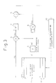
- Figure 3 is a block diagram showing in more detail the portion of the codebook retrieval processing in the construction of Fig. 2. That is, it is a view of the portion of the noise codebook retrieval processing for coding the input signal by finding the noise train (code vector) giving the smallest error power.
- Reference numeral 1 indicates a noise codebook which stores M types (size M) of noise trains C (each noise train being expressed by an N dimensional code vector), and 3 a linear prediction analysis filter (LPC filter) of Np analysis orders which applies filter computation processing simulating speech path characteristics. Note that an explanation of the amplifying unit 2 of Fig. 2 is omitted.
- 7 is a square computation unit which computes the square of the cross correlation R XC
- 9 is a division unit which computes R XC 2 /R CC
- 10 is an error power evaluation and determination unit which determines the noise train (code vector) giving the largest R XC 2 /R CC , in other words, the smallest error power, and thereby specifies the code vector.
- K 10 3 .
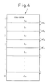
- Figure 4 is a view showing the basic thinking of the present invention.
- the noise codebook 1 of the figure stores M number of noise trains, each of N dimensions, as the code vectors C 0 , C 1 , C 2 ... C 3 , C 4 ... C m .
- the code vectors C 0 , C 1 , C 2 ... C 3 , C 4 ... C m There is no relationship among these code vectors. Therefore, in the past, to perform the retrieval processing of Fig. 3, the computation for evaluation of the error power was performed completely independently for each and every one of the m number of code vectors.
- the code vector C 2 for example, in the above-mentioned equations, it includes as an element the code vector C 1 . This being so, when computation is performed on the code vector C 2 , the portion relating to the code vector C 1 has already been completed and if use is made of the results, it is sufficient to change only the delta vector ⁇ C 2 for the remaining computation.
- the delta vectors ⁇ C be made as simple as possible. If the delta vectors ⁇ C are complicated, then in the case of the above example, there would not be that much of a difference between the amount of computation required for independent computation of the code vector C 2 as in the past and the amount of computation for changing the delta vector ⁇ C 2 .
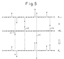
- Figure 5 is a view showing simply the concept of the first embodiment based on the present invention.
- Any next code vector for example, the i-th code vector C i , becomes the sum of the previous code vector, that is, the code vector C i-1 , and the delta vector ⁇ C i .
- the delta vector ⁇ C i has to be as simple as possible as mentioned above.
- the rows of black dots drawn along the horizontal axes of the sections C i-1 , ⁇ C i , and C i in Fig. 5 are N in number (N samples) in the case of an N dimensional code vector and correspond to sample points on the waveform of a noise train.
- the delta vector ⁇ C i is comprised of just four significant sampled data ⁇ 1, ⁇ 2, ⁇ 3, and ⁇ 4, which is extremely simple.
- code vectors C i-1 and C i of Fig. 5 the example was shown of the use of the sparsed code vectors, that is, code vectors previously processed so as to include a large number of codes of a sample value of zero.
- the sparsing technique of code vectors is known.
- delta vector groups are successively stored in a delta vector codebook 11 (mentioned later) so that the difference between any two adjoining code vectors C i-1 and C i becomes the simple delta vector ⁇ C i .
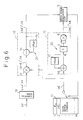
- Figure 6 is a block diagram showing in more detail the portion of the codebook retrieval processing based on the first embodiment. Basically, this corresponds to the construction in the previously mentioned Fig. 3, but Fig. 6 shows an example of the application to a speech coder of the known sequential optimization CELP type. Therefore, instead of the input speech signalAX (Fig. 3), the perceptually weighted pitch prediction error signal vector AY is shown, but this has no effect on the explanation of the invention. Further, the computing means 19 is shown, but this is a previous processing stage accompanying the shift of the linear prediction analysis filter 3 from the position shown in Fig. 3 to the position shown in Fig. 6 and is not an important element in understanding the present invention.
- the element corresponding to the portion for generating the cross correlation R XC in Fig. 3 is the cross correlation computation unit 12 of Fig. 6.
- the element corresponding to the portion for generating the auto correlation R CC of Fig. 3 is the auto correlation computation unit 13 of Fig. 6.
- the cyclic adding means 20 for realizing the present invention is shown as the adding unit 14 and the delay unit 15.
- the cyclic adding means 20 for realizing the present invention is shown as the adding unit 16 and the delay unit 17.
- the code vectors C 0 , C 1 , C 2 ... are not stored as in the noise codebook 1 of Fig. 3. Rather, after the initial vector C 0 , the delta vectors ⁇ C 1 , ⁇ C 2 , ⁇ C 3 ..., the differences from the immediately preceding vectors, are stored.
- the perceptually weighted pitch prediction error signal vector A Y is transformed to A T A Y by the computing means 21, the delta vectors ⁇ C of the delta vector codebook 11 are given to the cross correlation computation unit 12 as they are for multiplication, and the previous correlation value (A C i-1 ) T A Y is cyclically added, so as to produce the correlation (A C ) T A Y of the two.
- the delta vectors ⁇ C are cyclically added with the previous code vectors C i-1 , so as to produce the code vectors C i , and the auto correlation values (A C ) T A C of the code vectors A C after perceptually weighted reproduction are found and given to the evaluation unit 5.
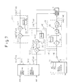
- Figure 7 is a block diagram showing in more detail the portion of the codebook retrieval processing based on the first embodiment using another example. It shows the case of application to a known simultaneous optimization CELP type speech coder.
- the first and second computing means 19-1 and 19-2 are not directly related to the present invention.
- the cross correlation computation unit (12) performs processing in parallel divided into the input speech system and the pitch P (previously mentioned period) system, so is made the first and second cross correlation computation units 12-1 and 12-2.
- the input speech signal vector A X is transformed into A T A X by the first computing means 19-1 and the pitch prediction differential vector A P is transformed into A T A P by the second computing means 19-2.
- the delta vectors ⁇ C are multiplied by the first and second cross correlation computation units 12-1 and 12-2 and are cyclically added to produce the (A C ) T A X and (A C ) T A P .
- the auto correlation computation unit 13 similarly produces (A C ) T A C and gives the same to the evaluation unit 5, so the amount of computation for just the delta vectors is sufficient.
- Figure 8 is a view showing another example of the auto correlation computation unit.
- the auto correlation computation unit 13 shown in Fig. 6 and Fig. 7 can be realized by another construction as well.
- the computer 21 shown here is designed so as to deal with the multiplication required in the analysis filter 3 and the auto correlation computation unit 8 in Fig. 6 and Fig. 7 by a single multiplication operation.
- the previous code vectors C i-1 and the perceptually weighted matrix A correlation values A T A are stored.
- the computation with the delta vectors ⁇ C i is performed and cyclic addition is performed by the adding unit 16 and the delay unit 17 (cyclic adding means 20), whereby it is possible to find the auto correlation values (A C ) T A C .
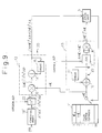
- Figure 9 is a block diagram showing in more detail the portion of the codebook retrieval processing under the first embodiment using another example. Basically, this corresponds to the structure of the previously explained Fig. 3, but Fig. 9 shows an example of application to a pitch orthogonal transformation optimization CELP type speech coder.
- the block 22 positioned after the computing means 19' is a time-reversing orthogonal transformation unit.
- the time-reversing perceptually weighted input speech signal vectors A T A X are calculated from the perceptually weighted input speech signal vectors A X by the computation unit 19', then the time-reversing perceptually weighted orthogonally transformed input speech signal vectors (AH) T A X are calculated with respect to the optimal perceptually weighted pitch prediction differential vector A P by the time-reversing orthogonal transformation unit 22.
- the computation unit 19' and the time-reversing orthogonal transformation unit 22 are not directly related to the gist of the present invention.
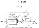
- FIG. 10 is a view showing another example of the auto correlation computation unit.
- the auto correlation computation unit 13 shown in Fig. 9 can be realized by another construction as well. This corresponds to the construction of the above-mentioned Fig. 8.
- the computer 23 shown here can perform the multiplication operations required in the analysis filter (AH)3' and the auto correlation computation unit 8 in Fig. 9 by a single multiplication operation.
- H is changed in accordance with the optimal A P .
- the above-mentioned first embodiment gave the code vectors C 1 , C 2 , C 3 ... stored in the conventional noise codebook 1 in a virtual manner by linear accumulation of the delta vectors ⁇ C 1 , ⁇ C 2 , ⁇ C 3 ...
- the delta vectors are made sparser by taking any four samples in the for example 40 samples as significant data (sample data where the sample value is not zero). Except for this, however, no particular regularity is given in the setting of the delta vectors.
- the second embodiment explained next produces the delta vector groups with a special regularity so as to try to vastly reduce the amount of computation required for the codebook retrieval processing. Further, the second embodiment has the advantage of being able to tremendously slash the size of the memory in the delta vector codebook 11. Below the second embodiment will be explained in more detail.
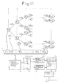
- Figure 11 is a view showing the basic construction of the second embodiment based on the present invention.
- the concept of the second embodiment is shown illustratively at the top half of Fig. 11.
- the delta vectors for producing the virtually formed, for example, 1024 patterns of code vectors are arranged in a tree-structure with a certain regularity with a + or - polarity. By this, it is possible to resolve the filter computation and the correlation computation with computation on just (L-1) number (where L is for example 10) delta vectors and it is possible to tremendously reduce the amount of computation.
- a predetermined single reference noise train, the initial vector C 0 , and (L-1) types of delta noise trains, the delta vectors ⁇ C 1 to ⁇ C L-1 (L 10), are stored in the delta vector codebook 11, the delta vectors ⁇ C 1 to ⁇ C L-1 are added (+) and subtracted (-) with the initial vector C 0 for each layer, to express the (2 10 -1) types of noise train code vectcrs C 0 to C 1022 successively in a tree-structure. Further, a zero vector or - C 0 vector is added to these code vectors to express 2 10 patterns of code vectors C 0 to C 1023 .
- the filter outputs A C 3 to A C 6 for the two types of noise train code vectors C 3 and C 4 and the code vectors C 5 and C 6 are computed.
- the filter output A ⁇ C i-1 of the (i-1)th delta vector is made to act and the filter output A ⁇ C i of the i-th delta vector is made to act on the computed filter output A C k and the filter outputs A C 2k-1 and A C 2k+2 for the two noise train code vectors are computed, thereby generating the filter outputs of all the code vectors.
- the noise train (code vector) giving the smallest error power is determined by the error power evaluation and determination unit 10 and the code specifiying the code vector is output by the speech coding unit 30 for speech coding.
- the auto correlation computation unit 13 is designed to compute the present cross correlations R CC (2k+1) and R CC (2k+2) using the R CC (k) of one layer earlier. If this is done, then it is possible to compute the auto correlations R CC using the total L number of auto correlations (A C 0 ) 2 and (A ⁇ C 1 ) 2 to (A ⁇ C L-1 ) 2 of the filter output A C 0 of the initial vector and the filter outputs A ⁇ C 1 to A ⁇ C L-1 of the (L-1) types of delta vectors and the (L 2 -1)/2 cross correlations with the filter outputs A C 0 and A ⁇ C 1 to A ⁇ C L-1 .
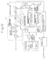
- Figure 12 is a view showing in more detail the second embodiment of Fig. 11.
- Reference numeral 3 is the previously mentioned linear prediction analysis filter (LPC filter) which performs filter computation processing simulating the speech path characteristics.
- LPC filter linear prediction analysis filter
- N P order IIR (infinite impulse response) type filter It is comprised of an N P order IIR (infinite impulse response) type filter.
- An N X N square matrix A and code vector C matrix computation is performed to perform analysis filter processing on the code vector C.
- the N P number of coefficients of the IIR type filter differs based on the input speech signal AX and is determined by a known method with each occurrence. That is, there is correlation between adjoining samples of input speech signals, so the coefficient of correlation between the samples is found, the partial auto correlation coefficient, known as the Parcor coefficient, is found from the said coefficient of correlation, the ⁇ coefficient of the IIR filter is determined from the Parcor coefficient, the N X N square matrix A is prepared using the impulse response train of the filter, and analysis filter processing is performed on the code vector.
- IIR infinite impulse response
- Reference numeral 10 is the error power evaluation and determination unit which determines the noise train (code vector) giving the largest R XC 2 /R CC , in other words, the smallest error power
- 30 is a speech coding unit which codes the input speech signals by a code specifying the noise train (code vector) giving the smallest error power.
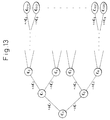
- Figure 13 is a view for explaining the tree-structure array of delta vectors characterizing the second embodiment.
- the delta vectors ⁇ C 1 to ⁇ C L-1 are added (+) or subtracted (-) at each layer with respect to the initial vector C 0 so as to virtually express (2 10 -1) types of code vectors C 0 to C 1022 successively in a tree-structure.
- Zero vectors (all sample values of N dimensional samples being zero) are added to these code vectors to express 2 10 code vectors C 0 to C 1023 .
- i 1, 2, L-1, 2 i-1 ⁇ k ⁇ 2 i -1
- the cross correlation R XC (2k+1) and R XC (2k+2) may be expressed by the recurrence equations as shown below:
- reference numeral 6 indicates a multiplying unit to compute the right side second term (AX) T (A ⁇ C i ) of the equations (20) and (21), 35 is a polarity applying unit for producing +1 and -1, 36 is a multiplying unit for multiplying the polarity ⁇ 1 to give polarity to the second term of the right side, 15 is the previously mentioned delay unit for given a predetermined time of memory delay to the one previous correlation R XC (k) , and 14 is the previously mentioned adding unit for performing addition of the first term and second term on the right side of the equations (20) and (21) and outputting the present cross correlations R XC (2k+1) and R XC (2k+2) .
- R CC (0) (AC 0 ) T (AC 0 )
- AC 1 AC 0 +A ⁇ C 1
- R CC (1) (AC 0 ) T (AC 0 )+ (A ⁇ C 1 ) T (A ⁇ C 1 )+ 2(AC 0 ) T (A ⁇ C 1 )
- R CC (2) (AC 0 ) T (AC 0 )+ (A ⁇ C 1 ) T (A ⁇ C 1 )- 2(AC 0 ) T (A ⁇ C 1 )
- R CC (3) (AC 0 ) T (AC 0
- 32 indicates an auto correlation computation unit for computing the auto correlation (A ⁇ C i ) T (A ⁇ C i ) of the second term on the right side of equations (23) and (24)
- 33 indicates a cross correlation computation unit for computing the cross correlations in equations (23) and (24)
- 34 indicates a cross correlation analysis unit for adding the cross correlations with predetermined polarities (+, -)
- 16 indicates the previously mentioned adding unit which adds the auto correlation R CC (k) of one layer before, the auto correlation (A ⁇ C i ) T (A ⁇ C i ), and the cross correlations to compute equations (23) and (24)
- 17 indicates the previously mentioned delay unit which stores the auto correlation R CC (k) of one layer before for a predetermined time to delay the same.
- LPC linear prediction analysis
- the error power evaluation and determination unit 10 compares the computed computation value F( X,C ) and the maximum value F max (initial value of 0) of the F( X,C ) up to then. If F( X,C ) is greater than F max , then F( X,C ) is made F max to update the F max and the codes up to then are updated using a code (index) specifying the single code vector giving this F max .
- the error power evaluation and determination unit 10 compares the computed computation value F( X,C ) and the maximum value F max (initial value of 0) of the F( X,C ) up to then. If F( X,C ) is greater than F max , then F( X,C ) is made F max to update the F max and the codes up to then are updated using a code (index) specifying the single code vector giving this F max .
- the auto correlation is computed in accordance with the above-mentioned equation (24)
- the cross correlation and auto correlation are used to compute the above-mentioned equation (14) by the computation unit 38.
- the error power evaluation and determination unit 10 compares the computed computation value F( X,C ) and the maximum value F max (initial value of 0) of the F( X,C ) up to then. If F( X,C ) is greater than F max , then F( X,C ) is made F max to update the F max and the codes up to then are updated using a code (index) specifying the single code vector giving this F max .
- the component of C 0 or the initial vector
- the component of the lowermost layer that is, the component of the ninth delta vector ⁇ C 9
- the contributions of the delta vectors to the composition of the codebook 11 are not equal.
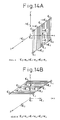
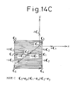
- Figures 14A, 14B, and 14C are views showing the distributions of the code vectors virtually formed in the codebook (mode A, mode B, and mode C). For example, considering three vectors, that is, C 0 , ⁇ C 1 , and ⁇ C 2 , there are six types of distribution of the vectors (mode A to mode F).
- Figure 14A to Fig. 14C show mode A to mode C, respectively.
- e x , e y , and e z indicate unit vectors in the x-axial, y-axial, and z-axial directions constituting the three dimensions.
- the remaining modes D, E, and F correspond to allocations of the following unit vectors to the vectors:
- delta vector codebooks 11 with different distributions of modes depending on the order of the vectors given as delta vectors. That is, if the order of the delta vectors is allotted in a fixed manner at all times as shown in Fig. 13, then only code vectors constantly biased toward a certain mode can be reproduced and there is no guarantee that the optimal speech coding will be performed on the input speech signal AX covered by the vector quantization. That is, there is a danger of an increase in the quantizing distortion.
- the mode of the distribution of the code vectors virtually created in the codebook 1 may be adjusted. That is, the properties of the codebook may be changed.
- the mode of the distribution of the code vectors may be adjusted to match the properties of the input speech signal to be coded. This enables a further improvement of the quality of the reproduced speech.
- the vectors are rearranged for each frame in accordance with the properties of the linear prediction analysis (LPC) filter 3. If this is done, then at the side receiving the speech coding data, that is, the decoding side, it is possible to perform the exact same adjustment (rearrangement of the vectors) as performed at the coder side without sending special adjustment information from the coder side.
- LPC linear prediction analysis
- the powers of the filter outputs of the vectors obtained by applying linear prediction analysis filter processing on the initial vector and delta vectors are evaluated and the vectors are rearranged in the order of the initial vector, the first delta vector, the second delta vector. successively from the vectors with the greater increase in power compared with the power before the filter processing.
- the vectors are transformed in advance so that the initial vector and the delta vectors are mutually orthogonal after the linear prediction analysis filter processing.
- the vectors are transformed in advance so that the initial vector and the delta vectors are mutually orthogonal after the linear prediction analysis filter processing.
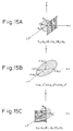
- Figures 15A, 15B, and 15C are views for explaining the rearrangement of the vectors based on the modified second embodiment.
- the ball around the origin of the coordinate system (hatched) is the space of all the vectors defined by the unit vectors e x , e y , and e z . If provisionally the unit vector e x is allotted to the initial vector C 0 and the unit vectors e y and e z are allotted to the first delta vector ⁇ C 1 and the second delta vector ⁇ C 2 , the planes defined by these become planes including the normal at the point C 0 on the ball. This corresponds to the mode A (Fig. 14A).
- the properties A of the linear prediction analysis filter 3 show different amplitude amplification properties with respect to the vectors constituting the delta vector codebook 11, so it is better that all the vectors virtually created in the codebook 11 be distributed nonuniformly rather than uniformly through the vector space. Therefore, if it is investigated which direction of vector component is amplified the most and the distribution of that direction of vector component is increased, it becomes possible to store the vectors efficiently in the codebook 11 and as a result the quantization characteristics of the speech signals become improved.
- the vectors are rearranged in order from the delta vector ( ⁇ C 2 ) with the largest power, then the codebook vectors are produced in accordance with the tree-structure array once more.
- a delta vector codebook 11 for coding, it is possible to improve the quality of the reproduced speech compared with the fixed allotment and arrangment of delta vectors as in the above-mentioned second embodiment.
- Figure 16 is a view showing one example of the portion of the codebook retrieval processing based on the modified second embodiment. It shows an example of the rearrangement shown in Figs. 15A, 15, and 15C. It corresponds to a modification of the structure of Fig. 12 (second embodiment) mentioned earlier.
- the power evaluation unit 41 and the sorting unit 42 are cooperatively incorporated into the memory unit 31.
- the power evaluation unit 41 evaluates the power of the initial vector and the delta vectors after filter processing by the linear filter analysis filter 3.
- the sorting unit 42 rearranges the order of the vectors.
- the power evaluation unit 41 and the sorting unit 42 may be explained as follows with reference to the above-mentioned Figs. 14A to 14C and Figs. 15A to 15C.
- the powers of the vectors (A C 0 , A ⁇ C 1 , and A ⁇ C 2 ) obtained by linear prediction analysis filter processing of the vectors ( C 0 , ⁇ C 1 , and ⁇ C 2 ) stored in the delta vector codebook 11 are calculated.
- a direction comparison of the powers after filter processing would mean a comparison of the amplitude amplification factors of the vectors (see following (2)).
- the amplitude amplification factors of the vectors by the analysis filter (A) are received from the power evaluation unit 41 and the vectors are rearranged (sorted) in the order of the largest amplification factors down.
- new delta vectors are set in the order of the largest amplification factors down, such as the initial vector ( C 0 ), the first delta vector ( ⁇ C 1 ), the second delta vector ( ⁇ C 2 )...
- the following coding processing is performed in exactly the same way as the case of the tree-structure delta codebook of Fig. 12 using the tree-structure delta codebook 11 comprised by the obtained delta vectors. Below, the sorting processing in the case shown in Figs. 15A to 15C will be shown.
- the above-mentioned second embodiment and modified second embodiment may be applied to any of the sequential optimization CELP type speech coder and simultaneous CELP type speech coder or pitch orthogonal transformation optimization CELP type speech coder etc.
- the method of application is the same as with the use of the cyclic adding means 20 (14, 15; 16, 17, 14-1, 15-1; 14-2, 15-2) explained in detail in the first embodiment.
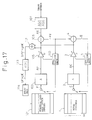
- Figure 17 is a view showing a coder of the sequential optimization CELP type
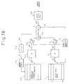
- Fig. 18 is a view showing a coder of the simultaneous optimization CELP type. Note that constituent elements previously mentioned are given the same reference numerals or symbols.
- the adaptive codebook 101 stores N dimensional pitch prediction residual vectors corresponding to the N samples delayed in pitch period one sample each. Further, the codebook 1 has set in it in advance, as mentioned earlier, exactly 2 m patterns of code vectors produced using the N dimensional noise trains corresponding to the N samples. Preferably, sample data with an amplitude less than a certain threshold (for example, N/4 samples out of N samples) out of the sample data of the code vectors are replaced by 0.
- a certain threshold for example, N/4 samples out of N samples
- the perceptually weighted pitch prediction error signal vectors A Y between the pitch prediction reproduced signal vectors bA P and the input speech signal vector A X perceptually weighted by the perceptual weighting filter 107 shown by A(z)/A'(z) (where A'(z) shows a linear prediction analysis filter) are found by the subtraction unit 108.
- the optimal pitch predition differential vector P is selected and the optimal gain b is selected by the following equation
- 2
- the perceptually weighted reproduced code vectors A C produced by perceptual weighting by the linear prediction analysis filter 3 in the same way as the code vectors C of the codebook 1 are multiplied with the gain 2 by the amplifier 2 so as to produce the linear prediction reproduced signal vectors gA C .
- the amplifier 2 may be positioned before the filter 3 as well.
- the error signal vectors E of the linear prediction reproduced signal vectors gA C and the above-mentioned pitch prediction error signal vectors A Y are found by the error generation unit 4 and the optical code vector C is selected from the codebook 1 and the optimal gain g is selected with each frame by the evaluation unit 5 so as to give the minimum power of the error signal vector E by the following:
- 2
- the adaptation of the adaptive codebook 101 is performed by finding bA P +gA C by the adding unit 112, analyzing this to b P +g C by the perceptual weighting linear prediction analysis filter (A'(z)) 113, giving a delay of one frame by the delay unit 114, and storing the result as the adaptive codebook (pitch prediction codebook) of the next frame.
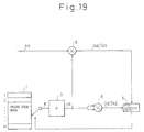
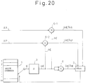
- the gains b and g shown in concept in the above Fig. 17 and Fig. 18 actually perform the optimization for the code vector C of the codebook 1 in the respective CELP systems as shown in Fig. 19 and Fig. 20.
- the pitch prediction error signal vector A Y and the code vectors A C obtained by passing the code vectors C of the codebook 1 through the perceptual weighting linear prediction analysis filter 3 are multiplied by the multiplying unit 6 to produce the correlation values (A C ) T A Y of the two and the auto correlation values (A C ) T A C of the perceptually weighted reproduced code vectors A C are found by the auto correlation computation unit 8.
- the evaluation unit 5 selects the optimal code vector C and gain g giving the minimum power of the error signal vectors E with respect to the pitch prediction error signal vectors A Y by the above-mentioned equation (28) based on the two correlation values (A C ) T A Y and (A C ) T A C .
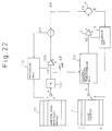
- the perceptually weighted input speech signal vector A X and the code vectors A C obtained by passing the code vectors C of the codebook 1 through the perceptual weighting linear prediction analysis filter 3 are multiplied by the multiplying unit 6-1 to produce the correlation values (A C ) T A X of the two, the perceptually weighted pitch prediction vectors A P and the code vectors A C are multiplied by the multiplying unit 6-2 to produce the cross correlations (A C ) T A P of the two, and the auto correlation values (A C ) T of the code vectors A C are found by the auto correlation computation unit 8.
- the evaluation unit 5 selects the optimal code vector C and gains b and g giving the minimum power of the error signal vectors E with respect to the perceptually weighted input speech signal vectors A X by the above-mentioned equation (29) based on the correlation values (A C ) T A X , (A C ) T A P , and (A C ) T A C .
- minimizing the power of the vector E is equivalent to maximizing the ratio of the correlation value 2b(AP) T AX-b 2 (AP) T AP+2g(AC) T AX-g 2 (AC) T AC-2bg(AP) T AC
- the sequential optimization CELP system less of an overall amount of computation is needed compared with the simultaneous optimization CELP system, but the quality of the coded speech is deteriorated.
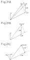
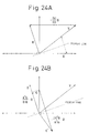
- Figure 21A is a vector diagram showing schematically the gain optimization operation in the case of the sequential optimization CELP system
- Fig. 21B is a vector diagram showing schematically the gain optimization operation in the case of the simultaneous CELP system
- Fig. 21C is a vector diagram showing schematically the gain optimization operation in the case of the pitch orthogonal tranformation optimization CELP system.
- the pitch prediction differential vector P and the gain b are evaluated and selected in the same way as in the past, but regarding the code vector C and the gain g, the weighted orthogonal transformation unit 50 is provided and the code vectors C of the codebook 1 are transformed into the perceptually weighted reproduced code vectors A C ' orthogonal to the optimal pitch prediction differential vector A P in the perceptually weighted pitch prediction differential vectors.
- the thus obtained code vector A C ' is multiplied with the gain g to produce the linear prediction reproduced signal gA C ', the code vector giving the minimum linear prediction error signal vector E from the linear prediction reproduced signals gA C ' and the perceptually weighted input speech signal vectors A X is selected by the evaluation unit 5 from the codebook 1, and the gain g is selected.
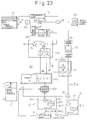
- Figure 23 is a view showing in more detail the portion of the codebook retrieval processing under the first embodiment using still another example. It shows the case of application to the above-mentioned pitch orthogonal transformation optimization CELP type speech coder. In this case too, the present invention may be applied without any obstacle.
- This Fig. 23 shows an example of the combination of the auto correlation computation unit 13 of Fig. 10 with the structure shown in Fig. 9. Further, the computing means 19' shown in Fig. 9 may be constructed by the transposed matrix A T in the same way as the computing means 19 of Fig. 6, but in this example is constructed by a time-reverse type filter.
- the auto correlation computing means 60 of the figure is comprised of the computation units 60a to 60e.
- This vector V is transformed into three vectors B , u B , and A B in the computation unit 60b which receives as input the vectors D orthogonal to all the delta vectors ⁇ C in the delta vector codebook 11 and applies perceptual weighting filter (A) processing to the same.
- the thus obtained D direction vector is taken as 1(
- the vector B V -(
- FIR finite impulse response
- ⁇ C the delta vectors ⁇ C are given to the computation unit 60d from the codebook 11
- ( ⁇ C i ) T GC i-1 +( ⁇ C i ) T G ⁇ C i is obtained.
- This is cyclically added with the previous auto correlation value (AH C i-1 ) T AH C i-1 at the cyclic adding unit 60e (cyclic computing means 20), thereby enabling the present auto correlation value of (AH C i ) T AH C i to be found and sent to the evaluation unit 5.
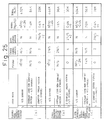
- Figure 25 is a view showing the ability to reduce the amount of computation by the first embodiment of the present invention.
- Section (a) of the figure shows the case of a sequential optimization CELP type coder and shows the amount of computation in the cases of use of
- N in Fig. 25 is the number of samples
- N P is the number of orders of the filter 3.
- the total amount of computations becomes 432 K multiplication and accumulation operations in the conventional example (1) and 84 K multiplication and accumulation operations in the conventional example (2).
- 28 K multiplication and accumulation operations are required, for a major reduction.
- Section (b) and section (c) of Fig. 25 show the case of a simultaneous optimization CELP type coder and a pitch orthogonal transformation optimization CELP type coder.
- the amounts of computation are calculated for the cases of the three types of codebooks just as in the case of section (a). In either of the cases, in the case of application of the first embodiment of the present invention, the amount of computation can be reduced tremendously to 30 K multiplication and accumulation operations or 28 K multiplication and accumulation operations, it is learned.
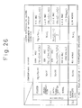
- Figure 26 is a view showing the ability to reduce the amount of computation and to slash the memory size by the second embodiment of the present invention. Section (a) of the figure shows the amount of computations and section (b) the size of the memory of the codebook.
- the number of samples N of the code vectors is made a standard N of 40. Further, as the size M of the codebook, the standard M of 1024 is used is used in the conventional system, but the size M of the second embodiment of the present invention is reduced to L, specifically with L being made 10. This L is the same as the number of layers 1, 2, 3... L shown at the top of Fig. 11.
- the 480K multiplication and accumulation operations (96 M ops ) required in the conventional system are slashed to about 1/70th that amount, of 6.6 K multiplication and accumulation operations, in the second embodiment of the present invention.
- a look at the size of the memory (section (b)) in Fig. 26 shows it reduced to 1/100th the previous size.
- the total amount of the computations including the filter processing computation, accounting for the majority of the computations, the computation of the auto correlations, and the computation of the cross correlations, is slashed in the same way as the value shown in Fig. 26.
- the present invention may be applied to transmission systems in cellular telephones and car telephones, in particular to speech coders for transmitting input speech as digital data to receiver systems.
Claims (18)
- Système de codage de parole dans lequel la parole d'entrée est codée en trouvant par un calcul d'évaluation un vecteur de code unique donnant une erreur minimum entre des signaux reproduits obtenus par un traitement de filtre d'analyse de prédiction linéaire, en simulant des caractéristiques de chemin de parole, sur des vecteurs de code successivement extraits d'un livre de code de bruit stockant une pluralité de trains de bruit comme vecteurs de code (C0, C1, C2, ...) et un signal de parole d'entrée et en utilisant un code spécifiant lesdits vecteurs de code,ledit système de codage de parole caractérisé en ce que :ledit livre de code de bruit est composé par un livre de code de vecteur delta (11) qui stocke un vecteur initial (C0) et une pluralité de vecteurs delta (ΔC) obtenu en trouvant les vecteurs différentiels entre des vecteurs de code contigus pour tous les vecteurs de code etlesdits vecteurs delta sont cycliquement additionnés afin de reproduire virtuellement lesdits vecteurs de code (C0, C1, C2, ...).
- Système de codage de parole selon la revendication 1, dans lequel lesdits vecteurs delta sont N vecteurs dimensionnels composés de N nombre (N étant un nombre naturel de 2 ou plus) de données d'échantillon de série temporelle, plusieurs des données d'échantillon parmi les N nombre de données d'échantillon sont des données significatives (Δ1, Δ2, Δ3, et Δ1), et le reste sont des vecteurs clairsemés composés de 0 de données.
- Système de codage de parole selon la revendication 2, dans lequel les vecteurs de code (C0, C1, C2, ...) dans ledit livre de code de bruit sont réarrangés pour que les vecteurs différentiels entre les vecteurs de code contigus deviennent plus petit, des vecteurs différentiels entre les vecteurs de code contigus sont trouvés pour les vecteurs de code réarrangés, et lesdits vecteurs dispersés sont ainsi obtenus.
- Système de codage de parole selon la revendication 1, dans lequel un moyen d'addition cyclique (20) pour réaliser l'addition cyclique susmentionnée est fourni comme partie du moyen de calcul pour ledit calcul d'évaluation.
- Système de codage de parole selon la revendication 4, dans lequel ledit moyen d'addition cyclique (20) est composé d'unité d'addition (14, 14-1, 14-2) pour additionner les données de calcul et des unités à retard (16, 16-1, 16-2) pour donner un retard aux sorties des unités d'addition et les retourner à une entrée des unités d'addition, les résultats précédents de calcul sont maintenus dans lesdites unités à retard, le vecteur delta donné suivant est utilisé comme entrée, et le résultat de calcul est donc mis à jour cumulativement.
- Système de codage de parole selon la revendication 1, dans lequel la pluralité de vecteurs delta (ΔC) sont exprimés par (L-1) types de vecteurs delta disposés dans une structure en arbre, où L est le nombre total de couches constituant la structure en arbre avec ledit vecteur initial (C0) sur sa crête.
- Système de codage de parole selon la revendication 6, dans lequel lesdits (L-1) types des vecteurs delta sont successivement additionnés ou soustraits dudit vecteur initial (C0) avec chaque couche afin de reproduire virtuellement (2L-1) types de vecteurs de code.
- Système de codage de parole selon la revendication 7, dans lequel des vecteurs de zéro sont ajoutés audits (2L-1) types des vecteurs de code afin de reproduire le même nombre de vecteurs de code que les deux 2L types de vecteurs de code stockés dans ledit livre de code de bruit.
- Système de codage de parole selon la revendication 7, dans lequel ledit vecteur de code (-C0) obtenu en multipliant ledit vecteur initial (C0) par -1 est ajouté audit (2L-1) types de vecteurs de code pour reproduire le même nombre de vecteurs de code que lesdits (2L) types de vecteurs de code stockés dans ledit livre de code de bruit.
- Système de codage de parole selon la revendication 6, dans lequel un moyen cyclique (20) pour réaliser ladite addition cyclique est fourni comme partie dudit moyen de calcul pour ledit calcul d'évaluation.
- Système de codage de parole selon la revendication 10, dans lequel ledit calcul d'évaluation comprend le calcul de l'intercorrélation et le calcul de filtre d'analyse de prédiction linéaire et la sortie de calcul de filtre d'analyse (AC) est exprimé par une équation de récurrence utilisant la sortie de calcul du filtre d'analyse d'une couche avant et le présent vecteur delta, de sorte que ledit calcul de l'intercorrélation est exprimé comme une équation de récurrence.
- Système de codage de parole selon la revendication 11, dans lequel ledit calcul d'évaluation comprend le calcul d'autocorrélation et la sortie de calcul de filtre d'analyse (AC) est exprimée par une équation de récurrence utilisant la sortie de calcul de filtre d'analyse d'une couche avant et le présent vecteur delta, de sorte que ledit calcul d'autocorrélation est exprimé en utilisant le nombre L total d'autocorrélation de la sortie de calcul du filtre d'analyse dudit vecteur initial (C0) et la sortie de calcul de filtre desdits (L-1) types de vecteurs delta et les (L2-1)/2 types d'intercorrélation parmi les sorties de calcul de filtre d'analyse.
- Système de codage de parole selon la revendication 6, dans lequel l'ordre dudit vecteur initial (C0) et lesdits (L-1) types de vecteur delta (ΔC) dans ledit réseau de structure en arbre est changé selon les propriétés dudit signal de parole d'entrée pour réarranger le vecteur initial et les vecteurs delta.
- Système de codage de parole selon la revendication 13, dans lequel ledit vecteur initial et les vecteurs delta sont disposés avec chaque trame selon les propriétés de filtre (3) pour réaliser le calcul de filtre d'analyse de prédiction linéaire, un desdits calculs d'évaluation.
- Système de codage de parole selon la revendication 14, dans lequel la puissance desdits signaux reproduits obtenus à partir dudit filtre (3) sont évalués par ledit calcul d'évaluation et les vecteurs sont réarrangés dans le nouvel ordre du vecteur initial (C0) → premier vecteur delta (ΔC1) → second vecteur delta (ΔC2) successivement à partir du vecteur avec la puissance la plus accrue comparée à la puissance avant ledit traitement de filtre.
- Système de codage de parole selon la revendication 15, dans lequel ledit vecteur initial (C0) et des vecteurs delta (ΔC) sont transformés à l'avance afin d'être mutuellement orthogonaux après ledit traitement de filtre pour que tous les vecteurs dans ledit livre de code de vecteur delta (11) soient uniformément distribués sur un hyper plan.
- Système de codage de parole selon la revendication 15, dans lequel les intensités de puissance sont comparées grâce à la puissance normalisée obtenue par la normalisation desdites puissances.
- Système de codage de parole selon la revendication 13, dans lequel lorsque l'attribution desdits codes spécifiant lesdits vecteurs de code, les codes sont attribués pour que la distance intercode appartenant aux couches les plus élevées dans ledit réseau de vecteur à structure en arbre devienne plus grande que la distance intercode appartenant aux couches inférieures.
Applications Claiming Priority (5)
| Application Number | Priority Date | Filing Date | Title |
|---|---|---|---|
| JP244174/90 | 1990-09-14 | ||
| JP24417490 | 1990-09-14 | ||
| JP3127669A JPH04352200A (ja) | 1991-05-30 | 1991-05-30 | 音声符号化方式 |
| JP127669/91 | 1991-05-30 | ||
| PCT/JP1991/001235 WO1992005541A1 (fr) | 1990-09-14 | 1991-09-17 | Systeme de codage de la parole |
Publications (3)
| Publication Number | Publication Date |
|---|---|
| EP0500961A1 EP0500961A1 (fr) | 1992-09-02 |
| EP0500961A4 EP0500961A4 (fr) | 1995-01-11 |
| EP0500961B1 true EP0500961B1 (fr) | 1998-04-29 |
Family
ID=26463564
Family Applications (1)
| Application Number | Title | Priority Date | Filing Date |
|---|---|---|---|
| EP91915981A Expired - Lifetime EP0500961B1 (fr) | 1990-09-14 | 1991-09-17 | Systeme de codage de la parole |
Country Status (6)
| Country | Link |
|---|---|
| US (1) | US5323486A (fr) |
| EP (1) | EP0500961B1 (fr) |
| JP (1) | JP3112681B2 (fr) |
| CA (1) | CA2068526C (fr) |
| DE (1) | DE69129329T2 (fr) |
| WO (1) | WO1992005541A1 (fr) |
Families Citing this family (35)
| Publication number | Priority date | Publication date | Assignee | Title |
|---|---|---|---|---|
| JP3077944B2 (ja) * | 1990-11-28 | 2000-08-21 | シャープ株式会社 | 信号再生装置 |
| WO1992011627A2 (fr) * | 1990-12-21 | 1992-07-09 | British Telecommunications Public Limited Company | Codage de signaux vocaux |
| US5671327A (en) * | 1991-10-21 | 1997-09-23 | Kabushiki Kaisha Toshiba | Speech encoding apparatus utilizing stored code data |
| US5864650A (en) * | 1992-09-16 | 1999-01-26 | Fujitsu Limited | Speech encoding method and apparatus using tree-structure delta code book |
| IT1257431B (it) * | 1992-12-04 | 1996-01-16 | Sip | Procedimento e dispositivo per la quantizzazione dei guadagni dell'eccitazione in codificatori della voce basati su tecniche di analisi per sintesi |
| CA2102080C (fr) * | 1992-12-14 | 1998-07-28 | Willem Bastiaan Kleijn | Decalage temporel pour le codage generalise d'analyse par synthese |
| JP2591430B2 (ja) * | 1993-06-30 | 1997-03-19 | 日本電気株式会社 | ベクトル量子化装置 |
| JP2626492B2 (ja) * | 1993-09-13 | 1997-07-02 | 日本電気株式会社 | ベクトル量子化装置 |
| US5462879A (en) * | 1993-10-14 | 1995-10-31 | Minnesota Mining And Manufacturing Company | Method of sensing with emission quenching sensors |
| CA2137756C (fr) * | 1993-12-10 | 2000-02-01 | Kazunori Ozawa | Codeur vocal et methode de recherche d'impulsions d'excitation |
| JPH07168913A (ja) * | 1993-12-14 | 1995-07-04 | Chugoku Nippon Denki Software Kk | 文字認識システム |
| JP3119063B2 (ja) * | 1994-01-11 | 2000-12-18 | 富士通株式会社 | 符号情報処理方式並びにその符号装置及び復号装置 |
| JP2956473B2 (ja) * | 1994-04-21 | 1999-10-04 | 日本電気株式会社 | ベクトル量子化装置 |
| US5704003A (en) * | 1995-09-19 | 1997-12-30 | Lucent Technologies Inc. | RCELP coder |
| JPH11513813A (ja) * | 1995-10-20 | 1999-11-24 | アメリカ オンライン インコーポレイテッド | 反復的な音の圧縮システム |
| AU767779B2 (en) * | 1995-10-20 | 2003-11-27 | Facebook, Inc. | Repetitive sound compression system |
| JP3707116B2 (ja) * | 1995-10-26 | 2005-10-19 | ソニー株式会社 | 音声復号化方法及び装置 |
| JP3680380B2 (ja) * | 1995-10-26 | 2005-08-10 | ソニー株式会社 | 音声符号化方法及び装置 |
| TW317051B (fr) * | 1996-02-15 | 1997-10-01 | Philips Electronics Nv | |
| DE69732746C5 (de) * | 1996-02-15 | 2020-11-19 | Koninklijke Philips N.V. | Signalübertragungssystem mit verringerter komplexität |
| US6038528A (en) * | 1996-07-17 | 2000-03-14 | T-Netix, Inc. | Robust speech processing with affine transform replicated data |
| US6192336B1 (en) * | 1996-09-30 | 2001-02-20 | Apple Computer, Inc. | Method and system for searching for an optimal codevector |
| US6161086A (en) * | 1997-07-29 | 2000-12-12 | Texas Instruments Incorporated | Low-complexity speech coding with backward and inverse filtered target matching and a tree structured mutitap adaptive codebook search |
| US6173257B1 (en) * | 1998-08-24 | 2001-01-09 | Conexant Systems, Inc | Completed fixed codebook for speech encoder |
| US6556966B1 (en) * | 1998-08-24 | 2003-04-29 | Conexant Systems, Inc. | Codebook structure for changeable pulse multimode speech coding |
| US6493665B1 (en) * | 1998-08-24 | 2002-12-10 | Conexant Systems, Inc. | Speech classification and parameter weighting used in codebook search |
| US6480822B2 (en) | 1998-08-24 | 2002-11-12 | Conexant Systems, Inc. | Low complexity random codebook structure |
| US6714907B2 (en) | 1998-08-24 | 2004-03-30 | Mindspeed Technologies, Inc. | Codebook structure and search for speech coding |
| US6823303B1 (en) * | 1998-08-24 | 2004-11-23 | Conexant Systems, Inc. | Speech encoder using voice activity detection in coding noise |
| US6212496B1 (en) | 1998-10-13 | 2001-04-03 | Denso Corporation, Ltd. | Customizing audio output to a user's hearing in a digital telephone |
| US6850884B2 (en) * | 2000-09-15 | 2005-02-01 | Mindspeed Technologies, Inc. | Selection of coding parameters based on spectral content of a speech signal |
| US6842733B1 (en) | 2000-09-15 | 2005-01-11 | Mindspeed Technologies, Inc. | Signal processing system for filtering spectral content of a signal for speech coding |
| CN1202514C (zh) * | 2000-11-27 | 2005-05-18 | 日本电信电话株式会社 | 编码和解码语音及其参数的方法、编码器、解码器 |
| CN1898724A (zh) * | 2003-12-26 | 2007-01-17 | 松下电器产业株式会社 | 语音/乐音编码设备及语音/乐音编码方法 |
| KR20080052813A (ko) * | 2006-12-08 | 2008-06-12 | 한국전자통신연구원 | 채널별 신호 분포 특성을 반영한 오디오 코딩 장치 및 방법 |
Family Cites Families (7)
| Publication number | Priority date | Publication date | Assignee | Title |
|---|---|---|---|---|
| JPS61237519A (ja) * | 1985-04-12 | 1986-10-22 | Mitsubishi Electric Corp | フレ−ム間適応ベクトル量子化符号化装置 |
| JPS63240600A (ja) * | 1987-03-28 | 1988-10-06 | 松下電器産業株式会社 | ベクトル量子化方法 |
| US4868867A (en) * | 1987-04-06 | 1989-09-19 | Voicecraft Inc. | Vector excitation speech or audio coder for transmission or storage |
| CA1337217C (fr) * | 1987-08-28 | 1995-10-03 | Daniel Kenneth Freeman | Codage vocal |
| DE3871369D1 (de) * | 1988-03-08 | 1992-06-25 | Ibm | Verfahren und einrichtung zur sprachkodierung mit niedriger datenrate. |
| JPH0365822A (ja) * | 1989-08-04 | 1991-03-20 | Fujitsu Ltd | ベクトル量子化符号器及びベクトル量子化復号器 |
| US5144671A (en) * | 1990-03-15 | 1992-09-01 | Gte Laboratories Incorporated | Method for reducing the search complexity in analysis-by-synthesis coding |
-
1991
- 1991-09-17 DE DE69129329T patent/DE69129329T2/de not_active Expired - Fee Related
- 1991-09-17 CA CA002068526A patent/CA2068526C/fr not_active Expired - Fee Related
- 1991-09-17 WO PCT/JP1991/001235 patent/WO1992005541A1/fr active IP Right Grant
- 1991-09-17 EP EP91915981A patent/EP0500961B1/fr not_active Expired - Lifetime
- 1991-09-17 US US07/856,221 patent/US5323486A/en not_active Expired - Lifetime
- 1991-09-17 JP JP03515016A patent/JP3112681B2/ja not_active Expired - Fee Related
Also Published As
| Publication number | Publication date |
|---|---|
| JP3112681B2 (ja) | 2000-11-27 |
| CA2068526A1 (fr) | 1992-03-15 |
| CA2068526C (fr) | 1997-02-25 |
| US5323486A (en) | 1994-06-21 |
| DE69129329T2 (de) | 1998-09-24 |
| DE69129329D1 (de) | 1998-06-04 |
| WO1992005541A1 (fr) | 1992-04-02 |
| EP0500961A4 (fr) | 1995-01-11 |
| EP0500961A1 (fr) | 1992-09-02 |
Similar Documents
| Publication | Publication Date | Title |
|---|---|---|
| EP0500961B1 (fr) | Systeme de codage de la parole | |
| EP0443548B1 (fr) | Codeur de parole | |
| US4868867A (en) | Vector excitation speech or audio coder for transmission or storage | |
| US6510407B1 (en) | Method and apparatus for variable rate coding of speech | |
| Paliwal et al. | Efficient vector quantization of LPC parameters at 24 bits/frame | |
| JP3114197B2 (ja) | 音声パラメータ符号化方法 | |
| JP4743963B2 (ja) | 複数チャネル信号の符号化及び復号化 | |
| US7065338B2 (en) | Method, device and program for coding and decoding acoustic parameter, and method, device and program for coding and decoding sound | |
| EP0476614A2 (fr) | Système de codage et de décodage de parole | |
| KR100194775B1 (ko) | 벡터양자화장치 | |
| JP3435674B2 (ja) | 信号の符号化方法と復号方法及びそれを使った符号器及び復号器 | |
| WO2001020595A1 (fr) | Codeur/decodeur vocal | |
| EP0462558B1 (fr) | Méthode de codage de la parole | |
| US20050114123A1 (en) | Speech processing system and method | |
| EP0778561B1 (fr) | Dispositif de codage de la parole | |
| US7680669B2 (en) | Sound encoding apparatus and method, and sound decoding apparatus and method | |
| KR100465316B1 (ko) | 음성 부호화기 및 이를 이용한 음성 부호화 방법 | |
| US5884252A (en) | Method of and apparatus for coding speech signal | |
| CN100367347C (zh) | 话音信号编码器和话音信号解码器 | |
| JP3916934B2 (ja) | 音響パラメータ符号化、復号化方法、装置及びプログラム、音響信号符号化、復号化方法、装置及びプログラム、音響信号送信装置、音響信号受信装置 | |
| JP3579276B2 (ja) | 音声符号化/復号化方法 | |
| JP2943983B1 (ja) | 音響信号の符号化方法、復号方法、そのプログラム記録媒体、およびこれに用いる符号帳 | |
| EP0780832A2 (fr) | Dispositif pour estimer l'écart des enveloppes de puissance de signaux synthétiques par rapport aux signaux d'entrée dans un codeur de parole | |
| JP3092436B2 (ja) | 音声符号化装置 | |
| JP3010655B2 (ja) | 圧縮符号化装置及び方法、並びに復号装置及び方法 |
Legal Events
| Date | Code | Title | Description |
|---|---|---|---|
| PUAI | Public reference made under article 153(3) epc to a published international application that has entered the european phase |
Free format text: ORIGINAL CODE: 0009012 |
|
| 17P | Request for examination filed |
Effective date: 19920514 |
|
| AK | Designated contracting states |
Kind code of ref document: A1 Designated state(s): DE FR GB |
|
| A4 | Supplementary search report drawn up and despatched | ||
| AK | Designated contracting states |
Kind code of ref document: A4 Designated state(s): DE FR GB |
|
| GRAG | Despatch of communication of intention to grant |
Free format text: ORIGINAL CODE: EPIDOS AGRA |
|
| 17Q | First examination report despatched |
Effective date: 19970704 |
|
| GRAG | Despatch of communication of intention to grant |
Free format text: ORIGINAL CODE: EPIDOS AGRA |
|
| GRAH | Despatch of communication of intention to grant a patent |
Free format text: ORIGINAL CODE: EPIDOS IGRA |
|
| GRAH | Despatch of communication of intention to grant a patent |
Free format text: ORIGINAL CODE: EPIDOS IGRA |
|
| GRAA | (expected) grant |
Free format text: ORIGINAL CODE: 0009210 |
|
| AK | Designated contracting states |
Kind code of ref document: B1 Designated state(s): DE FR GB |
|
| REF | Corresponds to: |
Ref document number: 69129329 Country of ref document: DE Date of ref document: 19980604 |
|
| ET | Fr: translation filed | ||
| PLBE | No opposition filed within time limit |
Free format text: ORIGINAL CODE: 0009261 |
|
| STAA | Information on the status of an ep patent application or granted ep patent |
Free format text: STATUS: NO OPPOSITION FILED WITHIN TIME LIMIT |
|
| 26N | No opposition filed | ||
| REG | Reference to a national code |
Ref country code: GB Ref legal event code: IF02 |
|
| PGFP | Annual fee paid to national office [announced via postgrant information from national office to epo] |
Ref country code: FR Payment date: 20060908 Year of fee payment: 16 |
|
| PGFP | Annual fee paid to national office [announced via postgrant information from national office to epo] |
Ref country code: GB Payment date: 20060913 Year of fee payment: 16 |
|
| PGFP | Annual fee paid to national office [announced via postgrant information from national office to epo] |
Ref country code: DE Payment date: 20060914 Year of fee payment: 16 |
|
| GBPC | Gb: european patent ceased through non-payment of renewal fee |
Effective date: 20070917 |
|
| PG25 | Lapsed in a contracting state [announced via postgrant information from national office to epo] |
Ref country code: DE Free format text: LAPSE BECAUSE OF NON-PAYMENT OF DUE FEES Effective date: 20080401 |
|
| REG | Reference to a national code |
Ref country code: FR Ref legal event code: ST Effective date: 20080531 |
|
| PG25 | Lapsed in a contracting state [announced via postgrant information from national office to epo] |
Ref country code: FR Free format text: LAPSE BECAUSE OF NON-PAYMENT OF DUE FEES Effective date: 20071001 |
|
| PG25 | Lapsed in a contracting state [announced via postgrant information from national office to epo] |
Ref country code: GB Free format text: LAPSE BECAUSE OF NON-PAYMENT OF DUE FEES Effective date: 20070917 |