EP0500768B1 - Hinged centrifuge tube adapter - Google Patents
Hinged centrifuge tube adapter Download PDFInfo
- Publication number
- EP0500768B1 EP0500768B1 EP91900113A EP91900113A EP0500768B1 EP 0500768 B1 EP0500768 B1 EP 0500768B1 EP 91900113 A EP91900113 A EP 91900113A EP 91900113 A EP91900113 A EP 91900113A EP 0500768 B1 EP0500768 B1 EP 0500768B1
- Authority
- EP
- European Patent Office
- Prior art keywords
- adapter
- tube
- segments
- segment
- rotor
- Prior art date
- Legal status (The legal status is an assumption and is not a legal conclusion. Google has not performed a legal analysis and makes no representation as to the accuracy of the status listed.)
- Expired - Lifetime
Links
Images


Classifications
-
- B—PERFORMING OPERATIONS; TRANSPORTING
- B04—CENTRIFUGAL APPARATUS OR MACHINES FOR CARRYING-OUT PHYSICAL OR CHEMICAL PROCESSES
- B04B—CENTRIFUGES
- B04B5/00—Other centrifuges
- B04B5/04—Radial chamber apparatus for separating predominantly liquid mixtures, e.g. butyrometers
- B04B5/0407—Radial chamber apparatus for separating predominantly liquid mixtures, e.g. butyrometers for liquids contained in receptacles
- B04B5/0414—Radial chamber apparatus for separating predominantly liquid mixtures, e.g. butyrometers for liquids contained in receptacles comprising test tubes
-
- B—PERFORMING OPERATIONS; TRANSPORTING
- B04—CENTRIFUGAL APPARATUS OR MACHINES FOR CARRYING-OUT PHYSICAL OR CHEMICAL PROCESSES
- B04B—CENTRIFUGES
- B04B5/00—Other centrifuges
- B04B5/04—Radial chamber apparatus for separating predominantly liquid mixtures, e.g. butyrometers
- B04B5/0407—Radial chamber apparatus for separating predominantly liquid mixtures, e.g. butyrometers for liquids contained in receptacles
- B04B2005/0435—Radial chamber apparatus for separating predominantly liquid mixtures, e.g. butyrometers for liquids contained in receptacles with adapters for centrifuge tubes or bags
Definitions
- the present invention relates to an adapter for holding a centrifuge tube in a centrifuge rotor cavity, and in particular, to an adapter having two segments.
- a device known as a tube adapter When the shape and size of a centrifuge tube does not closely conform to the shape and size of the rotor cavity in which it is to be disposed a device known as a tube adapter is usually employed.
- the tube adapter has an interior cavity having a shape and size which closely conforms to the shape and size of the centrifuge tube being adapted.
- the exterior shape and size of the adapter closely conforms to the shape and size of the rotor cavity in which is is to be used.
- the adapter serves to support a tube within the cavity in which it is received and thus serves to prevent deformation of the tube during centrifugation.
- an adapter formed of a single unitary member is the device disclosed in United States Patent 4,304,356 (Chulay et al.). This adapter supports only the neck region of the centrifuge tube and is fabricated of a material having a lower density than the liquid being carried therein to prevent bottoming of the adapter in the rotor cavity in the event of tube rupture.
- an adapter formed of two piece construction is the device shown in United States Patent 3,674,197 (Mitchell et al.), assigned to the assignee of this invention.
- This adapter comprises two discrete segments, each of which has an indentation therein. When joined the indentations form a recess for receiving a collapsible bag during centrifugation.
- the adapter disclosed in this patent includes aperture(s) through which tubes from the bag exit the adapter. Thus, the possibility exists that the bag may extrude through these apertures if the adapter were to undergo centrifugation in a vertical angle rotor.
- the adapter segments support the neck region of the centrifuge tube. It is composed of two discrete adapter segments which support the capped neck region of the centrifuge tube.
- United States Patent 4,692,137 discloses a tube adapter for open mouth tubes.
- the top of the tube adapter is open and the body of the adapter is composed of two segments which are hinged along the lateral edges of the segments.
- the hinge axes align in parallel relationship to the axis of the cavity in which the adapter is received.
- the disposition of hinges along the lateral edges of the segments is believed disadvantageous in that such a disposition may interfere with the insertion or removal of the adapter into or from the rotor cavity.
- United States Patent 3,998,383 (Romanauskas et al.) and United States Patent 4,015,775 (Rohde), both assigned to the assignee of the present invention, disclose centrifuge rotors of the vertical angle type. In such a rotor the axis of the rotor cavities is substantially parallel to the axis of rotation. When using a vertical angle rotor it is necessary that a cap be provided at the mouth of each cavity to impose a vertical restraining force on the tube disposed in the cavity. Even though the tube may be disposed in an adapter received within the cavity, without such a capping arrangement the possibility exists that the pressure of the liquid during centrifugation may rupture the tube.
- United States Patent 3,998,383 (Romanauskas et al.) exemplifies a typical capping arrangement for a vertical angle rotor.
- capping arrangements must be individually threaded into the rotor body. Moreover, in order to provide proper support it is necessary that the capping arrangement be in intimate contact with the tube. Improper assembly can thus lead to the possibility of tube rupture and/or cap failure. For these reasons such capping arrangements are believed disadvantageous.
- the adapter of the present invention is defined by claim 1.
- the present invention relates to an adapter having an axis therethrough for supporting a centrifuge tube within a cavity in a centrifuge rotor.
- the cavity itself has an axis therethrough, with the axis of the adapter, in use, aligning in parallel relationship with the axis of the cavity.
- the adapter comprises a first and a second adapter segment, each segment having an exterior surface and a mating surface thereon. Each segment has an indentation in the mating surface thereof.
- the segments may be connected by at least one hinge that supports the segments for relative pivotal movement about a hinge axis from an open to a mated position.
- the hinge axis extends perpendicular to the axis of the adapter.
- the indentation in each segment is shaped such that when the segments are in the mated position the recess is sized to closely correspond to the configuration of at least the neck of the tube.
- at least one of the segments has a feature on the mating surface thereof that projects into the indentation therein.
- the indentation in each segment is shaped such that when the segments are in the mated position the recess so defined is sized to closely correspond to the size and configuration of the centrifuge tube over its entire length.
- each adapter segment defines a predetermined angle with respect to a plane that is normal to a plane containing the line of action along which the adapter segments are joined. Inclination of the mating surfaces of the adapter segments allows the same to displace relative to each other to totally fill the rotor cavity in which they are disposed without any separation being defined between the segments. Inclined mating surfaces may be provided on any of the adapter segments disclosed in the present application.
- FIG. 1 is an exploded perspective view of an adapter, generally indicated by the reference character 10, according to a first embodiment of the present invention.
- the adapter 10 in accordance with this embodiment is useful for supporting a centrifuge tube T of the type having a body portion B with a closed end C, the body B tapering through a transition region R to a narrowed neck region N.
- the neck N serves as the liquid port through which a liquid under test may be loaded into the tube T.
- the tube T is capped at least one portion D of the neck N becomes radially inwardly constricted, thereby forming a constricted region in the neck of the tube.
- the capping assembly disclosed in United States Patent 4,552,278 (Romanauskas) is used to cap the tube, so that the neck N of the tube has a corrugated configuration imparted thereto.
- the corrugated configuration has at least one but preferably a plurality of circumferentially extending corrugations formed in the neck N. It should be understood that any other capping arrangement may be used, so long as any form of constricted region is imparted to the configuration of the neck N.
- the adapter 10 is comprised of a first adapter segment 12 and an identical second adapter segment 14.
- Each segment 12, 14 has an exterior surface 16 and a planar mating surface 18 thereon.
- the exterior surface 16 of each segment is defined by a generally cylindrical lateral surface portion 20 and a planar upper surface portion 22.
- an enlarged collar 24 is disposed intermediate the lateral surface portion 20 and the upper surface portion 22.
- the configuration and size of the adjacent lateral surface portions 20 closely corresponds to the configuration and diameter of a rotor cavity 40 in which the adapter 10 is used.
- the upper surface portions 22 of the conjoined segments are accessible when the adapter 10 is received in the rotor cavity 40.
- the segments 12 and 14 are connected and supported for relative pivotal movement with respect to each other by at least one hinge 26.
- the hinge 26 may take the form of a live hinge bridging the upper surface portions 22 of the segments 12, 14, or may, if desired, take the form of a coined hinge.
- live hinge refers to a hinge type, typically made of a polypropylene material, which must be flexed or bent before the plastic is cooled or permanently set. Such hinges are complete without secondary operations.
- coined hinge refers to a hinge that is cold-formed, usually by a stamping operation. The stamping operation creates a narrower and a thinner flexing region which defines a hinge.
- the axis 26A of the hinge 26 that is, the axis about which occurs the relative pivotal motion of the segments, extends perpendicular to the axis 10A of the adapter 10. This relationship of the hinge axis 26A to the axis 10A of the adapter 10 is best illustrated in Figure 2.
- each of the adapter segments 12, 14 has an indentation 28 therein.
- the indentation 28 in each segment 12, 14 corresponds to the size and contour of at least a portion of the tube T.
- the indentations 28 therein cooperate to define a recess 30 ( Figure 2) that corresponds to the size and shape of at least a predetermined portion of the tube T that is received therein.
- At least one but preferably both indentations 28 contains a feature 34, in the form of a circumferentially extending ridge, that corresponds in size and is located complementarily to the position of the constriction D in the neck N of the tube.
- the adapter 10 shown in Figures 1 and 2 is especially useful when the diameter of body B of the tube T is equal to the diameter of a cavity 40 in a centrifuge rotor 42, but the overall length L of the tube T is less than the axial length of the cavity.
- the rotor cavity 40 has an axis 40A therethrough that aligns in parallel relationship with the axis 10A of the adapter 10 when the same is disposed therein.
- the adapter 10 defined by the mated segments 12, 14 serves to support the neck N and the transition region R of the tube T within the cavity 40.
- the tube T is inserted into one of the segments 12, 14, so that the feature 34 on the segment(s) is received within the constricted region D in the neck N of the tube T when the segments are in the mated position.
- the segments 12, 14 are then pivoted about the hinge axis 26A to place the mating surfaces 18 thereon in abutting contact. This closes the adapter 10 around the tube T and thus permits the tube T to be manipulated by manipulation of the adapter 10.
- the tube T and the adapter 10 are then axially inserted into the cavity 40. The preferred instance the tube T bottoms against the closed end of the cavity 40.
- the axial length of the adapter 10 is selected such that when the tube T is received in the cavity 40, the upper surface portions 18 on the segments 12, 14 are accessible to a user.
- the hinge 26 may be formed so as to define a useful lifting appliance, as shown in Figure 2.
- a user grasps the hinge 26 and lifts the tube from the cavity 40.
- the feature 34 in such an instance defines a lifting surface which acts against the material of the tube in the constricted region D in the neck N thereof, and thus serves to transmit the lifting force to the tube T to withdraw the same from the cavity.
- the tube T may is withdrawn without unduly agitating the separation within the tube T.
- the rotor 42 may have a shoulder 44 defined about the mouth of the cavity 40.
- the shoulder 44 is preferably located on the rotor 42 at a position that is axially beneath the collars 24 on the segments 12, 14 when the adapter is received within the cavity, thereby to guard against the possibility that tube rupture will permit the adapter 10 to enter into the cavity 40.
- the segments 12, 14 with the hinge 26 therebetween are preferably integrally formed from a suitable material, such as polypropylene.
- a suitable material such as polypropylene.
- the segments 12, 14 may be otherwise fabricated from one or more pieces, using other manufacturing techniques and other materials, and assembled to define the adapter 10. Similar techniques may be used to form any other embodiment of the adapter illustrated and discussed herein.
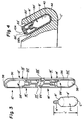
- the adapter 10' shown in Figures 3 and 4 finds utility.
- the recess 30' ( Figure 4) formed by the cooperative association of the indentations 28' in the mated adapter segments 12', 14' is configured to correspond to the size and shape of the tube T' over the entire axial length L' thereof.
- the segments 12', 14' are each provided with an axial extension 36 having a bottom wall 38.
- the bottom wall 38 need not completely close the bottom of the adapter 12', 14, , as is illustrated, but may only partly close the same.
- the presence of the extension 36 and the bottom wall 38 permit the recess 30' defined when the segments 12', 14' are joined to receive the entire axial length L' of the tube T'.
- Figure 4 illustrates this embodiment of the invention in use.
- the closed end C' of the tube T' is contacted by the interior surface of the bottom wall 38.
- the indentations 28' in the segments 12', 14' are placed such that the tube T' lies as close to the bottom of the rotor cavity 40, thereby to maximize the centrifugal force imposed on the liquid sample.
- the feature 34 present in the embodiment of Figure 1 is not required, since the requisite lifting force transmission surface is defined by the bottom wall 38 operating against the bottom end C' of the tube T'.
- the collar 24 may be eliminated.
- Figure 5 illustrates a modification of the embodiment of the invention shown in Figure 3.
- the tube T'' has the form of a test tube, with no constriction present to define a neck N.
- the segments 12'', 14'' are modified to exhibit indentations 28'' similar to those shown in Figure 3, but which correspond in size and shape to the test tube T'' over the entire axial length L'' thereof.
- the hinge between the segments is disposed on the upper surface portion of the exterior surface of the adapter segments. Such a disposition is believed advantageous in that it locates the hinge at a position where the hinge does not interfere with the receipt of the adapter within the rotor cavity. At the same time the hinge defines a useful lifting appliance.
- the adapter previously illustrated and discussed may find utility in the environment of a vertical angle rotor, such a utilization may typically require the provision of a suitable capping arrangement to prevent tube failure.
- the capping arrangement is required in the case that the adapter does not completely surround the tube, such as shown in Figures 1 and 2.
- a capping arrangement is also required if the adapter does completely surround the tube, as shown in Figures 3 through 6, but does not have sufficient strength to withstand the vertical force due to liquid pressure under centrifugation.
- capping arrangement may be viewed as disadvantageous for various reasons. Accordingly, it is believed desirable to provide an adapter able to support a closed tube T in a vertical angle rotor without the necessity of a capping mechanism.
- Figure 7 illustrates such an adapter in accordance with another embodiment of the present invention.
- the vertical angle rotor adapter shown in Figure 7 is generally indicated by the reference character 10 3 and is generally similar to the adapters 10' and 10'' discussed in connection with Figures 3 and 5 in the sense that the adapter 10 3 is arranged to totally surround the tube T disposed therewithin.
- the adapter 10 3 comprises a first adapter segment 12 3 and a second adapter segment 14 3 .
- Each segment 12 3 , 14 3 has an exterior surface 16 3 thereon.
- the exterior surface 16 3 of each segment 12 3 , 14 3 is defined by a generally cylindrical lateral surface portion 20 3 and a planar upper surface portion 22 3 .
- the adapter segment 12 3 has a planar mating surface 18 3 thereon while the adapter segment 14 3 has a planar mating surface 19 3 thereon.
- the mating surfaces 18 3 and 19 3 on the segments 12 3 and 14 3 are angled with respect to a predetermined reference plane, to be defined.
- the inclination of the mating surfaces 18 3 and 19 3 on the segments 12 3 and 14 3 , respectively, is believed best seen in Figures 9A and 9B. It should be understood that the mating surfaces of the adapter segments in any of the embodiments shown in Figures 1 through 6 may also be inclined in the manner shown in Figures 9A and 9B.
- each of the adapter segments 12 3 and 14 3 each have an indentation 28 3 therein.
- the indentation 28 3 in each segment 12 3 and 14 3 corresponds to the size and contour of the entire axial length L of the tube T.
- the indentations 28 3 therein cooperate to define a recess 30 3 ( Figure 8) that corresponds to the size and shape of the entire axial length of the tube T ( Figures 1 and 8) that is received therein.
- the indentations 28 3 in each segment are shaped such that when the segments 12 3 and 14 3 are joined along their respective mating surfaces 18 3 and 19 3 the indentations 28 3 in each segment cooperate to define a recess 30 3 able to totally surround a centrifuge tube T disposed therein.
- Figure 8 illustrates the adapter 10 3 in accordance with this aspect of the present invention in use in the environment of a vertical angle centrifuge rotor 42 V .
- the axis of each cavity 40 V is parallel or approaching parallel (with an inclination angle of not more than fifteen (15) degrees) to the axis of rotation A of the rotor.
- the adapter 10 3 has a central axis 10 3 A that in use, aligns with the axis of the cavity 40 V in which it is disposed and with the axis of rotation A of the vertical angle rotor 42 V .
- the segments 12 3 , 14 3 are connected and supported for relative pivotal movement with respect to each other by at least one hinge 26 3 .
- the pivotal axis 26 3 A ( Figure 8) of the hinge 26 3 that is, the axis about which occurs the relative pivotal motion of the segments 12 3 , 14 3 , extends perpendicular to the axis 10 3 A of the adapter 10 3 .
- the hinge 26 3 may take the form of a live hinge bridging the upper surface portions 22 3 of the segments 12 3 , 14 3 , or may, if desired, take the form of a coined hinge.
- the segments 12 3 , 14 3 may also be joined by moving each segment toward the other along the line of action 48.
- the line of action 48 also lies in the plane perpendicular to the pivotal axis 26 3 A of the hinge 26 3 .
- any variations in the size of the various cavities 40 V in a given rotor, variations in cavity size from rotor to rotor, and variations in the thickness of the segments from adapter to adapter may be accommodated without breaking the total containment of the tube T by the adapter.
- the radial distance R 3 as the distance between the central axis 10 3 and the exterior surface of the adapter segment 14 3 in the region of the indentation 28 3 therein and the radial distance R 2 as the distance between the central axis 10 3 and the exterior surface of the adapter segment 12 3 in the region of the indentation 28 3 therein.
- the thickness of the segment 12 3 is equal to the difference between the distances R 4 and R 2
- thickness of the segment 14 3 is equal to the difference between the distances R 3 and R 1 .
- the arc length of the inner surface of the segment 14 3 i.e., the distance between the points 50-50 in a plane perpendicular to the adapter axis 10 3 A (the plane of Figure 9A) plus the arc length of the inner surface of the segment 12 3 (i.e., the distance between the points 52-52) in the same plane must equal the circumference of the inside of the adapter in a plane perpendicular to the adapter axis 10 3 A in the case when the adapter of the smallest segment thickness is conformed to the largest rotor cavity, as illustrated in Figure 9B.
- the magnitude of angles of inclination of the surfaces may be measured by reference to a reference plane 54.
- the reference plane 54 is that plane that contains both the vertical central axis 10 3 of the adapter 10 3 and at least one of the inwardly projecting corners 50 of the adapter segment 14 3 .
- the reference plane 54 may be defined as the plane that is normal to the line of action 48 (superimposed on Figure 9A) along which the segments 12 3 , 14 3 are joined together.
- the inclination of the surfaces 18 3 and 19 3 lies in the range of angles from about 10 to about 80 degrees.
- each angle is forty five (45) degrees.
- the surfaces 18 3 and 19 3 are shown as being inclined to the same degree (i.e., the angles of the surfaces 18 3 and 19 3 with respect to the reference plane 54 are equal), such is not necessarily required. It is only necessary that the inclination of the surfaces 18 3 and 19 3 be such that the segments are maintained in mutual contact if they expand during centrifugation to fill the cavity 40 V . It should also be noted that the segments 12 3 and 14 3 may be other than circular, and can be ellipsoidal, if desired.
- An adapter in accordance with this embodiment of the present invention may be fabricated from any suitable material so long as the resulting adapter has sufficient strength (as that term is defined herein).
- the material of choice must exhibit other desirable properties, such as appropriate ultimate strength, appropriate modulus of elasticity, suitable chemical compatibility with any liquid sample being centrifuged and ability to withstand autoclaving.
- Suitable plastic materials include polypropylene, polyamide, acetal, polyphenylene oxide, polyvinyl choloride, polycarbonate or polyethylene.
- Other plastic or metallic materials either homogeneous (neat) or fiber reinforced) with similar or better mechanical and chemical properties for the application under consideration may also be used.
- the adapter may be formed in any convenient manner consistent with the material selected, such as molding, machining, casting or forging.
- the adapter 10 3 In order to support a tube T in a vertical angle rotor without the assistance of the restraining force provided by a capping mechanism, the adapter 10 3 must exhibit sufficient strength to absorb the forces imposed on the tube T by the pressure of the liquid therein. Thus, as the term is used herein,” sufficient strength means that the adapter must be able to withstand the forces imposed on it during centrifugation without failing or deforming to the extent that the tube carried therein ruptures.
- Whether a given adapter sufficient strength, and thus falls within the scope of the claims of the present invention, can be determined from various readily ascertainable operating parameters of the vertical angle rotor in which the adapter is to be used and the application to which the adapter is to be put. These parameters are the specific weight of the liquid sample within the tube received by adapter, the radius R i which represents the minimum distance to the sample from the axis A of rotation ( Figure 8), the diameter D o ( Figure 8) of the rotor cavity, the thickness of the adapter segment, the inside diameter of the tube, and the speed of rotation of the vertical angle rotor.
- the total vertical force F that the adapter must withstand is then found by integrating this pressure function over the circular cross sectional area of the inside of the tube.
- the modulus of elasticity of that material may be readily obtained.
- An estimation of the vertical deformation of the adapter may be found by multiplying the initial length of the adapter by the average stress divided by the modulus of modulus of elasticity of the adapter material. If the average stress calculated in Equation (2) is less than the ultimate strength of the adapter material, and the predicted deformation is less that the deformation that will cause first leakage in the tube carried within the adapter, then the given adapter is to be construed to have sufficient strength for at least one operating cycle, and therefore fall within the contemplation of the present invention. The determination of sufficient strength as set forth above under operating conditions will verify both the analysis and the conclusion of the sufficiency of strength of the adapter.
Landscapes
- Centrifugal Separators (AREA)
Priority Applications (1)
| Application Number | Priority Date | Filing Date | Title |
|---|---|---|---|
| EP96102779A EP0718039A2 (en) | 1989-11-07 | 1990-11-07 | Centrifuge tube adapter |
Applications Claiming Priority (5)
| Application Number | Priority Date | Filing Date | Title |
|---|---|---|---|
| US43264689A | 1989-11-07 | 1989-11-07 | |
| US432646 | 1989-11-07 | ||
| US55263190A | 1990-07-13 | 1990-07-13 | |
| PCT/US1990/006326 WO1991006373A1 (en) | 1989-11-07 | 1990-11-07 | Hinged centrifuge tube adapter |
| US552631 | 2000-04-19 |
Related Child Applications (1)
| Application Number | Title | Priority Date | Filing Date |
|---|---|---|---|
| EP96102779.4 Division-Into | 1990-11-07 |
Publications (3)
| Publication Number | Publication Date |
|---|---|
| EP0500768A1 EP0500768A1 (en) | 1992-09-02 |
| EP0500768A4 EP0500768A4 (en) | 1992-10-07 |
| EP0500768B1 true EP0500768B1 (en) | 1996-09-11 |
Family
ID=27029583
Family Applications (2)
| Application Number | Title | Priority Date | Filing Date |
|---|---|---|---|
| EP96102779A Withdrawn EP0718039A2 (en) | 1989-11-07 | 1990-11-07 | Centrifuge tube adapter |
| EP91900113A Expired - Lifetime EP0500768B1 (en) | 1989-11-07 | 1990-11-07 | Hinged centrifuge tube adapter |
Family Applications Before (1)
| Application Number | Title | Priority Date | Filing Date |
|---|---|---|---|
| EP96102779A Withdrawn EP0718039A2 (en) | 1989-11-07 | 1990-11-07 | Centrifuge tube adapter |
Country Status (6)
| Country | Link |
|---|---|
| EP (2) | EP0718039A2 (ja) |
| JP (1) | JPH0763655B2 (ja) |
| CA (1) | CA2068205A1 (ja) |
| DE (1) | DE69028549T2 (ja) |
| IE (1) | IE903997A1 (ja) |
| WO (1) | WO1991006373A1 (ja) |
Families Citing this family (9)
| Publication number | Priority date | Publication date | Assignee | Title |
|---|---|---|---|---|
| US5935052A (en) * | 1993-05-27 | 1999-08-10 | Sorvall Products, L.P. | Adapter for centrifuge tube |
| US5422018A (en) * | 1994-01-31 | 1995-06-06 | Applied Imaging | Centrifuge tube and adaptor |
| US5901873A (en) * | 1997-04-25 | 1999-05-11 | Beckman Instruments, Inc. | Self-seating self-sealing labware adapter |
| US6254834B1 (en) * | 1998-03-10 | 2001-07-03 | Large Scale Proteomics Corp. | Detection and characterization of microorganisms |
| JP5105925B2 (ja) | 2007-03-26 | 2012-12-26 | 京セラメディカル株式会社 | 遠心分離用デバイス |
| EP2190581B1 (en) | 2007-08-21 | 2012-12-05 | Nalge Nunc International Corporation | Centrifuge bottle closure and assembly thereof |
| JP5333759B2 (ja) * | 2009-06-30 | 2013-11-06 | 日立工機株式会社 | 遠心分離機 |
| EP2269740B1 (en) | 2009-06-30 | 2015-11-04 | Hitachi Koki CO., LTD. | Centrifugal separator |
| AT517083B1 (de) | 2015-05-04 | 2016-11-15 | Greiner Bio-One Gmbh | Abnahmebaugruppe, insbesondere für eine geringere Aufnahmemenge |
Family Cites Families (8)
| Publication number | Priority date | Publication date | Assignee | Title |
|---|---|---|---|---|
| US3159298A (en) * | 1962-08-08 | 1964-12-01 | Saw Harold | Combined sealing cap and drinking vessel |
| US3674197A (en) * | 1970-09-08 | 1972-07-04 | Sorvall Inc Ivan | Washing means for flexible bags in split enclosures |
| US4015775A (en) * | 1975-07-16 | 1977-04-05 | E. I. Du Pont De Nemours And Company | Method of gradient separation |
| US4290550A (en) * | 1980-02-19 | 1981-09-22 | Beckman Instruments, Inc. | Modular supporting cap and spacer for centrifuge tubes |
| US4304356A (en) * | 1980-02-19 | 1981-12-08 | Beckman Instruments, Inc. | Supporting cap for sealed centrifuge tube |
| US4451250A (en) * | 1982-09-27 | 1984-05-29 | E. I. Du Pont De Nemours And Company | Inside adapter for a sample container |
| US4552278A (en) * | 1984-10-30 | 1985-11-12 | E. I. Du Pont De Nemours And Company | Crimpable capping assembly for a centrifuge tube |
| US4692137A (en) * | 1985-04-03 | 1987-09-08 | Beckman Instruments, Inc. | Split tube centrifuge rotor adapter |
-
1990
- 1990-11-06 IE IE399790A patent/IE903997A1/en not_active Application Discontinuation
- 1990-11-07 JP JP3500793A patent/JPH0763655B2/ja not_active Expired - Lifetime
- 1990-11-07 EP EP96102779A patent/EP0718039A2/en not_active Withdrawn
- 1990-11-07 EP EP91900113A patent/EP0500768B1/en not_active Expired - Lifetime
- 1990-11-07 DE DE69028549T patent/DE69028549T2/de not_active Expired - Fee Related
- 1990-11-07 CA CA 2068205 patent/CA2068205A1/en not_active Abandoned
- 1990-11-07 WO PCT/US1990/006326 patent/WO1991006373A1/en active IP Right Grant
Also Published As
| Publication number | Publication date |
|---|---|
| IE903997A1 (en) | 1991-05-08 |
| WO1991006373A1 (en) | 1991-05-16 |
| EP0500768A4 (en) | 1992-10-07 |
| CA2068205A1 (en) | 1991-05-08 |
| EP0500768A1 (en) | 1992-09-02 |
| JPH0763655B2 (ja) | 1995-07-12 |
| EP0718039A2 (en) | 1996-06-26 |
| EP0718039A3 (ja) | 1996-07-31 |
| DE69028549D1 (de) | 1996-10-17 |
| JPH05501673A (ja) | 1993-04-02 |
| DE69028549T2 (de) | 1997-04-17 |
Similar Documents
| Publication | Publication Date | Title |
|---|---|---|
| EP0500768B1 (en) | Hinged centrifuge tube adapter | |
| EP1246701B1 (en) | A container assembly having a support bridge | |
| US4451250A (en) | Inside adapter for a sample container | |
| US5399144A (en) | Centrifuge tube adapter | |
| US5382220A (en) | Centrifuge tube adapter | |
| US4990129A (en) | Swinging bucket ultracentrifuge rotor, sample tube and adapter | |
| WO1992019382A1 (en) | Centrifuge tube adapter | |
| EP0609381B1 (en) | Cartridge adapter having a secondary seal | |
| EP0642389B1 (en) | Centrifuge | |
| EP0626207B1 (en) | Adapter for holding a pair of centrifuge tubes | |
| EP0368173A2 (en) | Cavity sealing system for a centrifuge rotor | |
| JP3516023B2 (ja) | 遠心機のスナッププラグ付きチューブ | |
| EP0626206A2 (en) | Adapter for centrifuge tube | |
| US5291783A (en) | Tube for use in a fixed angle centrifuge rotor | |
| IE903996A1 (en) | Hinged centrifuge tube adapter | |
| JPH11318870A (ja) | 採血管及びそれを利用した血清や血漿の分離方法 | |
| EP0578779A4 (en) | LOCKING ARRANGEMENT THAT ALLOWS THE USE OF Hermetically CLOSED TUBES IN A PIVOT SENSOR CENTRIFUGE. | |
| EP0035829A1 (en) | Supporting cap and spacer for centrifuge tubes |
Legal Events
| Date | Code | Title | Description |
|---|---|---|---|
| PUAI | Public reference made under article 153(3) epc to a published international application that has entered the european phase |
Free format text: ORIGINAL CODE: 0009012 |
|
| 17P | Request for examination filed |
Effective date: 19920429 |
|
| AK | Designated contracting states |
Kind code of ref document: A1 Designated state(s): DE GB |
|
| A4 | Supplementary search report drawn up and despatched |
Effective date: 19920820 |
|
| AK | Designated contracting states |
Kind code of ref document: A4 Designated state(s): DE GB |
|
| 17Q | First examination report despatched |
Effective date: 19931103 |
|
| GRAH | Despatch of communication of intention to grant a patent |
Free format text: ORIGINAL CODE: EPIDOS IGRA |
|
| GRAH | Despatch of communication of intention to grant a patent |
Free format text: ORIGINAL CODE: EPIDOS IGRA |
|
| GRAA | (expected) grant |
Free format text: ORIGINAL CODE: 0009210 |
|
| AK | Designated contracting states |
Kind code of ref document: B1 Designated state(s): DE GB |
|
| XX | Miscellaneous (additional remarks) |
Free format text: TEILANMELDUNG 96102779.4 EINGEREICHT AM 24/02/96. |
|
| REF | Corresponds to: |
Ref document number: 69028549 Country of ref document: DE Date of ref document: 19961017 |
|
| PGFP | Annual fee paid to national office [announced via postgrant information from national office to epo] |
Ref country code: GB Payment date: 19961205 Year of fee payment: 7 |
|
| PLBE | No opposition filed within time limit |
Free format text: ORIGINAL CODE: 0009261 |
|
| STAA | Information on the status of an ep patent application or granted ep patent |
Free format text: STATUS: NO OPPOSITION FILED WITHIN TIME LIMIT |
|
| 26N | No opposition filed | ||
| PG25 | Lapsed in a contracting state [announced via postgrant information from national office to epo] |
Ref country code: GB Free format text: LAPSE BECAUSE OF NON-PAYMENT OF DUE FEES Effective date: 19971107 |
|
| GBPC | Gb: european patent ceased through non-payment of renewal fee |
Effective date: 19971107 |
|
| PGFP | Annual fee paid to national office [announced via postgrant information from national office to epo] |
Ref country code: DE Payment date: 20081223 Year of fee payment: 19 |
|
| PG25 | Lapsed in a contracting state [announced via postgrant information from national office to epo] |
Ref country code: DE Free format text: LAPSE BECAUSE OF NON-PAYMENT OF DUE FEES Effective date: 20100601 |