EP0500748B1 - Kompaktes kontaktkopiergerät mit transparenter, flexibler abdeckung - Google Patents
Kompaktes kontaktkopiergerät mit transparenter, flexibler abdeckung Download PDFInfo
- Publication number
- EP0500748B1 EP0500748B1 EP19900917615 EP90917615A EP0500748B1 EP 0500748 B1 EP0500748 B1 EP 0500748B1 EP 19900917615 EP19900917615 EP 19900917615 EP 90917615 A EP90917615 A EP 90917615A EP 0500748 B1 EP0500748 B1 EP 0500748B1
- Authority
- EP
- European Patent Office
- Prior art keywords
- cover sheet
- film
- original
- light
- sheet member
- Prior art date
- Legal status (The legal status is an assumption and is not a legal conclusion. Google has not performed a legal analysis and makes no representation as to the accuracy of the status listed.)
- Expired - Lifetime
Links
- 239000000463 material Substances 0.000 claims description 9
- 230000003287 optical effect Effects 0.000 claims description 6
- 239000000428 dust Substances 0.000 claims description 5
- 238000005299 abrasion Methods 0.000 claims description 3
- JOYRKODLDBILNP-UHFFFAOYSA-N Ethyl urethane Chemical compound CCOC(N)=O JOYRKODLDBILNP-UHFFFAOYSA-N 0.000 claims description 2
- 229920006267 polyester film Polymers 0.000 claims 1
- 238000003475 lamination Methods 0.000 description 7
- 230000035945 sensitivity Effects 0.000 description 6
- 230000005855 radiation Effects 0.000 description 5
- 230000002411 adverse Effects 0.000 description 4
- 238000000576 coating method Methods 0.000 description 4
- 230000033001 locomotion Effects 0.000 description 4
- 238000000034 method Methods 0.000 description 4
- 230000033458 reproduction Effects 0.000 description 4
- 238000000926 separation method Methods 0.000 description 4
- 239000011248 coating agent Substances 0.000 description 3
- 239000000839 emulsion Substances 0.000 description 3
- 230000001965 increasing effect Effects 0.000 description 3
- 239000007787 solid Substances 0.000 description 3
- OAICVXFJPJFONN-UHFFFAOYSA-N Phosphorus Chemical compound [P] OAICVXFJPJFONN-UHFFFAOYSA-N 0.000 description 2
- 230000005540 biological transmission Effects 0.000 description 2
- 230000006835 compression Effects 0.000 description 2
- 238000007906 compression Methods 0.000 description 2
- 229910001507 metal halide Inorganic materials 0.000 description 2
- 150000005309 metal halides Chemical class 0.000 description 2
- 238000006748 scratching Methods 0.000 description 2
- 230000002393 scratching effect Effects 0.000 description 2
- -1 silver halide Chemical class 0.000 description 2
- 230000003068 static effect Effects 0.000 description 2
- 206010034960 Photophobia Diseases 0.000 description 1
- 238000009825 accumulation Methods 0.000 description 1
- 238000002508 contact lithography Methods 0.000 description 1
- 230000000694 effects Effects 0.000 description 1
- 230000002708 enhancing effect Effects 0.000 description 1
- 239000004744 fabric Substances 0.000 description 1
- 239000011521 glass Substances 0.000 description 1
- 238000005286 illumination Methods 0.000 description 1
- 208000013469 light sensitivity Diseases 0.000 description 1
- 230000000670 limiting effect Effects 0.000 description 1
- 238000004519 manufacturing process Methods 0.000 description 1
- 229920000728 polyester Polymers 0.000 description 1
- 230000002829 reductive effect Effects 0.000 description 1
- 230000002441 reversible effect Effects 0.000 description 1
- 229910052709 silver Inorganic materials 0.000 description 1
- 239000004332 silver Substances 0.000 description 1
- 238000003892 spreading Methods 0.000 description 1
- 238000003860 storage Methods 0.000 description 1
- 238000011282 treatment Methods 0.000 description 1
- WFKWXMTUELFFGS-UHFFFAOYSA-N tungsten Chemical compound [W] WFKWXMTUELFFGS-UHFFFAOYSA-N 0.000 description 1
- 229910052721 tungsten Inorganic materials 0.000 description 1
- 239000010937 tungsten Substances 0.000 description 1
- XLYOFNOQVPJJNP-UHFFFAOYSA-N water Substances O XLYOFNOQVPJJNP-UHFFFAOYSA-N 0.000 description 1
- 238000004804 winding Methods 0.000 description 1
Images

Classifications
-
- G—PHYSICS
- G03—PHOTOGRAPHY; CINEMATOGRAPHY; ANALOGOUS TECHNIQUES USING WAVES OTHER THAN OPTICAL WAVES; ELECTROGRAPHY; HOLOGRAPHY
- G03B—APPARATUS OR ARRANGEMENTS FOR TAKING PHOTOGRAPHS OR FOR PROJECTING OR VIEWING THEM; APPARATUS OR ARRANGEMENTS EMPLOYING ANALOGOUS TECHNIQUES USING WAVES OTHER THAN OPTICAL WAVES; ACCESSORIES THEREFOR
- G03B27/00—Photographic printing apparatus
- G03B27/02—Exposure apparatus for contact printing
- G03B27/14—Details
- G03B27/16—Illumination arrangements, e.g. positioning of lamps, positioning of reflectors
-
- G—PHYSICS
- G03—PHOTOGRAPHY; CINEMATOGRAPHY; ANALOGOUS TECHNIQUES USING WAVES OTHER THAN OPTICAL WAVES; ELECTROGRAPHY; HOLOGRAPHY
- G03B—APPARATUS OR ARRANGEMENTS FOR TAKING PHOTOGRAPHS OR FOR PROJECTING OR VIEWING THEM; APPARATUS OR ARRANGEMENTS EMPLOYING ANALOGOUS TECHNIQUES USING WAVES OTHER THAN OPTICAL WAVES; ACCESSORIES THEREFOR
- G03B27/00—Photographic printing apparatus
- G03B27/02—Exposure apparatus for contact printing
- G03B27/10—Copying apparatus with a relative movement between the original and the light source during exposure
-
- G—PHYSICS
- G03—PHOTOGRAPHY; CINEMATOGRAPHY; ANALOGOUS TECHNIQUES USING WAVES OTHER THAN OPTICAL WAVES; ELECTROGRAPHY; HOLOGRAPHY
- G03B—APPARATUS OR ARRANGEMENTS FOR TAKING PHOTOGRAPHS OR FOR PROJECTING OR VIEWING THEM; APPARATUS OR ARRANGEMENTS EMPLOYING ANALOGOUS TECHNIQUES USING WAVES OTHER THAN OPTICAL WAVES; ACCESSORIES THEREFOR
- G03B27/00—Photographic printing apparatus
- G03B27/02—Exposure apparatus for contact printing
- G03B27/14—Details
- G03B27/18—Maintaining or producing contact pressure between original and light-sensitive material
- G03B27/20—Maintaining or producing contact pressure between original and light-sensitive material by using a vacuum or fluid pressure
Definitions
- Contact printing or exposure is a traditional graphic arts procedure for generating same size, high resolution reproductions of line and halftone film images.
- This technique ensures faithful original film image reproduction by placing the original film image in intimate contact with a receiving film or paper emulsion and, in the presence of a vacuum to hold them in intimate contact throughout the exposing process, exposing through the original film image to the receiving film or paper by means of a point or reflected light source.
- these images are of a relatively large size in order to meet the needs of the graphic arts industry and thus require large format originals and receiving films and the equipment necessary to handle such sized films.
- British Patent No. 1,116,151 discloses a contact printer utilizing a vacuum frame on which an original and a light-sensitive film are superposed for exposure by a light source carried in a movable head. A transparent cover sheet is applied over the superposed film and original prior to exposure by means of a draw-bar driven by endless chains along the edges of the vacuum frame.
- the present invention provides an improvement in a contact printer comprising means (14) for supporting a film (18) and an original (20) in superposed relationship, a source of light (32) for exposing the film through the original, light carriage means (16) for moving the light source in spaced relationship with the surface of the superposed film and original whereby the film is exposed through the original, a cover sheet member (36) which is substantially flexible, impervious to air, and transparent to the light of the light source, to cover the superposed film and original, and means (52, 54, 56, 58) or supporting a roll (48) of the coversheet member (36).
- the improvement is characterized in that the supporting means (52, 54, 56, 58) are disposed on the light carriage means (16) for covering the superposed film and original with the cover sheet member (36) as the light carriage means (16) is moved across the film and original whereby the cover sheet member is unwound from the roll (48) and applied simultaneously as the film is exposed by the light source through the cover sheet member and the original, and in that the light carriage means comprises pressure means (38) which force the cover sheet, film and original in intimate contact with one another.
- the improvement comprises means for contacting the surface of the cover sheet during use and removing dust and dirt thereon to assure that the optical path for the exposing light remains clear and unobstructed.
- the improvement comprises means for removing and replacing the cover sheet to assure that the optical path for the exposing light remains clear and unobstructed.
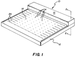
- the contact printer comprises a platen member 12 having a planar upper surface 14 with dimensions slightly larger than the maximum dimensions of the largest original to be copied thereon.
- a light carriage 16 having a length approximately equal to one dimension of the platen member 12, is arranged to be moved across the platen transversely to the length of the carriage, thereby providing coverage of the entire platen during its movement.
- the upper surface of the platen member 14 forms a vacuum table for the film 18 and the original 20 which are superposed thereon for exposure of the film (see Fig. 2).
- a plurality of vacuum ports 24 are formed in the film/original accepting portion of the surface 14 and communicate between the surface and the interior of the chamber. With the exception of the vacuum ports 24, the chamber 22 is sealed so that a vacuum pump (not shown, but normally disposed remote from the apparatus) can pull a vacuum within the chamber which is then applied, via ports 24, to the film and original which are placed on the surface 14.
- the ports 24 have a diameter of approximately 0.040 inch [1.0 mm] which is sufficiently large to effectively apply the vacuum to the film/original disposed on the surface 14, but is sufficiently small and the capacity of the vacuum pump is great enough that it will maintain the vacuum even though the size of the film/original is less than the maximum, leaving some of the vacuum ports uncovered.
- the vacuum ports outside of the area covered by the maximum size film/original are connected by shallow grooves 26 having a cross section of 0.015 inch by 0.015 inch [0.4 mm x 0.4 mm] which permit air trapped between the film/original and a cover sheet (to be further described hereinbelow) to be evacuated.
- the light carriage 16 is disposed on the upper surface of the vacuum table and is arranged to be moved across the table from a home position (the rear of the vacuum table in the example illustrated) to the opposite edge of the table, and returned to the home position.
- the carriage is provided with wheels (not shown) at each end thereof which ride upon tracks (not shown) provided at the lateral edges of the platen surface 14 or within the platen.
- the carriage is driven by a drive screw 28 within and extending the length of the platen which engages and drives a drive-nut 30 connected to the carriage.
- the drive screw is driven by a variable speed, reversible motor (not shown) located within the platen 12.
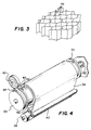
- the light carriage 16 carries one or more high UV output fluorescent aperture lamps 32, with an associated mechanical light collimator 34 positioned beneath each lamp, a roll of a transparent cover sheet 36, an associated pressure roller 38, and a pair of cleaner rolls 40 and 42.
- the fluorescent lamps 32 are long tubular bulbs extending the length of the carriage.
- the phosphors which coat the inner walls of the bulbs are selected to generate light having a wavelength in the range of 350nm to 460nm, which matches the sensitivity of the film being exposed.
- the bulbs have an internal reflective layer between the phosphor and the envelope glass which covers a major angular portion of the envelope wall and reflects a high percentage of the radiation striking it.
- a clear window 44 having an aperture of about 60° of the bulb circumference, is provided along the length of the bulb with no phosphor or reflective layer. This window produces an elongated, concentrated beam of high luminance UV light output along the length of the bulb because the reflective coating directs the major part of the bulb output through the uncoated window.
- the lamps are selectively oriented in the carriage with the windows 44 directed downwardly so that the beam of concentrated light is directed toward the sensitized film material 18.
- the mechanical light collimator 34 associated with each bulb comprises a plurality of parallel, fine collimator tubes 46 (Fig. 3) which are closely spaced and which transmit parallel rays of light from the fluorescent aperture lamp to the exposure plane. While the optimum tube shape for the light collimator is a cylinder, because it gives uniform image quality in all directions, it has been found that tubes having a hexagonal cross section provide close approximation to the cylinder, are easier to fabricate, and provide greater useful area for light transmission as a light collimator.
- the inner surface of the tubes are provided with a non-reflective black coating whereby light rays which are not parallel to the tube axes are absorbed.
- the equivalent diameter of the tubes and their length are selected to extinguish incident angles of light at the exposure plane greater than a predetermined solid angle, for example a solid angle of between about 3° and about 9°.
- a predetermined solid angle for example a solid angle of between about 3° and about 9°.
- the illumination at the film surface depends upon the light output of the lamp and the distance of the lamp from the film surface, for a given lamp output, the shorter the length of the collimator, the greater the exposure power at the film.
- a preferred embodiment employs hexagonal tubes having an equivalent diameter of 0.125 inch [3.2 mm] and a length of 0.5 inch [12.8 mm], with the bottom of the tube spaced above the film plane a distance of 0.5 inch [12.8 mm].
- the transparent cover sheet 36 has dimensions substantially equal to the width and length of the vacuum table and is supported as a roll 48 mounted in the carriage 16 parallel with and ahead of the fluorescent tubes (as viewed with respect to the initial travel of the carriage).
- the outer, free end of the cover sheet is releaseably connected to the vacuum table as indicated at 50.
- the cover sheet is wrapped on a core 52 which is removably held at each end by hub members, 54 and 56, rotatably mounted in the carrier.
- One hub 54 is connected to one end of a constant force tension spring 58 which acts to apply tension to the roll of the cover sheet material as it is unwound and wound by movement of the carriage across the vacuum table, as will be further described hereinbelow.
- the other end of the tension spring is connected to and wrapped on a storage drum 60 where it remains in its idle position.
- the spring is transferred onto the core hub 54, and produces the winding torque moment to the shaft of the core to rewind the cover sheet when the carriage movement is reversed.
- the other hub 56 is spring loaded along the core axis by an axial compression spring 62.
- the axial compression spring permits the hub 56 to be moved axially, disengaging the cover sheet roll to permit its easy replacement.
- the cover sheet 36 is formed of an impermeable sheet of a polymeric material which is substantially transparent to UV radiation.
- the material also preferably resists abrasion and possesses anti-static properties, or is treated to obtain these properties, so that it resists the accumulation of dust, dirt, and other materials which would adversely affect the transmission of exposing light therethrough, or which would adversely affect the collimation of the light. It has been found that a sheet of clear polyester sheeting having a thickness of approximately 0.004 inch [0.1 mm] satisfactorily meets these requirements.
- the sheeting may be provided with anti-static properties via coatings or other treatments to minimize the static attraction of dust and dirt to the cover sheet, to prevent the cover sheet from "clinging" to the film/original laminate, and to prevent static discharges which can impart an unwanted exposure to the film.
- the sheeting can also be provided with an abrasion resistant coating to minimize scratching of the cover sheet which would adversely affect its "clear" optical properties.
- the cover sheet can be provided, on the surface thereof which contacts the film/original laminate, with an optically clear matte finish which facilitates the ready application of the vacuum to the cover sheet/original/film laminate by providing miniscule air passages for the removal of air.
- the cover sheet acts as a "vacuum lid” as it is unwound over the original/film laminate during vacuum drawdown as the carriage is moved across the vacuum table to expose the film.
- the cover sheet also protects the original/film laminate underneath from any abrasive action of the pressure roller 38 as it forces the cover sheet/original/film lamination into intimate contact to remove any air from the lamination which might otherwise distort the resulting exposure.
- the cover sheet can be cleaned with a soft cloth if necessary, or be replaced if it loses its transparency or becomes damaged.
- the cleaner rolls 40 and 42 are mounted transversely of the light carriage 16 between the cover sheet roll 48 and the pressure roller 38 in engagement with the front and rear surfaces of the cover sheet 36.
- the cleaner rolls are formed of a single component urethane having 20 durometer Shore A hardness which clean the cover sheet without scratching as it is extended and retracted during each exposure cycle.
- cooperating clearance holes can be provided in the cover sheet 36.
- the clearance holes allow the cover sheet to lie flat around the registration pins as it is unwound over the original/film laminate.
- the light carriage 16 is parked at the rear of the vacuum table 14.
- a sheet of film or paper 18 is positioned emulsion side-up on the platen.
- the longest sheet dimension is preferably perpendicular to carriage motion to minimize the carriage travel necessary to fully cover the sheet and thus keep the time required to a minimum.
- the vacuum pump is activated and applies the vacuum to the film through the ports 24 to hold the film to the platen surface.
- the original 20, such as a color separation, is then placed on top of the film.
- the separation can be positioned by means of registration pins (not shown). If registration pins are used, they are located along the edge of the original/film laminate closest to the carriage home position.
- the type of film or paper to be exposed, or the exposure speed thereof, is entered into the machine controller.
- the film information and lamp intensity readings are then used to calculate the carriage traverse speed.
- the "start" button is actuated, the carriage moves 16 forward toward the front edge of the platen 14 at the proper dot-for-dot exposure speed. While the carriage moves forward, the clear anti-static cover sheet 36 is unwound to cover the original/film lamination. The pressure roller 38 pushes out any remaining air from the lamination and the cover sheet is drawn into intimate contact with the lamination by the vacuum through the ports 24. The carriage continues until the "end of travel” position is reached and reverses direction to finish exposing the film and return to the home position.
- the cover sheet 36 is rewound on the core 52 by the constant tension spring 58, uncovering the original/film lamination after exposure for that area has been completed. It is apparent that, with small film sizes, complete traverse of the platen by the carriage is not necessary.
- the "end of travel" position is selectable and can be specified by the user. When the carriage is back at home position, the vacuum and the lamps are shut off or placed on standby, and the film and separation can be removed.
- the preferred embodiment of the present invention has been illustrated as configured to rest on a table top or workbench. It will be apparent that it would be possible to construct the present invention as a stand alone device. The platen could be folded up or down when not in use. Alternatively, the present invention could be wall mounted. The wall mount version could be used where space is at a premium or in multi-functional work areas.
- the present invention can be configured so that the light carriage moves from side to side rather than from back to front.
- the cover sheet can be formed of a material which is only transparent to UV radiation. Other forms of the cover sheet cleaner rolls may also be employed.
- the present invention provides a contact printer which simultaneously exposes sensitized material and draws a vacuum between the original and the film.
- the printer employs a short optical light path, made possible by the mechanical light collimator, which is both compact and inexpensive, and which produces substantially parallel light rays in a short distance.
- the volume of space occupied by the contact printer of the present invention is substantially reduced from that required by contact printers of the prior art, without increasing the risk of exposing the operator to UV radiation, and while enhancing the productivity of the apparatus.
Landscapes
- Physics & Mathematics (AREA)
- General Physics & Mathematics (AREA)
- Fluid Mechanics (AREA)
- Exposure And Positioning Against Photoresist Photosensitive Materials (AREA)
Claims (15)
- Kontaktbelichter mit einer Einrichtung (14) zum Auflegen eines mit einer Vorlage (20) übereinanderliegend angeordneten Films (18), einer Lichtquelle (32), die den Film durch die Vorlage hindurch belichtet, und einem Schlitten (16) zum Bewegen der Lichtquelle im Abstand von der Oberfläche des mit der Vorlage übereinanderliegend angeordneten Films derart, daß dieser durch die Vorlage hindurch belichtbar ist,
einer Abdeckfolie (36), mit der der mit der Vorlage übereinanderliegend angeordnete Film abdeckbar ist und die im wesentlichen flexibel, luftundurchlässig und gegenüber dem Licht der Lichtquelle durchlässig ist, und
Mitteln (52, 54, 56, 58) zum Lagern einer Rolle (48), auf der die Abdeckfolie (36) aufgewickelt ist,
dadurch gekennzeichnet, daß die Lagermittel (52, 54, 56, 58) auf dem Schlitten (16) so angeordnet sind, daß beim Bewegen des Schlittens über den Film und die Vorlage hinweg der mit der Vorlage übereinanderliegend angeordnete Film mittels der Abdeckfolie (36) abdeckbar ist, und daß die Abdeckfolie von der Rolle (48) abwickelbar ist und während der von der Lichtquelle her erfolgenden Belichtung des Films durch die Abdeckfolie und die Vorlage hindurch auf der Vorlage aufliegt,
der Schlitten (16) eine Andrückvorrichtung (38) umfaßt, die die Abdeckfolie, den Film und die Vorlage in engem Kontakt miteinander hält. - Kontaktbelichter nach Anspruch 1, dadurch gekennzeichnet, daß die Abdeckfolie (36) im wesentlichen abriebfest ist.
- Kontaktbelichter nach Anspruch 1, dadurch gekennzeichnet, daß die Abdeckfolie (36) eine antistatische Oberfläche aufweist.
- Kontaktbelichter nach Anspruch 1, dadurch gekennzeichnet, daß die mit dem Film und der darüberliegenden Vorlage in Berührung stehende Oberfläche der Abdeckfolie (36) eine im wesentlichen durchsichtige, matte Ausrüstung aufweist.
- Kontaktbelichter nach Anspruch 1, dadurch gekennzeichnet, daß die Abdeckfolie (36) aus einem im wesentlichen durchsichtigen Polyesterfilm hergestellt ist.
- Kontaktbelichter nach Anspruch 1, dadurch gekennzeichnet, daß die Rolle (48) mit der Abdeckfolie derart lösbar an dem Schlitten (16) befestigt ist, daß sie entfernbar und ersetzbar ist und der optische Strahlengang für die Belichtung frei und unbeeinträchtigt bleibt.
- Kontaktbelichter nach Anspruch 6, dadurch gekennzeichnet, daß die Rolle mit der Abdeckfolie (36) auf einem Kern (52) angeordnet ist, der an seinen gegenüberliegenden Enden durch Nabenelemente (54, 56) lösbar gehalten ist.
- Kontaktbelichter nach Anspruch 6, dadurch gekennzeichnet, daß die Abdeckfolie ein freies Ende (50) besitzt, das außerhalb des den Film enthaltenden Bereichs lösbar an der Filmauflageeinrichtung (14) befestigt ist.
- Kontaktbelichter nach Anspruch 7, dadurch gekennzeichnet, daß mindestens eines der Nabenelemente (54, 56) längs einer Achse des Kerns (52) durch eine Feder vorgespannt ist.
- Kontaktbelichter nach Anspruch 9, dadurch gekennzeichnet, daß das andere Nabenelement (54, 56) am Umfang des Kerns (52) durch eine Feder so vorgespannt ist, daß eine die Abdeckfolie aufwickelnde Kraft entsteht.
- Kontaktbelichter nach Anspruch 1, dadurch gekennzeichnet, daß der Schlitten (16) eine Reinigungswalzenanordnung (40, 42) aufweist, die mit den Flächen der Abdeckfolie während deren Verwendung in Berührung steht und diese Flächen von Staub und Schmutz befreit, damit der optische Strahlengang für die Belichtung frei und unbeeinträchtigt bleibt.
- Kontaktbelichter nach Anspruch 11, dadurch gekennzeichnet, daß die Reinigungswalzenanordnung aus zwei Walzen (40, 42) besteht, die jeweils mit einer Fläche der Abdeckfolie (36) in Berührung stehen.
- Kontaktbelichter nach Anspruch 11, dadurch gekennzeichnet, daß die Walzen (40, 42) aus einem polymeren Material bestehen.
- Kontaktbelichter nach Anspruch 13, dadurch gekennzeichnet, daß das polymere Material aus einem Einkomponenten-Urethan besteht.
- Kontaktbelichterr nach Anspruch 11, dadurch gekennzeichnet, daß die Walzen (40, 42) drehbar und von der Abdeckfolie antreibbar sind.
Applications Claiming Priority (6)
| Application Number | Priority Date | Filing Date | Title |
|---|---|---|---|
| US438567 | 1989-11-17 | ||
| US07/440,576 US4942426A (en) | 1989-11-17 | 1989-11-17 | Cover sheet cleaning means for a contact printer |
| US07/438,822 US4962405A (en) | 1989-11-17 | 1989-11-17 | Compact contact printer with a flexible transparent cover sheet |
| US07/438,567 US4952973A (en) | 1989-11-17 | 1989-11-17 | Removable cover sheet roll for a contact printer |
| US440576 | 1989-11-17 | ||
| US438822 | 1989-11-17 |
Publications (2)
| Publication Number | Publication Date |
|---|---|
| EP0500748A1 EP0500748A1 (de) | 1992-09-02 |
| EP0500748B1 true EP0500748B1 (de) | 1994-02-23 |
Family
ID=27411987
Family Applications (1)
| Application Number | Title | Priority Date | Filing Date |
|---|---|---|---|
| EP19900917615 Expired - Lifetime EP0500748B1 (de) | 1989-11-17 | 1990-11-16 | Kompaktes kontaktkopiergerät mit transparenter, flexibler abdeckung |
Country Status (5)
| Country | Link |
|---|---|
| EP (1) | EP0500748B1 (de) |
| JP (1) | JP2846952B2 (de) |
| DE (1) | DE69006856T2 (de) |
| DK (1) | DK0500748T3 (de) |
| WO (1) | WO1991007694A1 (de) |
Family Cites Families (2)
| Publication number | Priority date | Publication date | Assignee | Title |
|---|---|---|---|---|
| GB1116151A (en) * | 1963-09-19 | 1968-06-06 | Lee Smith Photomechanics Ltd | Improvements in photomechanical printing apparatus |
| JPS5229739A (en) * | 1975-09-02 | 1977-03-05 | Dainippon Screen Mfg Co Ltd | Close contact printing device |
-
1990
- 1990-11-16 EP EP19900917615 patent/EP0500748B1/de not_active Expired - Lifetime
- 1990-11-16 JP JP3500592A patent/JP2846952B2/ja not_active Expired - Lifetime
- 1990-11-16 DK DK90917615T patent/DK0500748T3/da active
- 1990-11-16 DE DE69006856T patent/DE69006856T2/de not_active Expired - Fee Related
- 1990-11-16 WO PCT/US1990/006748 patent/WO1991007694A1/en not_active Ceased
Also Published As
| Publication number | Publication date |
|---|---|
| DE69006856D1 (de) | 1994-03-31 |
| JPH05504414A (ja) | 1993-07-08 |
| DE69006856T2 (de) | 1994-09-08 |
| DK0500748T3 (da) | 1994-03-28 |
| JP2846952B2 (ja) | 1999-01-13 |
| WO1991007694A1 (en) | 1991-05-30 |
| EP0500748A1 (de) | 1992-09-02 |
Similar Documents
| Publication | Publication Date | Title |
|---|---|---|
| US4952973A (en) | Removable cover sheet roll for a contact printer | |
| US4942426A (en) | Cover sheet cleaning means for a contact printer | |
| US3680956A (en) | Apparatus for controlling contrast during reproduction of photographic images | |
| US4962405A (en) | Compact contact printer with a flexible transparent cover sheet | |
| EP0500748B1 (de) | Kompaktes kontaktkopiergerät mit transparenter, flexibler abdeckung | |
| US5155525A (en) | Method of exposing sensitized graphic art film and paper | |
| EP0571370B1 (de) | Kontaktkopiergerät und verfahren zur belichtung von sensibilisierten graphischen filmen und papieren | |
| US4949122A (en) | Contact printer for exposing sensitized graphic art film and paper | |
| US3645621A (en) | Camera-projector with vacuum film platen | |
| JPS58189622A (ja) | フイルム貯蔵、移送、露出および処理装置 | |
| US4965621A (en) | Compact light collimator for a scanning contact printer | |
| GB2201252A (en) | Imaging device | |
| US4992826A (en) | Contact exposure apparatus | |
| US4159175A (en) | Method for producing a printing plate | |
| JP2605717B2 (ja) | パトローネ | |
| US3762815A (en) | Camera with rotatable vacuum exposure plate and ben day screen | |
| JPS6242255B2 (de) | ||
| US5721582A (en) | Printer with vacuum shoe and media cut off member therein | |
| EP0722243B1 (de) | Digitaldrucker mit Stützschuh mit darin liegendem Führungselement für verschiebbare Medien | |
| US5751334A (en) | Printer with support shoe and media metering therein | |
| US3565617A (en) | Method of removing unwanted lines from a master negative transparency | |
| JPH0723765U (ja) | 感熱記録材料の巻回用紙管 | |
| JPH08122937A (ja) | 露光装置 | |
| JPH054150U (ja) | 画像形成装置 | |
| JPS62159568A (ja) | 画像読取装置 |
Legal Events
| Date | Code | Title | Description |
|---|---|---|---|
| PUAI | Public reference made under article 153(3) epc to a published international application that has entered the european phase |
Free format text: ORIGINAL CODE: 0009012 |
|
| 17P | Request for examination filed |
Effective date: 19920428 |
|
| AK | Designated contracting states |
Kind code of ref document: A1 Designated state(s): DE DK FR GB IT |
|
| 17Q | First examination report despatched |
Effective date: 19930125 |
|
| GRAA | (expected) grant |
Free format text: ORIGINAL CODE: 0009210 |
|
| ITF | It: translation for a ep patent filed | ||
| AK | Designated contracting states |
Kind code of ref document: B1 Designated state(s): DE DK FR GB IT |
|
| REG | Reference to a national code |
Ref country code: DK Ref legal event code: T3 |
|
| REF | Corresponds to: |
Ref document number: 69006856 Country of ref document: DE Date of ref document: 19940331 |
|
| ET | Fr: translation filed | ||
| PLBE | No opposition filed within time limit |
Free format text: ORIGINAL CODE: 0009261 |
|
| STAA | Information on the status of an ep patent application or granted ep patent |
Free format text: STATUS: NO OPPOSITION FILED WITHIN TIME LIMIT |
|
| 26N | No opposition filed | ||
| PGFP | Annual fee paid to national office [announced via postgrant information from national office to epo] |
Ref country code: DK Payment date: 19970917 Year of fee payment: 8 |
|
| PGFP | Annual fee paid to national office [announced via postgrant information from national office to epo] |
Ref country code: GB Payment date: 19971007 Year of fee payment: 8 |
|
| PGFP | Annual fee paid to national office [announced via postgrant information from national office to epo] |
Ref country code: FR Payment date: 19971106 Year of fee payment: 8 |
|
| PGFP | Annual fee paid to national office [announced via postgrant information from national office to epo] |
Ref country code: DE Payment date: 19971127 Year of fee payment: 8 |
|
| PG25 | Lapsed in a contracting state [announced via postgrant information from national office to epo] |
Ref country code: GB Free format text: LAPSE BECAUSE OF NON-PAYMENT OF DUE FEES Effective date: 19981116 |
|
| PG25 | Lapsed in a contracting state [announced via postgrant information from national office to epo] |
Ref country code: DK Free format text: LAPSE BECAUSE OF NON-PAYMENT OF DUE FEES Effective date: 19981130 |
|
| GBPC | Gb: european patent ceased through non-payment of renewal fee |
Effective date: 19981116 |
|
| PG25 | Lapsed in a contracting state [announced via postgrant information from national office to epo] |
Ref country code: FR Free format text: LAPSE BECAUSE OF NON-PAYMENT OF DUE FEES Effective date: 19990730 |
|
| REG | Reference to a national code |
Ref country code: FR Ref legal event code: ST |
|
| PG25 | Lapsed in a contracting state [announced via postgrant information from national office to epo] |
Ref country code: DE Free format text: LAPSE BECAUSE OF NON-PAYMENT OF DUE FEES Effective date: 19990901 |
|
| REG | Reference to a national code |
Ref country code: DK Ref legal event code: EBP |
|
| PG25 | Lapsed in a contracting state [announced via postgrant information from national office to epo] |
Ref country code: IT Free format text: LAPSE BECAUSE OF NON-PAYMENT OF DUE FEES;WARNING: LAPSES OF ITALIAN PATENTS WITH EFFECTIVE DATE BEFORE 2007 MAY HAVE OCCURRED AT ANY TIME BEFORE 2007. THE CORRECT EFFECTIVE DATE MAY BE DIFFERENT FROM THE ONE RECORDED. Effective date: 20051116 |