EP0499964A1 - Device for plaiting a pretzel from a straight rope of dough with a definite length - Google Patents
Device for plaiting a pretzel from a straight rope of dough with a definite length Download PDFInfo
- Publication number
- EP0499964A1 EP0499964A1 EP19920102372 EP92102372A EP0499964A1 EP 0499964 A1 EP0499964 A1 EP 0499964A1 EP 19920102372 EP19920102372 EP 19920102372 EP 92102372 A EP92102372 A EP 92102372A EP 0499964 A1 EP0499964 A1 EP 0499964A1
- Authority
- EP
- European Patent Office
- Prior art keywords
- armed lever
- lever
- armed
- dough
- pretzel
- Prior art date
- Legal status (The legal status is an assumption and is not a legal conclusion. Google has not performed a legal analysis and makes no representation as to the accuracy of the status listed.)
- Withdrawn
Links
Images


Classifications
-
- A—HUMAN NECESSITIES
- A21—BAKING; EDIBLE DOUGHS
- A21C—MACHINES OR EQUIPMENT FOR MAKING OR PROCESSING DOUGHS; HANDLING BAKED ARTICLES MADE FROM DOUGH
- A21C3/00—Machines or apparatus for shaping batches of dough before subdivision
- A21C3/08—Machines for twisting strips of dough, e.g. for making pretzels
Definitions
- the invention relates to a device for looping a pretzel from a straight strand of dough of a defined length.
- a device is known from US Pat. No. 2,629,340 which is used to loop a pretzel from a straight strand of dough of a defined length.
- the device is fed straight strands of dough between two conveyor belts, which have a constant cross section over their strand length.
- There is a receptacle for the straight strand of dough, with raised elements to the dough strand is placed after grasping the strand ends by means of two grippers to form the pretzel.
- the grippers carrying out the wrap movement of the dough strand are controlled via a geometrically complicated curve, in such a way that they carry out a movement both in the horizontal and in the vertical direction, these movements also being superimposed.
- the one gripper pulls one half of the dough strand, hereinafter called the first half of the dough strand for the sake of simplicity, along an arc in the direction of the horizontal axis of symmetry of the straight dough strand and lifts this first half of the dough strand.
- the second gripper moves the other half of the dough strand, hereinafter referred to simply as the second dough strand half, in an arc with a simultaneous lifting movement under the first dough strand half, so that the two dough strand halves overlap in their end regions.
- the gripper assigned to the second half of the dough strand then pulls the end of the second half of the dough strand towards the middle of the dough strand, the first half of the dough strand being pulled towards the middle of the dough strand to form a pretzel-shaped oval.
- the gripper which holds the end of the second half of the dough strand, deposits this end according to the desired pretzel shape in the region of the dough strand which lies opposite the contact area of the two halves of the dough strand.
- the gripper, which grips the first half of the dough strand is moved such that the first half of the dough strand lies over the second half of the dough strand, so that the looping takes place at the point of contact of the two halves of the dough strand.
- the end of the first half of the dough strand is accordingly deposited on the middle region of the dough strand by means of the gripper assigned to this end.
- the pretzel is looped out of the dough strand and the ends of the strand are placed on the middle area of the dough strand, two stamps are driven over the curve, which lower onto the ends of the halves of the dough strand and press them into the assigned middle areas of the dough strand, so that a connection between the two ends and the central areas of the dough strand.
- a device which is used for looping a pretzel from a strand of dough of a defined length in a U-shape.
- the ends of the U-shaped dough strand are gripped by means of a gripper each attached to an associated lever.
- the two one-armed levers can be pivoted independently of one another about a common axis arranged perpendicular to the plane of the dough strand by at least 180 ° and can be moved axially back and forth, that is to say the grippers can be raised or lowered.
- the U-shaped strand of dough is looped to the finished pretzel and at the end of the swiveling movement, the ends of the dough are lowered onto the middle part of the strand of dough by lowering the grippers.
- the levers can be pivoted about a common axis, one of the levers being connected to a hollow shaft and the other lever being connected to a shaft passing through the hollow shaft.
- Hold-down devices movable up and down with claws arranged in accordance with the pretzel shape and the respective diameter of the dough strand secure the position of the dough strand during the slinging process.
- the object of the present invention is to create a device for looping pretzels, which is structurally particularly simple and is also suitable for looping pretzels of different strand cross-sections.
- one of the one-armed levers When the two-armed lever is in the starting position, one of the one-armed levers is moved from its starting position into its end position, the end of the first half of the dough strand gripped by the gripping element being moved in an arc and being lifted from the base because of the vertical inclined pivot axis of the one-armed lever.
- the other one-armed lever is pivoted; accordingly, the end of the second half of the dough strand moves along an arc in the direction of the other half of the dough strand and is also lifted off the base.
- the geometry is such that the two one-armed levers do not collide with each other.
- the halves of the dough strand largely corresponding to the oval of the pretzel touching in the end position of the two one-armed levers in the overlap region.
- the two-armed lever is pivoted by about 180 °, which means that the hitherto only superimposed ones Halves of the dough are intertwined in the overlap area.
- the two grippers and thus the two ends of the dough strand are at a distance from the oval of the pretzel.
- the gripping elements press the ends of the strand of dough in its central areas. After the pretzel has been looped in this way and the ends of the dough strand have been connected to the dough strand, the gripping elements can be opened and the base can be moved back to its starting position, and the finished pretzel can then be removed from the device.
- the device is thus characterized by an extremely simple design of the components, namely the base, the two-armed lever and the two one-armed lever with the gripping elements, with the kinematic conditions allowing the pretzel to be looped easily and quickly.
- the two-armed lever and / or each of the two one-armed lever can be pivoted by means of its own motor.
- the respective motor is advantageously designed as an electric swivel motor which is limited in its swivel angle in accordance with that of the two-armed or one-armed lever.
- the device expediently has a base frame, the motor for the two-armed lever being connected to a horizontal strut of the base frame, the vertically directed drive shaft of which is connected to the two-armed lever. It is further provided that the motor for pivoting the associated one-armed with the respective free end of the two-armed lever Lever is connected, the drive shaft is arranged inclined from the vertical and connected to the drive shaft of the one-armed lever.
- the stroke movement of the gripping elements can be optimally represented in the simplest way if the arms of the two-armed lever, starting from its pivot axis, are inclined downwards by an angle of approximately 15 ° from the horizontal and the drive shaft of the pivoting movement of the respective one-armed lever producing motor is arranged perpendicular to the associated arm of the two-armed lever, and the associated one-armed lever, starting from its pivot axis, is inclined downward by an angle of approximately 15 ° from the horizontal.
- the respective gripping element is advantageously designed as gripping pliers, the pliers opening of which is directed essentially downwards.
- the arrangement of the tongs opening makes it easy to grip the respective end of the dough strand just positioned and to press this end into the middle region of the dough strand after the pretzel is looped.
- a special embodiment of the invention provides that the liftable portion of the base which serves to hold the looped pretzel can be pivoted about an axis arranged parallel to the straight strand of dough.
- the portion of the base swings up from its substantially horizontal starting position into its end position, the ends of the dough strands gripped by the two gripping elements are pressed into the associated middle section of the looped dough strand.
- the section of the base is designed as a conveyor belt, the conveying direction of which is directed perpendicular to the extension of the straight strand of dough.
- the conveyor belt expediently consists of individual drive belts which are arranged at a distance from one another, with contact marks arranged in accordance with inner contour sections of the looped pretzel being movable between the drive belts from an initial position below the conveyor level of the conveyor belt to an end position above the conveyor level.
- the lay-on marks serve to guide the halves of the dough strand, after the pretzel has been wrapped, the lay-on marks are lowered below the conveying level of the conveyor belt, so that the pretzel can be conveyed away by means of the conveyor belt.
- the invention thus proposes a particularly simple device for looping a pretzel from a straight strand of dough of a defined length, which strand of dough can have different thicknesses.
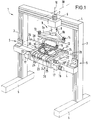
- the device for looping a pretzel shown schematically in FIG. 1 has a base frame 1, which is connected to the struts 3 by two foot struts 2 arranged parallel to one another, two struts 3 connected to them, extending vertically to them, and two spaced-apart parallel to one another , horizontally arranged struts 4 is formed. While the upper strut 4 rests on the struts 3 in the plane of the struts 3, the lower strut 4 is arranged to the side of the two struts 3 and is connected to them via two angle irons 5. On half the length of the upper strut 4, a cuboid bearing flange 6 is attached to the upper strut 4 above the lower strut 4.
- An electric swivel motor 7 is connected to the bearing flange 6, with the lower free end of the vertically directed drive shaft 8 of the electric swivel motor 7, a two-armed lever 9 is fixedly connected.
- a two-armed lever 9 is fixedly connected.
- the lever arms 9a and 9b are inclined downward from the horizontal by an angle of approximately 15 ° (see, for example, FIG. 2).
- the two lever arms 9a and 9b of the lever 9 are arranged symmetrically to a plane formed by the pivot axis 10 and the perpendicular to this, horizontally oriented axis 30, so that the free ends of the lever arms 9a and 9b during a pivoting movement of the lever 9 in one common horizontal plane.
- two single-armed levers 11 and 12 are also provided, one lever 11 and 12 each being pivotally connected to the end of the lever arm 9a and 9b.
- the pivotable connection is made by means of an electric swivel motor 13 or 14, which is connected to the free end of the lever arm 9a or 9b, the drive shaft 15 (see, for example, FIG. 2) arranged inclined from the vertical and with the drive shaft 15 the respective one one-armed lever 11 or 12 is firmly connected.
- the respective lever 11 or 12 receives gripping pliers 16 (see, for example, FIG. 2), the two pliers jaws 31 and 32 of which are pneumatically movable in a manner not shown, for example.
- the pliers opening formed by the respective two jaws 31, 32 is directed essentially downwards.
- the levers 11 and 12 are oriented parallel to the lever arms 9a and 9b of the two-armed lever 9.
- the levers 11 and 12 based on their starting position shown in FIG. 2, are inclined downward from the horizontal, viewed from their pivot point, by an angle of 15 °.
- two bearing flanges 17 are fixedly connected to it and spaced apart from one another.
- a further electric swivel motor 18 is connected to one of the bearing flanges 17, the drive shaft 19 of which is oriented parallel to the lower strut 4 (see for example FIG. 2) is also mounted in the opposite bearing flange 17.
- the frame 20 of a conveyor belt is arranged between the spaced-apart bearing flanges 17, the drive shaft 19 of the swivel motor 18 receiving the frame 20 in a rotationally fixed manner.
- the frame 20 has two L-shaped side plates 22 which are connected by means of two webs 23, only one of which is shown.
- the roller 24 closest to the swivel motor 18 can be driven by means of a further electrical swivel motor 26 ′, which is firmly connected to the long section of a side plate 22.
- a further electrical swivel motor 26 ′ which is firmly connected to the long section of a side plate 22.
- the conveying plane of the drive belts 25 is horizontal.
- the drive belts 25 extend above the lower strut 4 in the space between the upper strut 4 and the two lateral struts 3.
- the two-armed lever 9 Above the frame 20 there is arranged the two-armed lever 9, the pivot axis 10 of which the plane of symmetry of the frame 20 or the conveyor belt 21 coincides.
- the conveyor belt 21 forms a section of a base for receiving a strand of dough, two further sections of the base are formed by the table parts 26 and 27 on both sides of the conveyor belt 11.
- the table parts 26 and 27 are located between the conveyor belt 21 and the side struts 3, they also extend away from the lower strut 4. In this area, facing away from the lower strut 4, each table part 26 or 27 has a longitudinal groove arranged parallel to the strut 4 shallow depth, the level of which corresponds to the conveying plane of the drive belt 25.
- the device described so far with reference to the illustration in FIG. 1 and additionally with reference to FIGS. 2 and 3 serves to loop a pretzel from a straight strand of dough 29, which is deposited from a machine into the longitudinal grooves 28 of the table parts 26 and 27 and between them onto the drive belt 25 becomes.
- the dough strand 29 has a larger cross section in the middle section than in the end regions, as is illustrated in FIG. 1 for the partially looped pretzel.
- the distance between the ends of the longitudinal grooves 28 facing away from each other specifies the maximum length of dough strand.
- FIGS. 2 to 14 Figures 2 and 3 show the straight dough strand 29, which rests on the conveyor belt 21 and the table parts 26 and 27, which is not in the raised position, is specifically inserted into the longitudinal grooves 28 of the table parts 26 and 27, so that a defined position of the straight dough strand 29 is specified.
- the two-armed lever 9 is in its starting position, as is illustrated in FIG. 1, and the two one-armed levers 11 and 12 are also in their starting positions, in which the free end of the respective lever 11 or 12 is separated from the other lever 12 or 11 is directed away and is slightly overstretched against the V-sector of the two-armed lever 9, for example by an angle of 10 °.
- the two gripper tongs 16 have been moved pneumatically in such a way that their downward-facing jaws 31 and 32 grip the free end 33 and 34 of the straight dough strand 29 in a clamped manner.
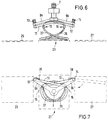
- the lever 12 is accordingly transferred into its end position, which is illustrated in the illustration in FIGS. 6 and 7.
- the electric swivel motor 14 is activated, which moves the lever 12 against a further stop 38 on the lever 9.
- the end regions of the halves of the dough strand 36 and 37 lie one above the other and touch.
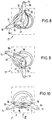
- FIGS. 8, 9 and 10 illustrate the further looping process of the pretzel for the central region of FIG. 7, FIG. 7 showing the situation after a pivoting movement of the lever 9 by an angle of 60 ° from the starting position, and FIG. 9 a pivoting angle of 120 ° and FIG. 10 is one of 180 °, which at the same time illustrates the end position of the lever 9.
- the gripping tongs 16 are arranged at a distance from the conveyor plane of the conveyor belt 21.
- the side view according to FIG. 12 also illustrates this.
- the conveyor belt 21 by activating the electric swivel motor 18 so far folded up about the axis 19 until the gripper the two ends of the dough strand 29 in the central areas of the Press in pretzel oval.
- the jaws 31 and 32 of the gripper tongs 16 are opened and the conveyor belt 21 is lowered again into its position shown in FIG.
- FIGS. 12, 13 and 14 clarify that in accordance with the inner contour sections of the looped pretzel 39, contact marks 40 arranged in an end position above the conveying level of the drive belts 25 are arranged between them and thus ensure a constant shape of the pretzel 39 when looping.
- the contact marks 40 are connected to a plate 41 which is arranged below the upper run of the drive belt 25 and which can be moved downward from this run by means of a pneumatic cylinder 42, so that the contact marks are in their end position below the conveying level of the drive belt 25.
- the finished looped pretzel 29 can then be conveyed through the contact marks 40 without hindrance, as shown in the illustration in FIG.
Abstract
Description
Die Erfindung betrifft eine Vorrichtung zum Schlingen eines Brezels aus einem geraden Teigstrang definierter Länge.The invention relates to a device for looping a pretzel from a straight strand of dough of a defined length.
Aus der US-PS 2 629 340 ist eine Vorrichtung bekannt, die dem Schlingen eines Brezels aus einem geraden Teigstrang definierter Länge dient. Der Vorrichtung werden zwischen zwei Transportbändern gerade Teigstränge zugefördert, die über ihre Stranglänge einen konstanten Querschnitt aufweisen. Es ist eine Aufnahme für den geraden Teigstrang vorgesehen, mit erhabenen Elementen, um die der Teigstrang nach dem Ergreifen der Strangenden mittels zweier Greifer zur Bildung des Brezels gelegt wird. Die die Schlingbewegung des Teigstranges vollführenden Greifer werden über eine geometrisch kompliziert gestaltete Kurve angesteuert, derart, daß sie sowohl eine Bewegung in horizontaler als auch in vertikaler Richtung, wobei diese Bewegungen durchaus auch überlagert sind, vollführen. So zieht zunächst der eine Greifer die eine Hälfte des Teigstranges, nachfolgend der Einfachheit halber erste Teigstranghälfte genannt, entlang eines Bogens in Richtung der horizontalen Symmetrieachse des geraden Teigstranges und hebt dabei diese erste Teigstranghälfte an. Während dieses Bewegungsablaufes bewegt der zweite Greifer die andere Hälfte des Teigstranges, nachfolgend der Einfachheit halber als zweite Teigstranghälfte bezeichnet, in einem Bogen bei gleichzeitiger Hubbewegung unter die erste Teigstranghälfte, so daß sich die beiden Teigstranghälften in ihren Endbereichen überlappen. Es zieht dann der der zweiten Teigstranghälfte zugeordnete Greifer das Ende der zweiten Teigstranghälfte in Richtung der Teigstrangmitte, wobei die erste Teigstranghälfte in Richtung der Teigstrangmitte zur Bildung eines brezelförmigen Ovals gezogen wird. Schließlich legt der das Ende der zweiten Teigstranghälfte haltende Greifer dieses Ende entsprechend der gewünschten Brezelform in dem Bereich des Teigstranges ab, der dem Berührungsbereich der beiden Teigstranghälften gegenüberliegt. Der die erste Teigstranghälfte erfassende Greifer wird so bewegt, daß sich die erste Teigstranghälfte über die zweite Teigstranghälfte legt, womit im Berührungspunkt der beiden Teigstranghälften die Schlingung erfolgt. Das Ende der ersten Teigstranghälfte wird entsprechend mittels des diesem Ende zugeordneten Greifers auf dem Mittelbereich des Teigstranges abgelegt. Nachdem so der Brezel aus dem Teigstrang geschlungen und die Strangenden auf den Mittelbereich des Teigstranges abgelegt sind, werden über die Kurve zwei Stempel angesteuert, die sich auf die Enden der Teigstranghälften absenken und diese in die zugeordneten Mittelbereiche des Teigstranges eindrücken, so daß eine Verbindung zwischen den beiden Enden und den Mittelbereichen des Teigstranges erfolgt.A device is known from US Pat. No. 2,629,340 which is used to loop a pretzel from a straight strand of dough of a defined length. The device is fed straight strands of dough between two conveyor belts, which have a constant cross section over their strand length. There is a receptacle for the straight strand of dough, with raised elements to the dough strand is placed after grasping the strand ends by means of two grippers to form the pretzel. The grippers carrying out the wrap movement of the dough strand are controlled via a geometrically complicated curve, in such a way that they carry out a movement both in the horizontal and in the vertical direction, these movements also being superimposed. First of all, the one gripper pulls one half of the dough strand, hereinafter called the first half of the dough strand for the sake of simplicity, along an arc in the direction of the horizontal axis of symmetry of the straight dough strand and lifts this first half of the dough strand. During this movement sequence, the second gripper moves the other half of the dough strand, hereinafter referred to simply as the second dough strand half, in an arc with a simultaneous lifting movement under the first dough strand half, so that the two dough strand halves overlap in their end regions. The gripper assigned to the second half of the dough strand then pulls the end of the second half of the dough strand towards the middle of the dough strand, the first half of the dough strand being pulled towards the middle of the dough strand to form a pretzel-shaped oval. Finally, the gripper, which holds the end of the second half of the dough strand, deposits this end according to the desired pretzel shape in the region of the dough strand which lies opposite the contact area of the two halves of the dough strand. The gripper, which grips the first half of the dough strand, is moved such that the first half of the dough strand lies over the second half of the dough strand, so that the looping takes place at the point of contact of the two halves of the dough strand. The end of the first half of the dough strand is accordingly deposited on the middle region of the dough strand by means of the gripper assigned to this end. After the pretzel is looped out of the dough strand and the ends of the strand are placed on the middle area of the dough strand, two stamps are driven over the curve, which lower onto the ends of the halves of the dough strand and press them into the assigned middle areas of the dough strand, so that a connection between the two ends and the central areas of the dough strand.
Aus der DE 17 82 289 B2 ist eine Vorrichtung bekannt, die dem Schlingen eines Brezels aus einem in U-Form vorliegenden Teigstrang definierter Länge dient. Bei dieser Vorrichtung werden die Enden des U-förmigen Teigstranges mittels je eines an einem zugeordneten Hebel befestigten Greifers erfaßt. Die beiden einarmigen Hebel sind unabhängig voneinander um eine gemeinsame, senkrecht zur Ebene des Teigstranges angeordnete Achse um mindestens 180° schwenkbar sowie axial hin- und herbeweglich, das heißt die Greifer sind anhebbar- bzw. absenkbar. Während des gleichzeitig erfolgenden Schwenkens der Greifer wird der U-förmige Teigstrang zum fertigen Brezel geschlungen und am Ende der Schwenkbewegung werden die Teigstrangenden durch Absenken der Greifer auf das Mittelstück des Teigstranges abgesetzt. Die Hebel sind um eine gemeinsame Achse schwenkbar, wobei einer der Hebel mit einer Hohlwelle und der andere Hebel mit einer die Hohlwelle durchsetzenden Welle verbunden ist. Auf- und abbewegliche Niederhalter mit entsprechend der Brezelform und dem jeweiligen Durchmesser des Teigstranges angeordneten Krallen sichern die Lage des Teigstranges während des Schlingvorganges.From DE 17 82 289 B2 a device is known which is used for looping a pretzel from a strand of dough of a defined length in a U-shape. In this device, the ends of the U-shaped dough strand are gripped by means of a gripper each attached to an associated lever. The two one-armed levers can be pivoted independently of one another about a common axis arranged perpendicular to the plane of the dough strand by at least 180 ° and can be moved axially back and forth, that is to say the grippers can be raised or lowered. During the simultaneous swiveling of the grippers, the U-shaped strand of dough is looped to the finished pretzel and at the end of the swiveling movement, the ends of the dough are lowered onto the middle part of the strand of dough by lowering the grippers. The levers can be pivoted about a common axis, one of the levers being connected to a hollow shaft and the other lever being connected to a shaft passing through the hollow shaft. Hold-down devices movable up and down with claws arranged in accordance with the pretzel shape and the respective diameter of the dough strand secure the position of the dough strand during the slinging process.
Aufgabe der vorliegenden Erfindung ist es, eine Vorrichtung zum Schlingen von Brezeln zu schaffen, die baulich besonders einfach gestaltet ist und auch zum Schlingen von Brezeln unterschiedlichen Strangquerschnittes geeignet ist.The object of the present invention is to create a device for looping pretzels, which is structurally particularly simple and is also suitable for looping pretzels of different strand cross-sections.
Die Erfindung schlägt hierzu eine Vorrichtung vor, mit
- einer Unterlage zur Aufnahme des Teigstranges, wobei ein der Aufnahme des geschlungenen Brezels dienender Abschnitt der Unterlage aus einer im wesentlichen horizontalen Lage anhebbar ist,
- einem oberhalb des Abschnitts der Unterlage angeordneten, zweiarmigen Hebel, der um eine vertikale Achse schwenkbar ist, wobei sich das jeweilige freie Ende des zweiarmigen Hebels in einem Bogen in einer horizontalen Ebene bewegt,
- zwei einarmigen Hebeln, wobei jeweils ein Hebel mit einem Hebelarmende des zweiarmigen Hebelarms schwenkbar verbunden ist und im wesentlichen um eine aus der Vertikalen geneigte Achse schwenkbar ist, und im Bereich seines der Schwenkachse abgewandten Endes ein Greifelement aufnimmt,
- a base for receiving the strand of dough, a portion of the base serving to accommodate the looped pretzel being liftable from a substantially horizontal position,
- a two-armed lever arranged above the section of the support, which can be pivoted about a vertical axis, the respective free end of the two-armed lever moving in an arc in a horizontal plane,
- two one-armed levers, one lever being pivotally connected to a lever arm end of the two-armed lever arm and essentially being inclined from the vertical Axis is pivotable, and receives a gripping element in the region of its end facing away from the pivot axis,
Bei in Ausgangsstellung befindlichem zweiarmigem Hebel wird einer der einarmigen Hebel aus seiner Ausgangsstellung in seine Endstellung bewegt, wobei das vom Greifelement erfaßte Ende der ersten Teigstranghälfte im Bogen bewegt wird und dabei wegen der aus der vertikalen geneigten Schwenkachse des einarmigen Hebels von der Unterlage angehoben wird. Während oder nach der Schwenkbewegung des die erste Teigstranghälfte bewegenden einarmigen Hebels wird der andere einarmige Hebel verschwenkt, entsprechend vollführt das Ende der zweiten Teigstranghälfte eine Bewegung entlang eines Bogens in Richtung der anderen Teigstranghälfte und wird dabei gleichfalls von der Unterlage abgehoben. Die Geometrie ist dabei so bemessen, daß die beiden einarmigen Hebel nicht miteinander kollidieren. Es wird als bevorzugt angesehen, wenn die zweite Teigstranghälfte unterhalb der ersten Teigstranghälfte hindurchgeführt wird, wobei sich die weitgehend entsprechend dem Oval des Brezels darstellenden Teigstranghälften in der Endstellung der beiden einarmigen Hebel im Überlappungsbereich berühren. Sobald die beiden einarmigen Hebel deren Endstellung erreicht haben, wird der zweiarmige Hebel um etwa 180° geschwenkt, womit die bisher nur übereinanderliegenden Teigstranghälften im Überlappungsbereich miteinander verschlungen werden. Nachdem der zweiarmige Hebel seine Endstellung erreicht hat, befinden sich die beiden Greifer und damit auch die beiden Enden des Teigstranges beabstandet zum Oval des Brezels. Um die Enden des Teigstranges mit den Mittenbereichen des Ovals zu verbinden, ist nun vorgesehen, daß zumindest derjenige Abschnitt der Unterlage, der der Aufnahme des geschlungenen Brezels dient, aus seiner im wesentlichen horizontalen Lage anhebbar ist. In der angehobenen Endstellung drücken die Greifelemente die Enden des Teigstranges in dessen Mittenbereiche. Nachdem der Brezel so geschlungen und die Teigstrangenden mit dem Teigstrang verbunden sind, können die Greifelemente geöffnet und die Unterlage in ihrer Ausgangsstellung zurückbewegt werden, sodann der fertig geschlungene Brezel aus der Vorrichtung entnommen werden.When the two-armed lever is in the starting position, one of the one-armed levers is moved from its starting position into its end position, the end of the first half of the dough strand gripped by the gripping element being moved in an arc and being lifted from the base because of the vertical inclined pivot axis of the one-armed lever. During or after the pivoting movement of the one-armed lever moving the first half of the dough strand, the other one-armed lever is pivoted; accordingly, the end of the second half of the dough strand moves along an arc in the direction of the other half of the dough strand and is also lifted off the base. The geometry is such that the two one-armed levers do not collide with each other. It is considered preferred if the second half of the dough strand is passed below the first half of the dough strand, the halves of the dough strand largely corresponding to the oval of the pretzel touching in the end position of the two one-armed levers in the overlap region. As soon as the two one-armed levers have reached their end position, the two-armed lever is pivoted by about 180 °, which means that the hitherto only superimposed ones Halves of the dough are intertwined in the overlap area. After the two-armed lever has reached its end position, the two grippers and thus the two ends of the dough strand are at a distance from the oval of the pretzel. In order to connect the ends of the dough strand to the central regions of the oval, it is now provided that at least that portion of the base which serves to hold the looped pretzel can be lifted out of its essentially horizontal position. In the raised end position, the gripping elements press the ends of the strand of dough in its central areas. After the pretzel has been looped in this way and the ends of the dough strand have been connected to the dough strand, the gripping elements can be opened and the base can be moved back to its starting position, and the finished pretzel can then be removed from the device.
Die Vorrichtung zeichnet sich somit durch eine äußerst einfache Gestaltung der Bauelemente, nämlich der Unterlage, des zweiarmigen Hebels und der beiden einarmigen Hebel mit den Greifelementen aus, wobei aufgrund der kinematischen Verhältnisse ein einfaches und schnelles Schlingen des Brezels möglich ist.The device is thus characterized by an extremely simple design of the components, namely the base, the two-armed lever and the two one-armed lever with the gripping elements, with the kinematic conditions allowing the pretzel to be looped easily and quickly.
Gemäß einer besonderen Ausführungsform der Erfindung ist vorgesehen, daß der zweiarmige Hebel und/oder jeder der beiden einarmigen Hebel mittels eines eigenen Motors schwenkbar sind. Hierdurch können die Bewegungen des zweiarmigen Hebels und jedes der beiden einarmigen Hebel unabhängig voneinander erfolgen. Vorteilhaft ist der jeweilige Motor als elektrischer Schwenkmotor ausgebildet, der in seinem Schwenkwinkel entsprechend dem des zweiarmigen bzw. der einarmigen Hebel begrenzt ist.According to a special embodiment of the invention it is provided that the two-armed lever and / or each of the two one-armed lever can be pivoted by means of its own motor. As a result, the movements of the two-armed lever and each of the two one-armed levers can take place independently of one another. The respective motor is advantageously designed as an electric swivel motor which is limited in its swivel angle in accordance with that of the two-armed or one-armed lever.
Zweckmäßig weist die Vorrichtung einen Grundrahmen auf, wobei mit einer horizontalen Strebe des Grundrahmens der Motor für den zweiarmigen Hebel verbunden ist, mit dessen vertikal gerichteter Antriebswelle der zweiarmige Hebel verbunden ist. Ferner ist vorgesehen, daß mit dem jeweiligen freien Ende des zweiarmigen Hebels der Motor zum Verschwenken des zugeordneten einarmigen Hebels verbunden ist, wobei dessen Antriebswelle aus der Vertikalen geneigt angeordnet und mit der Antriebswelle der einarmige Hebel verbunden ist.The device expediently has a base frame, the motor for the two-armed lever being connected to a horizontal strut of the base frame, the vertically directed drive shaft of which is connected to the two-armed lever. It is further provided that the motor for pivoting the associated one-armed with the respective free end of the two-armed lever Lever is connected, the drive shaft is arranged inclined from the vertical and connected to the drive shaft of the one-armed lever.
Die Hubbewegung der Greifelemente läßt sich auf einfachste Art und Weise optimal darstellen, wenn die Arme des zweiarmigen Hebels, ausgehend von dessen Schwenkachse, um einen Winkel von etwa 15° aus der Horizontalen nach unten geneigt sind und die Antriebswelle des die Schwenkbewegung des jeweiligen einarmigen Hebels bewerkstelligenden Motors senkrecht zum zugeordneten Arm des zweiarmigen Hebels angeordnet ist, sowie der zugeordnete einarmige Hebel, ausgehend von dessen Schwenkachse, um einen Winkel von etwa 15° aus der Horizontalen nach unten geneigt ist.The stroke movement of the gripping elements can be optimally represented in the simplest way if the arms of the two-armed lever, starting from its pivot axis, are inclined downwards by an angle of approximately 15 ° from the horizontal and the drive shaft of the pivoting movement of the respective one-armed lever producing motor is arranged perpendicular to the associated arm of the two-armed lever, and the associated one-armed lever, starting from its pivot axis, is inclined downward by an angle of approximately 15 ° from the horizontal.
Vorteilhaft ist das jeweilige Greifelement als Greifzange ausgebildet, deren Zangenöffnung im wesentlichen nach unten gerichtet ist. Die Anordnung der Zangenöffnung gestattet es, das jeweilige Ende des gerade positionierten Teigstranges einfach zu greifen und auch dieses Ende nach dem Schlingen des Brezels in den Mittenbereich des Teigstranges einzudrücken.The respective gripping element is advantageously designed as gripping pliers, the pliers opening of which is directed essentially downwards. The arrangement of the tongs opening makes it easy to grip the respective end of the dough strand just positioned and to press this end into the middle region of the dough strand after the pretzel is looped.
Besonders einfache kinematische Verhältnisse beim Schlingen des Brezels ergeben sich, wenn die beiden Arme des zweiarmigen Hebels nicht unter einem Winkel von 180°, sondern einem solchen von etwa 120° zueinander angeordnet sind. In diesem Fall erfolgt bei in Ausgangsstellung befindlichem zweiarmigem Hebel vorteilhaft das Überlappen der beiden Teigstranghälften im V-Sektor des Hebels, so daß nach dem Überführen des zweiarmigen Hebels in dessen Endstellung die geschlungenen Teigstranghälften mit ihren Strangenden von der einen Ovalhälfte in die andere Ovalhälfte bewegt werden. Bei einer solchen Ausbildung sollte der jeweilige einarmige Hebel relativ zum zugeordneten Hebelarmende des zweiarmigen Hebels um einen Winkel von etwa 160° schwenkbar sein. Zweckmäßig wird der Schwenkbereich des jeweiligen einarmigen Hebels in seiner Ausgangs- und/oder Endstellung durch einen zwischen diesem Hebel und dem zweiarmigen Hebel wirksamen Anschlag begrenzt.Particularly simple kinematic conditions when looping the pretzel result if the two arms of the two-armed lever are not arranged at an angle of 180 ° but at an angle of approximately 120 ° to one another. In this case, when the two-armed lever is in the starting position, the two halves of the dough strand advantageously overlap in the V-sector of the lever, so that after the two-armed lever has been transferred into its end position, the looped halves of the dough strand with their ends of the strands are moved from one oval half to the other oval half . With such a design, the respective one-armed lever should be pivotable through an angle of approximately 160 ° relative to the associated lever arm end of the two-armed lever. The pivoting range of the respective one-armed lever is expediently limited in its starting and / or end position by a stop acting between this lever and the two-armed lever.
Eine besondere Ausführungsform der Erfindung sieht vor, daß der hebbare, der Aufnahme des geschlungenen Brezels dienende Abschnitt der Unterlage um eine parallel zum geraden Teigstrang angeordnete Achse schwenkbar ist. Bei nach dem Überführen der einarmigen Hebel sowie des zweiarmigen Hebels in deren jeweilige Endstellung erfolgenden Hochschwenken des Abschnittes der Unterlage von dessen im wesentlichen horizontaler Ausgangsstellung in dessen Endstellung werden so die von den beiden Greifelementen ergriffenen Teigstrangenden in den diesen zugeordneten Mittelabschnitt des geschlungenen Teigstrangs gedrückt. Um den geschlungenen Brezel dem weiteren Herstellungsprozeß zuführen zu können ist vorgesehen, daß der Abschnitt der Unterlage als Förderband ausgebildet ist, dessen Förderrichtung senkrecht zur Erstreckung des geraden Teigstrangs gerichtet ist. Das Förderband besteht zweckmäßig aus einzelnen, beabstandet zueinander angeordneten Treibriemen, wobei entsprechend Innenkonturabschnitten des geschlungenen Brezels angeordnete Anlegemarken aus einer Ausgangsstellung unterhalb des Förderniveaus des Förderbandes in eine Endstellung oberhalb des Förderniveaus zwischen die Treibriemen verfahrbar sind. Beim Schlingen des Brezels, das heißt ausgehend von dem geraden Teigstrang dienen die Anlegemarken der Führung der Teigstranghälften, nachdem der Brezel fertig geschlungen ist werden die Anlegemarken unter das Förderniveau des Förderbandes abgesenkt, so daß der Brezel mittels des Förderbandes abgefördert werden kann.A special embodiment of the invention provides that the liftable portion of the base which serves to hold the looped pretzel can be pivoted about an axis arranged parallel to the straight strand of dough. When after the transfer of the one-armed lever and the two-armed lever into their respective end position, the portion of the base swings up from its substantially horizontal starting position into its end position, the ends of the dough strands gripped by the two gripping elements are pressed into the associated middle section of the looped dough strand. In order to be able to feed the looped pretzel to the further manufacturing process, it is provided that the section of the base is designed as a conveyor belt, the conveying direction of which is directed perpendicular to the extension of the straight strand of dough. The conveyor belt expediently consists of individual drive belts which are arranged at a distance from one another, with contact marks arranged in accordance with inner contour sections of the looped pretzel being movable between the drive belts from an initial position below the conveyor level of the conveyor belt to an end position above the conveyor level. When looping the pretzel, that is, starting from the straight strand of dough, the lay-on marks serve to guide the halves of the dough strand, after the pretzel has been wrapped, the lay-on marks are lowered below the conveying level of the conveyor belt, so that the pretzel can be conveyed away by means of the conveyor belt.
Die Erfindung schlägt damit eine besonders einfach gebaute Vorrichtung zum Schlingen eines Brezels aus einem geraden Teigstrang definierter Länge vor, wobei dieser Teigstrang durchaus unterschiedliche Dicke aufweisen kann.The invention thus proposes a particularly simple device for looping a pretzel from a straight strand of dough of a defined length, which strand of dough can have different thicknesses.
Weitere Merkmale der Erfindung sind in der Figurenbeschreibung und den Patentansprüchen dargestellt, wobei bemerkt wird, daß alle Merkmale und Kombinationen von Merkmalen erfindungswesentlich sind.Further features of the invention are shown in the description of the figures and the claims, it being noted that all features and combinations of features are essential to the invention.
In den Figuren ist die Erfindung anhand einer Ausführungsform dargestellt, ohne auf diese beschränkt zu sein. Es zeigt in schematischer Darstellung:
Figur 1- eine räumliche Ansicht der erfindungsgemäßen Vorrichtung während des Schlingens eines Brezels bei in Endstellung befindlichem zweiarmigen Hebel und in Endstellung befindlichen einarmigen Hebeln sowie nicht angehobenem Abschnitt der Unterlagen,
- Figur 2
- eine Seitenansicht der für die Darstellung der kinematischen Verhältnisse der Vorrichtung relevanten Bauteile, gezeigt bei in Ausgangsstellung befindlichem zweiarmigem Hebel und den beiden in Ausgangsstellung befindlichen einarmigen Hebeln,
Figur 3- eine Ansicht in Richtung III-III gemäß Figur 2 gesehen,
Figur 4- eine Seitenansicht gemäß Figur 2, wobei jedoch der der ersten Teigstranghälfte zugeordnete erste einarmige Hebel sich in seiner Endstellung befindet,
Figur 5- eine Draufsicht des Zustandes nach Figur 4, entsprechend der Darstellung in
Figur 3 verdeutlicht, Figur 6- eine Seitenansicht gemäß Figur 4, wobei jedoch der der zweiten Teigstranghälfte zugeordnete zweite einarmige Hebel sich in seiner Endstellung befindet,
Figur 7- eine Draufsicht des Zustands nach Figur 6, entsprechend der Darstellung nach Figur 3 verdeutlicht,
Figuren und 10- Draufsichten des Zustands beim Überführen des zweiarmigen Hebels in seine Endstellung, verdeutlicht bei einem Schwenkwinkel aus der Ausgangsstellung um 60° (Figur 8), um 120° (Figur 9) und um 180° (Endstellung gemäß Figur 10),
Figur 11- eine Seitenansicht bei in Endstellung befindlichen einarmigen Hebeln und in Endstellung befindlichem zweiarmigem Hebel gemäß Pfeil XI in
Figur 10, Figur 12- eine Seitenansicht gemäß Pfeil XII in
Figur 11 mit einer detaillierteren Darstellung des als Förderband ausgebildeten Abschnittes der Unterlage, gezeigt in nicht angehobener Stellung dieses Abschnittes, Figur 13- eine Darstellung gemäß Figur 12, jedoch bei angehobenem, das heißt hochgeschwenktem Förderband und
Figur 14- eine Draufsicht des auf dem Förderband aufliegenden geschlungenen Brezels, wobei dieser Darstellung die eingeschwenkte Stellung des Förderbandes zugrundegelegt ist.
- Figure 1
- 2 shows a three-dimensional view of the device according to the invention during the looping of a pretzel with the two-armed lever in the end position and the one-armed lever in the end position, as well as the section of the documents not raised
- Figure 2
- 2 shows a side view of the components relevant for the representation of the kinematic relationships of the device, shown with the two-armed lever in the starting position and the two one-armed levers in the starting position,
- Figure 3
- seen a view in the direction III-III according to Figure 2,
- Figure 4
- 3 shows a side view according to FIG. 2, but the first one-armed lever assigned to the first half of the dough strand is in its end position,
- Figure 5
- 3 shows a plan view of the state according to FIG. 4, as illustrated in FIG. 3,
- Figure 6
- 3 shows a side view according to FIG. 4, but the second one-armed lever assigned to the second half of the strand of dough is in its end position,
- Figure 7
- 6 shows a top view of the state according to FIG. 6, corresponding to the representation according to FIG.
- Figures 8, 9 and 10
- Top views of the state when moving the two-armed lever into its end position, illustrated with a swivel angle from the starting position by 60 ° (FIG. 8), by 120 ° (FIG. 9) and by 180 ° (end position according to FIG. 10),
- Figure 11
- 10 shows a side view with one-armed levers in the end position and two-armed lever in the end position according to arrow XI in FIG. 10,
- Figure 12
- 11 shows a side view according to arrow XII in FIG. 11 with a more detailed illustration of the section of the support formed as a conveyor belt, shown in the non-raised position of this section,
- Figure 13
- a representation according to Figure 12, but with the conveyor belt raised and that is swung up
- Figure 14
- a plan view of the looped pretzel lying on the conveyor belt, this representation is based on the pivoted position of the conveyor belt.
Die in Figur 1 schematisch dargestellte Vorrichtung zum Schlingen eines Brezels weist einen Grundrahmen 1 auf, der durch zwei parallel zueinander angeordnete Fußstreben 2, zwei mit diesen verbundene, sich vertikal zu diesen erstreckende Streben 3 und zwei parallel zueinander beabstandet angeordnete, mit den Streben 3 verbundene, horizontal angeordnete Streben 4 gebildet ist. Während die obere Strebe 4 in der Ebene der Streben 3 auf diesen aufliegt, ist die untere Strebe 4 seitlich der beiden Streben 3 angeordnet und mit diesen über zwei Winkeleisen 5 verbunden. Auf der halben Länge der oberen Strebe 4 ist oberhalb der unteren Strebe 4 ein quaderförmiger Lagerflansch 6 mit der oberen Strebe 4 befestigt. Ein elektrischer Schwenkmotor 7 ist mit dem Lagerflansch 6 verbunden, mit dem unteren freien Ende der vertikal gerichteten Antriebswelle 8 des elektrischen Schwenkmotors 7 ist ein zweiarmiger Hebel 9 fest verbunden. Dessen beide Hebelarme 9a und 9b sind von der durch die Streben 3 und die obere Strebe 4 gebildeten Ebene weggerichtet und schließen einen Winkel von 120° miteinander ein. Darüber hinaus sind die Hebelarme 9a und 9b, ausgehend von der Schwenkachse 10 des zweiarmigen Hebels 9, um einen Winkel von etwa 15° aus der Horizontalen nach unten geneigt (siehe beispielsweise Figur 2). Die beiden Hebelarme 9a und 9b des Hebels 9 sind symmetrisch zu einer durch die Schwenkachse 10 und die senkrecht zu dieser verlaufenden, horizontal orientierten Achse 30 gebildeten Ebene angeordnet, so daß die freien Enden der Hebelarme 9a und 9b bei einer Schwenkbewegung des Hebels 9 in einer gemeinsamen horizontalen Ebene bewegt werden.The device for looping a pretzel shown schematically in FIG. 1 has a
Wie die Figur 1 verdeutlicht, sind ferner zwei einarmige Hebel 11 und 12 vorgesehen, wobei jeweils ein Hebel 11 bzw. 12 mit dem Ende des Hebelarms 9a bzw. 9b schwenkbar verbunden ist. Die schwenkbare Verbindung erfolgt mittels jeweils eines elektrischen Schwenkmotores 13 bzw. 14, der mit dem freien Ende des Hebelarmes 9a bzw. 9b verbunden ist, wobei dessen Antriebswelle 15 (siehe beispielsweise Figur 2) aus der Vertikalen geneigt angeordnet und mit der Antriebswelle 15 der jeweilige einarmige Hebel 11 bzw. 12 fest verbunden ist. Im Bereich seines freien Endes nimmt der jeweilige Hebel 11 bzw. 12 eine Greifzange 16 auf (siehe beispielsweise Figur 2) deren beide Zangenbacken 31 bzw. 32 in nicht näher dargestellter Art und Weise beispielsweise pneumatisch bewegbar sind. Die durch die jeweiligen beiden Zangenbacken 31, 32 gebildete Zangenöffnung ist im wesentlichen nach unten gerichtet.As illustrated in FIG. 1, two single-
Wie beispielsweise der Darstellung der Figur 2 zu entnehmen ist, sind die Hebel 11 und 12 parallel zu den Hebelarmen 9a bzw. 9b des zweiarmigen Hebels 9 orientiert. Damit sind die Hebel 11 und 12, bezogen auf deren in Figur 2 gezeigte Ausgangsstellung, von deren Schwenkpunkt gesehen um einen Winkel von 15° aus der Horizontalen nach unten geneigt.As can be seen, for example, from the illustration in FIG. 2, the
Vor der unteren Strebe 4 sind zwei mit dieser fest verbundene, beabstandet zueinander angeordnete Lagerflansche 17 befestigt. Mit einem der Lagerflansche 17 ist ein weiterer elektrischer Schwenkmotor 18 verbunden, dessen parallel zur unteren Strebe 4 orientierte Anriebswelle 19 (siehe beispielsweise Figur 2) auch im gegenüberliegenden Lagerflansch 17 gelagert ist. Zwischen den beabstandet zueinander angeordneten Lagerflanschen 17 ist der Rahmen 20 eines Förderbandes angeordnet, wobei die Antriebswelle 19 des Schwenkmotores 18 den Rahmen 20 drehfest aufnimmt. Der Rahmen 20 weist zwei L-förmigen Seitenplatten 22 auf, die mittels zweier Stege 23, von denen nur einer gezeigt ist, verbunden sind. Die drehfeste Verbindung der Antriebswelle 19 mit dem Rahmen 20 erfolgt im Bereich des kurzen Schenkels der L-förmigen Seitenplatten 22. Zwischen den beiden langen Schenkeln der Seitenplatten 22 sind zwei Walzen 24 drehbar gelagert, die ein Förderband aufnehmen, das aus einzelnen, beabstandet zueinander angeordneten Treibriemen 25 gebildet ist.In front of the
Die dem Schwenkmotor 18 nächstliegende Walze 24 ist mittels eines weiteren elektrischen Schwenkmotors 26' antreibbar, der mit dem langen Abschnitt einer Seitenplatte 22 fest verbunden ist. In der in Figur 1 gezeigten, nicht angehobenen, das heißt nicht ausgeschwenkten Position des Rahmens 20 liegt die Förderebene der Treibriemen 25 horizontal.The
Wie der Darstellung der Figur 1 zu entnehmen ist, erstrecken sich die Treibriemen 25 oberhalb der unteren Strebe 4 in dem Raum zwischen der oberen Strebe 4 und den beiden seitlichen Streben 3. Oberhalb des Rahmens 20 ist der zweiarmige Hebel 9 angeordnet, dessen Schwenkachse 10 mit der Symmetrieebene des Rahmens 20 bzw. des Förderbandes 21 zusammenfällt. Das Förderband 21 bildet einen Abschnitt einer Unterlage zur Aufnahme eines Teigstranges, zwei weitere Abschnitte der Unterlage sind durch die Tischteile 26 und 27 beidseits des Förderbandes 11 gebildet. Die Tischteile 26 und 27 befinden sich zwischen dem Förderband 21 und den seitlichen Streben 3, sie erstrecken sich darüber hinaus von der unteren Strebe 4 weg. In diesem, der unteren Strebe 4 abgewandten Bereich weist jedes Tischteil 26 bzw. 27 eine parallel zur Strebe 4 angeordnete Längsrille geringer Tiefe auf, deren Aufnahmeniveau mit der Förderebene der Treibriemen 25 übereinstimmt.As can be seen from the illustration in FIG. 1, the
Die insoweit anhand der Darstellung der Figur 1 und ergänzend anhand der Figuren 2 und 3 beschriebene Vorrichtung dient dem Schlingen eines Brezels aus einem geraden Teigstrang 29, der aus einer Maschine in die Längsrillen 28 der Tischteile 26 und 27 und zwischen diesen auf die Treibriemen 25 abgelegt wird. Wie bei üblichen, sonst handgefertigten Laugen-Brezeln weist der Teigstrang 29 im Mittelabschnitt einen größeren Querschnitt auf als in den Endbereichen, so wie es in der Figur 1 für den teilweise geschlungenen Brezel verdeutlicht ist. Der Abstand der einander abgewandten Enden der Längsrillen 28 gibt dabei die maximale Teigstranglänge vor.The device described so far with reference to the illustration in FIG. 1 and additionally with reference to FIGS. 2 and 3 serves to loop a pretzel from a straight strand of
Der Vorgang zum Schlingen eines Brezels sei nun anhand der Darstellung der Figuren 2 bis 14 näher verdeutlicht:
Die Figuren 2 und 3 zeigen den geraden Teigstrang 29, der auf dem in nicht angehobener Stellung befindlichem Förderband 21 und den Tischteilen 26 und 27 aufliegt, konkret in die Längsrillen 28 der Tischteile 26 und 27 eingelegt ist, so daß eine definierte Position des geraden Teigstranges 29 vorgegeben ist. Der zweiarmige Hebel 9 befindet sich in seiner Ausgangsstellung, wie sie in Figur 1 verdeutlicht ist, ferner befinden sich die beiden einarmigen Hebel 11 und 12 in ihren Ausgangsstellungen, in denen das freie Ende des jeweiligen Hebels 11 bzw. 12 vom anderen Hebel 12 bzw. 11 weggerichtet und geringfügig entgegen dem V-Sektor des zweiarmigen Hebels 9 überstreckt ist, beispielsweise um einen Winkel von 10°. In dieser Position sind die beiden Greiferzangen 16 pneumatisch so bewegt worden, daß deren nach unten gerichtete Backen 31 und 32 das freie Ende 33 bzw. 34 des geraden Teigstranges 29 klemmend erfassen.The process for looping a pretzel will now be explained in more detail using the illustration in FIGS. 2 to 14:
Figures 2 and 3 show the
Ausgehend von dieser in den Figuren 2 und 3 in einer Seitenansicht und in einer Draufsicht gezeigten Ausgangsstellung wird zunächst, wie der Darstellung der Figuren 4 und 5 zu entnehmen ist, der elektrische Schwenkmotor 13 aktiviert, der den Hebel 11 um einen Winkel von etwa 160° gegen einen am Hebelarm 9a des Hebels 9 angeordneten Anschlag 35 in dessen Endstellung bewegt. Infolge der aus der horizontalen geneigten Anordnung des Hebelarmes 9a und des Hebels 11 wird die Teigstranghälfte 36 hierdurch nicht nur entlang eines Bogens bewegt, sondern der Endbereich dieser Teigstranghälfte 36 auch angehoben.Starting from this starting position, shown in FIGS. 2 and 3 in a side view and in a top view, it will first be seen from the illustration in FIGS. 4 and 5 is activated, the
Nachdem der Hebel 11 in seiner Endstellung überführt ist, wird der Hebel 12 entsprechend in seine Endstellung überführt, was in der Darstellung der Figuren 6 und 7 verdeutlicht ist. Hierzu wird der elektrische Schwenkmotor 14 aktiviert, der den Hebel 12 gegen einen weiteren Anschlag 38 am Hebel 9 bewegt. In der Endstellung der beiden Hebel 11 und 12 liegen die Endbereiche der Teigstranghälften 36 und 37 übereinander und berühren sich.After the
Nachdem die beiden Hebel 11 und 12 ihre Endstellungen erreicht haben, wird der elektrische Schwenkmotor 7 aktiviert und der zweiarmige Hebel 9 um einen Schwenkwinkel von 180° verschwenkt. Die Figuren 8, 9 und 10 verdeutlichen für den Mittelbereich der Figur 7 den weiteren Schlingprozeß des Brezels, wobei Figur 7 die Situation nach einer Schwenkbewegung des Hebels 9 um einen Winkel von 60° aus der Ausgangsstellung heraus darstellt, die Figur 9 einen Schwenkwinkel von 120° und die Figur 10 einen solchen von 180°, der gleichzeitig die Endstellung des Hebels 9 verdeutlicht. Die Seitenansicht des in Figur 10 gezeigten Zustandes nach der Darstellung in Figur 11 veranschaulicht, daß nach Erreichen der Endstellung des Hebels 9 die Greifzangen 16 beabstandet zur Förderebene des Förderbandes 21 angeordnet sind. Entsprechendes veranschaulicht auch die Seitenansicht gemäß Figur 12. Um nun die freien Enden des Teigstranges 29 in Eingriff mit den Mittelbereichen des Teigstranges, das heißt mit dem bereits etwas dickeren Bereich des Brezelovals zu bringen, wird, wie der Darstellung der Figur 13 zu entnehmen ist, das Förderband 21 durch Aktivierung des elektrischen Schwenkmotors 18 so weit um die Achse 19 hochgeklappt, bis die Greifer die beiden Enden des Teigstranges 29 in die Mittelbereiche des Brezelovals eindrücken. In der Stellung gemäß Figur 13 werden die Backen 31 und 32 der Greiferzangen 16 geöffnet und das Förderband 21 wieder in seine in Figur 12 gezeigte Position abgesenkt.After the two
Die Figuren 12, 13 und 14 verdeutlichen in diesem Zusammenhang, daß entsprechend Innenkonturabschnitten des geschlungenen Brezels 39 angeordnete Anlegemarken 40 in einer Endstellung oberhalb des Förderniveaus der Treibriemen 25 zwischen diesen angeordnet sind und damit eine gleichbleibende Form der Brezel 39 beim Schlingen sicherstellen. Die Anlegemarken 40 sind mit einer unterhalb des oberen Trums der Treibriemen 25 angeordneten Platte 41 verbunden, die mittels eines Pneumatikzylinders 42 von diesem Trum weg nach unten bewegbar ist, so daß sich die Anlegemarken in ihrer Endstellung unterhalb des Förderniveaus der Treibriemen 25 befinden. Die fertig geschlungenen Brezel 29 können dann ohne Behinderung durch die Anlegemarken 40 abgefördert werden, wie es in der Darstellung der Figur 14 gezeigt ist.In this context, FIGS. 12, 13 and 14 clarify that in accordance with the inner contour sections of the looped
- 11
- GrundrahmenBase frame
- 22nd
- FußstrebenFoot braces
- 3, 43, 4
- StrebenStrive
- 55
- WinkeleisenAngle iron
- 66
- LagerflanschBearing flange
- 77
- elektrischer Schwenkmotorelectric swivel motor
- 88th
- Antriebswelledrive shaft
- 99
- zweiarmiger Hebeltwo-armed lever
- 9a, 9b9a, 9b
- HebelarmLever arm
- 1010th
- SchwenkachseSwivel axis
- 11, 1211, 12
- einarmiger Hebelone-armed lever
- 13, 1413, 14
- elektrischer Schwenkmotorelectric swivel motor
- 1515
- Antriebswelledrive shaft
- 1616
- Greifzangepliers
- 1717th
- LagerflanschBearing flange
- 1818th
- elektrischer Schwenkmotorelectric swivel motor
- 1919th
- Antriebswelledrive shaft
- 2020th
- Rahmenframe
- 2121
- FörderbandConveyor belt
- 2222
- SeitenplatteSide plate
- 2323
- Stegweb
- 2424th
- Walzeroller
- 2525th
- TreibriemenDrive belt
- 26, 2726, 27
- TischteilTable part
- 26'26 '
- SchwenkmotorSwing motor
- 2828
- LängsrilleLongitudinal groove
- 2929
- TeigstrangDough strand
- 3030th
- Achseaxis
- 31, 3231, 32
- Backento bake
- 33, 3433, 34
- freies Endefree end
- 3535
- Anschlagattack
- 36, 3736, 37
- TeigstranghälfteHalf of the dough strand
- 3838
- Anschlagattack
- 3939
- Brezelpretzel
- 4040
- AnlegemarkeLanding brand
- 4141
- Platteplate
- 4242
- PneumatikzylinderPneumatic cylinder
Claims (14)
wobei ferner die einarmigen Hebel (11, 12) zwischen einer Ausgangs- und einer Endstellung um einen solchen stumpfen Winkel aufeinander zu schwenkbar sind, daß sich deren überstrichene Winkelbereiche teilweise überschneiden, sowie in der Ausgangsstellung das freie Ende des jeweiligen einarmigen Hebels (11; 12) vom anderen einarmigen Hebel (12; 11) weggerichtet ist und das dem freien Ende zugeordnete Greifelement (16) benachbart dem zugeordneten Ende des geraden Teigstrangs (29) positioniert ist und beim Überführen des jeweiligen einarmigen Hebels (11; 12) in seine Endstellung das zugeordnete Greifelement (16) eine Hubbewegung vollführt.Device for looping a pretzel (39) from a straight strand of dough (29) of defined length, with
wherein the one-armed levers (11, 12) can be pivoted towards one another by an obtuse angle between an initial and an end position such that their swept angular ranges partially overlap, and in the initial position the free end of the respective one-armed lever (11; 12 ) is directed away from the other one-armed lever (12; 11) and the gripping element (16) assigned to the free end is positioned adjacent to the associated end of the straight dough strand (29) and when the respective one-armed lever (11; 12) is moved into its end position assigned gripping element (16) a lifting movement accomplished.
Applications Claiming Priority (2)
| Application Number | Priority Date | Filing Date | Title |
|---|---|---|---|
| DE4105254 | 1991-02-20 | ||
| DE19914105254 DE4105254C1 (en) | 1991-02-20 | 1991-02-20 |
Publications (1)
| Publication Number | Publication Date |
|---|---|
| EP0499964A1 true EP0499964A1 (en) | 1992-08-26 |
Family
ID=6425470
Family Applications (1)
| Application Number | Title | Priority Date | Filing Date |
|---|---|---|---|
| EP19920102372 Withdrawn EP0499964A1 (en) | 1991-02-20 | 1992-02-13 | Device for plaiting a pretzel from a straight rope of dough with a definite length |
Country Status (2)
| Country | Link |
|---|---|
| EP (1) | EP0499964A1 (en) |
| DE (1) | DE4105254C1 (en) |
Cited By (2)
| Publication number | Priority date | Publication date | Assignee | Title |
|---|---|---|---|---|
| EP0636316A1 (en) * | 1993-07-29 | 1995-02-01 | Stephan Dipl.-Ing. Rieth | Device for producing pretzel shapes |
| WO2005065458A2 (en) * | 2004-01-12 | 2005-07-21 | Fritsch Gmbh | Knotting system for a dough strand |
Families Citing this family (14)
| Publication number | Priority date | Publication date | Assignee | Title |
|---|---|---|---|---|
| DE4225066C1 (en) * | 1992-07-29 | 1994-02-10 | Otto Schuetz | Process for shaping a straight strand of dough into a pretzel |
| DE4314170A1 (en) * | 1993-04-29 | 1994-11-03 | Xaver Sailer | Apparatus and process for twisting pretzels |
| US5766663A (en) * | 1993-09-28 | 1998-06-16 | Hans-Werner Hausdorf | Method and apparatus for shaping pretzels |
| DE19721062C2 (en) * | 1996-05-22 | 2000-05-18 | Hubert Scheitenberger | Device for the production of raw pretzels from cut dough strands |
| DE19649839C2 (en) * | 1996-12-02 | 2000-03-09 | Hubert Scheitenberger | Device and method for producing raw pretzels |
| DE19807692C2 (en) * | 1998-02-25 | 2001-04-12 | Udo Bernhardt | Pretzel sling machine |
| DE19826798A1 (en) * | 1998-06-16 | 1999-12-23 | Sizmann Richard | Automated production of traditional looped pretzel biscuits |
| DE10029171C9 (en) * | 2000-02-17 | 2020-04-30 | Fritsch Bakery Technologies GmbH & Co. KG | Pretzel manufacturing system |
| EP1996025B1 (en) * | 2006-03-16 | 2017-08-23 | Fritsch GmbH | Bending and knotting machine for pieces of dough |
| ES2535345B1 (en) * | 2013-06-11 | 2016-02-16 | Javier SOTOS LLUCH | Spiral mass forming machine and method |
| DE102016101139B4 (en) * | 2016-01-22 | 2019-06-19 | Fritsch Gmbh | Method and device for carrying out the process for machine-made pretzel production |
| DE102017100511B4 (en) * | 2017-01-12 | 2023-11-30 | Oswald Piller | Device and method for producing double-screw pastry blanks from P-shaped or U-shaped dough blanks designed as dough strands |
| DE102017100514B4 (en) * | 2017-01-12 | 2020-11-12 | Oswald Piller | Device and method for the production of double-screw pastry blanks from straight strands of dough |
| DE102018003809B4 (en) * | 2018-05-11 | 2021-11-25 | Karl-Heinz Frey | Process for the machine molding of pretzels from a strand of dough and device for carrying out the process |
Citations (2)
| Publication number | Priority date | Publication date | Assignee | Title |
|---|---|---|---|---|
| BE480408A (en) * | ||||
| CH470839A (en) * | 1967-05-17 | 1969-04-15 | T Raday Barnabas | Pretzel forming machine |
Family Cites Families (1)
| Publication number | Priority date | Publication date | Assignee | Title |
|---|---|---|---|---|
| US2629340A (en) * | 1945-12-29 | 1953-02-24 | American Mach & Foundry | Pretzel machine |
-
1991
- 1991-02-20 DE DE19914105254 patent/DE4105254C1/de not_active Expired - Fee Related
-
1992
- 1992-02-13 EP EP19920102372 patent/EP0499964A1/en not_active Withdrawn
Patent Citations (2)
| Publication number | Priority date | Publication date | Assignee | Title |
|---|---|---|---|---|
| BE480408A (en) * | ||||
| CH470839A (en) * | 1967-05-17 | 1969-04-15 | T Raday Barnabas | Pretzel forming machine |
Cited By (4)
| Publication number | Priority date | Publication date | Assignee | Title |
|---|---|---|---|---|
| EP0636316A1 (en) * | 1993-07-29 | 1995-02-01 | Stephan Dipl.-Ing. Rieth | Device for producing pretzel shapes |
| WO2005065458A2 (en) * | 2004-01-12 | 2005-07-21 | Fritsch Gmbh | Knotting system for a dough strand |
| WO2005065458A3 (en) * | 2004-01-12 | 2005-10-20 | Fritsch Gmbh | Knotting system for a dough strand |
| US8173191B2 (en) | 2004-01-12 | 2012-05-08 | Fritsch Gmbh | Knotting system for a dough strand |
Also Published As
| Publication number | Publication date |
|---|---|
| DE4105254C1 (en) | 1992-05-14 |
Similar Documents
| Publication | Publication Date | Title |
|---|---|---|
| DE2918687C2 (en) | ||
| DE2918725C2 (en) | ||
| DE2918724C2 (en) | ||
| EP0499964A1 (en) | Device for plaiting a pretzel from a straight rope of dough with a definite length | |
| DE3015509C2 (en) | Screen printing machine | |
| DE2855430C2 (en) | ||
| DE3000217A1 (en) | DEVICE FOR TRANSFERRING LENGTHED WIRE FROM A LOOSE WIRE BUNDLE INTO A SIMPLE PLACE OF PARALLEL WIRE | |
| DE2512613C2 (en) | Suction gripping device for gripping and handling a cuboid body | |
| DE1635790B2 (en) | Device on flat spinning machines for the automatic transfer of piece edges to the needles of a push comb | |
| DE3909093A1 (en) | METHOD AND DEVICE FOR PROCESSING CABLE MATERIAL | |
| DE2058606A1 (en) | Method and device for the lateral alignment of sheets, in particular in a printing press | |
| DE2537268B2 (en) | Device for removing containers from boxes | |
| DE3709232C2 (en) | ||
| DE10029171B4 (en) | Pretzel production system | |
| WO2012038527A2 (en) | Dough processing system and method therefor | |
| DE19807692C2 (en) | Pretzel sling machine | |
| DE2532432C2 (en) | Device on a ball winding machine for applying ring strip-shaped banderoles | |
| DE2849751C2 (en) | Device for separating cut-to-length wires forming a loose bundle, in particular for feeding wire to a processing machine | |
| EP1577033B1 (en) | Method of manufacturing an eyelet at the end of a spring body formed of wire and corresponding device | |
| DE19831253A1 (en) | Machine manufacture of Central Anatolian pastry-envelope delicacies | |
| DE3334646A1 (en) | DEVICE FOR ATTACHING TAPE SECTIONS TO TISSUE PIECES | |
| DE605508C (en) | Device for transferring rolls and cigars in cigar machines | |
| DE4417336C2 (en) | Device for gripping and processing a strand of dough | |
| DE2520231A1 (en) | Chain driven paper sheet gripping bar - contains coil spring to lift tilting portion against overhead member | |
| DE3140500A1 (en) | Device for manufacturing rummers from straw and process for operating this device |
Legal Events
| Date | Code | Title | Description |
|---|---|---|---|
| PUAI | Public reference made under article 153(3) epc to a published international application that has entered the european phase |
Free format text: ORIGINAL CODE: 0009012 |
|
| AK | Designated contracting states |
Kind code of ref document: A1 Designated state(s): AT BE CH DK ES FR GB LI LU NL |
|
| RIN1 | Information on inventor provided before grant (corrected) |
Inventor name: THEIMERT, PAUL-HEINZ, PROF. DR.-ING. Inventor name: KOTTER, MANFRED |
|
| 17P | Request for examination filed |
Effective date: 19930216 |
|
| 17Q | First examination report despatched |
Effective date: 19940425 |
|
| STAA | Information on the status of an ep patent application or granted ep patent |
Free format text: STATUS: THE APPLICATION IS DEEMED TO BE WITHDRAWN |
|
| 18D | Application deemed to be withdrawn |
Effective date: 19941129 |