EP0499852A2 - Plastic container in the form of a crate - Google Patents
Plastic container in the form of a crate Download PDFInfo
- Publication number
- EP0499852A2 EP0499852A2 EP92101523A EP92101523A EP0499852A2 EP 0499852 A2 EP0499852 A2 EP 0499852A2 EP 92101523 A EP92101523 A EP 92101523A EP 92101523 A EP92101523 A EP 92101523A EP 0499852 A2 EP0499852 A2 EP 0499852A2
- Authority
- EP
- European Patent Office
- Prior art keywords
- box
- underside
- shaped container
- stiffening ribs
- flat
- Prior art date
- Legal status (The legal status is an assumption and is not a legal conclusion. Google has not performed a legal analysis and makes no representation as to the accuracy of the status listed.)
- Granted
Links
- 239000004033 plastic Substances 0.000 title claims abstract description 11
- 230000003014 reinforcing effect Effects 0.000 claims abstract description 9
- 238000003860 storage Methods 0.000 claims abstract description 6
- 230000003247 decreasing effect Effects 0.000 claims 2
- 238000004519 manufacturing process Methods 0.000 abstract description 2
- 238000001746 injection moulding Methods 0.000 abstract 1
- 239000007788 liquid Substances 0.000 description 7
- 238000004140 cleaning Methods 0.000 description 6
- 230000007423 decrease Effects 0.000 description 5
- 238000002347 injection Methods 0.000 description 4
- 239000007924 injection Substances 0.000 description 4
- 238000000034 method Methods 0.000 description 4
- 238000005406 washing Methods 0.000 description 3
- 238000007788 roughening Methods 0.000 description 2
- 238000005452 bending Methods 0.000 description 1
- 238000010276 construction Methods 0.000 description 1
- 230000000694 effects Effects 0.000 description 1
- 238000011010 flushing procedure Methods 0.000 description 1
- 239000002991 molded plastic Substances 0.000 description 1
- 229920000642 polymer Polymers 0.000 description 1
- 239000007921 spray Substances 0.000 description 1
Images
Classifications
-
- B—PERFORMING OPERATIONS; TRANSPORTING
- B65—CONVEYING; PACKING; STORING; HANDLING THIN OR FILAMENTARY MATERIAL
- B65D—CONTAINERS FOR STORAGE OR TRANSPORT OF ARTICLES OR MATERIALS, e.g. BAGS, BARRELS, BOTTLES, BOXES, CANS, CARTONS, CRATES, DRUMS, JARS, TANKS, HOPPERS, FORWARDING CONTAINERS; ACCESSORIES, CLOSURES, OR FITTINGS THEREFOR; PACKAGING ELEMENTS; PACKAGES
- B65D1/00—Containers having bodies formed in one piece, e.g. by casting metallic material, by moulding plastics, by blowing vitreous material, by throwing ceramic material, by moulding pulped fibrous material, by deep-drawing operations performed on sheet material
- B65D1/40—Details of walls
-
- B—PERFORMING OPERATIONS; TRANSPORTING
- B65—CONVEYING; PACKING; STORING; HANDLING THIN OR FILAMENTARY MATERIAL
- B65D—CONTAINERS FOR STORAGE OR TRANSPORT OF ARTICLES OR MATERIALS, e.g. BAGS, BARRELS, BOTTLES, BOXES, CANS, CARTONS, CRATES, DRUMS, JARS, TANKS, HOPPERS, FORWARDING CONTAINERS; ACCESSORIES, CLOSURES, OR FITTINGS THEREFOR; PACKAGING ELEMENTS; PACKAGES
- B65D25/00—Details of other kinds or types of rigid or semi-rigid containers
- B65D25/20—External fittings
- B65D25/24—External fittings for spacing bases of containers from supporting surfaces, e.g. legs
Landscapes
- Engineering & Computer Science (AREA)
- Mechanical Engineering (AREA)
- Ceramic Engineering (AREA)
- Containers Having Bodies Formed In One Piece (AREA)
- Details Of Rigid Or Semi-Rigid Containers (AREA)
- Rigid Containers With Two Or More Constituent Elements (AREA)
- Table Devices Or Equipment (AREA)
- Packaging Of Annular Or Rod-Shaped Articles, Wearing Apparel, Cassettes, Or The Like (AREA)
Abstract
Description
Die Erfindung betrifft einen kastenförmigen Behälter aus Kunststoff, insbesondere einen Lager- und Transportkasten, bei welchem ein eine ebene Oberseite aufweisender Boden unterseitig durch Versteifungsrippen stabilisiert ist, und bei welchem sich längs des Bodenrandes in Richtung der Bodenebene verlaufende Flachstege erstrecken, die durch sich quer zum Bodenrand erstreckende Versteifungsrippen im Abstand unterhalb der Bodenebene abgestützt sind, sowie die Standflächen des Behälters bilden, wobei die zwischen der Bodenunterseite, der Flachstegoberseite und den quer gerichteten Versteifungsrippen taschenartig eingegrenzten Freiräume bodenrandseitig völlig offen ausgeführt sind.The invention relates to a box-shaped container made of plastic, in particular a storage and transport box, in which a bottom having a flat upper side is stabilized on the underside by stiffening ribs, and in which flat webs extending along the bottom edge in the direction of the bottom plane extend transversely to Stiffening ribs extending at the bottom edge are supported at a distance below the floor level, and form the standing surfaces of the container, the free spaces delimited pocket-like between the bottom underside, the flat web top and the transverse stiffening ribs being designed to be completely open on the bottom edge side.
Kastenförmige Behälter dieser Art aus Kunststoff sind bereits durch DE-GM 81 37 907 und DE-GM 89 03 430 bekanntgeworden.Box-shaped containers of this type made of plastic have already become known from DE-GM 81 37 907 and DE-GM 89 03 430.
Die kastenförmigen Behälter dieser Art haben nicht nur den Vorteil, daß ihre gesamte Bodenfläche für die einzulagernden Waren eine ebene Stützauflage bietet, sondern daß darüber hinaus auch im Bereich der unterhalb des Bodens gelegenen Flachstege bzw. Fußleisten eine einwandfreie Stützauflage für die kastenförmigen Behälter selbst geschaffen ist, die eine hohe Standsicherheit derselben unabhängig davon gewährleistet, ob sie beladen oder unbeladen sind.The box-shaped containers of this type not only have the advantage that their entire floor area for the goods to be stored offers a flat support surface, but also that in the area of the flat webs or baseboards located below the floor a perfect support surface for the box-shaped containers is created itself, which ensures a high level of stability regardless of whether they are loaded or unloaded.
Als Nachteil der vorstehend erläuterten, bekannten Bauart von kastenförmigen Behältern hat sich ergeben, daß diese überall dort nicht zum Einsatz gelangen können, wo es darauf ankommt, sie dauerhaft in einem hygienisch einwandfreien Zustand zu halten. Dies ist bspw. in der Nahrungsmittelindustrie der Fall, wo die kastenförmigen Behälter regelmäßig Reinigungsvorgängen mit Waschflüssigkeiten unterworfen werden müssen.A disadvantage of the known type of box-shaped containers explained above has been that they cannot be used wherever it is important to keep them permanently in a hygienically perfect condition. This is the case, for example, in the food industry, where the box-shaped containers have to be subjected to regular cleaning processes with washing liquids.
Bei den kastenförmigen Behältern der vorstehend angegebenen bekannten Bauart können sich unerwünschte Rückstände insbesondere innerhalb der taschenartig eingegrenzten Freiräume zwischen der Bodenunterseite, der Flachstegoberseite und den quer gerichteten Versteifungsrippen festsetzen, die sich dann während der in der Regel automatisch stattfindenden Reinigungsvorgänge auch durch die eintretende Reinigungsflüssigkeit nicht sicher entfernen lassen, selbst wenn dabei die Reinigungsflüssigkeit in Form von Spritzstrahlen in die taschenartig begrenzten Freiräume eintritt.In the case of the box-shaped containers of the known type specified above, undesirable residues, particularly within the pocket-like free spaces between the bottom underside, the flat web top and the transversely directed stiffening ribs, can become lodged, which are then also unsafe due to the cleaning liquid that occurs during the cleaning processes that generally take place automatically Have it removed, even if the cleaning liquid in the form of spray jets enters the pocket-like free spaces.
Der Erfindung liegt die Aufgabe zugrunde, kastenförmige Behälter der eingangs angegebenen Art so zu verbessern, daß sie sich bei einfacher Herstellungsmöglichkeit mittels üblicher Kunststoff-Spritzwerkzeuge im praktischen Einsatz an allen Stellen sicher und ohne umständliche Zusatzmanipulationen reinigen lassen.The invention has for its object to improve box-shaped containers of the type mentioned in such a way that they can be cleaned in a practical manner safely and without cumbersome additional manipulations in a practical manner using conventional plastic injection molds.
Gelöst wird diese Aufgabe nach der Erfindung grundsätzlich dadurch, daß die einwärts gerichteten Begrenzungsränder der die Standflächen bildenden Flachstege einen Abstand von parallel zu ihnen verlaufenden, unterseitigen Boden-Versteifungsrippen haben und dort nach unten offene Durchlässe in den taschenartig eingegrenzten Freiräumen ausbilden.This object is basically achieved according to the invention in that the inward bounding edges of the flat webs forming the standing surfaces have a distance from the underside which runs parallel to them Have stiffening ribs and form openings downwards in the pocket-like free spaces.
Vorteilhaft bei dieser Ausgestaltung ist nicht nur, daß die taschenartigen Freiräume zwischen der Bodenunterseite, der Flachstegoberseite und den quer gerichteten Versteifungsrippen sich unter Benutzung herkömmlicher Kunststoff-Spritzwerkzeuge ausformen lassen. Vielmehr machen die an voneinander abgewendeten Enden der Freiräume vorgesehenen Öffnungen bzw. Durchlässe einen nahezu ungehinderten Durchtritt von Reinigungsflüssigkeiten möglich, so daß diese, insbesondere wenn sie als Flüssigkeitsstrahlen wirksam werden, alle unerwünschten Rückstände aus den Freiräumen auswaschen können.The advantage of this configuration is not only that the pocket-like free spaces between the bottom underside, the flat web top and the transverse stiffening ribs can be shaped using conventional plastic injection molds. Rather, the openings or passages provided on the ends of the free spaces facing away from one another make an almost unhindered passage of cleaning liquids possible, so that these, especially when they act as liquid jets, can wash out all undesirable residues from the free spaces.
Begünstigt wird der Ablauf der Reinigungsvorgänge erfindungsgemäß noch dadurch, daß die parallel zu den ein wärts gerichteten Begrenzungsrändern die Flachstege verlaufenden Versteifungsrippen gegenüber der Bodenunterseite eine Profilhöhe aufweisen, die geringer ist, als der lichte Abstand der Flachstege von der Bodenunterseite. Die im Abstand vom Bodenrand gebildeten Durchlässe der Freiräume führen damit auch über die ihnen benachbart liegenden Versteifungsrippen an der Bodenunterseite hinweg.The course of the cleaning processes according to the invention is further favored by the fact that the stiffening ribs running parallel to the bounding edges pointing inwards have a profile height relative to the underside of the floor that is less than the clear distance between the flat webs and the underside of the floor. The passages of the free spaces formed at a distance from the edge of the floor thus also lead beyond the stiffening ribs located adjacent to them on the underside of the floor.
Bewährt hat es sich im Rahmen der Erfindung ferner, wenn die Flachstege einen von ihren äußeren Begrenzungsrand zum inneren Begrnzungsrand hin leicht ansteigende Neigungslage gegenüber der Bodenebene aufweisen. Durch diese Maßnahme wird nicht nur ein leichter und erschütterungsfreier Lauf der kastenförmigen Behälter auf Transportbahnen, insbesondere Rollenbahnen erreicht, sondern es wird auch sichergestellt, daß in vollbeladenem Zustand der kastenförmigen Behälter die als Standfläche dienenden Flachstege sich bestenfalls bis in eine etwa horizontale lage verformen können, in der sie dann eine ebene Stützauflage bilden. Schließlich wird durch diese Maßnahme auch bei der Herstellung der kastenförmigen Behälter ein leichtes Ziehen der Formkerne ermöglicht.It has also proven itself within the scope of the invention if the flat webs have an inclination position which rises slightly from their outer boundary edge to the inner boundary edge with respect to the floor plane. This measure not only ensures smooth and vibration-free running of the box-shaped containers on transport conveyors, in particular roller conveyors, but also ensures that the box-shaped containers serve as a standing surface when fully loaded serving flat webs can at best be deformed into an approximately horizontal position, in which they then form a flat support layer. Finally, this measure also enables the mold cores to be pulled easily during the production of the box-shaped containers.
Es hat sich gezeigt, daß ein Neigungswinkel zwischen 1 und 2o, vorzugsweise von 1,5o gegen die Horizontale schon völlig ausreicht, um die angestrebten Wirkungen zu erzielen.It has been shown that an angle of inclination between 1 and 2 o , preferably 1.5 o, relative to the horizontal is already sufficient to achieve the desired effects.
Es hat sich auch als zweckmäßig erwiesen, den Abstand zwischen den quer zum Bodenrand gerichteten Versteifungsrippen kleiner als den Teilungsabstand zwischen aufeinanderfolgenden Rollen einer als Transportmittel dienenden Rollenbahn auszuführen. Es wird hierdurch einem unerwünschten Durchbiegen der Flachstege entgegengewirkt und folglich eine rüttelfreie Bewegung der kastenförmigen Behälter auf dem Transportmittel begünstigt.It has also proven to be expedient to make the distance between the stiffening ribs directed transversely to the bottom edge smaller than the spacing between successive rollers of a roller conveyor serving as a means of transport. This counteracts undesired bending of the flat webs and consequently promotes a vibration-free movement of the box-shaped containers on the means of transport.
Vorteilhaft ist es in diesem Zusammenhang auch, die Breite der Flachstege größer als den Abstand zwischen den Versteifungsrippen zu bemessen, vorzugsweise derart, daß die Breite mindestens dem Doppelten dieses Abstandes entspricht.In this context, it is also advantageous to dimension the width of the flat webs to be greater than the distance between the stiffening ribs, preferably in such a way that the width corresponds to at least twice this distance.
Im Rahmen der Erfindung ist auch noch vorgesehen, daß die Boden-Versteifungsrippen im Bodenmittelfeld mit sich gitterartig kreuzender Anordnung vorgesehen sind und dabei eine sich in Richtung zur Bodenmitte hin vermindernde Profilhöhe aufweisen. Zwischen den sich gitterartig kreuzenden Versteifungsrippen kann dabei in manchen Fällen auch ein sich in Richtung zur Bodenmitte hin verringernder Abstand vorgesehen werden.In the context of the invention, it is also provided that the floor stiffening ribs in the floor central area are provided with a grid-like arrangement and have a profile height that decreases in the direction of the floor center. In some cases, a spacing that decreases toward the center of the floor can also be provided between the stiffening ribs that intersect like a lattice.
Bei einer bevorzugten Bauart von kastenförmigen Behältern aus Kunststoff erstrecken sich nach der Erfindung die Flachstege rahmenartig entlang der Längs-und Querränder des Bodens. Andererseits sind aber auch Bauarten möglich, bei denen sich die Flachstege lediglich entlang der Längsränder des Bodens erstrecken.In a preferred construction of box-shaped containers made of plastic, according to the invention the flat webs extend frame-like along the longitudinal and transverse edges of the base. On the other hand, designs are also possible in which the flat webs only extend along the longitudinal edges of the floor.
Schließlich schlägt die Erfindung noch vor, die Unterseite der Flachstege mit Aufrauhungen, z. B. Riffelungen, zu versehen, weil sich gezeigt hat, daß hierdurch einerseits eine bessere Haftung der von den Flachstegen gebildeten Standfläche auf den Lager- und Transportmitteln erreicht wird, andererseits aber auch -in überraschender Weise - eine Laufruheverbesserung der kastenförmigen Behälter auf den Transportmitteln erzielt wird, die eine Verminderung der Transportgeräusche nach sich zieht.Finally, the invention also proposes roughening the underside of the flat webs, e.g. B. corrugations, because it has been shown that on the one hand better adhesion of the standing surface formed by the flat webs is achieved on the storage and transport means, but on the other hand - surprisingly - an improved smoothness of the box-shaped container on the transport means which leads to a reduction in transport noise.
In der Zeichnung sind Ausführungsbeispiele des Gegenstandes der Erfindung dargestellt. Es zeigen
- Figur 1
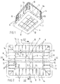
- in räumlicher Ansichtsdarstellung von unten einen kastenförmigen Behälter aus Kunststoff,
Figur 2- in größerem Maßstab die Unteransicht des kastenförmigen Behälters nach Fig. 1,
Figur 3- einen Schnitt entlang der Linie III-III durch den Bodenbereich des kastenförmigen Behälters nach Fig. 1,
Figur 4- einen Schnitt entlang der Linie IV-IV in Fig. 2 durch den Bodenbereich des Behälters nach Fig. 1 und
Figur 5- in Ansicht von unten eine gegenüber den Fig. 1 und 2 abgewandelte Ausführungsform des Bodenbereichs für einen kastenförmigen Behälter.
- Figure 1
- in a spatial view from below, a box-shaped container made of plastic,
- Figure 2
- on a larger scale the bottom view of the box-shaped container according to FIG. 1,
- Figure 3
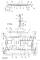
- 2 shows a section along the line III-III through the bottom region of the box-shaped container according to FIG. 1,
- Figure 4
- a section along the line IV-IV in Fig. 2 through the bottom region of the container of FIG. 1 and
- Figure 5
- in view from below a modified embodiment of the bottom region for a box-shaped container compared to FIGS. 1 and 2.
Der in Fig. 1 als Ausführungsbeispiel dargestellte kastenförmige Behälter 1 ist als Spritzgußformteil aus Kunststoff hergestellt. Er wird vornehmlich als Lager- und Transportkasten für den Gebrauch in Regalanlagen eingesetzt und eignet sich dabei in besonderem Maße für die Benutzung in solchen Regallagern, denen neben automatischen Beschickungs- und Entnahmeanlagen auch Förderstrecken zugeordnet sind.The box-shaped container 1 shown in Fig. 1 as an embodiment is made as an injection molded part made of plastic. It is primarily used as a storage and transport box for use in racking systems and is particularly suitable for use in racking systems which, in addition to automatic loading and unloading systems, are also assigned conveyor lines.
Schon hier sei erwähnt, daß es bei dem kastenförmigen Behälter 1 nicht maßgeblich darauf ankommt, welche Anordnung und Ausbildung dessen Längswände 2 und Querwände 3 haben, sondern vielmehr auf besondere Ausbildungsmaßnahmen im Bereich des Behälterbodens 4 sowie bezüglich weiterer Funktionsteile bzw. Ausbildungsmaßnahmen, die sich nach unten an diesen Behälterboden 4 anschließen.Already here it should be mentioned that the box-shaped container 1 does not significantly depend on the arrangement and design of its
Die nachfolgende Beschreibung betrifft daher zwar in erster Linie kastenförmige Behälter 1, bei denen sich an den Behälterboden 4 nach oben Längswände 2 und Querwände 3 einstückig anschließen. Die in diesem Zusammenhang erläuterten Ausbildungsmaßnahmen können jedoch ohne weiteres auch an Tablaren, Paletten oder ähnlichen Lager- und Transportmitteln vorkommen, die sich als Spritzguß-Formteile aus Kunststoff fertigen lassen.The following description therefore relates primarily to box-shaped containers 1, in which
Aus den Fig. 3 und 4 der Zeichnung geht hervor, daß der Behälterboden 4 des kastenförmigen Behälters 1 auf seiner Oberseite insgesamt eben ausgeführt ist, während er unterseitig durch längsverlaufende Versteifungsrippen 5 und querverlaufende Versteifungsrippen 6 stabilisiert ist, die einstückig mit ihm hergestellt sind.3 and 4 of the drawing it can be seen that the
Längs des äußeren Bodenrandes 7, der bspw. flanschartig über die äußeren Begrenzungsflächen der Längswände 2 und der Querwände 3 hinausragt, erstrecken sich in Richtung der Bodenebene verlaufende Flachstege 8, die durch jeweils quer zum Bodenrand 7 verlaufende, senkrechte Versteifungsrippen 9 im Abstand unterhalb der Bodenebene abgestützt sind. Die Flachstege 8 und die Versteifungsrippen 9 sind dabei einstückig mit dem kastenförmigen Behälter 1 bzw. dem Behälterboden 4 ausgeformt, wobei sich die Versteifungsrippen 9 jeweils im rechten Winkel an die äußeren Versteifungsrippen 5 und 6 anschließen, die sich parallel zu den Längswänden 2 und den Querwänden 3 des kastenförmigen Behälters erstrecken.Along the
Beim Ausführungsbeispiel eines kastenförmigen Behälters 1 nach den Fig. 1 und 2 bilden die Flachstege 8 miteinander gewissermaßen einen Rahmen, der so vorgesehen ist, daß die äußeren Begrenzungsränder 10 der Flachstege gegenüber dem Bodenrand 7 eine zurückversetzte Lage einnehmen, wie das deutlich aus Fig. 2 ersichtlich ist.In the embodiment of a box-shaped container 1 according to FIGS. 1 and 2, the
Die einwärts gerichteten Begrenzungsränder 11 der Flachstege 8 sind hingegen so gelegt, daß sie jeweils einen Abstand 12 von den parallel zu ihnen verlaufenden, unterseitig am Behälterboden 4 vorgesehenen, äußeren Versteifungsrippen 5 und 6 haben.The inward bounding
Die Flachstege 8 bilden miteinander die Standflächen des kastenförmigen Behälters 1 und sie grenzen zusammen mit den quergerichteten Verstifungsrippen 9 sowie der Unterseite des Behälterbodens 4 eine Vielzahl von taschenartigen Freiräumen 13 ein, die jeweils nebeneinanderliegend vorgesehen sind. Beim Ausführungsbeispiel nach den Fig. 1 bis 4 sind dabei taschenartige Freiräume 13, sowohl entlang der Längsbegrenzung des Bodenrandes 7 als auch entlang der Querbegrenzung desselben vorgesehen. Beim Ausführungsbeispiel nach Fig. 5 befinden sich hingegen solche taschenartig eingegrenzten Freiräume 13 nur im Bereich der Längsbegrenzung des Bodenrandes 7.The
Jeder taschenartig eingegrenzte Freiraum 13 ist an seinem äußeren Ende mit einer bodenrandseitigen Öffnung 14 versehen und weist darüber hinaus an seinem inneren Ende einen nach unten offenen Durchlaß 15 auf, welcher jeweils durch den Abstand 12 zwischen dem inneren Begrenzungsrand 11 und der benachbarten Versteifungsrippe 5 bzw. 6 des Bodens 4 vorhanden ist.Each pocket-like delimited
Durch die beidendig offene Ausführung der taschenartigen Freiräume 13 wird sichergestellt, daß sich diese in optimaler Weise mit Waschflüssigkeit durchspülen lassen und folglich darin festgesetzte Rückstände sicher entfernt werden können.The design of the pocket-like
In den Fig. 1, 3 und 4 der Zeichnung ist zu sehen, daß zumindest die parallel zu den einwärts gerichteten Begrenzungsrändern 11 der Flachstege 8 verlaufenden Versteifungsrippen 5 und 6 des Behälterbodens 4 gegenüber der Bodenunterseite eine Profilhöhe aufweisen, die etwas geringer ist als der lichte Abstand der Flachstege 8 von der Unterseite, des Behälterbodens 4. Diese Ausbildungsmaßnahme begünstigt das Durchspülen der taschenartigen Friräume 13 mit Waschflüssigkeit, weil der Austritt derselben aus den Durchlässen 15 erleichtert wird.1, 3 and 4 of the drawing it can be seen that at least the
Erkennbar ist aus den Fig. 3 und 4 der Zeichnung auch noch, daß die Flachstege 8 eine von ihrem äußeren Begrenzungsrand 10 zum inneren Begrenzungsrand 11 hin leicht ansteigende Neigungslage gegenüber der Bodenebene aufweisen. Dabei kann der Neigungswinkel zwischen 1 und 2o betragen, vorzugsweise bei 1,5o liegen. Diese Ausgestaltung trägt dazu bei, daß auch bei der Einlagerung schwerer Güter in den kastenförmigen Behälter 1 eine einwandfreie Standfläche für den kastenförmigen Behälter 1 erhalten bleibt. Der Behälterboden 4 kann sicha bestenfalls so weit durchbiegen, bis die Flachstege 8 in eine horizontale Lage gelangen. Es hat sich als günstig erwiesen, wenn der Abstand zwischen den quer zum Bodenrand 7 gerichteten Versteifungsrippen 9 kleiner bemessenwird als der übliche Teilungsabstand zwischen aufeinanderfolgenden Rollen einer als Transportmittel dienenden Rollenbahn. Aufgrund des geringen Abstandes zwischen den Versteifungsrippen 9 können sich dann die Flachstege 8 nicht in unerwünschter Weise quer zu ihrer Ebene durchbiegen. Ein ruhiger Lauf der kastenförmigen Behälter 1 über die als Transportmittel benutzten Rollenbahnen ist deshalb sichergestellt.It can also be seen from FIGS. 3 and 4 of the drawing that the
Aus den Fig. 2 und 4 der Zeichnung läßt sich auch noch entnehmen, daß die Breite der Flachstege 8 vorzugsweise größer bemessen wird, als der Abstand zwischen den Versteifungsrippen 9. Als vorteilhaft hat es sich erwiesen, wenn die Breite der Flachstege 8 mindestens doppelt so groß ausgeführt wird, wie der Abstand zwischen zwei benachbarten Versteifungsrippen 9.From FIGS. 2 and 4 of the drawing it can also be seen that the width of the
Während aus den Fig. 2 und 5 der Zeichnung deutlich hervorgeht, daß die Boden-Versteifungsrippen 5 und 6 im Bereich des Bodenmittelfeldes eines sich gitterartig kreuzende Anordnung haben, geht aus den Fig. 1, 3 und 4 noch hervor, daß sie auch eine sich in Richtung zur Bodenmitte hin jeweils vermindernde Profilhöhe aufweisen können.2 and 5 of the drawing clearly show that the
Im Falle des Ausführungsbeispiels nach Fig. 2 ist zwischen den sich gitterartig kreuzenden Versteifungsrippen 5 und 6 auch noch ein sich in Richtung zur Bodenmitte hin verringernder Abstand vorgesehen.In the case of the exemplary embodiment according to FIG. 2, a spacing which decreases towards the center of the floor is also provided between the stiffening
Beim Ausführungsbeispiel nach Fig. 5 is die Anordnung der Boden-Versteifungsrippen 5 und 6 hingegen so getroffen, daß sich der Abstand zwischen den querverlaufenden Versteifungsrippen 6 in Richtung zur Bodenmitte hin verringert, während er sich im Falle der längsverlaufenden Boden-Versteifungsrippen 5 vergrößert.In the exemplary embodiment according to FIG. 5, the arrangement of the
In vielen Fällen kann es sich als vorteilhaft erweisen, die als Standfläche für den kastenförmigen Behälter 1 dienende Unterseite der Flachstege 8 mit Aufrauhungen, z.B. Riffelungen oder dergleichen, zu versehen. Hierdurch kann einerseits eine bessere Haftung auf den Unterztützungsflächen für die kastenförmigen Behälter 1 herbeigeführt werden. Andererseits hat sich aber auch gezeigt, daß diese Aufrauhungen zu einer Laufrüheverbesserung der kastenförmigen Behälter 1 auf de Förderstrecken von Transportmitteln, bspw. auf Rollenbahnen, führen, indem die entstehenden Laufgeräusche verringert werden.In many cases it can prove to be advantageous to roughen the underside of the
Abschließend sei noch erwähnt, daß sich ein kastenförmiger Behälter 1 der aus Fig. 5 ersichtlichen Bauart in besondere vorteilhafter Art und Weise dort zur Benutzung eignet, wo Regalanlagen mit Bechickungs- und Entnahmevorrichtungen zusammenarbeiten, die nach dem Prinzip der sogenannten Ziehtechnik arbeiten.Finally, it should also be mentioned that a box-shaped container 1 of the type shown in FIG. 5 is particularly suitable for use where rack systems work together with loading and unloading devices which operate on the principle of the so-called drawing technique.
Claims (10)
dadurch gekennzeichnet,
daß die einwärts grichteten Begrenzungsränder (11) der die Standflächen bildenden Flachstege (8) einen Abstand (12) von parallel zu ihnen verlaufenden, unterseitigen Boden-Versteifungsrippen (5 und 6) haben und dort nach unten offene Durchlässe (15) in den taschenartig eingegrenzten Freiräumen (13) ausbilden.Box-shaped container made of plastic, in particular storage and transport box, in which a flat upper surface is stabilized on the underside by stiffening ribs, and in which flat webs extend along the bottom edge in the direction of the bottom plane and are spaced apart by stiffening ribs extending transversely to the bottom edge are supported below the floor level and form the standing surfaces of the container, the free spaces delimited pocket-like between the bottom underside, the flat web top and the transverse stiffening ribs being designed to be completely open at the bottom edge,
characterized,
that the inwardly directed boundary edges (11) of the flat webs (8) forming the standing surfaces have a distance (12) from parallel to them, underside bottom stiffening ribs (5 and 6) and there open openings (15) delimited in the pocket-like manner Form free space (13).
dadurch gekennzeichnet,
daß die parallel zu den einwärts gerichteten Begrenzungsrändern (11) der Flachstege (8) verlaufenden Versteifungsrippen (5 und 6) gegenüber der Bodenunterseite eine Profilhöhe aufweisen, die geringer ist, als der lichte Abstand der Flachstege (8) von der Bodenunterseite.Box-shaped container according to claim 1,
characterized,
that the stiffening ribs (5 and 6) running parallel to the inward bounding edges (11) of the flat webs (8) have a profile height with respect to the underside of the floor which is less than the clear distance between the flat webs (8) and the underside of the floor.
der Ansprüche 1 und 2,
dadurch gekennzeichnet,
daß die Flachstege (8) eine von ihrem äußeren Begrenzungsrand (10) zum inneren Begrenzungsrand (11) hin leicht ansteigende Neigungslage gegenüber der Bodenebene aufweisen.Box-shaped container after one
of claims 1 and 2,
characterized,
that the flat webs (8) have a slightly increasing inclination from their outer boundary edge (10) to the inner boundary edge (11) towards the ground plane.
der Ansprüche 1 bis 3,
dadurch gekennzeichnet,
daß der Abstand zwischen den quer zum Bodenrand (7) gerichteten Versteifungsrippen (9) kleiner als der Teilungsabstand zwischen aufeinanderfolgenden Rollen einer als Transportmittel dienenden Rollenbahn ausgeführt ist.Box-shaped container after one
of claims 1 to 3,
characterized,
that the distance between the reinforcing ribs (9) directed transversely to the bottom edge (7) is smaller than the spacing between successive rollers of a roller conveyor serving as a means of transport.
der Ansprüche 1 bis 4,
dadurch gekennzeichnet,
daß die Breite der Flachstege (8) größer als der Abstand zwischen den Versteifungsrippen (9) bemessen ist, vorzugsweise mindestens dem Doppelten dieses Abstandes entspricht.Box-shaped container after one
of claims 1 to 4,
characterized,
that the width of the flat webs (8) is larger than the distance between the stiffening ribs (9), preferably corresponds to at least twice this distance.
der Ansprüche 1 bis 5,
dadurch gekennzeichnet,
daß die Boden-Versteifungsrippen (5 und 6) im Bodenmittelfeld mit sich gitterartig kreuzender Anordnung vorgesehen sind und dabei eine sich in Richtung zur Bodenmitte hin vermindernde Profilhöhe aufweisen (Fig. 3 und 4).Box-shaped container after one
of claims 1 to 5,
characterized,
that the floor stiffening ribs (5 and 6) are provided in the floor middle field with a grid-like crossing arrangement and have a decreasing profile height towards the floor center (Fig. 3 and 4).
der Ansprüche 1 bis 6,
dadurch gekennzeichnet,
daß zwischen den sich gitterartig kreuzenden Versteifungsrippen (5 und 6) ein sich in Richtung zur Bodenmitte hin verringernder Abstand vorgesehen ist (Fig. 2).Box-shaped container after one
of claims 1 to 6,
characterized,
that between the grid-like stiffening ribs (5 and 6) there is a decreasing distance towards the center of the floor (Fig. 2).
der Ansprüche 1 bis 7,
dadurch gekennzeichnet,
daß sich die Flachstege rahmenartig entlang der Längs- und Querränder (7) des Bodens (4) erstrecken (Fig. 1 und 2).Box-shaped container after one
of claims 1 to 7,
characterized,
that the flat webs extend frame-like along the longitudinal and transverse edges (7) of the bottom (4) (Fig. 1 and 2).
der Ansprüche 1 bis 7,
dadurch gekennzeichnet,
daß sich die Flachstege (8) lediglich entlang der Längsränder (7) des Bodens (4) erstrecken (Fig. 5).Box-shaped container after one
of claims 1 to 7,
characterized by
that the flat webs (8) only extend along the longitudinal edges (7) of the bottom (4) (Fig. 5).
der Ansprüche 1 bis 9,
dadurch gekennzeichnet,
daß die Unterseite der Flachstege (8) mit Aufrauhungen, z.B. Riffelungen, versehen ist.Box-shaped container after one
of claims 1 to 9,
characterized,
that the underside of the flat webs (8) is roughened, for example corrugations.
Applications Claiming Priority (2)
| Application Number | Priority Date | Filing Date | Title |
|---|---|---|---|
| DE4105527A DE4105527A1 (en) | 1991-02-22 | 1991-02-22 | BOXED PLASTIC CONTAINER |
| DE4105527 | 1991-02-22 |
Publications (3)
| Publication Number | Publication Date |
|---|---|
| EP0499852A2 true EP0499852A2 (en) | 1992-08-26 |
| EP0499852A3 EP0499852A3 (en) | 1993-02-24 |
| EP0499852B1 EP0499852B1 (en) | 1996-05-01 |
Family
ID=6425624
Family Applications (1)
| Application Number | Title | Priority Date | Filing Date |
|---|---|---|---|
| EP92101523A Expired - Lifetime EP0499852B1 (en) | 1991-02-22 | 1992-01-30 | Plastic container in the form of a crate |
Country Status (5)
| Country | Link |
|---|---|
| US (1) | US5397022A (en) |
| EP (1) | EP0499852B1 (en) |
| AT (1) | ATE137461T1 (en) |
| CA (1) | CA2061677A1 (en) |
| DE (2) | DE4105527A1 (en) |
Cited By (2)
| Publication number | Priority date | Publication date | Assignee | Title |
|---|---|---|---|---|
| EP0662424A1 (en) * | 1994-01-08 | 1995-07-12 | Stucki Kunststoffwerk und Werkzeugbau GmbH. | Plastic storage and transport means |
| EP2112076A1 (en) * | 2008-04-27 | 2009-10-28 | Linpac Allibert GmbH | Integrated plastic transport box |
Families Citing this family (17)
| Publication number | Priority date | Publication date | Assignee | Title |
|---|---|---|---|---|
| DE4338061C2 (en) * | 1993-11-08 | 2002-08-22 | Schaefer Gmbh Fritz | Box-shaped container made of plastic |
| DE4338063C2 (en) * | 1993-11-08 | 2002-08-01 | Schaefer Gmbh Fritz | Box-shaped container made of plastic |
| US5735431A (en) * | 1996-08-19 | 1998-04-07 | Allibert-Contico, L.L.C. | Bin having an arched beam bottom |
| DE19844014C1 (en) * | 1998-09-25 | 2000-01-20 | Linpac Stucki Kunststoffverarb | Integral moulded plastics cargo container |
| DE19844015B4 (en) | 1998-09-25 | 2004-06-17 | Linpac Stucki Kunststoffverarbeitung Gmbh | Transport box made in one piece from plastic |
| US8348088B2 (en) * | 2007-06-22 | 2013-01-08 | Rehrig Pacific Company | Container with reinforced base |
| US9301520B2 (en) * | 2007-12-21 | 2016-04-05 | Sartorius Stedim North America Inc. | Systems and methods for freezing, storing and thawing biopharmaceutical materials |
| US8529120B2 (en) * | 2008-03-18 | 2013-09-10 | Vita-Mix Corporation | Blender container and cover |
| US20140097186A1 (en) * | 2012-10-08 | 2014-04-10 | Michael D. Stolzman | Crate |
| EP4316324A3 (en) | 2013-03-15 | 2024-03-13 | Vita-Mix Management Corporation | Powered blending container |
| CN104495095B (en) * | 2014-11-12 | 2017-01-18 | 深圳市华星光电技术有限公司 | Injection-molded packing case for liquid crystal display panels |
| USD830124S1 (en) | 2016-03-04 | 2018-10-09 | Vita-Mix Management Corporation | Container |
| USD839670S1 (en) | 2017-02-16 | 2019-02-05 | Vita-Mix Management Corporation | Blending container |
| USD842566S1 (en) | 2017-06-15 | 2019-03-05 | Vita-Mix Management Corporation | Container scraper |
| ES2911802T3 (en) * | 2019-05-07 | 2022-05-20 | Schoeller Allibert Gmbh | Container with support plate with projections |
| DE102020128601B3 (en) * | 2020-10-30 | 2021-12-02 | Gebhardt Fördertechnik GmbH | Plastic container |
| CN113550164B (en) * | 2021-07-21 | 2022-08-19 | 山东昌腾包装科技有限公司 | Environment-friendly paper-plastic packaging box and processing method thereof |
Citations (4)
| Publication number | Priority date | Publication date | Assignee | Title |
|---|---|---|---|---|
| GB2076366A (en) * | 1980-05-20 | 1981-12-02 | Utz Ag Georg | Stackable crates |
| DE8137907U1 (en) * | 1981-12-28 | 1982-04-15 | Fritz Schäfer GmbH, 5908 Neunkirchen | Box-shaped containers, especially storage and transport boxes |
| DE8903430U1 (en) * | 1989-03-07 | 1989-07-20 | Stucki Kunststoffwerk Und Werkzeugbau Gmbh, 4902 Bad Salzuflen, De | |
| DE9002339U1 (en) * | 1990-02-28 | 1990-06-13 | Stucki Kunststoffwerk Und Werkzeugbau Gmbh, 4902 Bad Salzuflen, De |
Family Cites Families (7)
| Publication number | Priority date | Publication date | Assignee | Title |
|---|---|---|---|---|
| US3985258A (en) * | 1975-10-01 | 1976-10-12 | Quigley Patrick C | Knock-down plastic container for produce and the like |
| US4000827A (en) * | 1976-01-09 | 1977-01-04 | Anthony Emery | Produce container |
| GR64982B (en) * | 1977-10-04 | 1980-06-11 | Palbox Spa | Reception(receiver)made of inflated thermoplastic material for the carrying out and storage of goods in bulk,for example agricultural products |
| US4375265A (en) * | 1978-07-21 | 1983-03-01 | Wetering Gerrit Van De | One piece molded pallet-container |
| GB2197294B (en) * | 1986-11-17 | 1990-04-04 | Boyce Graham John | A bin designed to be lifted by a fork lift truck. |
| US4775068A (en) * | 1988-01-11 | 1988-10-04 | Xytec Plastics, Inc. | Collapsible container with removable access panel |
| DE4006188C1 (en) * | 1990-02-28 | 1991-07-25 | Stucki Kunststoffwerk Und Werkzeugbau Gmbh, 4902 Bad Salzuflen, De | Plastic transport crate with ribbed base - has false bottom with upwards inclined section at crate centre facing edge |
-
1991
- 1991-02-22 DE DE4105527A patent/DE4105527A1/en active Granted
-
1992
- 1992-01-30 EP EP92101523A patent/EP0499852B1/en not_active Expired - Lifetime
- 1992-01-30 AT AT92101523T patent/ATE137461T1/en not_active IP Right Cessation
- 1992-01-30 DE DE59206146T patent/DE59206146D1/en not_active Expired - Lifetime
- 1992-02-21 CA CA002061677A patent/CA2061677A1/en not_active Abandoned
-
1993
- 1993-11-23 US US08/157,355 patent/US5397022A/en not_active Expired - Fee Related
Patent Citations (4)
| Publication number | Priority date | Publication date | Assignee | Title |
|---|---|---|---|---|
| GB2076366A (en) * | 1980-05-20 | 1981-12-02 | Utz Ag Georg | Stackable crates |
| DE8137907U1 (en) * | 1981-12-28 | 1982-04-15 | Fritz Schäfer GmbH, 5908 Neunkirchen | Box-shaped containers, especially storage and transport boxes |
| DE8903430U1 (en) * | 1989-03-07 | 1989-07-20 | Stucki Kunststoffwerk Und Werkzeugbau Gmbh, 4902 Bad Salzuflen, De | |
| DE9002339U1 (en) * | 1990-02-28 | 1990-06-13 | Stucki Kunststoffwerk Und Werkzeugbau Gmbh, 4902 Bad Salzuflen, De |
Cited By (2)
| Publication number | Priority date | Publication date | Assignee | Title |
|---|---|---|---|---|
| EP0662424A1 (en) * | 1994-01-08 | 1995-07-12 | Stucki Kunststoffwerk und Werkzeugbau GmbH. | Plastic storage and transport means |
| EP2112076A1 (en) * | 2008-04-27 | 2009-10-28 | Linpac Allibert GmbH | Integrated plastic transport box |
Also Published As
| Publication number | Publication date |
|---|---|
| ATE137461T1 (en) | 1996-05-15 |
| EP0499852B1 (en) | 1996-05-01 |
| DE4105527C2 (en) | 1993-09-23 |
| EP0499852A3 (en) | 1993-02-24 |
| CA2061677A1 (en) | 1992-08-23 |
| DE4105527A1 (en) | 1992-08-27 |
| DE59206146D1 (en) | 1996-06-05 |
| US5397022A (en) | 1995-03-14 |
Similar Documents
| Publication | Publication Date | Title |
|---|---|---|
| EP0499852B1 (en) | Plastic container in the form of a crate | |
| EP0536462A1 (en) | Parallelepipedic plastic container | |
| DE2000543A1 (en) | Packaging container | |
| DE3709190C2 (en) | ||
| DE4338063C2 (en) | Box-shaped container made of plastic | |
| DE3909022C3 (en) | Storage and transport means made of plastic | |
| WO1992008650A1 (en) | Plastic load carrier and tool for its production | |
| DE102007033147B4 (en) | Stackable roll container | |
| EP1110869B1 (en) | Plastic container in the form of a crate | |
| DE19628373C2 (en) | Transport container made of plastic, which can be stacked according to the rotary stacking principle | |
| EP0386313B2 (en) | Storage and transport means made of plastics | |
| DE2805880A1 (en) | SPROCKET | |
| DE8137907U1 (en) | Box-shaped containers, especially storage and transport boxes | |
| DE6912976U (en) | DEVICE FOR TRANSPORTING AND STACKING TABLE OR KITCHEN UTENSILS | |
| EP0989063B1 (en) | One-piece plastic transport crate | |
| DE19844014C1 (en) | Integral moulded plastics cargo container | |
| DE7622928U1 (en) | Stacking pallet for transporting dirt-releasing goods | |
| EP2338799B1 (en) | Thermoplastic container | |
| DE2002073A1 (en) | Fruit dough | |
| EP0331989B1 (en) | Storage and/or transport box | |
| DE2602489C3 (en) | Plastic bottle crate | |
| EP3409605A1 (en) | Box, in particular for storing and/or transporting dishes | |
| DE1180304B (en) | Storage and transport containers | |
| DE4338061C2 (en) | Box-shaped container made of plastic | |
| DE2126773B2 (en) | Fish crate |
Legal Events
| Date | Code | Title | Description |
|---|---|---|---|
| PUAI | Public reference made under article 153(3) epc to a published international application that has entered the european phase |
Free format text: ORIGINAL CODE: 0009012 |
|
| 17P | Request for examination filed |
Effective date: 19920211 |
|
| AK | Designated contracting states |
Kind code of ref document: A2 Designated state(s): AT BE CH DE DK ES FR GB GR IT LI LU NL SE |
|
| PUAL | Search report despatched |
Free format text: ORIGINAL CODE: 0009013 |
|
| AK | Designated contracting states |
Kind code of ref document: A3 Designated state(s): AT BE CH DE DK ES FR GB GR IT LI LU NL SE |
|
| 17Q | First examination report despatched |
Effective date: 19950706 |
|
| GRAA | (expected) grant |
Free format text: ORIGINAL CODE: 0009210 |
|
| AK | Designated contracting states |
Kind code of ref document: B1 Designated state(s): AT BE CH DE DK ES FR GB GR IT LI LU NL SE |
|
| PG25 | Lapsed in a contracting state [announced via postgrant information from national office to epo] |
Ref country code: NL Free format text: LAPSE BECAUSE OF FAILURE TO SUBMIT A TRANSLATION OF THE DESCRIPTION OR TO PAY THE FEE WITHIN THE PRESCRIBED TIME-LIMIT Effective date: 19960501 Ref country code: IT Free format text: LAPSE BECAUSE OF FAILURE TO SUBMIT A TRANSLATION OF THE DESCRIPTION OR TO PAY THE FEE WITHIN THE PRESCRIBED TIME-LIMIT;WARNING: LAPSES OF ITALIAN PATENTS WITH EFFECTIVE DATE BEFORE 2007 MAY HAVE OCCURRED AT ANY TIME BEFORE 2007. THE CORRECT EFFECTIVE DATE MAY BE DIFFERENT FROM THE ONE RECORDED. Effective date: 19960501 Ref country code: GR Free format text: LAPSE BECAUSE OF FAILURE TO SUBMIT A TRANSLATION OF THE DESCRIPTION OR TO PAY THE FEE WITHIN THE PRESCRIBED TIME-LIMIT Effective date: 19960501 Ref country code: BE Effective date: 19960501 Ref country code: GB Effective date: 19960501 Ref country code: DK Effective date: 19960501 Ref country code: FR Effective date: 19960501 Ref country code: ES Free format text: THE PATENT HAS BEEN ANNULLED BY A DECISION OF A NATIONAL AUTHORITY Effective date: 19960501 |
|
| REF | Corresponds to: |
Ref document number: 137461 Country of ref document: AT Date of ref document: 19960515 Kind code of ref document: T |
|
| REF | Corresponds to: |
Ref document number: 59206146 Country of ref document: DE Date of ref document: 19960605 |
|
| PG25 | Lapsed in a contracting state [announced via postgrant information from national office to epo] |
Ref country code: SE Effective date: 19960801 |
|
| GRAH | Despatch of communication of intention to grant a patent |
Free format text: ORIGINAL CODE: EPIDOS IGRA |
|
| EN | Fr: translation not filed | ||
| NLV1 | Nl: lapsed or annulled due to failure to fulfill the requirements of art. 29p and 29m of the patents act | ||
| GBV | Gb: ep patent (uk) treated as always having been void in accordance with gb section 77(7)/1977 [no translation filed] |
Effective date: 19960501 |
|
| PLAV | Examination of admissibility of opposition |
Free format text: ORIGINAL CODE: EPIDOS OPEX |
|
| PLBQ | Unpublished change to opponent data |
Free format text: ORIGINAL CODE: EPIDOS OPPO |
|
| PG25 | Lapsed in a contracting state [announced via postgrant information from national office to epo] |
Ref country code: AT Free format text: LAPSE BECAUSE OF NON-PAYMENT OF DUE FEES Effective date: 19970130 |
|
| PG25 | Lapsed in a contracting state [announced via postgrant information from national office to epo] |
Ref country code: LU Free format text: LAPSE BECAUSE OF NON-PAYMENT OF DUE FEES Effective date: 19970131 Ref country code: LI Effective date: 19970131 Ref country code: CH Effective date: 19970131 |
|
| PLBI | Opposition filed |
Free format text: ORIGINAL CODE: 0009260 |
|
| PLAV | Examination of admissibility of opposition |
Free format text: ORIGINAL CODE: EPIDOS OPEX |
|
| PLBF | Reply of patent proprietor to notice(s) of opposition |
Free format text: ORIGINAL CODE: EPIDOS OBSO |
|
| 26 | Opposition filed |
Opponent name: STUCKI KUNSTSTOFFWERK UND WERKZEUGBAU GMBH Effective date: 19970123 |
|
| PLBF | Reply of patent proprietor to notice(s) of opposition |
Free format text: ORIGINAL CODE: EPIDOS OBSO |
|
| REG | Reference to a national code |
Ref country code: CH Ref legal event code: PL |
|
| PLBF | Reply of patent proprietor to notice(s) of opposition |
Free format text: ORIGINAL CODE: EPIDOS OBSO |
|
| PLBO | Opposition rejected |
Free format text: ORIGINAL CODE: EPIDOS REJO |
|
| APAC | Appeal dossier modified |
Free format text: ORIGINAL CODE: EPIDOS NOAPO |
|
| APAE | Appeal reference modified |
Free format text: ORIGINAL CODE: EPIDOS REFNO |
|
| APAC | Appeal dossier modified |
Free format text: ORIGINAL CODE: EPIDOS NOAPO |
|
| APAC | Appeal dossier modified |
Free format text: ORIGINAL CODE: EPIDOS NOAPO |
|
| PLBO | Opposition rejected |
Free format text: ORIGINAL CODE: EPIDOS REJO |
|
| PLBN | Opposition rejected |
Free format text: ORIGINAL CODE: 0009273 |
|
| STAA | Information on the status of an ep patent application or granted ep patent |
Free format text: STATUS: OPPOSITION REJECTED |
|
| 27O | Opposition rejected |
Effective date: 20000618 |
|
| APAH | Appeal reference modified |
Free format text: ORIGINAL CODE: EPIDOSCREFNO |
|
| PGFP | Annual fee paid to national office [announced via postgrant information from national office to epo] |
Ref country code: DE Payment date: 20100121 Year of fee payment: 19 |
|
| REG | Reference to a national code |
Ref country code: DE Ref legal event code: R119 Ref document number: 59206146 Country of ref document: DE Effective date: 20110802 |
|
| PG25 | Lapsed in a contracting state [announced via postgrant information from national office to epo] |
Ref country code: DE Free format text: LAPSE BECAUSE OF NON-PAYMENT OF DUE FEES Effective date: 20110802 |