EP0499524A1 - Asymmetrical gas feeding nozzle for coating a glass ribbon by pyrolysis of a gas mixture - Google Patents
Asymmetrical gas feeding nozzle for coating a glass ribbon by pyrolysis of a gas mixture Download PDFInfo
- Publication number
- EP0499524A1 EP0499524A1 EP92400344A EP92400344A EP0499524A1 EP 0499524 A1 EP0499524 A1 EP 0499524A1 EP 92400344 A EP92400344 A EP 92400344A EP 92400344 A EP92400344 A EP 92400344A EP 0499524 A1 EP0499524 A1 EP 0499524A1
- Authority
- EP
- European Patent Office
- Prior art keywords
- central
- glass ribbon
- downstream
- upstream
- gas
- Prior art date
- Legal status (The legal status is an assumption and is not a legal conclusion. Google has not performed a legal analysis and makes no representation as to the accuracy of the status listed.)
- Granted
Links
Images
Classifications
-
- C—CHEMISTRY; METALLURGY
- C03—GLASS; MINERAL OR SLAG WOOL
- C03C—CHEMICAL COMPOSITION OF GLASSES, GLAZES OR VITREOUS ENAMELS; SURFACE TREATMENT OF GLASS; SURFACE TREATMENT OF FIBRES OR FILAMENTS MADE FROM GLASS, MINERALS OR SLAGS; JOINING GLASS TO GLASS OR OTHER MATERIALS
- C03C17/00—Surface treatment of glass, not in the form of fibres or filaments, by coating
- C03C17/001—General methods for coating; Devices therefor
- C03C17/002—General methods for coating; Devices therefor for flat glass, e.g. float glass
Landscapes
- Chemical & Material Sciences (AREA)
- Life Sciences & Earth Sciences (AREA)
- Engineering & Computer Science (AREA)
- Chemical Kinetics & Catalysis (AREA)
- General Chemical & Material Sciences (AREA)
- Geochemistry & Mineralogy (AREA)
- Materials Engineering (AREA)
- Organic Chemistry (AREA)
- Surface Treatment Of Glass (AREA)
- Chemical Vapour Deposition (AREA)
Abstract
Description
La présente invention concerne une buse équipant un appareil pour la formation, sur un ruban de verre chaud, d'une couche de revêtement obtenue à partir de gaz, tels que des gaz de métaux carbonyles ou de composés métalliques hydrogénés volatils pouvant se décomposer en touchant le verre chaud, par exemple les silanes et, notamment, le monosilane.The present invention relates to a nozzle fitted with an apparatus for forming, on a strip of hot glass, a coating layer obtained from gases, such as carbonyl metal gases or volatile hydrogenated metal compounds which can decompose by touching hot glass, for example silanes and, in particular, monosilane.
Par le brevet FR 2 314 152, on connaît une buse de ce type dans laquelle on envoie sur la face à revêtir du ruban de verre en cours de déplacement, un gaz de revêtement émis par un distributeur qui s'étend transversalement au ruban et à la direction de mouvement de ce dernier, de façon que le gaz s'écoule parallèlement à la surface du verre, en régime laminaire et avec un débit uniforme sur toute la largeur du ruban.From patent FR 2 314 152, there is known a nozzle of this type in which a coating gas emitted by a distributor which extends transversely to the ribbon and to the glass is sent on the face to be coated with glass ribbon during movement. the direction of movement of the latter, so that the gas flows parallel to the surface of the glass, in laminar mode and with a uniform flow over the entire width of the strip.
A cet effet, la buse comprend un dispositif d'injection du gaz, un bloc profilé central, un talon profilé latéral amont et un talon profilé latéral aval disposés de part et d'autre du bloc central de manière à offrir au gaz arrivant du dispositif d'injection un trajet d'écoulement le long d'un canal de guidage en U qui s'étend entre le talon latéral amont et le bloc central, entre la face inférieure du bloc central et le ruban de verre, et entre le bloc central et le talon aval et un dispositif d'aspiration du gaz ménagé à la sortie du canal entre le bloc central et le talon aval.To this end, the nozzle comprises a gas injection device, a central profiled block, an upstream lateral profiled heel and a downstream lateral profiled heel arranged on either side of the central block so as to provide gas arriving from the device. injection a flow path along a U-shaped guide channel which extends between the upstream lateral heel and the central block, between the underside of the central block and the glass ribbon, and between the central block and the downstream heel and a gas suction device formed at the outlet of the channel between the central block and the downstream heel.
Les termes amont, central et aval se réfèrent au sens de mouvement du ruban de verre.The terms upstream, central and downstream refer to the direction of movement of the glass ribbon.
Le talon amont et le talon aval sont pourvus de faces inférieures plates qui s'étendent parallèlement à la surface du verre et à faible distance de cette surface (environ 1 mm), afin de minimiser les fuites de gaz apparaissant entre ces faces et le verre.The upstream heel and the downstream heel are provided with flat lower faces which extend parallel to the surface of the glass and at a short distance from this surface (approximately 1 mm), in order to minimize the gas leaks appearing between these faces and the glass. .
Cette buse fonctionne correctement lorsqu'on veut déposer sur le ruban de verre un revêtement de faible épaisseur, par exemple inférieur à 60 nanomètres et/ou mettant on jeu des débits faibles de gaz, par exemple de l'ordre de 100 l/mn sur une buse d'environ 3,30 m de large. En effet, pour ces épaisseurs, le courant gazeux se trouvant dans la partie horizontale du canal s'écoule à une vitesse inférieure à celle du ruban. Ce courant est, de ce fait, entièrement entraîné par le ruban de verre vers l'aval, de sorte qu'il ne se produit aucune fuite de gaz ni d'encrassement sur le talon amont. De même, les fuites pouvant se produire sous le talon aval sont suffisamment faibles, pour que les périodes de production soient longues par rapport aux périodes de nettoyage. La perte de verre est donc relativement limitée.This nozzle functions correctly when it is desired to deposit on the glass ribbon a coating of thin thickness, for example less than 60 nanometers and / or bringing into play low gas flow rates, for example of the order of 100 l / min on a nozzle about 3.30 m wide. In fact, for these thicknesses, the gas stream located in the horizontal part of the channel flows at a speed lower than that of the strip. This current is, therefore, entirely driven by the glass ribbon downstream, so that there is no gas leakage or fouling on the upstream heel. Likewise, the leaks that may occur under the downstream heel are sufficiently low, so that the production periods are long compared to the cleaning periods. The loss of glass is therefore relatively limited.
Par contre, lorsqu'on veut déposer sur le verre une couche de revêtement plus épaisse, par exemple de l'ordre de 80 nanomètres, et/ou mettant en jeu des débits gazeux plus importants, par exemple de l'ordre de 400 l/mn au moins sur une buse d'environ 3,30 m de large, la vitesse de passage du gaz peut devenir nettement supérieure à celle du ruban de verre. Mais, cette augmentation de la vitesse entraîne les inconvénients suivants :
- ■ la longueur de la partie horizontale du canal de section en U doit être allongée dans la même proportion que les vitesses, afin que le temps de contact du gaz avec le verre soit suffisant d'une part, pour assurer sa décomposition et, d'autre part, pour obtenir l'épaisseur de couche souhaitée,
- ■ la vitesse du gaz étant supérieure à celle du ruban de verre, les fuites sous le talon aval deviennent importantes et des fuites sous le talon amont apparaissent. Les faces inférieures de ces talons s'encrassent rapidement par dépôt de matière de revêtement, ce qui crée des veines gazeuses où les vitesses d'écoulement sont plus fortes, et se traduit par un dépôt non homogène dans le sens transversal du ruban de verre. Celui-ci se trouve alors recouvert d'une couche de matière dont l'épaisseur, donc la couleur, la réflexion lumineuse et la transmission lumineuse, varient transversalement,
- ■ lorsque l'encrassement devient trop important, des particules de revêtement peuvent toucher le verre et y laisser des marques,
- ■ le dépôt qui s'accroît au cours du temps nécessite un nettoyage périodique de la buse, entraînant de ce fait une perte de verre, puisque l'intallation de production continue à débiter pendant le nettoyage,
- ■ les fuites de gaz non récupérées polluent l'atmosphère du bain de flottage du verre dans la mesure où une telle buse est installée à l'intérieur d'une enceinte float pour la fabrication du verre.
- ■ the length of the horizontal part of the U-shaped channel section must be lengthened in the same proportion as the speeds, so that the contact time of the gas with the glass is sufficient on the one hand, to ensure its decomposition and, on the other hand, to obtain the desired layer thickness,
- ■ the gas speed being higher than that of the glass ribbon, the leaks under the downstream heel become significant and leaks under the upstream heel appear. The undersides of these heels quickly become clogged by depositing coating material, which creates gas streams where the flow velocities are higher, and results in a non-homogeneous deposit in the transverse direction of the glass ribbon. This is then covered with a layer of material whose thickness, therefore color, light reflection and light transmission, vary transversely,
- ■ when the fouling becomes too great, particles of coating can touch the glass and leave marks on it,
- The deposit which increases over time necessitates periodic cleaning of the nozzle, thereby causing loss of glass, since the production installation continues to flow during cleaning,
- ■ leaks of unrecovered gas pollute the atmosphere of the glass float bath insofar as such a nozzle is installed inside a float enclosure for the manufacture of glass.
La présente invention a pour but de remédier à tous ces inconvénients en proposant une buse pouvant déposer sur le ruban de verre une couche relativement épaisse et/ou mettant en jeu des débits élevés de gaz.The object of the present invention is to remedy all these drawbacks by proposing a nozzle capable of depositing on the glass ribbon a relatively thick layer and / or involving high gas flow rates.
La buse selon l'invention se caractérise en ce qu'elle comprend :
- ■ un premier et un second blocs profilés centraux définissant entre eux un passage central d'injection, transversal par rapport au ruban de verre, lesdits blocs centraux formant avec le ruban de verre deux passages d'épaisseur constante entre lesquels le gaz qui arrive du passage central d'injection se partage en deux courants laminaires, parallèles au ruban de verre et se dirigeant l'un vers l'amont et l'autre vers l'aval,
- ■ un talon profilé amont et un talon profilé aval montés respectivement en amont du premier bloc central et en aval du second bloc central, et qui définissent avec ces derniers un passage d'aspiration amont et un passage d'aspiration aval, l'un au moins desdits talons amont et aval étant, de préférence, pourvus d'une face inférieure surélevée par rapport au ruban de verre.
- A first and a second central profiled block defining between them a central injection passage, transverse with respect to the glass ribbon, said blocks central forming with the glass ribbon two passages of constant thickness between which the gas arriving from the central injection passage is divided into two laminar streams, parallel to the glass ribbon and directed one upstream and other downstream,
- ■ an upstream profiled heel and a downstream profiled heel mounted respectively upstream of the first central block and downstream of the second central block, and which define with the latter an upstream suction passage and a downstream suction passage, one at less of said upstream and downstream heels being preferably provided with a lower face raised relative to the glass ribbon.
La buse comprend, en outre, un dispositif d'injection de gaz monté à l'entrée du passage central d'injection et deux dispositifs d'aspiration de gaz montés respectivement à la sortie desdits passages d'aspiration amont et aval.The nozzle further comprises a gas injection device mounted at the inlet of the central injection passage and two gas suction devices mounted respectively at the outlet of said upstream and downstream suction passages.
Lorsque les talons amont et aval sont surélevés par rapport au ruban de verre, l'éventuel encrassement de leur face inférieure n'est pas perturbant. En particulier, il n'entraîne ni la modification d'écoulements gazeux susceptibles de conduire à des irrégularités du revêtement, ni la formation de marques faites sur le verre lorsqu'il devient trop important.When the upstream and downstream heels are raised relative to the glass ribbon, the possible fouling of their underside is not disturbing. In particular, it neither causes the modification of gas flows liable to lead to irregularities in the coating, nor the formation of marks made on the glass when it becomes too large.
De plus, bien que lesdits talons amont et aval soient à grande distance du ruban de verre, il ne se produit aucune fuite de gaz vers l'amont et vers l'aval car les deux courants gazeux qui s'écoulent sur le ruban de verre vers l'amont et l'aval sont respectivement bloqués par des contre-courants de gaz ambiant qui sont aspirés en même temps que lesdits courants gazeux.In addition, although said upstream and downstream heels are at a great distance from the glass ribbon, there is no gas leakage upstream and downstream because the two gas streams which flow on the glass ribbon upstream and downstream are respectively blocked by ambient gas countercurrents which are sucked in at the same time as said gas streams.
Le ruban de verre étant en mouvement, il a tendance à entraîner vers l'aval une fraction importante du débit gazeux arrivant du passage central d'injection. Cette fraction de débit s'écoule à une vitesse supérieure à celle du débit restant qui se dirige vers l'amont. Il en résulte que, si le passage central d'injection est placé à égale distance des passages d'aspiration amont et aval, le temps correspondant au cheminement du gaz vers l'amont le long du trajet imposé serait plus long que celui nécessaire pour la pyrolyse sur le ruban de verre chaud, ce qui revient à dire qu'une partie de la longueur du premier bloc central serait inutile. Par contre, le temps de contact pour le courant gazeux dirigé vers l'aval ne serait pas suffisant, de sorte qu'une partie du gaz de revêtement ne serait pas utilisée. Une telle buse à alimentation centrale n'est donc pas optimisée du point de vue de la consommation en gaz réactif de dépôt et de l'encombrement. Ce dernier point est particulièrement critique lorsque l'installation de revêtement est placée dans l'enceinte d'un bain de flottage où la place disponible est réduite.The glass ribbon being in movement, it tends to entrain downstream a large fraction of the gas flow arriving from the central injection passage. This fraction of flow flows at a speed higher than that of the remaining flow which goes upstream. As a result, if the central injection passage is placed at an equal distance from the upstream and downstream suction passages, the time corresponding to the path of the gas upstream along the imposed path would be longer than that necessary for the pyrolysis on the hot glass ribbon, which means that part of the length of the first central block would be useless. On the other hand, the contact time for the downstream gas stream would not be sufficient, so that part of the coating gas would not be used. Such a central feed nozzle is therefore not optimized from the point of view of the consumption of reactive deposition gas and the bulk. This last point is particularly critical when the coating installation is placed in the enclosure of a float bath where the available space is reduced.
On remédie à ces inconvénients selon l'invention par le fait que les longueurs des blocs centraux sont inégales. On les calcule de manière que les temps de contact du gaz avec le ruban de verre soient sensiblement égaux pour le courant gazeux se dirigeant vers l'amont et le courant gazeux se dirigeant vers l'aval.These drawbacks according to the invention are remedied by the fact that the lengths of the central blocks are uneven. They are calculated so that the contact times of the gas with the glass ribbon are substantially equal for the gas stream going upstream and the gas stream going downstream.
Une telle buse avec des proportions optimisées est relativement compacte et elle peut être introduite dans une enceinte float. Elle possède des capacités de dépôt telles, qu'elle autorise des dépôts qui étaient considérés comme impossibles avec des buses classiques.Such a nozzle with optimized proportions is relatively compact and it can be introduced into a float enclosure. It has such deposit capacities that it allows deposits which were considered impossible with conventional nozzles.
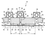
Un mode de réalisation de l'invention sera décrit à présent, en détail, en regard de l'unique figure annexée qui représente schématiquement la buse en coupe transversale.An embodiment of the invention will now be described in detail with reference to the single appended figure which schematically represents the nozzle in cross section.
La figure montre un ruban de verre 10 surnageant la surface d'un bain de métal 12, par exemple de l'étain en fusion à l'intérieur d'une enceinte non représentée contenant le bain d'étain. Le verre se déverse sur le bain à partir d'un four de fusion de verre, non représenté, situé à gauche de la figure. Il s'y étale jusqu'à former un ruban, lequel est extrait du bain à une vitesse constante dans le sens de la flèche f par des moyens extracteurs montés à la sortie du bain.The figure shows a
Au-dessus du ruban de verre 10, dans une zone du bain float où il a acquis une stabilité dimensionnelle, est montée une buse 14 pour l'amenée de gaz de revêtement. La buse est disposée transversalement au ruban de verre et elle s'étend sur toute la largeur de ce dernier. Elle comprend un profilé 16, de section en U retourné dont les bords des parois verticales sont fixés sur des consoles horizontales 18, 20. Celles-ci définissent entre elles une ouverture oblongue 22 transversale par rapport au ruban et ayant une longueur égale à la largeur du ruban.Above the
Dans la chambre 24, définie par le profilé, est logé un conduit d'amenée de gaz 26 percé sur toute sa longueur de trous 27. Le gaz s'étend dans la chambre 24 où il se met à une pression uniforme et s'écoule à travers l'ouverture 22.In the
La buse comprend un talon profilé amont 30, un premier bloc profilé central 32, un second bloc profilé central 34 et un talon profilé aval 36, disposés dans cet ordre, d'amont en aval, au-dessus du ruban de verre 10.The nozzle comprises an upstream profiled
Ces éléments, qui sont tous usuellement réalisés en carbone, s'étendent chacun sur toute la largeur du ruban de verre et définissent entre eux et avec celui-ci un passage d'injection vertical 38 compris entre les parois latérales contiguës des deux blocs centraux et se raccordant à l'ouverture 22, un passage amont 40 et un passage aval 42 horizontaux, d'épaisseur constante (environ 3 à 6 mm) définis respectivement entre les parois inférieures des blocs centraux et le ruban de verre, un passage d'aspiration amont 44 formé entre le talon amont 30 et le premier bloc central 32 et un passage d'aspiration aval 46 compris entre le second bloc central 34 et le talon aval 36.These elements, which are all usually made of carbon, each extend over the entire width of the glass ribbon and define between them and with it a
A la sortie des passages d'aspiration 44 et 46 sont adaptés des moyens d'aspiration, constitués de façon connue en soi par des conduits 48, 50 percés de trous 52 et s'étendant sur toute la largeur de l'installation. Ces conduits sont logés dans des profilés 54, 56 en U retourné, fixés sur les blocs centraux et sur les talons par l'intermédiaire des consoles 58, 60 et 62, 64.At the outlet of the
Le courant gazeux arrivant du conduit d'alimentation 26 descend par le passage d'injection 38, puis se partage en deux parties : un courant amont 66 s'écoulant dans le passage horizontal amont 40 dans le sens inverse de celui du mouvement du ruban de verre, et un courant aval 68 qui s'écoule dans le passage aval 42 dans le même sens que celui du mouvement du ruban de verre. Enfin, le courant amont et le courant aval sont aspirés à travers les passages d'aspiration amont 44 et aval 46.The gas stream arriving from the
Conformément à l'invention, pour éviter que l'éventuel encrassement des talons amont et aval 30 et 36 ne perturbe l'écoulement gazeux, les faces inférieures 70, 72 de ces derniers sont avantageusement surélevées par rapport au ruban de verre 10, à une distance suffisante, par exemple comprise entre 3 et 50 mm et, de préférence, entre 10 et 30 mm et même entre 10 et 20 mm. Cet écartement n'entraîne cependant pas l'apparition de fuites de gaz de revêtement sous les talons car, en raison de la dépression qui est créée par l'aspiration dans les passages d'aspiration 44, 46, des contre-courants de gaz ambiant 74, 76 s'établissent sous ces talons en sens inverse des courants amont et aval 66 et 68 et bloquent ainsi toute fuite.In accordance with the invention, in order to prevent any possible fouling of the upstream and
Comme on l'a indiqué précédemment, pour optimiser le coût résultant de la consommation en réactifs gazeux et l'encombrement de la buse, on dimensionne les blocs centraux 32, 34 de telle sorte que le temps de contact de gaz de revêtement avec le ruban de verre 10 soit égal pour le courant amont 66 et pour le courant aval 68.As indicated above, to optimize the cost resulting from the consumption of gaseous reagents and the size of the nozzle, the
On désignera par :
- ■ L₁ la longueur du bloc central 32,
- ■ L₂ la longueur du bloc central 34,
- ■ V₁ la vitesse débitante à laquelle le gaz remonte dans le passage amont 40,
- ■ V₂ la vitesse débitant à laquelle le gaz descend dans le
passage aval 42, - ■ v la vitesse de défilement du ruban de verre,
- ■ Δ P₁ la perte de charge en amont, et
- ■ Δ P₂ la perte de charge en aval.
- The length of the
central block 32, - The length of the
central block 34, - ■ V₁ the flow rate at which the gas rises in the
upstream passage 40, - ■ V₂ the rate of flow at which the gas descends in the
downstream passage 42, - ■ v the running speed of the glass ribbon,
- ■ Δ P₁ the pressure drop upstream, and
- ■ Δ P₂ the pressure drop downstream.
L'égalité des temps de contact du gaz avec le ruban de verre en amont et en aval se traduit par l'équation :![]()
![]()
L'égalité de fait des pertes de charge amont et aval s'écrit :![]()
![]()
On pose :![]()
![]()
On sait que V = Q/e, où Q est le débit par mètre de largeur du buse et e est l'épaisseur de la lame de gaz comprise entre les blocs centraux et le ruban de verre.We know that V = Q / e, where Q is the flow rate per meter of width of the nozzle and e is the thickness of the gas plate between the central blocks and the glass ribbon.
Compte-tenu de (1), l'équation (2) devient :![]()
![]()
![]()
![]()
![]()
![]()
![]()
![]()
On donnera à présent une application numérique : soit![]()
![]()
![]()
![]()
![]()
![]()
On obtient :![]()
![]()
![]()
![]()
La résolution du système d'équations (6), (7) donne :![]()
![]()
![]()
![]()
Une telle buse avec des proportions optimisées possède un rendement élevé et elle autorise des dépôts considérés comme impossibles avec des buses classiques.Such a nozzle with optimized proportions has a high efficiency and it allows deposits considered to be impossible with conventional nozzles.
Une telle buse peut être montée à l'intérieur d'une enceinte float comme décrit, mais elle peut également être montée hors float.Such a nozzle can be mounted inside a float enclosure as described, but it can also be mounted outside the float.
En outre, des moyens d'aspiration complémentaire peuvent être mis en place en amont et/ou en aval de cette buse, en particulier si l'un des talons n'est pas surélevé, par exemple le talon amont, du côté de ce talon non surélevé.In addition, additional suction means can be installed upstream and / or downstream of this nozzle, in particular if one of the heels is not raised, for example the upstream heel, on the side of this heel. not raised.
Claims (8)
Applications Claiming Priority (2)
| Application Number | Priority Date | Filing Date | Title |
|---|---|---|---|
| FR9101682A FR2672518B1 (en) | 1991-02-13 | 1991-02-13 | NOZZLE WITH DISSYMMETRIC SUPPLY FOR THE FORMATION OF A COATING LAYER ON A TAPE OF GLASS, BY PYROLYSIS OF A GAS MIXTURE. |
| FR9101682 | 1991-02-13 |
Publications (2)
| Publication Number | Publication Date |
|---|---|
| EP0499524A1 true EP0499524A1 (en) | 1992-08-19 |
| EP0499524B1 EP0499524B1 (en) | 1998-06-03 |
Family
ID=9409668
Family Applications (1)
| Application Number | Title | Priority Date | Filing Date |
|---|---|---|---|
| EP92400344A Expired - Lifetime EP0499524B1 (en) | 1991-02-13 | 1992-02-11 | Asymmetrical gas feeding nozzle for coating a glass ribbon by pyrolysis of a gas mixture |
Country Status (6)
| Country | Link |
|---|---|
| US (1) | US5286295A (en) |
| EP (1) | EP0499524B1 (en) |
| JP (1) | JP3256258B2 (en) |
| DE (1) | DE69225730T2 (en) |
| ES (1) | ES2118798T3 (en) |
| FR (1) | FR2672518B1 (en) |
Cited By (16)
| Publication number | Priority date | Publication date | Assignee | Title |
|---|---|---|---|---|
| EP0611733A2 (en) * | 1993-02-16 | 1994-08-24 | Ppg Industries, Inc. | Coating apparatus, method of coating glass, compounds and compositions for coating glass and coated glass substrates |
| FR2724923A1 (en) * | 1994-09-27 | 1996-03-29 | Saint Gobain Vitrage | TECHNIQUE FOR DEPOSITION OF PYROLYSIS COATINGS OF PRECURSOR GAS COMPOSITION (S) |
| US5709726A (en) * | 1993-01-11 | 1998-01-20 | Glaverbel | Device for forming a pyrolytic coating on a hot glass substrate |
| US5776236A (en) * | 1993-02-16 | 1998-07-07 | Ppg Industries, Inc. | Mixed metal oxide film having an accelerant |
| US5863337A (en) * | 1993-02-16 | 1999-01-26 | Ppg Industries, Inc. | Apparatus for coating a moving glass substrate |
| GB2333781A (en) * | 1998-01-19 | 1999-08-04 | Libbey Owens Ford Co | CVD coater for glass using two exhaust towers |
| EP2440686A1 (en) * | 2009-06-08 | 2012-04-18 | Synos Technology, Inc. | Vapor deposition reactor and method for forming thin film |
| US8470718B2 (en) | 2008-08-13 | 2013-06-25 | Synos Technology, Inc. | Vapor deposition reactor for forming thin film |
| US8770142B2 (en) | 2008-09-17 | 2014-07-08 | Veeco Ald Inc. | Electrode for generating plasma and plasma generator |
| US8771791B2 (en) | 2010-10-18 | 2014-07-08 | Veeco Ald Inc. | Deposition of layer using depositing apparatus with reciprocating susceptor |
| US8840958B2 (en) | 2011-02-14 | 2014-09-23 | Veeco Ald Inc. | Combined injection module for sequentially injecting source precursor and reactant precursor |
| US8851012B2 (en) | 2008-09-17 | 2014-10-07 | Veeco Ald Inc. | Vapor deposition reactor using plasma and method for forming thin film using the same |
| US8871628B2 (en) | 2009-01-21 | 2014-10-28 | Veeco Ald Inc. | Electrode structure, device comprising the same and method for forming electrode structure |
| US8877300B2 (en) | 2011-02-16 | 2014-11-04 | Veeco Ald Inc. | Atomic layer deposition using radicals of gas mixture |
| US8895108B2 (en) | 2009-02-23 | 2014-11-25 | Veeco Ald Inc. | Method for forming thin film using radicals generated by plasma |
| US9163310B2 (en) | 2011-02-18 | 2015-10-20 | Veeco Ald Inc. | Enhanced deposition of layer on substrate using radicals |
Families Citing this family (7)
| Publication number | Priority date | Publication date | Assignee | Title |
|---|---|---|---|---|
| FR2736632B1 (en) * | 1995-07-12 | 1997-10-24 | Saint Gobain Vitrage | GLAZING PROVIDED WITH A CONDUCTIVE AND / OR LOW-EMISSIVE LAYER |
| US20100037820A1 (en) * | 2008-08-13 | 2010-02-18 | Synos Technology, Inc. | Vapor Deposition Reactor |
| US20100037824A1 (en) * | 2008-08-13 | 2010-02-18 | Synos Technology, Inc. | Plasma Reactor Having Injector |
| US20110076421A1 (en) * | 2009-09-30 | 2011-03-31 | Synos Technology, Inc. | Vapor deposition reactor for forming thin film on curved surface |
| KR101509864B1 (en) * | 2012-11-07 | 2015-04-06 | (주)엘지하우시스 | Apparatus for cleaning powder |
| JP6640781B2 (en) * | 2017-03-23 | 2020-02-05 | キオクシア株式会社 | Semiconductor manufacturing equipment |
| CN112777943B (en) * | 2021-03-02 | 2021-11-19 | 浙江大学 | Reactor for chemical vapor deposition method coated glass |
Citations (3)
| Publication number | Priority date | Publication date | Assignee | Title |
|---|---|---|---|---|
| US3674453A (en) * | 1968-08-16 | 1972-07-04 | Pilkington Brothers Ltd | Production of float glass having an oxidized metal-modified surface |
| EP0329519A1 (en) * | 1988-02-09 | 1989-08-23 | Saint-Gobain Vitrage International | Process and apparatus for coating a substrate such as a glass ribbon with a pulverulent material |
| EP0365240A1 (en) * | 1988-10-14 | 1990-04-25 | Pilkington Plc | Coating glass |
Family Cites Families (6)
| Publication number | Priority date | Publication date | Assignee | Title |
|---|---|---|---|---|
| US3850679A (en) * | 1972-12-15 | 1974-11-26 | Ppg Industries Inc | Chemical vapor deposition of coatings |
| GB1507996A (en) * | 1975-06-11 | 1978-04-19 | Pilkington Brothers Ltd | Coating glass |
| US5122394A (en) * | 1985-12-23 | 1992-06-16 | Atochem North America, Inc. | Apparatus for coating a substrate |
| US5065696A (en) * | 1987-05-18 | 1991-11-19 | Libbey-Owens-Ford Co. | Temperature controlled distributor beam for chemical vapor deposition |
| US4793282A (en) * | 1987-05-18 | 1988-12-27 | Libbey-Owens-Ford Co. | Distributor beam for chemical vapor deposition on glass |
| GB8824104D0 (en) * | 1988-10-14 | 1988-11-23 | Pilkington Plc | Process for coating glass |
-
1991
- 1991-02-13 FR FR9101682A patent/FR2672518B1/en not_active Expired - Fee Related
-
1992
- 1992-02-03 US US07/829,505 patent/US5286295A/en not_active Expired - Lifetime
- 1992-02-11 ES ES92400344T patent/ES2118798T3/en not_active Expired - Lifetime
- 1992-02-11 DE DE69225730T patent/DE69225730T2/en not_active Expired - Fee Related
- 1992-02-11 EP EP92400344A patent/EP0499524B1/en not_active Expired - Lifetime
- 1992-02-12 JP JP02508792A patent/JP3256258B2/en not_active Expired - Fee Related
Patent Citations (3)
| Publication number | Priority date | Publication date | Assignee | Title |
|---|---|---|---|---|
| US3674453A (en) * | 1968-08-16 | 1972-07-04 | Pilkington Brothers Ltd | Production of float glass having an oxidized metal-modified surface |
| EP0329519A1 (en) * | 1988-02-09 | 1989-08-23 | Saint-Gobain Vitrage International | Process and apparatus for coating a substrate such as a glass ribbon with a pulverulent material |
| EP0365240A1 (en) * | 1988-10-14 | 1990-04-25 | Pilkington Plc | Coating glass |
Non-Patent Citations (1)
| Title |
|---|
| CHEMICAL ABSTRACTS, vol. 98, no. 14, Avril 1983, Columbus, Ohio, US; abstract no. 112478S, NIPPON SHEET GLASS CO. LTD.: 'Apparatus for making metal oxide-coated ribbon - like glass' page 307 ;colonne 1 ; * |
Cited By (22)
| Publication number | Priority date | Publication date | Assignee | Title |
|---|---|---|---|---|
| US5709726A (en) * | 1993-01-11 | 1998-01-20 | Glaverbel | Device for forming a pyrolytic coating on a hot glass substrate |
| US6112554A (en) * | 1993-01-11 | 2000-09-05 | Glaverbel | Device for forming a pyrolytic coating |
| EP0611733A3 (en) * | 1993-02-16 | 1997-05-07 | Ppg Industries Inc | Coating apparatus, method of coating glass, compounds and compositions for coating glass and coated glass substrates. |
| US5776236A (en) * | 1993-02-16 | 1998-07-07 | Ppg Industries, Inc. | Mixed metal oxide film having an accelerant |
| US5863337A (en) * | 1993-02-16 | 1999-01-26 | Ppg Industries, Inc. | Apparatus for coating a moving glass substrate |
| EP0611733A2 (en) * | 1993-02-16 | 1994-08-24 | Ppg Industries, Inc. | Coating apparatus, method of coating glass, compounds and compositions for coating glass and coated glass substrates |
| US5704982A (en) * | 1994-09-27 | 1998-01-06 | Saint-Gobain Vitrage | Technique for depositing coatings by pyrolysis/decomposition of precursor gas or gases |
| EP0708062A1 (en) | 1994-09-27 | 1996-04-24 | Saint-Gobain Vitrage | Pyrolytic coating technique of gaseous precursor compositions |
| FR2724923A1 (en) * | 1994-09-27 | 1996-03-29 | Saint Gobain Vitrage | TECHNIQUE FOR DEPOSITION OF PYROLYSIS COATINGS OF PRECURSOR GAS COMPOSITION (S) |
| GB2333781A (en) * | 1998-01-19 | 1999-08-04 | Libbey Owens Ford Co | CVD coater for glass using two exhaust towers |
| US8470718B2 (en) | 2008-08-13 | 2013-06-25 | Synos Technology, Inc. | Vapor deposition reactor for forming thin film |
| US8851012B2 (en) | 2008-09-17 | 2014-10-07 | Veeco Ald Inc. | Vapor deposition reactor using plasma and method for forming thin film using the same |
| US8770142B2 (en) | 2008-09-17 | 2014-07-08 | Veeco Ald Inc. | Electrode for generating plasma and plasma generator |
| US8871628B2 (en) | 2009-01-21 | 2014-10-28 | Veeco Ald Inc. | Electrode structure, device comprising the same and method for forming electrode structure |
| US8895108B2 (en) | 2009-02-23 | 2014-11-25 | Veeco Ald Inc. | Method for forming thin film using radicals generated by plasma |
| EP2440686A1 (en) * | 2009-06-08 | 2012-04-18 | Synos Technology, Inc. | Vapor deposition reactor and method for forming thin film |
| US8758512B2 (en) | 2009-06-08 | 2014-06-24 | Veeco Ald Inc. | Vapor deposition reactor and method for forming thin film |
| EP2440686A4 (en) * | 2009-06-08 | 2013-01-02 | Synos Technology Inc | Vapor deposition reactor and method for forming thin film |
| US8771791B2 (en) | 2010-10-18 | 2014-07-08 | Veeco Ald Inc. | Deposition of layer using depositing apparatus with reciprocating susceptor |
| US8840958B2 (en) | 2011-02-14 | 2014-09-23 | Veeco Ald Inc. | Combined injection module for sequentially injecting source precursor and reactant precursor |
| US8877300B2 (en) | 2011-02-16 | 2014-11-04 | Veeco Ald Inc. | Atomic layer deposition using radicals of gas mixture |
| US9163310B2 (en) | 2011-02-18 | 2015-10-20 | Veeco Ald Inc. | Enhanced deposition of layer on substrate using radicals |
Also Published As
| Publication number | Publication date |
|---|---|
| JP3256258B2 (en) | 2002-02-12 |
| FR2672518A1 (en) | 1992-08-14 |
| JPH04310543A (en) | 1992-11-02 |
| FR2672518B1 (en) | 1995-05-05 |
| ES2118798T3 (en) | 1998-10-01 |
| DE69225730D1 (en) | 1998-07-09 |
| US5286295A (en) | 1994-02-15 |
| DE69225730T2 (en) | 1999-03-11 |
| EP0499524B1 (en) | 1998-06-03 |
Similar Documents
| Publication | Publication Date | Title |
|---|---|---|
| EP0499524B1 (en) | Asymmetrical gas feeding nozzle for coating a glass ribbon by pyrolysis of a gas mixture | |
| EP0518755B1 (en) | Technique for forming a coating, essentially containing oxygen and silicium, by pyrolysis in the vapour phase | |
| LU84539A1 (en) | INSTALLATION FOR CONTINUOUSLY DEPOSITING, ON THE SURFACE OF A SUBSTRATE CARRIED AT HIGH TEMPERATURE, A LAYER OF A SOLID MATERIAL | |
| FR2542636A1 (en) | METHOD AND DEVICE FOR REGULARLY DISPENSING A PULVERULENT SOLID ON A SUBSTRATE FOR COATING IT AND SUBSTRATE THUS COATED | |
| BE1008560A3 (en) | Device and method for forming a coating pyrolysis. | |
| EP0023472B1 (en) | Process for continuously coating, at least a part of one side at least, of a metallic substrate and apparatus used therefor | |
| EP0006064B1 (en) | Apparatus for the homogeneous distribution of powderlike material through a longitudinal slit, and applications of this apparatus | |
| LU86666A1 (en) | METHOD AND DEVICE FOR FORMING A COATING ON GLASS | |
| EP0156857A1 (en) | Method and apparatus for coating a substrate. | |
| EP0499523B1 (en) | Nozzle with raised downstream toe for deposition of a coating on a sheet of glass by pyrolysis of a gas mixture | |
| EP0704249B1 (en) | Device for distributing pulverulent solids on the surface of a substrate for coating this substrate | |
| FR2545818A1 (en) | METHOD AND DEVICE FOR FORMING A COATING OF METAL COMPOUND ON A HOT SUBSTRATE IN VITREOUS MATERIAL | |
| CH670447A5 (en) | ||
| EP0125153A2 (en) | Method and apparatus for evenly applying a powder coating to a substrate, and substrate thus coated | |
| FR2797277A1 (en) | METHOD AND DEVICE FOR THE CONTINUOUS PRODUCTION OF A METAL SURFACE COATING ON A SLIP | |
| FR2816726A1 (en) | Surface treatment installation has regulator to adjust flow rate of gas drawn out of chamber, so as to maintain zero pressure difference between interior and exterior of chamber | |
| LU86667A1 (en) | GLASS SHEET WITH A COATING | |
| EP0060747B1 (en) | Making glass coated with metallic oxides | |
| EP0612566B1 (en) | Device for distributing powdery solids onto a substrate in order to coat it | |
| EP0374023B1 (en) | Device for coating a moving substrate with a powdery solid material | |
| EP0012679A1 (en) | Apparatus for depositing a film of metal oxides on the surface of flat glass | |
| CH651001A5 (en) | PROCESS AND DEVICE FOR APPLYING A WELDING LAYER TO THE METALLIC MARGINAL PARTS OF A VITREOUS SHEET. | |
| EP1386016B1 (en) | Method and device for dip coating a metal strip | |
| JPS61190054A (en) | One side metal hot dipping device |
Legal Events
| Date | Code | Title | Description |
|---|---|---|---|
| PUAI | Public reference made under article 153(3) epc to a published international application that has entered the european phase |
Free format text: ORIGINAL CODE: 0009012 |
|
| AK | Designated contracting states |
Kind code of ref document: A1 Designated state(s): BE CH DE ES FR GB IT LI LU |
|
| 17P | Request for examination filed |
Effective date: 19930108 |
|
| 17Q | First examination report despatched |
Effective date: 19951004 |
|
| GRAG | Despatch of communication of intention to grant |
Free format text: ORIGINAL CODE: EPIDOS AGRA |
|
| GRAG | Despatch of communication of intention to grant |
Free format text: ORIGINAL CODE: EPIDOS AGRA |
|
| GRAH | Despatch of communication of intention to grant a patent |
Free format text: ORIGINAL CODE: EPIDOS IGRA |
|
| RAP1 | Party data changed (applicant data changed or rights of an application transferred) |
Owner name: SAINT-GOBAIN VITRAGE |
|
| GRAH | Despatch of communication of intention to grant a patent |
Free format text: ORIGINAL CODE: EPIDOS IGRA |
|
| GRAA | (expected) grant |
Free format text: ORIGINAL CODE: 0009210 |
|
| AK | Designated contracting states |
Kind code of ref document: B1 Designated state(s): BE CH DE ES FR GB IT LI LU |
|
| REG | Reference to a national code |
Ref country code: CH Ref legal event code: EP |
|
| REF | Corresponds to: |
Ref document number: 69225730 Country of ref document: DE Date of ref document: 19980709 |
|
| ITF | It: translation for a ep patent filed |
Owner name: RACHELI & C. S.R.L. |
|
| REG | Reference to a national code |
Ref country code: CH Ref legal event code: NV Representative=s name: KIRKER & CIE SA |
|
| GBT | Gb: translation of ep patent filed (gb section 77(6)(a)/1977) |
Effective date: 19980908 |
|
| REG | Reference to a national code |
Ref country code: ES Ref legal event code: FG2A Ref document number: 2118798 Country of ref document: ES Kind code of ref document: T3 |
|
| PLBE | No opposition filed within time limit |
Free format text: ORIGINAL CODE: 0009261 |
|
| STAA | Information on the status of an ep patent application or granted ep patent |
Free format text: STATUS: NO OPPOSITION FILED WITHIN TIME LIMIT |
|
| PGFP | Annual fee paid to national office [announced via postgrant information from national office to epo] |
Ref country code: CH Payment date: 19990517 Year of fee payment: 8 |
|
| 26N | No opposition filed | ||
| PG25 | Lapsed in a contracting state [announced via postgrant information from national office to epo] |
Ref country code: LI Free format text: LAPSE BECAUSE OF NON-PAYMENT OF DUE FEES Effective date: 20000229 Ref country code: CH Free format text: LAPSE BECAUSE OF NON-PAYMENT OF DUE FEES Effective date: 20000229 |
|
| REG | Reference to a national code |
Ref country code: CH Ref legal event code: PL |
|
| REG | Reference to a national code |
Ref country code: GB Ref legal event code: IF02 |
|
| PGFP | Annual fee paid to national office [announced via postgrant information from national office to epo] |
Ref country code: LU Payment date: 20090210 Year of fee payment: 18 Ref country code: ES Payment date: 20090317 Year of fee payment: 18 |
|
| PGFP | Annual fee paid to national office [announced via postgrant information from national office to epo] |
Ref country code: DE Payment date: 20090206 Year of fee payment: 18 |
|
| PGFP | Annual fee paid to national office [announced via postgrant information from national office to epo] |
Ref country code: GB Payment date: 20090211 Year of fee payment: 18 |
|
| PGFP | Annual fee paid to national office [announced via postgrant information from national office to epo] |
Ref country code: BE Payment date: 20090220 Year of fee payment: 18 |
|
| PGFP | Annual fee paid to national office [announced via postgrant information from national office to epo] |
Ref country code: IT Payment date: 20090217 Year of fee payment: 18 |
|
| PGFP | Annual fee paid to national office [announced via postgrant information from national office to epo] |
Ref country code: FR Payment date: 20090213 Year of fee payment: 18 |
|
| BERE | Be: lapsed |
Owner name: *SAINT-GOBAIN VITRAGE Effective date: 20100228 |
|
| GBPC | Gb: european patent ceased through non-payment of renewal fee |
Effective date: 20100211 |
|
| REG | Reference to a national code |
Ref country code: FR Ref legal event code: ST Effective date: 20101029 |
|
| PG25 | Lapsed in a contracting state [announced via postgrant information from national office to epo] |
Ref country code: FR Free format text: LAPSE BECAUSE OF NON-PAYMENT OF DUE FEES Effective date: 20100301 |
|
| PG25 | Lapsed in a contracting state [announced via postgrant information from national office to epo] |
Ref country code: DE Free format text: LAPSE BECAUSE OF NON-PAYMENT OF DUE FEES Effective date: 20100901 Ref country code: BE Free format text: LAPSE BECAUSE OF NON-PAYMENT OF DUE FEES Effective date: 20100228 |
|
| REG | Reference to a national code |
Ref country code: ES Ref legal event code: FD2A Effective date: 20110308 |
|
| PG25 | Lapsed in a contracting state [announced via postgrant information from national office to epo] |
Ref country code: IT Free format text: LAPSE BECAUSE OF NON-PAYMENT OF DUE FEES Effective date: 20100211 Ref country code: GB Free format text: LAPSE BECAUSE OF NON-PAYMENT OF DUE FEES Effective date: 20100211 |
|
| PG25 | Lapsed in a contracting state [announced via postgrant information from national office to epo] |
Ref country code: ES Free format text: LAPSE BECAUSE OF NON-PAYMENT OF DUE FEES Effective date: 20110307 |
|
| PG25 | Lapsed in a contracting state [announced via postgrant information from national office to epo] |
Ref country code: ES Free format text: LAPSE BECAUSE OF NON-PAYMENT OF DUE FEES Effective date: 20100212 |
|
| PG25 | Lapsed in a contracting state [announced via postgrant information from national office to epo] |
Ref country code: LU Free format text: LAPSE BECAUSE OF NON-PAYMENT OF DUE FEES Effective date: 20100211 |