EP0498787A2 - Method and device for manufacturing insulating glazing units - Google Patents
Method and device for manufacturing insulating glazing units Download PDFInfo
- Publication number
- EP0498787A2 EP0498787A2 EP92890021A EP92890021A EP0498787A2 EP 0498787 A2 EP0498787 A2 EP 0498787A2 EP 92890021 A EP92890021 A EP 92890021A EP 92890021 A EP92890021 A EP 92890021A EP 0498787 A2 EP0498787 A2 EP 0498787A2
- Authority
- EP
- European Patent Office
- Prior art keywords
- gas
- air
- mixture
- insulating glass
- spacer frame
- Prior art date
- Legal status (The legal status is an assumption and is not a legal conclusion. Google has not performed a legal analysis and makes no representation as to the accuracy of the status listed.)
- Withdrawn
Links
Images


Classifications
-
- E—FIXED CONSTRUCTIONS
- E06—DOORS, WINDOWS, SHUTTERS, OR ROLLER BLINDS IN GENERAL; LADDERS
- E06B—FIXED OR MOVABLE CLOSURES FOR OPENINGS IN BUILDINGS, VEHICLES, FENCES OR LIKE ENCLOSURES IN GENERAL, e.g. DOORS, WINDOWS, BLINDS, GATES
- E06B3/00—Window sashes, door leaves, or like elements for closing wall or like openings; Layout of fixed or moving closures, e.g. windows in wall or like openings; Features of rigidly-mounted outer frames relating to the mounting of wing frames
- E06B3/66—Units comprising two or more parallel glass or like panes permanently secured together
- E06B3/677—Evacuating or filling the gap between the panes ; Equilibration of inside and outside pressure; Preventing condensation in the gap between the panes; Cleaning the gap between the panes
- E06B3/6775—Evacuating or filling the gap during assembly
-
- E—FIXED CONSTRUCTIONS
- E06—DOORS, WINDOWS, SHUTTERS, OR ROLLER BLINDS IN GENERAL; LADDERS
- E06B—FIXED OR MOVABLE CLOSURES FOR OPENINGS IN BUILDINGS, VEHICLES, FENCES OR LIKE ENCLOSURES IN GENERAL, e.g. DOORS, WINDOWS, BLINDS, GATES
- E06B3/00—Window sashes, door leaves, or like elements for closing wall or like openings; Layout of fixed or moving closures, e.g. windows in wall or like openings; Features of rigidly-mounted outer frames relating to the mounting of wing frames
- E06B3/66—Units comprising two or more parallel glass or like panes permanently secured together
- E06B3/673—Assembling the units
- E06B3/67304—Preparing rigid spacer members before assembly
- E06B3/67321—Covering spacer elements, e.g. with sealants
Definitions
- the invention relates to a method for producing double or multi-pane insulating glass, in which spacer frames are coated on both sides with sealant or adhesive, at least two glass panes are put together with the spacer frame to form an insulating glass pane blank and, after the insulating glass pane blank has been put together, the air contained in the space between the panes is at least partially preferably about 90% by a heavy gas, e.g. Sulfur hexafluoride or argon is replaced.
- a heavy gas e.g. Sulfur hexafluoride or argon
- the air in the space between the glass panes of insulating glass panes is used to improve heat and sound insulation, i.e. overall, the insulating properties of insulating glass panes are increasingly being replaced by gas (e.g. a heavy gas such as argon or sulfur hexafluoride).
- gas e.g. a heavy gas such as argon or sulfur hexafluoride.
- argon or sulfur hexafluoride In order to achieve sufficient insulating properties, it is often necessary to replace at least 90% of the air in the space with the heavy gas.
- the invention has for its object to provide a method of the type mentioned, with which, without having to drill holes in the spacer frame and without glass panes having to be elastically deformed, access to the pane space of the insulating glass blank is possible so that the gas exchange can be carried out.
- this object is achieved by providing at least two interruptions in a strand of sealant or adhesive at a distance from one another, that the spacer frame thus prepared is joined together with the glass panes to form an insulating glass pane blank, and that the gas exchange is carried out by the so between the a glass pane and the spacer frame openings formed.
- interruptions in the strand of sealant or adhesive on a side wall of the spacer frame have a length of about 20 mm, taking into account the fact that the strand is usually 0.8 to 1 mm thick, a sufficiently large cross-sectional area of the openings is achieved, so that the gas exchange in an acceptable time, ie without the cycle time more modern Influencing insulating glass production lines can be carried out.
- interruptions in the strands of sealant or adhesive can also be provided on both side flanks of the spacer frame.
- sealant or adhesive used as a coating for the spacer frame (usually a butyl rubber) is easy to process when it has been heated to the appropriate temperature, it is also not difficult to open the openings after the gas exchange has been carried out. to close again by injecting an appropriate amount of sealant or adhesive.
- This closing is easier than the closing of bores in the spacer frame, since the openings in the invention are delimited by the narrow edges of the strand, by the wall of the spacer frame and by the glass pane.
- Complex measures as are known, for example, from US Pat. No. 4,902,213, EP-A-282 685 or EP-A-185 222, can be dispensed with in the invention.
- the interruptions in the strand of sealant or adhesive can be provided at two points arranged in the area of a corner of the spacer frame.
- This measure has the advantage that the lines for supplying heavy gas and for removing air or heavy gas-air mixture can be positioned in the area of a defined corner of the insulating glass blank. It is possible to work with a device which is constructed in principle as that known from EP-A-324 333, with the proviso that no drills are required to create holes in the spacer frame.
- the procedure is such that the interruptions are generated by, after coating the spacer frame with sealant or adhesive, the sealant or adhesive at at least two spaced locations from a side flank of the spacer frame away.
- the interruptions are generated by, after coating the spacer frame with sealant or adhesive, the sealant or adhesive at at least two spaced locations from a side flank of the spacer frame away.
- the openings between the spacer frame and the glass sheet are closed by injecting a sealing compound after the gas exchange has ended.
- the procedure is preferably such that the amount of sealing compound which corresponds to the volume of the opening is injected from the outside into each opening. It is preferred that the sealing compound is injected into the opening starting at one end of the opening and progressively being injected along the opening in a direction parallel to the leg of the spacer frame.
- An advantageous device for performing the method is based on a known device for coating spacer frames on both side flanks with sealant or adhesive, in particular with butyl rubber.
- Such devices are known from AT-PS 315 404, AT-PS 365 550, AT-PS 356 832, DE-OS 39 06 293 and DE-OS 40 20 812.
- such a device (“butyl machine”) is characterized in that a device is provided in the device which removes sealant or adhesive from a side flank of the spacer frame at at least two spaced apart locations. If openings are to be present on both sides of the spacer frame, the device is designed such that it can remove sealant or adhesive from both side flanks of the spacer frame.
- the removal of the application of sealant or adhesive from a side wall of the spacer frame is particularly simple if it is provided that the device has two scrapers that can be displaced along a wall of the spacer frame. If the scraper used in this embodiment has sharp side edges and rests elastically on the spacer frame, there are also no problems when separating the sealant or adhesive agent to be removed from the sealant or adhesive remaining on the spacer frame.
- the device for removing sealant or adhesive has a stop at a predetermined distance for the spacer frame, which is arranged in the region of the conveyor of the device for coating spacer frames.
- the nozzles for the gas exchange have rectangular mouths corresponding to the openings provided between the glass pane and spacer frame and that the nozzles have contact surfaces with which they, on the one hand, protrude from the edge of the glass pane above the spacer frame and on the other hand can be sealingly applied to the outwardly facing surface of the spacer frame, then special sealing measures, such as are also known, for example, from EP-A-276 647, are unnecessary.
- the invention further relates to a method for filling the interior of insulating glass panes with gas, in which a gas other than air, such as a heavy gas or an inert gas, is introduced into the interior of the insulating glass pane and air or a mixture of air and gas is withdrawn, wherein this method should be used in particular and advantageously in conjunction with the method according to one of claims 1 to 7 and in which gas losses can be largely avoided.
- a gas other than air such as a heavy gas or an inert gas
- the gas which is to replace the air in the interior of the insulating glass pane is separated from the mixture of air and gas drawn from the interior of the insulating glass pane and is used again for filling insulating glass panes, gas losses are avoided or at least kept smaller than before .
- Known working techniques can be used to separate the gas from the mixture of gas and air.
- reference is made to the possibility of separating the mixture into air and gas by liquefaction and fractional evaporation or by selective adsorption of one of the two components of the mixture of air and gas.
- the gas separated from the mixture of gas and air is stored and that after reaching a predetermined, optionally adjustable amount of stored gas, gas is used for filling insulating glass panes.
- This embodiment offers the possibility of storing the gas obtained in the course of the filling process of one or more insulating glass panes by separating the mixture and (later) for filling (further) insulating glass panes.
- the procedure is followed so that the mixture of air and gas is stored before the mixture is separated or gas is separated from the mixture.
- This embodiment of the method according to the invention has the advantage that the separation is only carried out after a certain amount of mixture has accumulated which is sufficient for the separation of the air and gas or the separation of gas to be carried out economically.
- gas and air or a mixture of air and gas are supplied or discharged through openings which are interrupted in the coating of the spacer frame made of sealant or adhesive, e.g. Butyl rubber are formed.
- the invention also extends to a device for carrying out the method according to claims 8 to 17 with a storage container for the gas, with which the interior of the insulating glass panes is to be filled, with a line from the storage container for gas to at least one probe through which the gas is inserted into the interior of the insulating glass pane when the probe is in close contact with the inlet opening, and with at least one further probe which is sealingly applied to an outlet opening for air or a mixture of air and gas.
- this device is characterized in that the air or mixture outlet opening Line leading away from air and gas to a device for separating gas from the withdrawn mixture of air and gas leads to the provision of a line through which the device for separating gas is connected to a store for separated special gas and from the store leads away a line that leads to the line to the probe for introducing gas into the interior of the insulating glass pane.
- this device can be characterized in that a device is provided which detects the filling level of the storage for the separated gas and which controls a valve which is provided in the line between the storage tank for gas and the nozzle or probe, and that in the line from the store for separated gas to the line to the nozzle or probe a controlled by the device for detecting the filling level of the memory, optionally with the valve and the line between the reservoir and nozzle or probe to a reusable valve is provided, and that the supply of gas from the storage for separated gas or from the storage container is released during operation of the device. It is preferred according to the invention if the device is a pressure sensor.
- the supply of gas to the nozzle or probe, via which the interior of the insulating glass pane is filled with gas, is improved if, according to a proposal of the invention, it is provided that a device for increasing the pressure, in particular a pump, is provided in the line leading away from the storage for the gas or the like is provided.
- an intermediate store for the mixture is provided in front of the device for separating gas from the mixture of air and gas drawn off from the interior of the insulating glass pane.
- a device measuring the content of the mixture of gas to be separated and one of outgoing line Derivation is provided, and that a shut-off device assigned to the derivation is provided, which is controlled by the device.
- This embodiment allows the separation of the mixture of air and gas only to begin when a predetermined content of gas in the mixture has been exceeded.
- the device proposed for carrying out the method according to the invention can also be designed, as is known per se. Examples of these are shown and described in EP-A-276 647 or 324 333 and DE-GM 9 014 309.
- An insulating glass blank 1 consists of two glass sheets 10 and 11 and an interposed spacer frame 12, which carries 15 coatings (strands 13) of adhesive or sealant, in particular of butyl rubber, on its two side walls.
- Devices to provide the spacer frame 12 on both side walls with the coatings of sealing or adhesive, so-called butyl machines, are known in a wide variety of embodiments. Examples of this are mentioned in the introduction to the description.
- Insulating glass blanks i.e. Insulating glass panes, which are not yet filled with sealing compound in the area of their edge joint 14, are assembled from two glass panes 10 and 11 and the spacer frame 12 inserted between them in so-called assembly stations.
- assembly stations are known for example from AT-PS 370 201 and AT-PS 370 706.
- assembly stations can also be combined with automatic devices for attaching the spacer frames to one of the insulating glass panes (cf. DE-OS 32 23 848, US Pat. No. 4,836,005 or AT-PS 390 434).
- FIG. 2 shows, in the area of the corner 21 of the insulating glass blank 1, an opening 22 and an opening 23. Both the opening 22 and the opening 23rd are from the openings 22 and 23 facing surface of the glass sheet 10, the facing wall 5 of the Spacer frame 12 and from the end faces of the strands 20 and 13 '13' adjacent to the interruptions of adhesive or sealing compound.
- the gas exchange can be carried out via these two openings 22 and 23, as will be explained below with reference to FIGS. 3 to 5.
- a nozzle 30 is brought into position in the area of the opening 22, as is indicated schematically in FIG. 2 ".
- the nozzle 30 has an opening 31, the rectangular cross-sectional shape of which corresponds to the rectangular cross-sectional shape of the opening 22.
- the nozzle 30 has a surface 32 which bears against the inside of the edge of the glass pane 10 which projects outwardly beyond the spacer frame 12 and furthermore an inclined surface 33 which bears against the surface of the spacer frame 12 located outside the sealing material strand 13
- a good seal of the nozzle 30 is achieved without additional sealing measures and an almost loss-free passage of gas into the interior 24 of the insulating glass blank 1.
- a nozzle 35 can be used, which is constructed similarly to the nozzle 30 and in the region of the opening 23, i.e. the opening further away from corner 21 is brought into position between glass pane 10 and spacer frame 12.
- the nozzle 30 for supplying gas and the nozzle 35 for extracting air or air / heavy gas mixture from the interior 24 can be mounted on a common carrier 3, which is in the area of the corner 21 of the insulating glass blank is brought into position.
- This embodiment will be chosen in particular if - what is readily possible - (see below) ensures that the openings 22 and 23 have a predetermined, known distance from the corner 21 of the insulating glass blank 1, which is the distance between the nozzles 30 and 35 on the carrier 3 corresponds.
- the insulating glass blank 1 which is conveyed up from an assembly station, is conveyed into a press which, for example, describes that described in DE-PS 31 30 645, AT-PS 385 499 or Austrian patent application 2956/87 published on June 15, 1990 Can have construction.
- a press which, for example, describes that described in DE-PS 31 30 645, AT-PS 385 499 or Austrian patent application 2956/87 published on June 15, 1990 Can have construction.
- the press the insulating glass blank 1 is pressed and the pressure on the glass sheets 10 and 11 is maintained during the gas exchange.
- the nozzles 30 and 35 are brought into position in the region of the corner 21 with the aid of their support 3 such that they are aligned with the openings 22 and 23 and, as explained with reference to FIG. 2 ", on the spacer frame 12 and rest sealingly on the edge of the glass sheet 10.
- the gas which is to at least partially replace the air in the interior 24 of the insulating glass pane 1, flows into the interior in a horizontally oriented stream at high speed parallel to the lower horizontal edge of the spacer frame 12 24 is blown in between the glass panes 10 and 11.
- the gas flow follows the inner circumference of the spacer frame 12 and compresses towards the center, so that air gradually compresses in an increasingly smaller area and through the opening 23 is displaced from the interior 24 of the insulating glass blank 1, as is indicated in FIGS. 3 to 5 by the "front" 6 between heavy gas and air.
- the gas filling is regulated either by measuring the residual oxygen content in the gas-air mixture drawn from the interior 24 of the insulating glass blank 1, by determining the composition of the air-gas mixture in the interior of the insulating glass blank and / or by determining (calculating) the volume of the Interior 24 and supplying a correspondingly metered amount of gas. In the latter variant, a certain loss is taken into account by the calculated volume by e.g. empirically determined fraction is increased.
- the gas discharged via the nozzle 35 is fed to a device for separating gas in order to avoid gas losses.
- the gas separated in a gas separation device of any design can then either be fed directly to the line for supplying gas to the nozzle 30 or to an intermediate store or else to the storage container for the gas from which it is supplied to the nozzle. With this process variant, losses of gas can be reduced practically to zero. Further details are explained below with reference to FIG. 9.
- a device is described below with the aid of FIGS. 6 to 8, with which the interruptions 20 in a strand 13 of sealant or adhesive can be produced in a simple manner.
- This device is advantageously integrated into an automatic butyl machine, which may have the configuration described above with reference to literature examples.
- the device for Removing the sealant or adhesive in the area of the interruptions 20 a tool 40 which has two scrapers 41.
- the scrapers 41 have a front edge 42 designed as a cutting edge and sharp corners 43 be peeled off or scraped off.
- the tool 40 is mounted on a carrier 45, on which a drive, for example a pressure medium motor or the like, engages and which can be guided on a guide rail.
- a drive for example a pressure medium motor or the like
- the actual tool 40 is designed, for example, to be resilient, so that it rests elastically against the wall 5 of the spacer frame 12, from which the strand 13 of sealant or adhesive is to be peeled off or scraped off in regions.
- the tool 40 is actuated after the spacer frame 12 against a stop 46 which is fixed in its operative position and which has a predetermined distance from the tool 40, has been brought into contact.
- stops are also provided in the known frame coating devices, in particular in the partially or fully automatic devices.
- the openings 22 and 23 are closed with sealing or adhesive, in particular butyl rubber, which are formed by sealing nozzles which are similar to the nozzles 30 and 35 and on a common one Carrier can be mounted, is injected into the openings 22 and 23.
- the injection is very simple with the help of a metering cylinder, which squeezes the exact amount of sealant or adhesive material through the mouths of the closure nozzles.
- both the nozzles 30, 35 for gas exchange and the nozzles for closing can of the openings after the gas exchange has ended, as is known in principle from EP-A-324 333, designed and arranged on a common support which is adjustable relative to the insulating glass blank.
- the openings 22 and 23 can also be closed in such a way that a metered amount of sealant or adhesive (for example butyl rubber) is injected as a sealing compound from a nozzle into openings 22 and 23, respectively, while a relative movement between the nozzle and insulating glass blank 1 is carried out is so that the nozzle moves along the opening during the pressing of the sealing compound into the openings 22 and 23, respectively.
- sealant or adhesive for example butyl rubber
- the openings 22 and 23 can be closed in succession or, if a closure device with two nozzles is provided, also at the same time.
- the interruptions 20 in the strand 13 of sealant or adhesive can also be achieved by temporarily (twice) interrupting the supply of sealant or adhesive without interrupting the advance of the spacer frame to one of the nozzles of the butyl machine.
- two scrapers spaced apart from one another can also be provided, which are fastened on a common carrier or two separate carriers.
- This scraper operates in succession at (at least) two locations on the spacer frame in order to generate the interruptions in the strand.
- This embodiment is particularly advantageous in the case of an automatic butyl machine in which the spacer frame is moved by a gripper or the like (cf. DE-OS 40 20 812).
- the insulating glass blank 1 consisting of the two glass panes 10 and 11 and the spacer frame 12 interposed therebetween, is conveyed into a plate press for filling the interior with a gas other than air, for example as provided in EP-A-276 647, the press plates of which press Apply to the outer sides of the two glass panes 10 and 11 of the insulating glass blank 1 and prevent the glass panes 10 and 11 from detaching from the spacer frame 12 during filling.
- two bores 55 and 56 are provided in the spacer frame 12, through which the interior 24 between the two glass panes 10 and 11, which is delimited all around by the spacer frame 12, is accessible.
- the interior 24 can also be made accessible in that the coating of adhesive or sealant, which is applied to both sides of the spacer frame 12, and through which the glass panes 10 and 11 with the spacer frame 12 are glued, interrupted at least on one side of the spacer frame 12 at two points.
- probes 57 and 58 are inserted, which have seals 59 which permit gas-tight attachment of the probes 57 and 58, so that undesired and uncontrolled escape of gas in the Area of the openings 22, 23 or 55 and 56 is avoided.
- the probes 57, 58 it is also possible to use the nozzles 30, 35 explained above, which, as shown in FIG. 2 ", are applied to the openings 55, 56 and 22, 23, respectively.
- the gas with which the interior 24 is to be filled is removed from a storage container 60 and passed via the open shut-off valve 61 through a line 62 to the probe 57 or nozzle 30 and via this, for example as in DE -GM 9 014 304 described in the interior 24 of the insulating glass panel 1 passed.
- a suction pump 64 Via the probe 58 and a line 63 connected to it, optionally supported by a suction pump 64, initially Air and later a mixture of air and gas with increasing gas content withdrawn from the interior of the insulating glass pane 1.
- a measuring device 65 which determines the content of gas in the withdrawn mixture. It can be provided that the measuring device 65 is functionally connected via a control line 66 to a three-way valve 67, which is either set so that the mixture flows via line 63 into a buffer store 68 or out through a discharge line 69.
- the valve 67 will be controlled so that pure air or air with only a very low gas content flows through the discharge line 69 and is simply blown off or otherwise supplied or disposed of, whereas the valve 67 from a predetermined gas content in the mixture of the Measuring device 65 is adjusted so that the mixture of air and gas flows into the intermediate container 68.
- a pressure sensor 70 is assigned to the intermediate container 68 and controls a valve 72 in a connecting line 73 via a control line 71, which leads to a separating device 74. As soon as a sufficient amount of mixture of gas and air is contained in the intermediate store, the pressure sensor 70 triggers the opening of the valve 72 in the line 73, so that the mixture flows into the separating device 74.
- the mixture is separated into air, which is blown off via a line 75, and gas, which is fed via a further line 76 to a storage 80 for gas.
- a pressure sensor 81 is also assigned to the storage 80 for separated gas.
- the pressure sensor 81 is connected via a control line 82 to a three-way valve 83 provided in the line 62.
- the three-way valve 83 connects a line 84, which comes from the storage 80 for separated gas, to the line 62.
- a pressure booster for example a pump or a blower 86, can also be provided in this line 84.
- the pressure sensor 81 of the memory 80 triggers a switchover of the three-way valve 83 when a predetermined or adjustable pressure is reached in the memory 80, so that gas flows via line 84, three-way valve 83, line 62 and through this to probe 57.
- the device proposed for carrying out the method according to the invention can also be made simpler than the one described with reference to the drawing.
- the measuring device 65 and the valve 67 controlled by it are not absolutely necessary. This also applies to the intermediate storage 68.
Landscapes
- Engineering & Computer Science (AREA)
- Civil Engineering (AREA)
- Structural Engineering (AREA)
- Securing Of Glass Panes Or The Like (AREA)
- Joining Of Glass To Other Materials (AREA)
Abstract
Die für das Herstellen von Isolierglasscheiben (1), bei dem die im zwischen den Glasscheiben angeordneten Raum (24) enthaltene Luft wenigstens teilweise durch ein Sondergas ersetzt ist, nötigen Öffnungen (22, 23) für den Gasaustausch werden hergestellt, indem man in den Strängen (13) aus Dicht- bzw. Klebemasse an wenigstens zwei im Abstand voneinander angeordnete Unterbrechungen (20) vorsieht. Beim Füllen des Innenraumes (24) der Isolierglasscheiben mit Sondergas wird von dem aus dem Innenraum (24) der Isolierglasscheibe (1) abgezogenen Gemisch aus Luft und Gas wenigstens ein Teil des Gases abgetrennt und gespeichert. Nachdem eine bestimmte Menge an Gas gespeichert worden ist, wird gespeichertes Gas zum Füllen des Innenraumes (24) von Isolierglasscheiben (1) verwendet.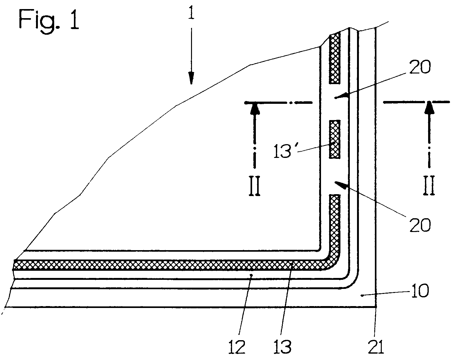
Description
Die Erfindung betrifft ein Verfahren zum Herstellen von Zwei-oder Mehrscheibenisolierglas, bei dem Abstandhalterrahmen beidseitig mit Dicht- bzw. Klebemasse beschichtet, wenigstens zwei Glasscheiben mit dem Abstandhalterrahmen zu einem Isolierglasscheibenrohling zusammengestellt werden und nach dem Zusammenstellen des Isolierglasscheibenrohlings die im Scheibenzwischenraum enthaltene Luft wenigstens teilweise, vorzugsweise zu etwa 90% durch ein Schwergas, z.B. Schwefelhexafluorid oder Argon ersetzt wird.The invention relates to a method for producing double or multi-pane insulating glass, in which spacer frames are coated on both sides with sealant or adhesive, at least two glass panes are put together with the spacer frame to form an insulating glass pane blank and, after the insulating glass pane blank has been put together, the air contained in the space between the panes is at least partially preferably about 90% by a heavy gas, e.g. Sulfur hexafluoride or argon is replaced.
Die im zwischen den Glasscheiben liegenden Raum von Isolierglasscheiben vorhandene Luft wird zur Verbesserung des Wärme-und Schallschutzes, d.h. insgesamt der Isoliereigenschaften von Isolierglasscheiben zunehmend durch Gas (z.B. ein Schwergas, wie Argon oder Schwefelhexafluorid) ersetzt. Dabei ist es, um hinreichende Isoliereigenschaften zu erzielen, oft notwendig, die im Zwischenraum enthaltene Luft zu wenigstens 90% durch das Schwergas zu ersetzen.The air in the space between the glass panes of insulating glass panes is used to improve heat and sound insulation, i.e. overall, the insulating properties of insulating glass panes are increasingly being replaced by gas (e.g. a heavy gas such as argon or sulfur hexafluoride). In order to achieve sufficient insulating properties, it is often necessary to replace at least 90% of the air in the space with the heavy gas.
Bekannte Vorrichtungen zum Durchführen des Gasaustausches arbeiten mit Sonden, die durch Bohrungen im Abstandhalterrahmen eingeführt werden. Solche Vorrichtungen sind beispielsweise aus der DE-OS 30 25 122 und der DE-OS 31 17 256 bekannt. Nachteilig bei diesen Vorrichtungen ist es, daß Löcher im Abstandhalterrahmen hergestellt und diese dann wieder verschlossen werden müssen. Das ist nicht ohne weiteres möglich, da die Abstandhalterrahmen aus Metall bestehen.Known devices for carrying out the gas exchange work with probes which are inserted through holes in the spacer frame. Such devices are known for example from DE-OS 30 25 122 and DE-OS 31 17 256. A disadvantage of these devices is that holes are made in the spacer frame and these then have to be closed again. This is not easily possible because the spacer frames are made of metal.
Es ist auch schon vorgeschlagen worden, die Isolierglasscheiben, noch bevor sie gepreßt werden, d.h. wenn sie im Bereich ihres unteren Randes noch offen sind, mit Schwergas zu füllen und erst dann zum Isolierglasscheibenrohling zu verpressen. Solche Vorrichtungen sind aus der AT-PS 368 985 oder der DE-OS 34 02 323 bekannt. Nachteilig bei diesen bekannten Vorrichtungen ist es, daß große Gasverluste auftreten und gelegentlich (DE-OS 31 01 342) in großen Vakuumkammern gearbeitet werden muß.It has also already been proposed to fill the insulating glass panes with heavy gas before they are pressed, ie if they are still open in the area of their lower edge, and only then to press them into the insulating glass pane blank. Such devices are from AT-PS 368 985 or DE-OS 34 02 323 known. A disadvantage of these known devices is that large gas losses occur and occasionally (DE-OS 31 01 342) must be worked in large vacuum chambers.
Es ist auch schon vorgeschlagen worden, Zugang zum Innenraum der Isolierglasscheibe für das Einführen der Sonden zum Ausführen des Gasaustausches dadurch zu erhalten, daß eine der Glasscheiben beim Zusammenbau des Isolierglasscheibenrohlings im Abstand vom Abstandhalterrahmen gehalten wird, wozu beispielsweise die eine Glasscheibe im Bereich von zwei einander diagonal gegenüberliegenden Ecken elastisch konkav verformt wird (siehe DE-OS 39 14 706).It has also been proposed to obtain access to the interior of the insulating glass pane for the insertion of the probes for carrying out the gas exchange by holding one of the glass panes at a distance from the spacer frame during assembly of the insulating glass pane blank, for which purpose, for example, the one glass pane is in the area of two to one another diagonally opposite corners are deformed elastically concave (see DE-OS 39 14 706).
Dieses zuletzt beschriebene, aus der DE-OS 39 14 706 bekannte Verfahren läßt sich nur bei Isolierglasscheiben mit vergleichsweise dünnen Glasscheiben ausführen, da sich dickere Glasscheiben oder Verbundglasscheiben mit vertretbarem Aufwand nicht mit den erforderlichen, engen Krümmungsradien elastisch verbiegen lassen, um den Zugang in das Innere des Isolierglasscheibenrohlings zum Durchführen des Gasaustausches zu erhalten.This last-described method known from DE-OS 39 14 706 can only be carried out with insulating glass panes with comparatively thin glass panes, since thicker glass panes or laminated glass panes cannot be elastically bent with the necessary, tight radii of curvature with reasonable effort in order to gain access to that Obtain interior of the insulating glass blank for carrying out the gas exchange.
Der Erfindung liegt die Aufgabe zugrunde, ein Verfahren der eingangs genannten Gattung anzugeben, mit dem, ohne daß in den Abstandhalterrahmen Löcher gebohrt und ohne daß Glasscheiben elastisch verformt werden müssen, Zugang in den Scheibenzwischenraum des Isolierglasscheibenrohlings möglich ist, damit der Gasaustausch ausgeführt werden kann.The invention has for its object to provide a method of the type mentioned, with which, without having to drill holes in the spacer frame and without glass panes having to be elastically deformed, access to the pane space of the insulating glass blank is possible so that the gas exchange can be carried out.
Erfindungsgemäß wird diese Aufgabe dadurch gelöst, daß man in einem Strang aus Dicht- bzw. Klebemasse im Abstand voneinander wenigstens zwei Unterbrechungen vorsieht, daß man den so vorbereiteten Abstandhalterrahmen mit den Glasscheiben zu einem Isolierglasscheibenrohling zusammenfügt, und daß man den Gasaustausch durch die so zwischen der einen Glasscheibe und dem Abstandhalterrahmen gebildeten Öffnungen ausführt.According to the invention, this object is achieved by providing at least two interruptions in a strand of sealant or adhesive at a distance from one another, that the spacer frame thus prepared is joined together with the glass panes to form an insulating glass pane blank, and that the gas exchange is carried out by the so between the a glass pane and the spacer frame openings formed.
Insbesondere, wenn die Unterbrechungen in dem Strang aus Dicht- bzw. Klebemasse an einer Seitenwand des Abstandhalterrahmens eine Länge von etwa 20 mm aufweisen, wird unter Berücksichtigung des Umstandes, daß der Strang in der Regel 0,8 bis 1 mm dick ist, eine hinreichend große Querschnittsfläche der Öffnungen erzielt, so daß der Gasaustausch in annehmbarer Zeit, d.h. ohne die Taktzeit moderner Isolierglasherstellungslinien nachteilig zu beeinflussen, durchgeführt werden kann. Allenfalls können Unterbrechungen in den Strängen aus Dicht- bzw. Klebmasse auch auf beiden Seitenflanken des Abstandhalterrahmens vorgesehen werden.In particular, if the interruptions in the strand of sealant or adhesive on a side wall of the spacer frame have a length of about 20 mm, taking into account the fact that the strand is usually 0.8 to 1 mm thick, a sufficiently large cross-sectional area of the openings is achieved, so that the gas exchange in an acceptable time, ie without the cycle time more modern Influencing insulating glass production lines can be carried out. At most, interruptions in the strands of sealant or adhesive can also be provided on both side flanks of the spacer frame.
Da die als Beschichtung für den Abstandhalterrahmen verwendete Dicht- bzw. Klebmasse (in der Regel ein Butylkautschuk) einfach verarbeitbar ist, wenn sie auf die entsprechende Temperatur erwärmt worden ist, macht es auch keine Schwierigkeiten, die Öffnungen, nachdem der Gasaustausch ausgeführt worden ist, durch Einspritzen einer entsprechenden Menge an Dicht- bzw. Klebemasse wieder zu verschließen. Dieses Verschließen ist einfacher als das Verschließen von Bohrungen im Abstandhalterrahmen, da die Öffnungen bei der Erfindung von den Schmalkanten des Stranges, von der Wand des Abstandhalterrahmens und von der Glasscheibe begrenzt sind. Aufwendige Maßnahmen, wie sie beispielsweise aus der US-PS 4 902 213, der EP-A-282 685 oder EP-A-185 222 bekannt sind, sind bei der Erfindung entbehrlich.Since the sealant or adhesive used as a coating for the spacer frame (usually a butyl rubber) is easy to process when it has been heated to the appropriate temperature, it is also not difficult to open the openings after the gas exchange has been carried out. to close again by injecting an appropriate amount of sealant or adhesive. This closing is easier than the closing of bores in the spacer frame, since the openings in the invention are delimited by the narrow edges of the strand, by the wall of the spacer frame and by the glass pane. Complex measures, as are known, for example, from US Pat. No. 4,902,213, EP-A-282 685 or EP-A-185 222, can be dispensed with in the invention.
In der Praxis kann beim eigentlichen Gasaustausch nach dem erfindungsgemäßen Verfahren im übrigen so vorgegangen werden, wie dies aus der EP-B-276 647 bekannt ist. Bei der an sich bekannten Arbeitsweise kann mit entsprechend hohen Gasströmungsgeschwindigkeiten gearbeitet werden, ohne daß die Gefahr besteht, daß sich die Glasscheiben durch den entstehenden Überdruck vom Abstandhalterrahmen lösen und/ oder die Abstandhalterrahmen nach außen wandern.In practice, the actual gas exchange using the method according to the invention can otherwise be carried out as is known from EP-B-276 647. In the working method known per se, it is possible to work with correspondingly high gas flow velocities without there being the risk that the glass panes will become detached from the spacer frame and / or the spacer frames will move outward due to the resulting excess pressure.
In einer Variante des erfindungsgemäßen Verfahrens kann so vorgegangen werden, daß man die Unterbrechungen im Strang aus Dicht- bzw. Klebemittel an zwei im Bereich einer Ecke des Abstandhalterrahmens angeordneten Stellen vorsieht. Diese Maßnahme hat den Vorteil, daß die Leitungen zum Zuführen von Schwergas und zum Abführen von Luft bzw. Schwergas-Luft-Gemisch jeweils im Bereich einer definierten Ecke des Isolierglasrohlings in Stellung gebracht werden können. Dabei kann mit einer Vorrichtung gearbeitet werden, die im Prinzip so aufgebaut ist, wie die aus der EP-A-324 333 bekannte, mit der Maßgabe, daß keine Bohrer für das Erzeugen von Löchern im Abstandhalterrahmen erforderlich sind.In a variant of the method according to the invention, the interruptions in the strand of sealant or adhesive can be provided at two points arranged in the area of a corner of the spacer frame. This measure has the advantage that the lines for supplying heavy gas and for removing air or heavy gas-air mixture can be positioned in the area of a defined corner of the insulating glass blank. It is possible to work with a device which is constructed in principle as that known from EP-A-324 333, with the proviso that no drills are required to create holes in the spacer frame.
In einer vorteilhaften Variante des erfindungsgmäßen Verfahrens geht man so vor, daß man die Unterbrechungen erzeugt, indem man nach dem Beschichten des Abstandhalterrahmens mit Dicht- bzw. Klebemasse die Dicht- bzw. Klebemasse an wenigstens zwei im Abstand voneinander angeordneten Stellen von einer Seitenflanke des Abstandhalterrahmens entfernt. Alternativ besteht bei der Erfindung die Möglichkeit die Unterbrechungen zu erzeugen, indem man das Auftragen von Dicht- bzw. Klebemasse auf eine Seitenflanke des Abstandhalterrahmens zweimal unterbricht.In an advantageous variant of the method according to the invention, the procedure is such that the interruptions are generated by, after coating the spacer frame with sealant or adhesive, the sealant or adhesive at at least two spaced locations from a side flank of the spacer frame away. Alternatively, in the invention there is the possibility of generating the interruptions by interrupting the application of sealing or adhesive compound twice on one side flank of the spacer frame.
Wie bereits weiter oben angedeutet, besteht beim erfindungsgemäßen Verfahren die Möglichkeit, daß man die Öffnungen zwischen Abstandhalterrahmen und Glastafel durch Einspritzen einer Verschlußmasse verschließt, nachdem der Gasaustausch beendet worden ist. Dabei wird bevorzugt so vorgegangen, daß man von außen her in jede Öffnung die Menge an Verschlußmasse einspritzt, die dem Volumen der Öffnung entspricht. Bevorzugt ist dabei, daß man die Verschlußmasse an einem Ende der Öffnung beginnend und entlang der Öffnung in einer Richtung parallel zum Schenkel des Abstandhalterrahmens fortschreitend in die Öffnung einspritzt.As already indicated above, in the method according to the invention there is the possibility that the openings between the spacer frame and the glass sheet are closed by injecting a sealing compound after the gas exchange has ended. The procedure is preferably such that the amount of sealing compound which corresponds to the volume of the opening is injected from the outside into each opening. It is preferred that the sealing compound is injected into the opening starting at one end of the opening and progressively being injected along the opening in a direction parallel to the leg of the spacer frame.
Um einen raschen und verlustarmen Gasaustausch durchführen zu können, empfiehlt es sich beim praktischen Ausführen des erfindungsgemäßen Verfahrens unter Aufrechterhaltung der entsprechend hohen Strömungsgeschwindigkeiten so vorzugehen, daß man beim Gasaustausch durch die der Ecke näher liegende Öffnung das Schwergas in den Isolierglasrohling einführt und durch die von der Ecke weiter entfernte Öffnung Luft bzw. Luft-Schwergas-Gemisch absaugt (vgl. DE-GM 90 14 304.3).In order to be able to carry out a rapid and low-loss gas exchange, it is advisable to carry out the process according to the invention while maintaining the correspondingly high flow rates in such a way that when the gas is exchanged, the heavy gas is introduced into the insulating glass blank through the opening near the corner and through which Air or air / heavy gas mixture is sucked off at a further opening (see DE-GM 90 14 304.3).
Eine vorteilhafte Vorrichtung zum Durchführen des Verfahrens der Erfindung geht aus von einer an sich bekannten Vorrichtung zum Beschichten von Abstandhalterrahmen auf beiden Seitenflanken mit Dicht- bzw. Klebemittel, insbesondere mit Butylkautschuk. Solche Vorrichtungen sind aus der AT-PS 315 404, AT-PS 365 550, AT-PS 356 832, DE-OS 39 06 293 und der DE-OS 40 20 812 bekannt.An advantageous device for performing the method The invention is based on a known device for coating spacer frames on both side flanks with sealant or adhesive, in particular with butyl rubber. Such devices are known from AT-PS 315 404, AT-PS 365 550, AT-PS 356 832, DE-OS 39 06 293 and DE-OS 40 20 812.
Erfindungsgemäß ist eine solche Vorrichtung ("Butylautomat") dadurch gekennzeichnet, daß in der Vorrichtung eine Einrichtung vorgesehen ist, die von einer Seitenflanke des Abstandhalterrahmens Dicht- bzw. Klebemittel an wenigstens zwei im Abstand voneinander angeordneten Stellen entfernt. Falls Öffnungen auf beiden Seiten des Abstandhalterrahmens vorliegen sollen, ist die Einrichtung so ausgeführt, daß sie Dicht- bzw. Klebmasse von beiden Seitenflanken des Abstandhalterrahmens entfernen kann.According to the invention, such a device ("butyl machine") is characterized in that a device is provided in the device which removes sealant or adhesive from a side flank of the spacer frame at at least two spaced apart locations. If openings are to be present on both sides of the spacer frame, the device is designed such that it can remove sealant or adhesive from both side flanks of the spacer frame.
Das Entfernen des Auftrages aus Dicht- bzw. Klebemittel von einer Seitenwand des Abstandhalterrahmens gestaltet sich besonders einfach, wenn vorgesehen ist, daß die Einrichtung zwei im Abstand voneinander an einer Wand des Abstandhalterrahmens entlang verschiebbare Schaber aufweist. Wenn der in dieser Ausführungsform verwendete Schaber scharfe Seitenkanten besitzt und elastisch an dem Abstandhalterrahmen anliegt, ergeben sich auch keine Probleme beim Abtrennen des zu entfernenden Dicht- bzw. Klebemittelauftrages vom am Abstandhalterrahmen zurückbleibendem Dicht- bzw. Klebemittel.The removal of the application of sealant or adhesive from a side wall of the spacer frame is particularly simple if it is provided that the device has two scrapers that can be displaced along a wall of the spacer frame. If the scraper used in this embodiment has sharp side edges and rests elastically on the spacer frame, there are also no problems when separating the sealant or adhesive agent to be removed from the sealant or adhesive remaining on the spacer frame.
Im Rahmen der Erfindung ist bevorzugt vorgesehen, daß die Einrichtung zum Entfernen von Dicht- bzw. Klebemittel in vorgegebenem Abstand einen Endanschlag für den Abstandhalterrahmen aufweist, der im Bereich des Abförderers der Vorrichtung zum Beschichten von Abstandhalterrahmen angeordnet ist.In the context of the invention, it is preferably provided that the device for removing sealant or adhesive has a stop at a predetermined distance for the spacer frame, which is arranged in the region of the conveyor of the device for coating spacer frames.
Wenn gemäß einer Ausführungsform der Erfindung vorgesehen ist, daß die Düsen für den Gasaustausch rechteckige den zwischen Glasscheibe und Abstandhalterrahmen vorgesehene Öffnungen entsprechend geformte Mündungen aufweisen und daß die Düsen Anlageflächen aufweisen, mit welchen sie einerseits an dem über den Abstandhalterrahmen vorstehenden Rand der Glasscheibe und anderseits an der nach außen gekehrten Fläche des Abstandhalterrahmen dichtend anlegbar sind, dann sind besondere Dichtungsmaßnahmen, wie sie beispielsweise auch aus der EP-A-276 647 bekannt sind, entbehrlich.If it is provided according to an embodiment of the invention that the nozzles for the gas exchange have rectangular mouths corresponding to the openings provided between the glass pane and spacer frame and that the nozzles have contact surfaces with which they, on the one hand, protrude from the edge of the glass pane above the spacer frame and on the other hand can be sealingly applied to the outwardly facing surface of the spacer frame, then special sealing measures, such as are also known, for example, from EP-A-276 647, are unnecessary.
Die Erfindung betrifft weiters ein Verfahren zum Füllen des Innenraumes von Isolierglasscheiben mit Gas, bei dem man in den Innenraum der Isolierglasscheibe ein Gas anders als Luft, wie ein Schwergas oder ein Edelgas, einführt und Luft bzw. ein Gemisch aus Luft und Gas abzieht, wobei dieses Verfahren insbesondere und mit Vorteil in Verbindung mit dem Verfahren nach einem der Ansprüche 1 bis 7 angewendet werden können soll und bei dem Gasverluste weitestgehend vermieden werden können.The invention further relates to a method for filling the interior of insulating glass panes with gas, in which a gas other than air, such as a heavy gas or an inert gas, is introduced into the interior of the insulating glass pane and air or a mixture of air and gas is withdrawn, wherein this method should be used in particular and advantageously in conjunction with the method according to one of
In Lösung dieser Aufgabe wird gemäß der Erfindung vorgeschlagen, so vorzugehen, daß man von dem aus dem Innenraum der Isolierglasscheibe abgezogenen Gemisch aus Luft und Gas wenigstens ein Teil des Gases abtrennt, und daß man das so abgetrennte Gas wieder zum Füllen des Innenraumes von Isolierglasscheiben verwendet.In solving this problem, it is proposed according to the invention to proceed in such a way that at least part of the gas is separated from the mixture of air and gas drawn off from the interior of the insulating glass pane, and that the gas thus separated is used again to fill the interior of insulating glass panes .
Da beim erfindungsgemäßen Verfahren das Gas, das die Luft im Innenraum der Isolierglasscheibe ersetzen soll, vom aus dem Innenraum der Isolierglasscheibe abezogenen Gemisch aus Luft und Gas abgetrennt und wieder zum Füllen von Isolierglasscheiben verwendet wird, werden Verluste an Gas vermieden oder wenigstens kleiner als bisher gehalten.Since in the method according to the invention the gas which is to replace the air in the interior of the insulating glass pane is separated from the mixture of air and gas drawn from the interior of the insulating glass pane and is used again for filling insulating glass panes, gas losses are avoided or at least kept smaller than before .
Zum Abtrennen des Gases aus dem Gemisch aus Gas und Luft können an sich bekannte Arbeitstechniken verwendet werden. Beispielsweise wird auf die Möglichkeit der Auftrennung des Gemisches in Luft und Gas durch Verflüssigung und fraktionierte Verdampfung oder durch selektive Adsorption einer der beiden Komponenten des Gemisches aus Luft und Gas hingewiesen. Es bietet sich grundsätzlich auch die Möglichkeit an, eine Komponente, entweder das Gas oder die Luft, aus dem Gemisch aus Luft und Gas durch Absorption, Adsorption oder durch Chemisorption an einem Festbett oder in einer Flüssigkeit zu binden, so daß ebenfalls direkt oder indirekt ein Abtrennen des Gases aus dem Gemisch erzielt wird.Known working techniques can be used to separate the gas from the mixture of gas and air. For example, reference is made to the possibility of separating the mixture into air and gas by liquefaction and fractional evaporation or by selective adsorption of one of the two components of the mixture of air and gas. In principle, there is also the possibility of binding a component, either the gas or the air, from the mixture of air and gas by absorption, adsorption or by chemisorption to a fixed bed or in a liquid, so that a direct or indirect connection is also possible Separation of the gas from the mixture is achieved.
Gemäß einer Variante des erfindungsgemäßen Verfahrens wird vorgeschlagen, daß man das aus dem Gemisch aus Gas und Luft abgtrennte Gas speichert und daß man nach dem Erreichen einer vorbestimmten, gegebenenfalls einstellbaren Menge an gespeichertem Gas gespeichertes Gas zum Füllen von Isolierglasscheiben verwendet. Insbesondere bei dieser Ausführungsform bietet sich die Möglichkeit, das im Zuge des Füllvorganges einer oder mehrerer Isolierglasscheiben durch Auftrennen des Gemisches gewonnene Gas zu speichern und (später) für das Füllen von (weiteren) Isolierglasscheiben zu verwenden.According to a variant of the method according to the invention it is proposed that the gas separated from the mixture of gas and air is stored and that after reaching a predetermined, optionally adjustable amount of stored gas, gas is used for filling insulating glass panes. This embodiment in particular offers the possibility of storing the gas obtained in the course of the filling process of one or more insulating glass panes by separating the mixture and (later) for filling (further) insulating glass panes.
In der Praxis bietet sich dabei an, daß man die Zufuhr von Gas aus dem Vorratsbehälter unterbricht sobald eine vorbestimmte, gegebenenfalls einstellbare Menge an abgetrenntem Gas gespeichert worden ist und dieses gespeicherte Gas zum Füllen des Innenraumes der Isolierglasscheiben verwendet.In practice, it is advisable to interrupt the supply of gas from the storage container as soon as a predetermined, optionally adjustable amount of separated gas has been stored and this stored gas is used to fill the interior of the insulating glass panes.
Bei den Verfahrensvarianten, bei denen abgetrenntes Gas gespeichert wird, kann man so vorgehen, daß man das Verwenden von aus dem Gemisch aus Gas und Luft abgetrenntem Gas für das Füllen des Innenraumes von Isolierglasscheiben in Abhängigkeit vom Druck des gespeicherten Gases steuert.In the process variants in which separated gas is stored, one can proceed in such a way that one controls the use of gas separated from the mixture of gas and air for filling the interior of insulating glass panes as a function of the pressure of the stored gas.
Um das Füllen von Isolierglasscheiben mit gespeichertem Gas zu beschleunigen, kann man so vorgehen, daß man den Druck des gespeicherten Gases beispielsweise durch eine Pumpe oder dergleichen erhöht, während es zu der mit Gas zu füllenden Isolierglasscheibe strömt.In order to accelerate the filling of insulating glass panes with stored gas, one can proceed in such a way that the pressure of the stored gas is increased, for example by a pump or the like, while it flows to the insulating glass pane to be filled with gas.
Da beim Füllen von Isolierglasscheiben am Beginn des Füllvorganges aus dem Innenraum zunächst ein Gemisch ausströmt, das überwiegend aus Luft besteht, kann man, um das Auftrennen des Gemisches aus Luft und Gas zu vereinfachen, so vorgehen, daß man nur Gemisch aus Luft und Gas auftrennt, in welchem der Gehalt an Gas über einer unteren Grenze liegt, und daß man Gemisch aus Luft und Gas, in dem der Gehalt an Gas unter dieser Grenze liegt, abbläst oder einer anderen Entsorgung zuführt.Since when filling insulating glass panes at the beginning of the filling process, a mixture that primarily consists of air flows out, to simplify the separation of the mixture of air and gas, one can proceed in such a way that only a mixture of air and gas is separated , in which the gas content is above a lower limit, and that mixture of air and gas, in which the gas content is below this limit, is blown off or disposed of in another way.
Gemäß einer Variante des erfindungsgemäßen Verfahrens geht man so vor, daß man das Gemisch aus Luft und Gas speichert, bevor das Gemisch aufgetrennt bzw. Gas aus dem Gemisch abgetrennt wird. Diese Ausführungsform des erfindungsgemäßen Verfahrens hat den Vorteil, daß man das Trennen erst durchführt, nachdem sich eine bestimmte und für eine wirtschaftliche Durchführung des Auftrennens des Gemisches aus Luft und Gas bzw. das Abtrennen von Gas hinreichende Menge an Gemisch angesammelt hat.According to a variant of the method according to the invention, the procedure is followed so that the mixture of air and gas is stored before the mixture is separated or gas is separated from the mixture. This embodiment of the method according to the invention has the advantage that the separation is only carried out after a certain amount of mixture has accumulated which is sufficient for the separation of the air and gas or the separation of gas to be carried out economically.
Um Verluste an Gas sowohl beim Füllen als auch beim Absaugen zu vermeiden, ist gemäß einer Variante des erfindungsgemäßen Verfahrens vorgesehen, daß man Gas in den Innenraum der Isolierglasscheibe und Luft bzw. Gemisch aus Luft und Gas aus dieser durch dichtend an Austauschöffnungen (Einblas- und Absaugöffnung) angelegte Leitungen (Sonden) zuführt bzw. abzieht.In order to avoid losses of gas both during filling and during suction, it is provided according to a variant of the method according to the invention that gas in the interior of the insulating glass pane and air or mixture of air and gas from it by sealing to exchange openings (injection and Suction opening) feeds or removes lines (probes).
Bei dem erfindungsgemäßen Verfahren kann man so vorgehen, daß Gas und Luft bzw. Gemisch aus Luft und Gas durch Öffnungen im Abstandhalterrahmen der Isolierglasscheibe zu- bzw. abgeführt werden.In the method according to the invention, one can proceed in such a way that gas and air or a mixture of air and gas are supplied or discharged through openings in the spacer frame of the insulating glass pane.
Mit besonderem Vorteil und bevorzugt werden beim Ausführen des erfindungsgemäßen Verfahrens Gas und Luft bzw. Gemisch aus Luft und Gas durch Öffnungen zu- bzw. abgeführt, die durch Unterbrechungen in der Beschichtung des Abstandhalterrahmens aus Dicht- bzw. Klebmasse, z.B. Butylkautschuk gebildet sind.With particular advantage and preference, when carrying out the method according to the invention, gas and air or a mixture of air and gas are supplied or discharged through openings which are interrupted in the coating of the spacer frame made of sealant or adhesive, e.g. Butyl rubber are formed.
Die Erfindung erstreckt sich auch auf eine Vorrichtung zum Durchführen des Verfahrens nach den Ansprüchen 8 bis 17 mit einem Vorratsbehälter für das Gas, mit dem der Innenraum der Isolierglasscheiben zu füllen ist, mit einer Leitung vom Vorratsbehälter für Gas zu wenigstens einer Sonde, durch die Gas in den Innenraum der Isolierglasscheibe bei dichter Anlage der Sonde an die Eintrittsöffnung eingeführt wird, und mit wenigstens einer weiteren Sonde, die dichtend an eine Auslaßöffnung für Luft bzw. Gemisch aus Luft und Gas angelegt ist.The invention also extends to a device for carrying out the method according to claims 8 to 17 with a storage container for the gas, with which the interior of the insulating glass panes is to be filled, with a line from the storage container for gas to at least one probe through which the gas is inserted into the interior of the insulating glass pane when the probe is in close contact with the inlet opening, and with at least one further probe which is sealingly applied to an outlet opening for air or a mixture of air and gas.
Gemäß der Erfindung ist diese Vorrichtung dadurch gekennzeichnet, daß die von der Austrittsöffnung für Luft bzw. Gemisch aus Luft und Gas wegführende Leitung zu einer Vorrichtung zum Abtrennen von Gas aus dem abgezogenen Gemisch aus Luft und Gas führt, daß eine Leitung vorgesehen ist, durch welche die Vorrichtung zum Abtrennen von Gas mit einem Speicher für abgetrenntes Sondergas verbunden ist, und daß vom Speicher eine Leitung wegführt, die zu der Leitung zur Sonde zum Einführen von Gas in den Innenraum der Isolierglasscheibe führt.According to the invention, this device is characterized in that the air or mixture outlet opening Line leading away from air and gas to a device for separating gas from the withdrawn mixture of air and gas leads to the provision of a line through which the device for separating gas is connected to a store for separated special gas and from the store leads away a line that leads to the line to the probe for introducing gas into the interior of the insulating glass pane.
In der Praxis und bevorzugt kann sich diese Vorrichtung dadurch auszeichnen, daß eine den Füllgrad des Speichers für das abgetrennte Gas erfassende Einrichtung vorgesehen ist, die ein Ventil steuert, das in der Leitung zwischen dem Vorratsbehälter für Gas und der Düse oder Sonde vorgesehen ist, und daß in der Leitung vom Speicher für abgetrenntes Gas zur Leitung zur Düse oder Sonde ein von der Einrichtung zum Erfassen des Füllgrades des Speichers gesteuertes, gegebenenfalls mit dem Ventil und der Leitung zwischen Vorratsbehälter und Düse oder Sonde zu einem Mehrwegventil kombiniertes Ventil vorgesehen ist, und daß bei Betrieb der Vorrichtung die Zufuhr von Gas aus dem Speicher für abgetrenntes Gas oder aus dem Vorratsbehälter freigegeben ist. Dabei ist erfindungsgemäß bevorzugt, wenn die Einrichtung ein Druckfühler ist.In practice and preferably, this device can be characterized in that a device is provided which detects the filling level of the storage for the separated gas and which controls a valve which is provided in the line between the storage tank for gas and the nozzle or probe, and that in the line from the store for separated gas to the line to the nozzle or probe a controlled by the device for detecting the filling level of the memory, optionally with the valve and the line between the reservoir and nozzle or probe to a reusable valve is provided, and that the supply of gas from the storage for separated gas or from the storage container is released during operation of the device. It is preferred according to the invention if the device is a pressure sensor.
Das Zuführen von Gas zur Düse oder Sonde, über die der Innenraum der Isolierglasscheibe mit Gas gefüllt wird, ist verbessert, wenn gemäß einem Vorschlag der Erfindung vorgesehen ist, daß in der vom Speicher für das Gas wegführenden Leitung eine Vorrichtung zur Druckerhöhung, insbesondere eine Pumpe od. dgl. vorgesehen ist.The supply of gas to the nozzle or probe, via which the interior of the insulating glass pane is filled with gas, is improved if, according to a proposal of the invention, it is provided that a device for increasing the pressure, in particular a pump, is provided in the line leading away from the storage for the gas or the like is provided.
In einer Ausführungsform der Erfindung kann vorgesehen sein, daß vor der Vorrichtung zum Abtrennen von Gas von dem aus dem Innenraum der Isolierglasscheibe abgezogenen Gemisch aus Luft und Gas ein Zwischenspeicher für das Gemisch vorgesehen ist.In one embodiment of the invention it can be provided that an intermediate store for the mixture is provided in front of the device for separating gas from the mixture of air and gas drawn off from the interior of the insulating glass pane.
Im Rahmen der Erfindung kann auch vorgesehen sein, daß in der Leitung, durch die Luft bzw. Gemisch aus Luft und Gas zur Vorrichtung zum Abtrennen von Gas bzw. zum Zwischenspeicher geführt wird, eine den Gehalt des Gemisches an abzutrennendem Gas messende Einrichtung und eine von der Leitung ausgehende Ableitung vorgesehen ist, und daß ein der Ableitung zugeordnetes Absperrorgan vorgesehen ist, das durch die Einrichtung gesteuert ist. Diese Ausführungsform erlaubt es mit dem Auftrennen von Gemisch aus Luft und Gas erst zu beginnen, wenn ein vorgegebener Gehalt an Gas im Gemisch überschritten worden ist.Within the scope of the invention it can also be provided that in the line through which air or mixture of air and gas is led to the device for separating gas or to the intermediate storage device, a device measuring the content of the mixture of gas to be separated and one of outgoing line Derivation is provided, and that a shut-off device assigned to the derivation is provided, which is controlled by the device. This embodiment allows the separation of the mixture of air and gas only to begin when a predetermined content of gas in the mixture has been exceeded.
Die zur Durchführung des erfindungsgemäßen Verfahrens vorgeschlagene Vorrichtung kann im übrigen auch, wie an sich bekannt, ausgeführt sein. Beispiele hiefür sind in der EP-A-276 647 oder 324 333 bzw. dem DE-GM 9 014 309 gezeigt und beschrieben.The device proposed for carrying out the method according to the invention can also be designed, as is known per se. Examples of these are shown and described in EP-A-276 647 or 324 333 and DE-GM 9 014 309.
Besonders bewährt es sich, wenn bei der Durchführung des erfindungsgemäßen Verfahrens der Gasaustausch so vorgegangen wird, wie dies aus der EP-B 276 647 bekannt ist.It is particularly useful if the gas exchange is carried out as is known from EP-B 276 647 when carrying out the process according to the invention.
Weitere Einzelheiten und Merkmale der Erfindung ergeben sich aus der nachstehenden Beschreibung eines bevorzugten Ausführungsbeispieles, in der auf die angeschlossenen Zeichnungen Bezug genommen wird. Es zeigt:
- Fig. 1 den Eckbereich eines Isolierglasrohlings,
- Fig. 2 einen Schnitt längs der Linie II-II in Fig. 1,
- Fig. 2′ den Eckbereich von unten gesehen,
- Fig. 2" einen Schnitt längs der Linie II-II in Fig. 1 mit angesetzter Düse,
- Fig. 3 bis 5 Phasen beim Gasaustausch,
- Fig. 6 eine Einrichtung zum Entfernen von Dicht- bzw. Klebmasse von einem Abstandhalterrahmen,
- Fig. 7 die Einrichtung von der Seite gesehen,
- Fig. 8 die Einrichtung beim Abschaben von Dicht- bzw. Klebmasse von einem Abstandhalterrahmen und
- Fig. 9 schematisch eine Vorrichtung gemäß der Erfindung.
- 1 shows the corner area of an insulating glass blank,
- 2 shows a section along the line II-II in FIG. 1,
- 2 'seen the corner area from below,
- 2 "shows a section along the line II-II in Fig. 1 with attached nozzle,
- 3 to 5 phases in gas exchange,
- 6 shows a device for removing sealant or adhesive from a spacer frame,
- 7 seen the device from the side,
- Fig. 8 shows the device when scraping sealant or adhesive from a spacer frame and
- Fig. 9 schematically shows a device according to the invention.
Ein Isolierglasscheibenrohling 1 besteht aus zwei Glastafeln 10 und 11 und einem dazwischengefügten Abstandhalterrahmen 12, der auf seinen beiden Seitenwänden 15 Beschichtungen (Stränge 13) aus Kleb- bzw. Dichtmittel, insbesondere aus Butylkautschuk, trägt. Vorrichtungen, den Abstandhalterrahmen 12 auf beiden Seitenwänden mit den Beschichtungen aus Dicht- bzw. Klebemasse zu versehen, sogenannte Butylautomaten, sind in den verschiedensten Ausführungsformen bekannt. Beispiele hiefür sind in der Beschreibungseinleitung erwähnt.An insulating
Isolierglasrohlinge, d.h. Isolierglasscheiben, die im Bereich ihrer Randfuge 14 noch nicht mit Versiegelungsmasse gefüllt sind, werden aus zwei Glasscheiben 10 und 11 und dem dazwischengefügten Abstandhalterrahmen 12 in sogenannten Zusammenbaustationen zusammengestellt. Solche Zusammenbaustationen sind beispielsweise aus der AT-PS 370 201 und der AT-PS 370 706 bekannt. Diese Zusammenbaustationen können auch mit automatischen Vorrichtungen zum Ansetzen der Abstandhalterrahmen auf eine der Isolierglasscheiben (vgl. DE-OS 32 23 848, US-PS 4 836 005 oder AT-PS 390 434) kombiniert sein.Insulating glass blanks, i.e. Insulating glass panes, which are not yet filled with sealing compound in the area of their edge joint 14, are assembled from two
Wie insb. Fig. 1 zeigt, sind auf einer Seite des Abstandhalterrahmens 12, d.h. auf einer Seitenwand 15 desselben Unterbrechungen 20 der Beschichtungen in Form von Strängen 13 aus Dicht- bzw. Klebemasse vorgesehen. Diese Unterbrechungen 20 befinden sich im Abstand voneinander, d.h. zwischen ihnen verbleibt ein Streifen Beschichtungsmasse 13′ und sind vorzugsweise im Bereich einer Ecke 21 des Isolierglasscheibenrohlings 1 angeordnet. Grundsätzlich ist es auch möglich, Unterbrechungen 20 auf beiden Seiten des Abstandhalterrahmens 12 vorzusehen.As particularly shown in Fig. 1, on one side of the
Durch die beiden Unterbrechungen 20 in den Strängen 13 aus Dicht- bzw. Klebemasse ergeben sich, wie Fig. 2′ zeigt, im Bereich der Ecke 21 des Isolierglasscheibenrohlings 1 eine Öffnung 22 und eine Öffnung 23. Sowohl die Öffnung 22 als auch die Öffnung 23 sind von der den Öffnungen 22 und 23 zugekehrten Fläche der Glasscheibe 10, der zugekehrten Wand 5 des Abstandhalterrahmens 12 und von den Stirnflächen der an die Unterbrechungen 20 angrenzenden Stränge 13 bzw. 13′ aus Klebe- bzw. Dichtmasse begrenzt. Über diese beiden Öffnungen 22 und 23 kann der Gasaustausch, so wie dies weiter unten an Hand der Fig. 3 bis 5 erläutert wird, durchgeführt werden.Through the two
Hiezu wird im Bereich der Öffnung 22 eine Düse 30 in Stellung gebracht, wie dies in Fig. 2" schematisch angedeutet ist. Die Düse 30 besitzt eine Mündung 31, deren rechteckige Querschnittsform der rechteckigen Querschnittsform der Öffnung 22 entspricht. Im Anschluß an die Mündung 31 der Düse 30 besitzt diese eine Fläche 32, die sich an die Innenseite des über den Abstandhalterrahmen 12 nach außen vorstehenden Randes der Glasscheibe 10 anlegt und weiters eine Schrägfläche 33, die sich an die außerhalb des Dichtmaterialstranges 13 befindliche Fläche des Abstandhalterrahmens 12 anlegt. Auf diese Art und Weise wird eine gute Abdichtung der Düse 30 ohne zusätzliche Dichtmaßnahmen und ein nahezu verlustfreier Übertritt von Gas in den Innenraum 24 des Isolierglasscheibenrohlings 1 erreicht.For this purpose, a
Zum Absaugen von Luft und von Luft-Gas-Gemisch aus dem Innenraum 24 des Isolierglasscheibenrohlings 1 kann eine Düse 35 verwendet werden, die ähnlich wie die Düse 30 aufgebaut ist und im Bereich der Öffnung 23, d.h. der vom Eck 21 weiter entfernt liegenden Öffnung, zwischen Glasscheibe 10 und Abstandhalterrahmen 12 in Stellung gebracht wird.To extract air and air-gas mixture from the
Wie in Fig. 3 bis 5 angedeutet, kann die Düse 30 zum Zuführen von Gas und die Düse 35 zum Abziehen von Luft bzw. Luft-Schwergas-Gemisch aus dem Innenraum 24 an einem gemeinsamen Träger 3 montiert sein, der im Bereich der Ecke 21 des Isolierglasscheibenrohlings in Stellung gebracht wird. Diese Ausführungsform wird man insbesondere wählen, wenn man - was ohne weiteres möglich ist - (sh. weiter unten) dafür sorgt, daß die Öffnungen 22 und 23 von der Ecke 21 des Isolierglasscheibenrohlings 1 einen vorgegebenen, bekannten Abstand besitzen, der dem Abstand der Düsen 30 und 35 am Träger 3 entspricht.As indicated in FIGS. 3 to 5, the
Der Isolierglasscheibenrohling 1, der aus einer Zusammenbaustation herangefördert wird, wird in eine Presse gefördert, die beispielsweise die in der DE-PS 31 30 645, der AT-PS 385 499 oder der am 15. Juni 1990 bekanntgemachten österr. Patentanmeldung 2956/87 beschriebene Konstruktion besitzen kann. In der Presse wird der Isolierglasscheibenrohling 1 verpreßt und der Druck auf die Glasscheiben 10 und 11 während des Gasaustausches aufrecht gehalten.The insulating
Um den Gasaustausch durchzuführen, werden die Düsen 30 und 35 mit Hilfe ihres Trägers 3 im Bereich der Ecke 21 so in Stellung gebracht, daß sie gegenüber den Öffnungen 22 bzw. 23 ausgerichtet sind und wie an Hand Fig. 2" erläutert, am Abstandhalterrahmen 12 und am Rand der Glastafel 10 dichtend anliegen. Aus der Düse 30 wird das Gas, das die Luft im Innenraum 24 der Isolierglasscheibe 1 wenigstens teilweise ersetzen soll, in einem horizontal ausgerichteten Strom mit hoher Geschwindigkeit parallel zum unteren horizontalen Rand des Abstandhalterrahmens 12 in den Innenraum 24 zwischen den Glasscheiben 10 und 11 eingeblasen. Durch diese Arbeitsweise wird eine Vermischung des zugeführten Gases mit der abströmenden Luft bzw. dem abströmenden Luft-Gas-Gemisch weitestgehend verhindert, da sich das Gas, welches die Luft im Zwischenraum 24 ersetzt, in breiter Front (strichlierte Linie 6 in den Fig. 3 bis 5) an der der Ecke 21 gegenüberliegenden Seite auf die Einfüllseite zu fortschreitend bewegt und dabei die Luft nach und nach (allenfalls unter Verdichtung) zur Absaugdüse 35 hin drückt.In order to carry out the gas exchange, the
Beim Gasaustausch bewährt es sich, wenn man Luft bzw. Luft-Gas-Gemisch über die Düse 35 aus dem Innenraum 24 des Isolierglasscheibenrohlings 1 in einem Ausmaß abzieht, daß während des Gasaustausches im Innenraum 24 des Isolierglasscheibenrohlings 1 ein Überdruck herrscht. Diese Arbeitsweise hat den Vorteil, daß besondere Abdichtungsmaßnahmen entbehrlich sind und dennoch keine Luft in den Innenraum 24 des Isolierglasscheibenrohlings 1 eingesaugt wird. Der Gasaustausch wird also so ausgeführt, daß im Innenraum 24 des Isolierglasscheibenrohlings 1 ein Überdruck herrscht.In the case of gas exchange, it is useful if air or air-gas mixture is withdrawn via the
Durch das Einblasen von Gas mit hoher Geschwindigkeit und parallel zum unteren horizontalen Schenkel des Abstandhalterrahmens 12 folgt der Gasstrom dem Innenumfang des Abstandhalterrahmens 12 und verdichtet sich zur Mitte hin, so daß nach und nach Luft in einem zunehmend kleiner werdenden Bereich verdichtet und durch die Öffnung 23 aus dem Innenraum 24 des Isolierglasscheibenrohlings 1 verdrängt wird, wie dies in den Fig. 3 bis 5 durch die "Front" 6 zwischen Schwergas und Luft angedeutet ist.By blowing gas at high speed and parallel to the lower horizontal leg of the
Die Regelung des Gasfüllens erfolgt entweder durch Messen des Restsauerstoffgehaltes im aus dem Innenraum 24 des Isolierglasscheibenrohlings 1 abgezogenen Gas-Luft-Gemisch, durch Bestimmen der Zusammensetzung des Luft-Gas-Gemisches im Innenraum des Isolierglasscheibenrohlings und/oder durch Ermitteln (Berechnen) des Volumens des Innenraumes 24 und Zuführen einer entsprechend dosierten Menge an Gas. Bei letzterer Variante wird ein gewisser Verlust berücksichtigt, indem die berechnete Volumsmenge um einen z.B. empirisch festgelegten Bruchteil vergrößert wird.The gas filling is regulated either by measuring the residual oxygen content in the gas-air mixture drawn from the
Zusätzlich ist es bei dem erfindungsgemäßen Verfahren von Vorteil, wenn das über die Düse 35 abgeführte Gas einer Vorrichtung zum Abtrennen von Gas zugeleitet wird, um Verluste an Gas zu vermeiden. Das in einer an sich beliebig ausgeführten Gastrennvorrichtung abgetrennte Gas kann dann entweder unmittelbar der Leitung zum Zuführen von Gas zur Düse 30 oder einem Zwischenspeicher oder aber auch dem Vorratsbehälter für das Gas, aus dem dieses der Düse zugeführt wird, zugeleitet werden. Durch diese Verfahrensvariante sind Verluste an Gas praktisch auf Null verkleinerbar. Weitere Einzelheiten hiezu werden weiter unten an Hand von Fig. 9 erläutert.In addition, it is advantageous in the method according to the invention if the gas discharged via the
Nachstehend wird an Hand der Fig. 6 bis 8 eine Vorrichtung beschrieben, mit der die Unterbrechungen 20 in einem Strang 13 aus Dicht- bzw. Klebemittel auf einfacher Weise hergestellt werden können. Diese Vorrichtung wird mit Vorteil in einen Butylautomaten, der die an Hand von Literaturbeispielen weiter oben beschriebene Ausgestaltung besitzen kann, integriert. Wie aus den Fig. 6 bis 8 ersichtlich, besitzt die Einrichtung zum Entfernen der Dicht- bzw. Klebemasse im Bereich der Unterbrechungen 20 ein Werkzeug 40, das zwei Schaber 41 aufweist. Die Schaber 41 besitzen, wie beispielsweise Fig. 7 zeigt, eine als Schneide ausgebildete Vorderkante 42 und scharfe Ecken 43. Auf diese Weise kann durch Vorschieben des Werkzeuges 40 in Richtung des Doppelpfeiles 44 Dicht- bzw. Klebemasse bereichsweise von der Wand 5 des Abstandhalterrahmens 12 abgeschält bzw. abgeschabt werden.A device is described below with the aid of FIGS. 6 to 8, with which the
Hiezu ist das Werkzeug 40 auf einem Träger 45 montiert, an dem ein Antrieb, beispielsweise ein Druckmittelmotor od. dgl. angreift, und der auf einer Führungsschiene geführt sein kann.For this purpose, the
Das eigentliche Werkzeug 40 ist beispielsweise federelastisch ausgebildet, so daß es sich elastisch gegen die Wand 5 des Abstandhalterrahmens 12 anlegt, von der der Strang 13 aus Dicht- bzw. Klebemasse bereichsweise abgeschält bzw. abgeschabt werden soll.The
Um zu erreichen, daß die Unterbrechungen 20 im Auftrag 13 aus Dicht- bzw. Klebemasse gegenüber der Ecke des Abstandhalterrahmens 12 genau ausgerichtet sind, wird das Werkzeug 40 betätigt, nachdem der Abstandhalterrahmen 12 gegenüber einem Anschlag 46, der in seiner Wirklage gestellfest ist und der vom Werkzeug 40 einen vorgegebenen Abstand besitzt, in Anlage gebracht worden ist. Solche Anschläge sind auch bei den bekannten Rahmenbeschichtungsvorrichtungen, insbesondere den teil-oder vollautomatisch arbeitenden Vorrichtungen vorgesehen.In order to ensure that the
Nachdem das Austauschen des Gases durch die so erzeugten Öffnungen 22 und 23 beendet ist, werden die Öffnungen 22 und 23 mit Dicht- bzw. Klebemasse, insbesondere Butylkautschuk verschlossen, die durch Verschlußdüsen, die ähnlich wie die Düsen 30 und 35 ausgebildet und an einem gemeinsamen Träger montiert sein können, in die Öffnungen 22 und 23 eingespritzt wird. Das Einspritzen gestaltet sich mit Hilfe eines Dosierzylinders, der genau die benötigte Menge an Dicht- bzw. Klebemasse durch die Mündungen der Verschlußdüsen auspreßt, sehr einfach. Wie bereits weiter oben angedeutet, können sowohl die Düsen 30, 35 für den Gasaustausch als auch die Düsen für das Verschließen der Öffnungen nach beendetem Gasaustausch so wie im Prinzip aus der EP-A-324 333 bekannt, ausgebildet und an einen gemeinsamen Träger, der relativ zum Isolierglasscheibenrohling verstellbar ist, angeordnet sein.After the exchange of the gas through the
Das Verschließen der Öffnungen 22 und 23 kann auch so erfolgen, daß eine dosierte Menge an Dicht- bzw. Klebemasse (z.B. Butylkautschuk) als Verschlußmasse aus einer Düse in die Öffnung 22 bzw. 23 eingespritzt wird, während eine Relativbewegung zwischen Düse und Isolierglasrohling 1 ausgeführt wird, so daß sich die Düse während des Einpressens der Verschlußmasse in die Öffnung 22 bzw. 23 entlang der Öffnung bewegt.The
Die Öffnungen 22 und 23 können nacheinander oder, wenn eine Verschlußeinrichtung mit zwei Düsen vorgesehen ist, auch gleichzeitig verschlossen werden.The
Die Unterbrechungen 20 im Strang 13 aus Dicht- bzw. Klebemasse können auch erreicht werden, indem die Zufuhr von Dicht- bzw. Klebemasse ohne Unterbrechen des Vorschubes des Abstandhalterrahmens zu einer der Düsen des Butylautomaten zeitweise (zweimal) unterbrochen wird.The
An Stelle des oben beschriebenen Werkzeuges mit zwei zu einem Werkzeug verbundenen Schabern zum bereichsweisen Entfernen des Stranges aus Dicht- bzw. Klebemittel können auch zwei einen Abstand voneinander aufweisende Schaber vorgesehen sein, die auf einem gemeinsamen Träger oder zwei getrennten Trägern befestigt sind.Instead of the tool described above with two scrapers connected to form a tool for removing the strand of sealant or adhesive in regions, two scrapers spaced apart from one another can also be provided, which are fastened on a common carrier or two separate carriers.
Auch eine Ausführungsform mit nur einem Schaber ist denkbar. Dieser Schaber wird nacheinander an (wenigstens) zwei Stellen des Abstandhalterrahmens tätig, um die Unterbrechungen im Strang zu erzeugen. Diese Ausführungsform ist insbesondere bei einem Butylautomaten vorteilhaft, bei dem der Abstandhalterrahmen von einem Mitnahmegreifer od. dgl. bewegt wird (vgl. DE-OS 40 20 812).An embodiment with only one scraper is also conceivable. This scraper operates in succession at (at least) two locations on the spacer frame in order to generate the interruptions in the strand. This embodiment is particularly advantageous in the case of an automatic butyl machine in which the spacer frame is moved by a gripper or the like (cf.
Im folgenden wird ein bevorzugtes Verfahren zum Füllen von Isolierglasscheiben mit Gas, das von Luft verschieden ist, an Hand von Fig. 9 beschrieben.The following is a preferred method for filling insulating glass panes with gas other than air Hand described by Fig. 9.
Der Isolierglasscheibenrohling 1, bestehend aus den zwei Glasscheiben 10 und 11 und dem dazwischengefügten Abstandhalterrahmen 12, wird zum Füllen des Innenraumes mit einem von Luft abweichenden Gas, beispielsweise wie in der EP-A-276 647 vorgesehen, in eine Plattenpresse gefördert, deren Pressplatten sich an die Außenseiten der beiden Glasscheiben 10 und 11 des Isolierglasscheibenrohlings 1 anlegen und verhindern, daß sich die Glasscheiben 10 und 11 während des Füllens vom Abstandhalterrahmen 12 lösen.The insulating
Im Abstandhalterrahmen 12 sind im in Fig. 9 gezeigten Beispiel zwei Bohrungen 55 und 56 vorgesehen, durch die der Innenraum 24 zwischen den beiden Glasscheiben 10 und 11, der ringsherum durch den Abstandhalterrahmen 12 begrenzt wird, zugänglich ist. Statt durch Bohrungen 55 und 56 im Abstandhalterrahmen 12 kann der Innenraum 24 auch dadurch zugänglich gemacht werden, daß die Beschichtung aus Kleb- bzw. Dichtmasse, die auf beiden Seiten des Abstandhalterrahmens 12 aufgetragen ist, und über welche die Glasscheiben 10 und 11 mit dem Abstandhalterrahmen 12 verklebt sind, wenigstens auf einer Seite des Abstandhalterrahmens 12 an zwei Stellen unterbrochen ist. Durch die auf die eine oder andere Weise gebildeten Öffnungen 55, 56 bzw. 22, 23 werden Sonden 57 und 58 gesteckt, die Dichtungen 59 aufweisen, die ein gasdichtes Ansetzen der Sonden 57 und 58 erlauben, so daß unerwünschter und unkontrollierter Austritt von Gas im Bereich der Öffnungen 22, 23 bzw. 55 und 56 vermieden ist. Statt den Sonden 57, 58 können auch die weiter oben erläuterten Düsen 30, 35 verwendet werden, die wie in Fig. 2" gezeigt, an die Öffnungen 55, 56 bzw. 22, 23 angelegt werden.In the example shown in FIG. 9, two
Zum Füllen des Innenraumes der Isolierglasscheibe 1 mit Gas wird das Gas, mit dem der Innenraum 24 gefüllt werden soll, einem Vorratsbehälter 60 entnommen und über das geöffnete Absperrventil 61 durch eine Leitung 62 zur Sonde 57 oder Düse 30 geführt und über diese z.B. wie im DE-GM 9 014 304 beschrieben in den Innenraum 24 der Isolierglasscheibe 1 geleitet. Über die Sonde 58 und eine an diese angeschlossene Leitung 63 wird, gegebenenfalls unterstützt durch eine Saugpumpe 64, zunächst Luft und später ein Gemisch aus Luft und Gas mit zunehmendem Gasgehalt aus dem Innenraum der Isolierglasscheibe 1 abgezogen.To fill the interior of the insulating
In der Leitung 63 ist eine Meßeinrichtung 65 vorgesehen, die den Gehalt an Gas im abgezogenen Gemisch feststellt. Dabei kann vorgesehen sein, daß die Meßeinrichtung 65 über eine Steuerleitung 66 funktionell mit einem Drei-Wegeventil 67 verbunden ist, das entweder so gestellt ist, daß Gemisch über die Leitung 63 in einen Zwischenspeicher 68 hinein- oder durch eine Ableitung 69 abströmt. Für gewöhnlich wird das Ventil 67 so gesteuert werden, daß reine Luft oder Luft mit nur ganz geringem Gehalt an Gas durch die Ableitung 69 strömt und einfach abgeblasen oder anderweitig versorgt bzw. entsorgt wird, wogegen das Ventil 67 ab einem vorgegebenen Gasgehalt im Gemisch von der Meßeinrichtung 65 gesteuert so verstellt wird, daß das Gemisch aus Luft und Gas in den Zwischenbehälter 68 strömt.In the
Dem Zwischenbehälter 68 ist ein Drucksensor 70 zugeordnet, der über eine Steuerleitung 71 ein Ventil 72 in einer Verbindungleitung 73 steuert, die zu einer Trennvorrichtung 74 führt. Sobald im Zwischenspeicher eine hinreichende Menge an Gemisch aus Gas und Luft enthalten ist, löst der Drucksensor 70 das Öffnen des Ventils 72 in der Leitung 73 aus, so daß das Gemisch in die Trennvorrichtung 74 strömt.A
In der Trennvorrichtung 74 wird das Gemisch in Luft, die über eine Leitung 75 abgeblasen wird, und Gas aufgetrennt, das über eine weitere Leitung 76 zu einem Speicher 80 für Gas zugeführt wird.In the
Auch dem Speicher 80 für abgetrenntes Gas ist ein Drucksensor 81 zugeordnet. Der Drucksensor 81 ist über eine Steuerleitung 82 mit einem in der Leitung 62 vorgesehenem Drei- Wegeventil 83 verbunden. Das Drei-Wegeventil 83 verbindet eine Leitung 84, die vom Speicher 80 für abgetrenntes Gas kommt, mit der Leitung 62. In dieser Leitung 84 kann noch ein Druckverstärker, z.B. eine Pumpe oder ein Gebläse 86, vorgesehen sein. Ausgehend von der Stellung des Drei-Wegeventils 83, in der dieses die Leitung 62 freigibt, sodaß Gas aus dem Vorratsbehälter 60 zur Sonde 57 strömen kann, löst der Drucksensor 81 des Speichers 80 eine Umschaltung des Drei-Wegeventils 83 aus, wenn im Speicher 80 ein vorgegebener bzw. einstellbarer Druck erreicht wird, so daß Gas über die Leitung 84, das Drei- Wegeventil 83, die Leitung 62 und durch diese zur Sonde 57 strömt.A
Es versteht sich, daß die zur Durchführung des erfindungsgemäßen Verfahrens vorgeschlagene Vorrichtung auch einfacher als die anhand der Zeichnung beschriebene ausgeführt sein kann. So ist beispielsweise das Meßgerät 65 und das von ihr gesteuerte Ventil 67 nicht zwingend erforderlich. Das gilt auch für den Zwischenspeicher 68.It goes without saying that the device proposed for carrying out the method according to the invention can also be made simpler than the one described with reference to the drawing. For example, the measuring
Wesentlich für das Verfahren und die Vorrichtung zum Durchführen desselben ist es, daß das abgezogene Gemisch aus Luft und Gas aufgetrennt wird und das so gewonnene Gas wieder zum Füllen des Innenraumes von Isolierglasscheiben verwendet wird.It is essential for the method and the device for performing the same that the extracted mixture of air and gas is separated and the gas thus obtained is used again for filling the interior of insulating glass panes.
Claims (27)
Applications Claiming Priority (4)
| Application Number | Priority Date | Filing Date | Title |
|---|---|---|---|
| AT237/91 | 1991-02-04 | ||
| AT23791A AT399145B (en) | 1991-02-04 | 1991-02-04 | Method and apparatus for the production of insulating glass panes |
| AT90891A AT399146B (en) | 1991-04-30 | 1991-04-30 | METHOD AND DEVICE FOR FILLING INSULATING GLASS DISCS WITH FILLING GAS |
| AT908/91 | 1991-04-30 |
Publications (2)
| Publication Number | Publication Date |
|---|---|
| EP0498787A2 true EP0498787A2 (en) | 1992-08-12 |
| EP0498787A3 EP0498787A3 (en) | 1992-10-14 |
Family
ID=25591979
Family Applications (1)
| Application Number | Title | Priority Date | Filing Date |
|---|---|---|---|
| EP19920890021 Withdrawn EP0498787A3 (en) | 1991-02-04 | 1992-01-27 | Method and device for manufacturing insulating glazing units |
Country Status (2)
| Country | Link |
|---|---|
| EP (1) | EP0498787A3 (en) |
| DE (2) | DE4202612C2 (en) |
Cited By (2)
| Publication number | Priority date | Publication date | Assignee | Title |
|---|---|---|---|---|
| EP0727557A1 (en) * | 1995-02-17 | 1996-08-21 | L'air Liquide, Societe Anonyme Pour L'etude Et L'exploitation Des Procedes Georges Claude | Process and installation for charging a filling gas into an enclosure |
| CN114425903A (en) * | 2022-01-19 | 2022-05-03 | 四川雄港玻璃有限公司 | Laminated glass production system |
Families Citing this family (10)
| Publication number | Priority date | Publication date | Assignee | Title |
|---|---|---|---|---|
| DE4231424C2 (en) * | 1992-09-19 | 1998-04-09 | Lenhardt Maschinenbau | Method and device for assembling insulating glass panes, the glass panels of which are held at a distance by a plastic spacer and glued to one another |
| AT399499B (en) * | 1992-12-15 | 1995-05-26 | Lisec Peter | METHOD FOR FILLING INSULATING GLASS DISCS WITH A GAS DIFFERENT FROM AIR |
| DE9302744U1 (en) * | 1992-12-18 | 1994-05-19 | Lisec, Peter, Amstetten-Hausmening | Device for filling insulating glass panes with a gas other than air |
| ATE166420T1 (en) * | 1994-03-24 | 1998-06-15 | Peter Lisec | METHOD FOR ASSEMBLING INSULATING GLASS PANES, THE INTERIOR OF WHICH IS FILLED WITH A HEAVY GAS AND DEVICE FOR FILLING INSULATING GLASS PANELS WITH HEAVY GAS |
| AT402837B (en) * | 1995-03-21 | 1997-09-25 | Lisec Peter | METHOD AND DEVICE FOR DOSING GAS |
| DE19617198A1 (en) * | 1996-04-29 | 1997-11-13 | Lenhardt Maschinenbau | Process for the production of insulating glass panes with thermoplastic spacers |
| DE10203945B4 (en) * | 2002-02-01 | 2006-01-26 | Streit, Jürgen | Production line and method for checking the gas filling in the production of multi-pane insulating glass |
| FR2893972B1 (en) * | 2005-11-30 | 2009-03-27 | Saint Gobain | METHOD FOR FILLING THE GAS OF AN INSULATING GLAZING, DEVICE FOR IMPLEMENTATION AND INSULATING GLAZING OBTAINED |
| FR2910464A1 (en) * | 2006-12-22 | 2008-06-27 | Saint Gobain | GLUE DELIVERY DEVICE AND METHOD OF BONDING, AND INSULATING GLAZING AND ITS INTERIOR WITH GLUE |
| BE1019123A3 (en) * | 2009-12-23 | 2012-03-06 | Agc Glass Europe | FIXING SYSTEM, INSULATION, GLAZING ON A CARRIER STRUCTURE. |
Family Cites Families (11)
| Publication number | Priority date | Publication date | Assignee | Title |
|---|---|---|---|---|
| AT356832B (en) * | 1978-09-26 | 1980-05-27 | Lisec Peter | DEVICE FOR COATING SPACER FRAME FOR INSULATING GLASS |
| DE3032825A1 (en) * | 1980-08-30 | 1982-03-25 | DCL Glass Consult GmbH, 8000 München | METHOD AND DEVICE FOR FILLING AN INSULATING GLASS UNIT WITH A FILLING GAS |
| DE3101342C2 (en) * | 1981-01-17 | 1984-08-02 | Vereinigte Glaswerke Gmbh, 5100 Aachen | "Process for the production of gas-filled insulating glass units and device for carrying out the process" |
| CH653088A5 (en) * | 1981-04-14 | 1985-12-13 | Boutarin Mireille | METHOD FOR MANUFACTURING MULTI-WALL INSULATING PANELS, ESPECIALLY FOR GLAZING CONSTRUCTIONS, AND PANEL OBTAINED. |
| AT393827B (en) * | 1987-01-15 | 1991-12-27 | Lisec Peter | METHOD AND DEVICE FOR FILLING AN INSULATING GLASS UNIT WITH FILLING GAS |
| AT391681B (en) * | 1987-09-16 | 1990-11-12 | Lisec Peter | METHOD AND DEVICE FOR CLOSING OPENINGS IN SPACERS |
| AT393830B (en) * | 1988-01-11 | 1991-12-27 | Lisec Peter | DEVICE FOR FILLING INSULATING GLASS WITH SPECIAL GAS |
| DE58900360D1 (en) * | 1988-05-04 | 1991-11-14 | Lenhardt Maschinenbau | METHOD AND DEVICE FOR FILLING INSULATING GLASS DISCS WITH A HEAVY GAS. |
| DK173809B1 (en) * | 1989-03-30 | 2001-11-12 | Cardinal Ig Co | Process for the preparation of gas-filled thermal glass panes |
| AT398309B (en) * | 1989-11-13 | 1994-11-25 | Lisec Peter | DEVICE FOR COATING SPACER FRAME |
| AT408982B (en) * | 1990-02-28 | 2002-04-25 | Lisec Peter | METHOD FOR FILLING THE INTERIOR OF INSULATING GLASS PANELS WITH GAS |
-
1992
- 1992-01-27 EP EP19920890021 patent/EP0498787A3/en not_active Withdrawn
- 1992-01-30 DE DE4202612A patent/DE4202612C2/en not_active Expired - Fee Related
- 1992-01-30 DE DE9201114U patent/DE9201114U1/en not_active Expired - Lifetime
Cited By (5)
| Publication number | Priority date | Publication date | Assignee | Title |
|---|---|---|---|---|
| EP0727557A1 (en) * | 1995-02-17 | 1996-08-21 | L'air Liquide, Societe Anonyme Pour L'etude Et L'exploitation Des Procedes Georges Claude | Process and installation for charging a filling gas into an enclosure |
| FR2730790A1 (en) * | 1995-02-17 | 1996-08-23 | Air Liquide | METHOD OF INTRODUCING A FILLING GAS IN A SPEAKER AND INSTALLATION THEREFOR |
| US5676736A (en) * | 1995-02-17 | 1997-10-14 | L'air Liquide, Societe Anonyme Pour L'etude Et L'exploitation Des Procedes Georges Claude | Process for introducing a filling gas into an enclosure and installation for employing same |
| CN114425903A (en) * | 2022-01-19 | 2022-05-03 | 四川雄港玻璃有限公司 | Laminated glass production system |
| CN114425903B (en) * | 2022-01-19 | 2023-12-22 | 四川雄港玻璃有限公司 | Laminated glass production system |
Also Published As
| Publication number | Publication date |
|---|---|
| DE9201114U1 (en) | 1992-04-16 |
| EP0498787A3 (en) | 1992-10-14 |
| DE4202612C2 (en) | 1995-01-19 |
| DE4202612A1 (en) | 1992-08-06 |
Similar Documents
| Publication | Publication Date | Title |
|---|---|---|
| EP0674086B1 (en) | Assembly method for insulating glazing filled with a heavy gas and filling apparatus therefor | |
| EP0444391B2 (en) | Method for filling the inner space of insulating glass clots with gas | |
| DE3740922C2 (en) | ||
| EP0603148A1 (en) | Method and apparatus for filling insulating glass units with gas other than air | |
| DE3311669A1 (en) | FILM WELDING MACHINE | |
| EP0498787A2 (en) | Method and device for manufacturing insulating glazing units | |
| EP0615044A1 (en) | Device and method for positioning, filling with a gas and pressing together two panes, and/or composite for making insulating glazing units | |
| EP0805254A2 (en) | Method of manufacturing insulating glass panels with thermoplastic spacer | |
| EP1769130B1 (en) | Method and device for assembling insulating glass panes filled with a gas other than air | |
| EP1450001B1 (en) | Device for the assembly of insulating glazing filled with a heavy gas | |
| AT407063B (en) | METHOD FOR SEALING BALLBOARD CONSTRUCTIONS AND DEVICE FOR PRODUCING A SEAL IN A CLAW CHAMBER OF A BALLBOARD | |
| EP0760892B1 (en) | Method and device for filling the intermediate cavity in an insulating glass unit | |
| DE4315986C2 (en) | Method and device for manufacturing an insulating glass unit | |
| AT399145B (en) | Method and apparatus for the production of insulating glass panes | |
| DE4100697C2 (en) | Method and device for filling the interior of insulating glass sheet blanks with gas | |
| AT409128B (en) | Process for assembling insulating-glass panes, the interior space of which is filled with a heavy gas | |
| AT405932B (en) | Device for producing insulating glass panes which are filled with filler gas | |
| AT399146B (en) | METHOD AND DEVICE FOR FILLING INSULATING GLASS DISCS WITH FILLING GAS | |
| CH652444A5 (en) | DEVICE FOR SEALING THE CORNER AREAS OF A SPACER FRAME FOR INSULATING GLASS PANELS. | |
| DE3515782A1 (en) | Device for applying a sealing band to a strip | |
| DE10234042A1 (en) | Sealing machine for closure of evacuated packaging bags has a pressurized elastic hose which extends beyond the sealing tool face to maintain vacuum in the package as a closure seal is made | |
| DD207095A3 (en) | DEVICE FOR SEALING THE CORNER RANGE OF SPACER FRAME | |
| DE9407991U1 (en) | Device for filling insulating glass panes with filling gas | |
| DE202006014190U1 (en) | Sealing the joint between insulation glass panes, has an injection jet with a scraper to lay a strand of sealant material and smooth it | |
| DE7926990U1 (en) | Carton sealing machine with pressure device for the side walls of the carton |
Legal Events
| Date | Code | Title | Description |
|---|---|---|---|
| PUAI | Public reference made under article 153(3) epc to a published international application that has entered the european phase |
Free format text: ORIGINAL CODE: 0009012 |
|
| AK | Designated contracting states |
Kind code of ref document: A2 Designated state(s): AT BE CH DE DK ES FR GB GR IT LI LU MC NL PT SE |
|
| 17P | Request for examination filed |
Effective date: 19920627 |
|
| PUAL | Search report despatched |
Free format text: ORIGINAL CODE: 0009013 |
|
| AK | Designated contracting states |
Kind code of ref document: A3 Designated state(s): AT BE CH DE DK ES FR GB GR IT LI LU MC NL PT SE |
|
| 17Q | First examination report despatched |
Effective date: 19930420 |
|
| 18D | Application deemed to be withdrawn |
Effective date: 19930831 |