EP0498586B1 - Prothèse d'articulation du genou - Google Patents
Prothèse d'articulation du genou Download PDFInfo
- Publication number
- EP0498586B1 EP0498586B1 EP92300878A EP92300878A EP0498586B1 EP 0498586 B1 EP0498586 B1 EP 0498586B1 EP 92300878 A EP92300878 A EP 92300878A EP 92300878 A EP92300878 A EP 92300878A EP 0498586 B1 EP0498586 B1 EP 0498586B1
- Authority
- EP
- European Patent Office
- Prior art keywords
- component
- meniscal
- anterior
- bearing
- femoral
- Prior art date
- Legal status (The legal status is an assumption and is not a legal conclusion. Google has not performed a legal analysis and makes no representation as to the accuracy of the status listed.)
- Expired - Lifetime
Links
Images


Classifications
-
- A—HUMAN NECESSITIES
- A61—MEDICAL OR VETERINARY SCIENCE; HYGIENE
- A61F—FILTERS IMPLANTABLE INTO BLOOD VESSELS; PROSTHESES; DEVICES PROVIDING PATENCY TO, OR PREVENTING COLLAPSING OF, TUBULAR STRUCTURES OF THE BODY, e.g. STENTS; ORTHOPAEDIC, NURSING OR CONTRACEPTIVE DEVICES; FOMENTATION; TREATMENT OR PROTECTION OF EYES OR EARS; BANDAGES, DRESSINGS OR ABSORBENT PADS; FIRST-AID KITS
- A61F2/00—Filters implantable into blood vessels; Prostheses, i.e. artificial substitutes or replacements for parts of the body; Appliances for connecting them with the body; Devices providing patency to, or preventing collapsing of, tubular structures of the body, e.g. stents
- A61F2/02—Prostheses implantable into the body
- A61F2/30—Joints
- A61F2/38—Joints for elbows or knees
- A61F2/3868—Joints for elbows or knees with sliding tibial bearing
-
- A—HUMAN NECESSITIES
- A61—MEDICAL OR VETERINARY SCIENCE; HYGIENE
- A61F—FILTERS IMPLANTABLE INTO BLOOD VESSELS; PROSTHESES; DEVICES PROVIDING PATENCY TO, OR PREVENTING COLLAPSING OF, TUBULAR STRUCTURES OF THE BODY, e.g. STENTS; ORTHOPAEDIC, NURSING OR CONTRACEPTIVE DEVICES; FOMENTATION; TREATMENT OR PROTECTION OF EYES OR EARS; BANDAGES, DRESSINGS OR ABSORBENT PADS; FIRST-AID KITS
- A61F2/00—Filters implantable into blood vessels; Prostheses, i.e. artificial substitutes or replacements for parts of the body; Appliances for connecting them with the body; Devices providing patency to, or preventing collapsing of, tubular structures of the body, e.g. stents
- A61F2/02—Prostheses implantable into the body
- A61F2/30—Joints
- A61F2002/30001—Additional features of subject-matter classified in A61F2/28, A61F2/30 and subgroups thereof
- A61F2002/30316—The prosthesis having different structural features at different locations within the same prosthesis; Connections between prosthetic parts; Special structural features of bone or joint prostheses not otherwise provided for
- A61F2002/30329—Connections or couplings between prosthetic parts, e.g. between modular parts; Connecting elements
- A61F2002/30383—Connections or couplings between prosthetic parts, e.g. between modular parts; Connecting elements made by laterally inserting a protrusion, e.g. a rib into a complementarily-shaped groove
- A61F2002/3039—Connections or couplings between prosthetic parts, e.g. between modular parts; Connecting elements made by laterally inserting a protrusion, e.g. a rib into a complementarily-shaped groove with possibility of relative movement of the rib within the groove
- A61F2002/30398—Sliding
-
- A—HUMAN NECESSITIES
- A61—MEDICAL OR VETERINARY SCIENCE; HYGIENE
- A61F—FILTERS IMPLANTABLE INTO BLOOD VESSELS; PROSTHESES; DEVICES PROVIDING PATENCY TO, OR PREVENTING COLLAPSING OF, TUBULAR STRUCTURES OF THE BODY, e.g. STENTS; ORTHOPAEDIC, NURSING OR CONTRACEPTIVE DEVICES; FOMENTATION; TREATMENT OR PROTECTION OF EYES OR EARS; BANDAGES, DRESSINGS OR ABSORBENT PADS; FIRST-AID KITS
- A61F2/00—Filters implantable into blood vessels; Prostheses, i.e. artificial substitutes or replacements for parts of the body; Appliances for connecting them with the body; Devices providing patency to, or preventing collapsing of, tubular structures of the body, e.g. stents
- A61F2/02—Prostheses implantable into the body
- A61F2/30—Joints
- A61F2/30767—Special external or bone-contacting surface, e.g. coating for improving bone ingrowth
- A61F2/30771—Special external or bone-contacting surface, e.g. coating for improving bone ingrowth applied in original prostheses, e.g. holes or grooves
- A61F2002/30878—Special external or bone-contacting surface, e.g. coating for improving bone ingrowth applied in original prostheses, e.g. holes or grooves with non-sharp protrusions, for instance contacting the bone for anchoring, e.g. keels, pegs, pins, posts, shanks, stems, struts
-
- A—HUMAN NECESSITIES
- A61—MEDICAL OR VETERINARY SCIENCE; HYGIENE
- A61F—FILTERS IMPLANTABLE INTO BLOOD VESSELS; PROSTHESES; DEVICES PROVIDING PATENCY TO, OR PREVENTING COLLAPSING OF, TUBULAR STRUCTURES OF THE BODY, e.g. STENTS; ORTHOPAEDIC, NURSING OR CONTRACEPTIVE DEVICES; FOMENTATION; TREATMENT OR PROTECTION OF EYES OR EARS; BANDAGES, DRESSINGS OR ABSORBENT PADS; FIRST-AID KITS
- A61F2220/00—Fixations or connections for prostheses classified in groups A61F2/00 - A61F2/26 or A61F2/82 or A61F9/00 or A61F11/00 or subgroups thereof
- A61F2220/0025—Connections or couplings between prosthetic parts, e.g. between modular parts; Connecting elements
Definitions
- This invention relates to prostheses for knee replacement.
- US-A-4085466 discloses a knee prosthesis having two femoral bearing surfaces which are part spherically shaped and which bear on a pair of meniscal components supported on a tibial platform.
- the meniscal components are circular discs and each disc has one flat face for resting on the tibial platform and another face is shaped to the same radius as the femoral bearing surface.
- Each meniscal disc is held on the tibial platform by a mushroom shaped projection which allows independent sliding movement of the disc in all directions.
- US-A-4586933 describes a knee prosthesis comprising a femoral component, a tibial base component and a pair of meniscal components.
- a separate meniscal component supports each femoral condylar surface.
- the tibial component and the meniscal component are shaped so as to be guided for sliding movement in an anterior-posterior direction.
- the femoral condyles have a curvature which does not correspond with that of the contacting surfers of the meniscal components.
- the present invention provides a solution of this dilemma. It provides a femoral component wherein the usual sagittal shape is altered so that there is continuous contact with corresponding tibial surfaces and also, preferably, with the patella surface. In order to allow for full flexion, the femoral component bears on a one-piece meniscal component which is guided for sliding movement on a tibial base plate so that such movement is essentially constrained to an anterior-posterior direction.
- the invention also includes variations of the above concept and various designs of tibial components which can be employed with the femoral component.
- knee prosthesis which comprises:-
- the tibial bearing surface when viewed in one or more sagittal sections, has a radius of curvature which substantially corresponds with the radius of the bearing surface of the femoral component.
- the profiles of the sagittal sections may be slightly smaller than the radii of the corresponding sections of the tibial bearing surface, so as to allow sufficient clearance for taking up differences in surgical placement of the two components of the prosthesis, and allowing adequate laxity for normal functions.
- the femoral component portion which encases the resected condyles may be formed with a slot to permit passage of the ligaments.
- the femoral component may be continued in the distal/posterior region across the full width, i.e in the lateral-medial direction.
- the extent to which the constant radius of the femoral component in sagittal planes extends around the distalmost point is the amount sufficient to give the desired degree of flexion of the joint.
- the anterior face of the femoral component is formed with a patella groove which is shaped so that there is contact between the patella and the groove through all degrees of flexion.
- Conformity of the femoral and tibial bearing surfaces during all stages of flexion gives increased contact area between the metal and plastic bearing surfaces, leading to reduced wear and deformation. Also, as the sagittal curvature of the tibial component is upwardly concave, the up-sweep of the tibial bearing surface posteriorly and anteriorly gives increased stability in anterior-posterior, medial-lateral and internal-external rotations. Close contact between the patella (whether natural or artificial) with the patella groove during all stages of flexion also contributes to greater stability of the joint.
- the tibial component of the knee prosthesis comprises a metal platform which is substantially cylindrical, with the axis of the cylinder extending in a lateral-medial line and the radius of the cylinder being larger than the maximum sagittal radius of the bearing surface between the femoral and tibial components.
- the curvature of the bearing surface between the femoral component and the tibial component in the sagittal plane is in the same sense as the curvature of the cylindrical mating surface, between the plastics component and the metal platform.
- the prosthesis By providing for sliding movement in the anterior-posterior direction, the prosthesis has freedom of movement in the anterior-posterior direction, which allows a higher degree of flexion, while reducing shear stresses in the component-bone interfaces.
- the cylindrical bearing surface between the plastics component and the metal platform viewed in a sagittal plane constrains the movement in the anterior-posterior direction. Also, the upwardly curved interface between the plastics component and the metal platform introduces increasing constraint due to gravity forces as the plastics bearing component displaces further away from its central position.
- Figure 1 of the accompanying drawings shows a sagittal view of the natural knee at different flexion angles - 0 to 120° in thirty degree steps.
- the distal end 1 of the femur 2 can be seen to have a larger radius than the posterior 3.
- the larger radius distal end 1 contacts the top of the tibia 4, resulting in greater conformity and a greater area of contact.
- Other structures increase the contact area, notably the menisci, which are deformable discs interposed between the femoral and tibial condyles.
- the femoral-tibial conformity is reduced, which would reduce the contact area and result in high contact stresses.
- the deformable menisci take up the shape between the femoral and tibial surfaces and once again spread the load. If the menisci are removed for injury, in later years, there is an increased chance of osteroarthritis.
- the knee displays both laxity (which can be termed freedom of motion) and stability, which is the control of displacements and rotations to within acceptable limits.
- Laxity can include linear or rotational translation in any of the three mutually perpendicular coordinate axes.
- laxity is only considered in anterior-posterior displacement, medial-lateral displacement and internal-external rotation, these being the most significant.
- the anterior-posterior stability is provided mainly by the cruciate ligaments.
- the anterior cruciate 5 can be seen in Figure 1, especially at the higher flexion angles.
- Rotational stability is provided by a combination of the cruciate and collateral ligaments.
- the muscles also play an important role in providing stability.
- the joint surfaces contribute to stability as force is applied across the joint, due to the slight dishing of the surfaces and the deformability of the articular cartilage.
- the laxity is due to the elastic extensibility of the ligaments, the joint surfaces, and other soft tissues surrounding the joint.
- the patella is an important bone which transmits the force between the quadriceps and the upper tibia. In broad terms it can be regarded as a pulley, sliding up and down on the front of the femur.
- the patella fits closely into a groove on the front of the femur, such that the contact areas are broad bands across the width of the patella. Beyond about 90 degrees of flexion, the contact splits into two parts as the patella straddles the intercondylar groove.
- a femoral component 20 is attached to the end of the femur and a tibial component 21 to the upper part of the tibia.
- the ends of the femoral condyles are resected and shaped to receive the femoral component and held in place with bone cement and/or pegs extending into the condyles.
- the collateral and cruciate ligaments can be preserved by providing a slot 22 in the femoral component, although in most designs, either the anterior is resected, or both cruciates are resected.
- Prior designs suffer from a number of problems; for example there is no meniscus to spread the force as in the normal knee. If the anterior cruciate is resected, there should ideally be a posterior upsweep of the tibial plastic surface to compensate, and if the posterior cruciate is resected also, an anterior upsweep is needed. In angles of flexion beyond about 90 degrees, there are two separate contacts on the patella component, leading to high stresses and deformation, and also sometimes 'catching'.
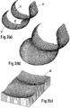
- FIG. 3(a) A typical femoral component in accordance with the invention is shown in Figure 3(a).
- the condylar surfaces 31 resemble the anatomical, especially in the sagittal view, and there is a cut-out or slot 32 for one or both cruciate ligaments.
- a patella groove 33 is continuous down to the cut-out 32 after which it splits.
- the larger femoral component in Figure 3(b) now has continuous surfaces throughout, including the patella groove, but is otherwise the same. Such a configuration requires resection of both cruciate ligaments.
- the femoral shape is then used to computer-generate a tibial surface 35, based on input laxity requirements in anterior-posterior displacement and internal-external rotation.
- a computerised method of generating tibial surfaces is described in US Patent No. 4822365.
- the new femoral shape has two advantages. First, the contact on the tibial surface can now be spread over the entire width of the tibial surface, thus increasing the contact area. Second, the patella has a continuous track, and can maintain a broad contact area throughout motion, without a split of the contacts at higher flexion. However, there is still the disadvantage that the radius of curvature of the distal femur is greater than the posterior, such that once flexion is initiated, the smaller femoral radius contacts the tibia giving a reduction in contact area.
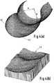
- Figures 4(a) and 4(b) shows one solution to this problem.
- the radius of the posterior portion 41 of the femoral component has been carried round to the distal femur 42.
- a surface computer-generated with this component is clearly more dished than the previous component and provides an increase in the contact area throughout.
- the reduction in the contact stresses are calculated to be significant.
- Another benefit of the new surfaces is the enhanced stability.
- the surfaces of Figure 3 it can be imagined that the flexed femur can slide forwards on the tibia with relatively little resistance.
- the anterior sliding is much more restricted because of the steeper slope of the anterior tibial surface.
- the above design form in accordance with the invention is most suitable when the anterior and posterior cruciate ligaments are resected.
- anterior-posterior laxity approximately 5 mm total
- rotational laxity (+ - 12 degrees
- Such laxity will also be sufficient for activities of everyday living.
- the disadvantage is that the components are relied upon for stability, and in the long run, this may lead to problems with the fixation of the components to the bone.
- resection of the cruciates is believed to reduce the proprioceptive response of the knee to the femoral component in the sagittal plane is within 10 degrees ( Figure 5(b) and 5(c)).
- the above design form in accordance with the invention is most suitable when the anterior and posterior cruciate ligaments are resected.
- anterior-posterior laxity approximately 5 mm total
- rotational laxity (+ - 12 degrees
- Such laxity will also be sufficient for activities of everyday living.
- the disadvantage is that the components are relied upon for stability, and in the long run, this may lead to problems with the fixation of the components to the bone.
- resection of the cruciates is believed to reduce the proprioceptive response of the knee with consequent compensatory gait patterns.
- a further disadvantage is that extremes of motion which occur during more demanding activities may be restricted, a possible disadvantage to younger or active patients.
- One further improvement provided by the present invention is to provide for sufficient anterior-posterior and rotational stability so that the prosthesis can be used with or without the cruciate ligaments, and to provide complete femoral-tibial conformity throughout the entire range of flexion.
- it consists of making the polished metal platform for supporting the plastic bearing piece or pieces concave when seen in the sagittal view. The effect will be to offer steadily increasing resistance to displacement away from the neutral position.
- the stability and laxity characteristics can be made similar to that of a normal knee, or to a usual type of condylar prosthesis.
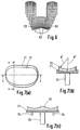
- Figure 7(a) shows the overall arrangement seen in plan view, with a metal plate or platform 71, for attachment to the tibia, having a polished cylindrical surface on the top of the plate and a plastic bearing component 72 which slides on the polished surface.
- the femoral condylar surfaces are intended to have a constant sagittal radius in the region which articulates against the plastic surface, and conform closely with the tibial surface in both frontal and sagittal planes.
- An important feature is that the radius of the plastic surface is smaller than that of the cylindrical surface.
- the cylindrical shape of the bearing surfaces is shown in Figure 7(b) in which R 2 is greater than R 2 .
- Figure 7(c) shows the medial-lateral section and a central fixation peg 73 and anti-rotation pegs 74 to prevent the platform 71 rotating on the tibia.
- FIG. 8(a) and 8(b) The metal platform 81 supports a plastics bearing component 81 which is guided for anterior-posterior motion on a rail 83 fixed or integral with the platform 81.
- the platform may be curved in the sagittal plane as shown in Figure 7(b) or be planar.
- anterior-posterior motion may be convenient to constrain anterior-posterior motion within limits by providing suitable stops, e.g by means of an upstanding post 84 secured to the platform and an elongated hole 85 in the bearing pad 82.
- the pad 82 may move freely in an anterior-posterior direction into the post 84 abutting one of the ends of the elongated hole.
- An alternative method of providing stops is indicated in dotted lines in Figure 8(a) in which the recess in the plastics meniscus component 82 has a wall 86 against which the end face of the rail 83 abuts to limit the anterior-posterior movement in one direction.
- Figure 9 is a view similar to Figure 7(c).
- a tibial bearing pad 101 is supported for sliding anterior-posterior motion on platform 103.
- the pad 101 is trapped and guided by rail 102 having a 'T'-shaped profile section.
- Figure 9 also shows an alternative trapping and guidance means by lateral guides 104 having inwardly turned projections 105 which engage in slots in the plastics pad.
- a central guide rail is preferred since this is less prone to jamming.
- the femoral components and tibial metal platform are made from a metal acceptable for use for implantation in the human body.
- a metal acceptable for use for implantation in the human body examples are cobalt-chromium and titanium alloys and stainless steels.
- the artificial patella (where present) and/or the plastics bearing components may be made from any biocompatible material capable of withstanding the imposed loads and providing appropriate bearing properties when in contact with a polished metal surface.
- the plastics material should exhibit low friction properties under these conditions.
- suitable materials are ultra-high molecular weight polyethylene or acetal copolymers.
Landscapes
- Health & Medical Sciences (AREA)
- Orthopedic Medicine & Surgery (AREA)
- Heart & Thoracic Surgery (AREA)
- Vascular Medicine (AREA)
- Oral & Maxillofacial Surgery (AREA)
- Transplantation (AREA)
- Engineering & Computer Science (AREA)
- Biomedical Technology (AREA)
- Physical Education & Sports Medicine (AREA)
- Cardiology (AREA)
- Life Sciences & Earth Sciences (AREA)
- Animal Behavior & Ethology (AREA)
- General Health & Medical Sciences (AREA)
- Public Health (AREA)
- Veterinary Medicine (AREA)
- Prostheses (AREA)
- Materials For Medical Uses (AREA)
- Steroid Compounds (AREA)
Claims (11)
- Prothèse du genou qui comprend :un composant fémoral (20) comportant deux surfaces de support condylien (31) ayant chacune une portion antérieure (45), une portion postérieure (41) avec entre-elles, un point le plus distal (42),un composant tibial (71, 81, 103) et un composant support méniscal en une seule pièce (72,82,101) entre les composants fémoral et tibial, ledit composant support méniscal présentant des dépressions concaves afin de recevoir lesdites surfaces de support condylien et des moyens de guidage (83, 84,102), sur ledit composant tibial venant en prise avec le composant méniscal afin de guider le composant support méniscal sur le composant tibial pour un déplacement de glissement dans une trajectoire sensiblement limitée à un axe antérieur-postérieur, dans laquelle les surfaces de support de chaque condyle fémoral et leur dépression concave correspondante dans le composant méniscal présentent un rayon sensiblement commun depuis le postérieur jusqu'à un point plus antérieur que le point le plus distal, lorsque l'on observe dans une pluralité de directions sagittales et les surfaces de support dans les sections sagittales respectives des composants supports fémoral et menisque étant continues du postérieur vers l'antérieur, afin que le contact entre les composants fémoral et méniscal soit maintenu sur une largeur substantielle dans la direction latérale-médiane des surfaces de support condylien sur tout le domaine de flexion.
- Prothèse selon la revendication 1 dans laquelle le composant fémoral est conformé dans ladite portion antérieure de façon à définir une rainure de rotule (53) destinée à recevoir une rotule anatomique ou artificielle (23), ladite rainure ayant une forme de section droite qui correspond à celle d'une rotule, afin qu'une rotule puisse glisser au contact de la rainure de rotule lors de la flexion de ladite prothèse entre 0 et 90°.
- Prothèse selon la revendication 1 ou 2 dans laquelle le composant tibial comprend une plate-forme métallique comportant un composant support méniscal en matière plastique supporté par cette plate-forme, ladite plate-forme métallique présentant une surface concave dirigée vers le haut et ledit composant support méniscal ayant une surface de support dont la courbure correspond sensiblement à la surface concave dirigée vers le haut de ladite plate-forme métallique et dans laquelle la courbure de ladite surface concave dirigée vers le haut et de ladite surface support est située sur un cylindre dont l'axe s'étend selon une ligne latérale-médiane.
- Prothèse selon la revendication 3 dans laquelle ledit cylindre présente un rayon (R2 ) qui est au moins aussi important que les rayons sagittaux de la surface de support condylien.
- Prothèse selon la revendication 1 dans laquelle le composant tibial comprend une plate-forme métallique et dans laquelle le mouvement de glissement du composant support méniscal par rapport à la plate-forme métallique est limité à une direction antérieure-postérieure par des moyens de guidage sur ladite plate-forme métallique.
- Prothèse selon la revendication 5 dans laquelle les moyens de guidage comprennent un épaulement (83,94,102) formé sur la plate-forme métallique, qui s'étend dans la direction antérieure-postérieure et qui coopère avec le composant méniscal.
- Prothèse selon la revendication 1 dans laquelle le composant tibial comprend une plate-forme métallique et lesdits moyens de guidage comprennent un élément en forme de rail (102) fixé à la plate-forme métallique et qui s'étend dans la direction antérieure-postérieure.
- Prothèse selon la revendication 7 dans laquelle l'élément en forme de rail s'étend entre les parties condiliennes latérale et médiane du composant fémoral.
- Prothèse selon la revendication 7 ou 8 dans laquelle l'élément en forme de rail présente en section droite sensiblement la forme d'un T et vient en prise dans des fentes qui sont prévues dans le composant support méniscal afin que l'élément en forme de rail guide et piège l'élément méniscal sur le composant tibial.
- Prothèse selon la revendication 5 dans laquelle les moyens de guidage comprennent des butées qui imitent l'amplitude du mouvement de glissement dudit composant support méniscal dans une direction antérieure ou postérieure.
- Prothèse selon la revendication 10 dans laquelle les butées comprennent une broche faisant saillie vers le haut dudit rail et venant en prise dans une fente du composant support méniscal.
Priority Applications (1)
| Application Number | Priority Date | Filing Date | Title |
|---|---|---|---|
| EP94112332A EP0626156B1 (fr) | 1991-02-04 | 1992-01-31 | Prothèse de genou |
Applications Claiming Priority (2)
| Application Number | Priority Date | Filing Date | Title |
|---|---|---|---|
| GB919102348A GB9102348D0 (en) | 1991-02-04 | 1991-02-04 | Prosthesis for knee replacement |
| GB9102348 | 1991-02-04 |
Related Child Applications (1)
| Application Number | Title | Priority Date | Filing Date |
|---|---|---|---|
| EP94112332.5 Division-Into | 1992-01-31 |
Publications (2)
| Publication Number | Publication Date |
|---|---|
| EP0498586A1 EP0498586A1 (fr) | 1992-08-12 |
| EP0498586B1 true EP0498586B1 (fr) | 1997-01-08 |
Family
ID=10689495
Family Applications (2)
| Application Number | Title | Priority Date | Filing Date |
|---|---|---|---|
| EP94112332A Expired - Lifetime EP0626156B1 (fr) | 1991-02-04 | 1992-01-31 | Prothèse de genou |
| EP92300878A Expired - Lifetime EP0498586B1 (fr) | 1991-02-04 | 1992-01-31 | Prothèse d'articulation du genou |
Family Applications Before (1)
| Application Number | Title | Priority Date | Filing Date |
|---|---|---|---|
| EP94112332A Expired - Lifetime EP0626156B1 (fr) | 1991-02-04 | 1992-01-31 | Prothèse de genou |
Country Status (6)
| Country | Link |
|---|---|
| US (1) | US5330533A (fr) |
| EP (2) | EP0626156B1 (fr) |
| AT (2) | ATE147252T1 (fr) |
| DE (2) | DE69216437T2 (fr) |
| ES (2) | ES2105441T3 (fr) |
| GB (1) | GB9102348D0 (fr) |
Cited By (1)
| Publication number | Priority date | Publication date | Assignee | Title |
|---|---|---|---|---|
| US6413279B1 (en) | 1999-03-01 | 2002-07-02 | Biomet, Inc. | Floating bearing knee joint prosthesis with a fixed tibial post |
Families Citing this family (136)
| Publication number | Priority date | Publication date | Assignee | Title |
|---|---|---|---|---|
| GB9314839D0 (en) * | 1993-07-16 | 1993-09-01 | Walker Peter S | Prosthesis for knee replacement |
| US5609639A (en) * | 1991-02-04 | 1997-03-11 | Walker; Peter S. | Prosthesis for knee replacement |
| CH685669A5 (de) * | 1991-08-28 | 1995-09-15 | Sulzer Aktiengesellschaftprote | Kniegelenkprothese. |
| GB9125311D0 (en) * | 1991-11-28 | 1992-01-29 | Biomet Ltd | Prosthetic components |
| DE4202717C1 (fr) * | 1991-12-11 | 1993-06-17 | Dietmar Prof. Dr. 3350 Kreiensen De Kubein-Meesenburg | |
| FR2699399A1 (fr) * | 1992-12-17 | 1994-06-24 | Luer Sa | Prothèse du genou bicompartimentale. |
| US5358530A (en) * | 1993-03-29 | 1994-10-25 | Zimmer, Inc. | Mobile bearing knee |
| DE4310968C2 (de) * | 1993-04-03 | 1995-08-10 | Kubein Meesenburg Dietmar | Künstliches Gelenk als Endoprothese für das menschliche Kniescheiben-Gelenk |
| GB9310193D0 (en) * | 1993-05-18 | 1993-06-30 | Walker Peter S | Knee prosthesis with femoral,tibial conformity |
| GB9314832D0 (en) * | 1993-07-16 | 1993-09-01 | Walker Peter S | Prostheses for knee replacement |
| US5871541A (en) * | 1993-11-23 | 1999-02-16 | Plus Endoprothetik, Ag | System for producing a knee-joint endoprosthesis |
| EP0680292B1 (fr) * | 1993-11-23 | 1999-07-21 | Bruno E. Dr. Gerber | Systeme permettant de realiser une endoprothese pour l'articulation du genou |
| US5755802A (en) * | 1993-12-30 | 1998-05-26 | Bruno E. Gerber | Knee-joint endoprosthesis |
| FR2714819B1 (fr) * | 1994-01-10 | 1996-03-08 | Billy Jean Louis | Prothèse de genou. |
| US8603095B2 (en) | 1994-09-02 | 2013-12-10 | Puget Bio Ventures LLC | Apparatuses for femoral and tibial resection |
| US6695848B2 (en) | 1994-09-02 | 2004-02-24 | Hudson Surgical Design, Inc. | Methods for femoral and tibial resection |
| FR2726174B1 (fr) * | 1994-10-26 | 1997-04-04 | Cornic Michel | Prothese d'articulation du genou |
| US5683468A (en) * | 1995-03-13 | 1997-11-04 | Pappas; Michael J. | Mobile bearing total joint replacement |
| DE19521597A1 (de) * | 1995-06-14 | 1996-12-19 | Kubein Meesenburg Dietmar | Künstliches Gelenk, insbesondere Endoprothese zum Ersatz natürlicher Gelenke |
| US5702465A (en) * | 1996-05-13 | 1997-12-30 | Sulzer Orthopedics Inc. | Patella prosthesis having rotational and translational freedom |
| US5824100A (en) * | 1996-10-30 | 1998-10-20 | Osteonics Corp. | Knee prosthesis with increased balance and reduced bearing stress |
| US8882847B2 (en) | 2001-05-25 | 2014-11-11 | Conformis, Inc. | Patient selectable knee joint arthroplasty devices |
| US8234097B2 (en) | 2001-05-25 | 2012-07-31 | Conformis, Inc. | Automated systems for manufacturing patient-specific orthopedic implants and instrumentation |
| US8083745B2 (en) | 2001-05-25 | 2011-12-27 | Conformis, Inc. | Surgical tools for arthroplasty |
| US7468075B2 (en) | 2001-05-25 | 2008-12-23 | Conformis, Inc. | Methods and compositions for articular repair |
| US8545569B2 (en) | 2001-05-25 | 2013-10-01 | Conformis, Inc. | Patient selectable knee arthroplasty devices |
| US7534263B2 (en) | 2001-05-25 | 2009-05-19 | Conformis, Inc. | Surgical tools facilitating increased accuracy, speed and simplicity in performing joint arthroplasty |
| US9603711B2 (en) | 2001-05-25 | 2017-03-28 | Conformis, Inc. | Patient-adapted and improved articular implants, designs and related guide tools |
| US8735773B2 (en) | 2007-02-14 | 2014-05-27 | Conformis, Inc. | Implant device and method for manufacture |
| US8480754B2 (en) | 2001-05-25 | 2013-07-09 | Conformis, Inc. | Patient-adapted and improved articular implants, designs and related guide tools |
| US7618451B2 (en) | 2001-05-25 | 2009-11-17 | Conformis, Inc. | Patient selectable joint arthroplasty devices and surgical tools facilitating increased accuracy, speed and simplicity in performing total and partial joint arthroplasty |
| US8771365B2 (en) | 2009-02-25 | 2014-07-08 | Conformis, Inc. | Patient-adapted and improved orthopedic implants, designs, and related tools |
| US8556983B2 (en) | 2001-05-25 | 2013-10-15 | Conformis, Inc. | Patient-adapted and improved orthopedic implants, designs and related tools |
| US6039764A (en) * | 1997-08-18 | 2000-03-21 | Arch Development Corporation | Prosthetic knee with adjusted center of internal/external rotation |
| US6123728A (en) * | 1997-09-17 | 2000-09-26 | Smith & Nephew, Inc. | Mobile bearing knee prosthesis |
| US6053945A (en) * | 1997-09-25 | 2000-04-25 | Johnson & Johnson Professional, Inc. | Joint prosthesis having controlled rotation |
| US5951603A (en) * | 1997-09-25 | 1999-09-14 | Johnson & Johnson Professional, Inc. | Rotatable joint prosthesis with axial securement |
| US6010534A (en) * | 1997-09-25 | 2000-01-04 | Johnson & Johnson Professional, Inc. | Rotatable tibial prosthesis with keyed axial securement |
| US5957979A (en) * | 1997-12-12 | 1999-09-28 | Bristol-Myers Squibb Company | Mobile bearing knee with metal on metal interface |
| US6162253A (en) * | 1997-12-31 | 2000-12-19 | Iowa State University Research Foundation, Inc. | Total elbow arthroplasty system |
| US6660039B1 (en) | 1998-05-20 | 2003-12-09 | Smith & Nephew, Inc. | Mobile bearing knee prosthesis |
| US6428577B1 (en) | 1998-05-20 | 2002-08-06 | Smith & Nephew, Inc. | Mobile bearing knee prosthesis |
| DE19823325C1 (de) * | 1998-05-26 | 2000-03-23 | Werner Scholz | Kniegelenk-Endoprothesensystem |
| DE69941304D1 (de) | 1998-09-14 | 2009-10-01 | Univ R | Zustandsbestimmung eines gelenks und schadenvorsorge |
| US7239908B1 (en) | 1998-09-14 | 2007-07-03 | The Board Of Trustees Of The Leland Stanford Junior University | Assessing the condition of a joint and devising treatment |
| US6306171B1 (en) | 1998-12-09 | 2001-10-23 | Iowa State University Research Foundation, Inc. | Total elbow arthroplasty system |
| US6972039B2 (en) | 1999-03-01 | 2005-12-06 | Biomet, Inc. | Floating bearing knee joint prosthesis with a fixed tibial post |
| US6165223A (en) * | 1999-03-01 | 2000-12-26 | Biomet, Inc. | Floating bearing knee joint prosthesis with a fixed tibial post |
| US8066776B2 (en) * | 2001-12-14 | 2011-11-29 | Btg International Limited | Tibial component |
| US6319283B1 (en) | 1999-07-02 | 2001-11-20 | Bristol-Myers Squibb Company | Tibial knee component with a mobile bearing |
| FR2796836B1 (fr) * | 1999-07-26 | 2002-03-22 | Michel Bercovy | Nouvelle prothese du genou |
| US6217618B1 (en) | 1999-10-26 | 2001-04-17 | Bristol-Myers Squibb Company | Tibial knee component with a mobile bearing |
| US6210444B1 (en) | 1999-10-26 | 2001-04-03 | Bristol-Myers Squibb Company | Tibial knee component with a mobile bearing |
| US6210445B1 (en) | 1999-10-26 | 2001-04-03 | Bristol-Myers Squibb Company | Tibial knee component with a mobile bearing |
| AU2001257137A1 (en) * | 2000-04-21 | 2001-11-07 | Behrooz Tohidi | Wear-resistant artificial joint |
| EP1322224B1 (fr) | 2000-09-14 | 2008-11-05 | The Board Of Trustees Of The Leland Stanford Junior University | Evaluation de l'etat d'une articulation et d'une perte de cartilage |
| AU2001290888B8 (en) | 2000-09-14 | 2007-07-26 | The Board Of Trustees Of The Leland Stanford Junior University | Assessing the condition of a joint and devising treatment |
| US6558426B1 (en) | 2000-11-28 | 2003-05-06 | Medidea, Llc | Multiple-cam, posterior-stabilized knee prosthesis |
| US8062377B2 (en) | 2001-03-05 | 2011-11-22 | Hudson Surgical Design, Inc. | Methods and apparatus for knee arthroplasty |
| US7776085B2 (en) * | 2001-05-01 | 2010-08-17 | Amedica Corporation | Knee prosthesis with ceramic tibial component |
| US7695521B2 (en) | 2001-05-01 | 2010-04-13 | Amedica Corporation | Hip prosthesis with monoblock ceramic acetabular cup |
| US6770077B2 (en) | 2001-05-21 | 2004-08-03 | Nemco Medical, Ltd. | Femoral knee saw guide and method |
| CA2447694A1 (fr) | 2001-05-25 | 2002-12-05 | Imaging Therapeutics, Inc. | Methodes et compositions d'arthroplastie |
| US9308091B2 (en) | 2001-05-25 | 2016-04-12 | Conformis, Inc. | Devices and methods for treatment of facet and other joints |
| US8951260B2 (en) | 2001-05-25 | 2015-02-10 | Conformis, Inc. | Surgical cutting guide |
| US8439926B2 (en) | 2001-05-25 | 2013-05-14 | Conformis, Inc. | Patient selectable joint arthroplasty devices and surgical tools |
| AU2002324443A1 (en) * | 2001-06-14 | 2003-01-02 | Amedica Corporation | Metal-ceramic composite articulation |
| WO2003071961A1 (fr) * | 2002-02-26 | 2003-09-04 | Nemcomed Ltd. | Guide de resection de la rotule |
| US7172596B2 (en) * | 2002-03-05 | 2007-02-06 | Coon Thomas M | Minimally invasive total knee arthroplasty method and instrumentation |
| DE10225217A1 (de) * | 2002-06-06 | 2003-12-18 | Klaus Draenert | Implantat und Anordnung zum insbesondere partiellen Ersatz von belasteten Flächen |
| CA2501041A1 (fr) | 2002-10-07 | 2004-04-22 | Conformis, Inc. | Implant articulaire par chirurgie non effractive a geometrie tridimensionnelle correspondant aux surfaces articulaires |
| EP1558181B1 (fr) | 2002-11-07 | 2015-08-26 | ConforMIS, Inc. | Procedes pour determiner les dimensions et formes de menisques, et pour mettre au point un traitement |
| EP1572042A4 (fr) * | 2002-12-17 | 2010-12-08 | Amedica Corp | Prothese discale complete |
| CA2511216C (fr) | 2002-12-20 | 2011-02-01 | Smith & Nephew, Inc. | Protheses du genou a hautes performances |
| US20040153066A1 (en) * | 2003-02-03 | 2004-08-05 | Coon Thomas M. | Apparatus for knee surgery and method of use |
| US7708782B2 (en) | 2003-07-17 | 2010-05-04 | Exactech, Inc. | Mobile bearing knee prosthesis |
| ES2343007T3 (es) | 2003-07-17 | 2010-07-21 | Exactech, Inc. | Protesis de rodilla con apoyo movil. |
| AU2004281743B2 (en) | 2003-10-17 | 2011-06-09 | Smith & Nephew, Inc. | High flexion articular insert |
| EP1525862A3 (fr) * | 2003-10-21 | 2005-12-28 | Königsee Implantate und Instrumente zur Ostheosynthese GmbH | Plaque de base tibiale pour une endoprothèse de genou. |
| DE10361780B4 (de) * | 2003-10-21 | 2008-11-13 | Königsee Implantate und Instrumente zur Osteosynthese GmbH | Tibiaplateaukomponente für eine Knieendoprothese |
| US20060030854A1 (en) | 2004-02-02 | 2006-02-09 | Haines Timothy G | Methods and apparatus for wireplasty bone resection |
| US8021368B2 (en) | 2004-01-14 | 2011-09-20 | Hudson Surgical Design, Inc. | Methods and apparatus for improved cutting tools for resection |
| US20060015115A1 (en) | 2004-03-08 | 2006-01-19 | Haines Timothy G | Methods and apparatus for pivotable guide surfaces for arthroplasty |
| US8114083B2 (en) | 2004-01-14 | 2012-02-14 | Hudson Surgical Design, Inc. | Methods and apparatus for improved drilling and milling tools for resection |
| US7435448B2 (en) * | 2004-02-06 | 2008-10-14 | Hewlett-Packard Development Company, L.P. | Sulfur-containing inorganic media coatings for ink-jet applications |
| DE102004037877B4 (de) * | 2004-08-04 | 2010-04-29 | Bauerfeind Ag | Fußprothese |
| US8292964B2 (en) * | 2005-12-14 | 2012-10-23 | New York University | Surface guided knee replacement |
| US8211181B2 (en) * | 2005-12-14 | 2012-07-03 | New York University | Surface guided knee replacement |
| GB0526385D0 (en) | 2005-12-28 | 2006-02-08 | Mcminn Derek J W | Improvements in or relating to knee prosthesis |
| US8623026B2 (en) | 2006-02-06 | 2014-01-07 | Conformis, Inc. | Patient selectable joint arthroplasty devices and surgical tools incorporating anatomical relief |
| AU2007212033B2 (en) | 2006-02-06 | 2014-01-23 | Conformis, Inc. | Patient selectable joint arthroplasty devices and surgical tools |
| WO2007108804A1 (fr) | 2006-03-21 | 2007-09-27 | Komistek Richard D | Prothèses d'arthroplastie totale à moments induits |
| EP2043561B1 (fr) * | 2006-06-30 | 2016-01-27 | Smith & Nephew, Inc. | Prothèse articulée pour un mouvement anatomique |
| US20080097450A1 (en) * | 2006-09-14 | 2008-04-24 | Zimmer Technology, Inc. | Patella clamp |
| WO2008101090A2 (fr) | 2007-02-14 | 2008-08-21 | Conformis, Inc. | Dispositif d'implant et procédé de fabrication |
| DE102007056141B4 (de) | 2007-11-19 | 2020-04-23 | Ohst Medizintechnik Ag | Tibia Insert |
| US8292965B2 (en) * | 2008-02-11 | 2012-10-23 | New York University | Knee joint with a ramp |
| WO2009111626A2 (fr) | 2008-03-05 | 2009-09-11 | Conformis, Inc. | Implants pour modifier des modèles d’usure de surfaces articulaires |
| CN102076283B (zh) * | 2008-06-24 | 2014-03-26 | 彼得·斯坦利·沃克 | 凹窝斜坡膝关节假体 |
| US8187335B2 (en) | 2008-06-30 | 2012-05-29 | Depuy Products, Inc. | Posterior stabilized orthopaedic knee prosthesis having controlled condylar curvature |
| US9119723B2 (en) | 2008-06-30 | 2015-09-01 | Depuy (Ireland) | Posterior stabilized orthopaedic prosthesis assembly |
| US8236061B2 (en) | 2008-06-30 | 2012-08-07 | Depuy Products, Inc. | Orthopaedic knee prosthesis having controlled condylar curvature |
| US8192498B2 (en) | 2008-06-30 | 2012-06-05 | Depuy Products, Inc. | Posterior cructiate-retaining orthopaedic knee prosthesis having controlled condylar curvature |
| US9168145B2 (en) | 2008-06-30 | 2015-10-27 | Depuy (Ireland) | Posterior stabilized orthopaedic knee prosthesis having controlled condylar curvature |
| US8206451B2 (en) | 2008-06-30 | 2012-06-26 | Depuy Products, Inc. | Posterior stabilized orthopaedic prosthesis |
| US8828086B2 (en) * | 2008-06-30 | 2014-09-09 | Depuy (Ireland) | Orthopaedic femoral component having controlled condylar curvature |
| US7981159B2 (en) * | 2008-07-16 | 2011-07-19 | Depuy Products, Inc. | Antero-posterior placement of axis of rotation for a rotating platform |
| US8202323B2 (en) * | 2008-07-16 | 2012-06-19 | Depuy Products, Inc. | Knee prostheses with enhanced kinematics |
| US8808303B2 (en) | 2009-02-24 | 2014-08-19 | Microport Orthopedics Holdings Inc. | Orthopedic surgical guide |
| US9017334B2 (en) | 2009-02-24 | 2015-04-28 | Microport Orthopedics Holdings Inc. | Patient specific surgical guide locator and mount |
| US8808297B2 (en) | 2009-02-24 | 2014-08-19 | Microport Orthopedics Holdings Inc. | Orthopedic surgical guide |
| BRPI1014917A2 (pt) | 2009-04-16 | 2016-04-19 | Conformis Inc | "dispositivos de artroplastia de junta específica para páciente para reparo de ligamento" |
| US8915965B2 (en) | 2009-05-07 | 2014-12-23 | Depuy (Ireland) | Anterior stabilized knee implant |
| EP2272466A1 (fr) | 2009-07-10 | 2011-01-12 | Medizinische Hochschule Hannover | Prothèse du genou et procédé de fabrication |
| US8906105B2 (en) | 2009-08-11 | 2014-12-09 | Michael D. Ries | Systems and methods for mobile bearing prosthetic knee |
| US9095453B2 (en) * | 2009-08-11 | 2015-08-04 | Michael D. Ries | Position adjustable trial systems for prosthetic implants |
| US8568485B2 (en) * | 2009-08-11 | 2013-10-29 | Imds Corporation | Articulating trials for prosthetic implants |
| US8382848B2 (en) * | 2009-08-11 | 2013-02-26 | Imds Corporation | Position adjustable trial systems for prosthetic implants |
| US8998997B2 (en) | 2009-08-11 | 2015-04-07 | Michael D. Ries | Implantable mobile bearing prosthetics |
| US8496666B2 (en) | 2009-08-11 | 2013-07-30 | Imds Corporation | Instrumentation for mobile bearing prosthetics |
| AU2010327987B2 (en) | 2009-12-11 | 2015-04-02 | Conformis, Inc. | Patient-specific and patient-engineered orthopedic implants |
| EP2528546B1 (fr) | 2010-01-29 | 2018-07-25 | Smith & Nephew, Inc. | Prothèse de genou à préservation des deux ligaments croisés |
| US8308808B2 (en) | 2010-02-19 | 2012-11-13 | Biomet Manufacturing Corp. | Latent mobile bearing for prosthetic device |
| EP2595571B1 (fr) | 2010-07-23 | 2015-09-09 | Michael D. Ries | Systèmes pour genou prosthétique |
| US8926709B2 (en) | 2010-08-12 | 2015-01-06 | Smith & Nephew, Inc. | Structures for use in orthopaedic implant fixation and methods of installation onto a bone |
| US8747410B2 (en) | 2010-10-26 | 2014-06-10 | Zimmer, Inc. | Patellar resection instrument with variable depth guide |
| AU2012217654B2 (en) | 2011-02-15 | 2016-09-22 | Conformis, Inc. | Patient-adapted and improved articular implants, procedures and tools to address, assess, correct, modify and/or accommodate anatomical variation and/or asymmetry |
| US8409293B1 (en) | 2011-10-26 | 2013-04-02 | Sevika Holding AG | Knee prosthesis |
| US8702803B2 (en) | 2011-12-29 | 2014-04-22 | Mako Surgical Corp. | Locking assembly for tibial prosthesis component |
| US9486226B2 (en) | 2012-04-18 | 2016-11-08 | Conformis, Inc. | Tibial guides, tools, and techniques for resecting the tibial plateau |
| US20130317523A1 (en) * | 2012-05-22 | 2013-11-28 | Todd Borus | Total Knee Arthroplasty Apparatus and Method of Use |
| US9675471B2 (en) | 2012-06-11 | 2017-06-13 | Conformis, Inc. | Devices, techniques and methods for assessing joint spacing, balancing soft tissues and obtaining desired kinematics for joint implant components |
| CN105392450B (zh) | 2013-03-15 | 2017-09-29 | 马科外科公司 | 胫骨膝关节单髁植入物 |
| US10179052B2 (en) | 2016-07-28 | 2019-01-15 | Depuy Ireland Unlimited Company | Total knee implant prosthesis assembly and method |
| JP2020500600A (ja) | 2016-11-30 | 2020-01-16 | ジー リン ラスムッセン | 脛骨ベースプレートを提供するためのシステムおよび方法 |
| EP3412252B1 (fr) | 2017-06-09 | 2020-02-12 | Howmedica Osteonics Corp. | Structure de support d'interverrouillage de polymère |
Family Cites Families (19)
| Publication number | Priority date | Publication date | Assignee | Title |
|---|---|---|---|---|
| GB1509194A (en) * | 1974-04-22 | 1978-05-04 | Nat Res Dev | Endoprosthetic devices |
| US4085466A (en) * | 1974-11-18 | 1978-04-25 | National Research Development Corporation | Prosthetic joint device |
| US4224696A (en) * | 1978-09-08 | 1980-09-30 | Hexcel Corporation | Prosthetic knee |
| US4215439A (en) * | 1978-10-16 | 1980-08-05 | Zimmer, USA | Semi-restraining knee prosthesis |
| US4340978A (en) * | 1979-07-02 | 1982-07-27 | Biomedical Engineering Corp. | New Jersey meniscal bearing knee replacement |
| JPS6077752A (ja) * | 1983-09-30 | 1985-05-02 | 東海林 宏 | メニスカル人工膝関節 |
| DE3433264C2 (de) * | 1984-09-11 | 1986-10-02 | S + G Implants GmbH, 2400 Lübeck | Tibiateil für eine Kniegelenk-Endoprothese |
| US4673407A (en) * | 1985-02-20 | 1987-06-16 | Martin Daniel L | Joint-replacement prosthetic device |
| DE3529894A1 (de) * | 1985-08-21 | 1987-03-05 | Orthoplant Endoprothetik | Kniegelenk-endoprothese |
| US4714474A (en) * | 1986-05-12 | 1987-12-22 | Dow Corning Wright Corporation | Tibial knee joint prosthesis with removable articulating surface insert |
| US4822365A (en) * | 1986-05-30 | 1989-04-18 | Walker Peter S | Method of design of human joint prosthesis |
| US4822362A (en) * | 1987-05-19 | 1989-04-18 | Walker Peter S | Process and apparatus for tibial plateau compenent |
| GB2219942A (en) * | 1988-06-22 | 1989-12-28 | John Polyzoides | Knee prosthesis |
| US5147405A (en) * | 1990-02-07 | 1992-09-15 | Boehringer Mannheim Corporation | Knee prosthesis |
| DE4009360A1 (de) * | 1990-02-16 | 1991-08-22 | Friedrichsfeld Gmbh | Kniegelenk-endoprothese |
| GB9005496D0 (en) * | 1990-03-12 | 1990-05-09 | Howmedica | Tibial component for a replacement knee prosthesis and total knee prosthesis incorporating such a component |
| US5116375A (en) * | 1990-08-27 | 1992-05-26 | Hofmann Aaron A | Knee prosthesis |
| GB9102633D0 (en) * | 1991-02-07 | 1991-03-27 | Finsbury Instr Ltd | Knee prosthesis |
| US5133758A (en) * | 1991-09-16 | 1992-07-28 | Research And Education Institute, Inc. Harbor-Ucla Medical Center | Total knee endoprosthesis with fixed flexion-extension axis of rotation |
-
1991
- 1991-02-04 GB GB919102348A patent/GB9102348D0/en active Pending
-
1992
- 1992-01-31 DE DE69216437T patent/DE69216437T2/de not_active Expired - Lifetime
- 1992-01-31 ES ES94112332T patent/ES2105441T3/es not_active Expired - Lifetime
- 1992-01-31 EP EP94112332A patent/EP0626156B1/fr not_active Expired - Lifetime
- 1992-01-31 DE DE69221162T patent/DE69221162T2/de not_active Expired - Lifetime
- 1992-01-31 AT AT92300878T patent/ATE147252T1/de not_active IP Right Cessation
- 1992-01-31 AT AT94112332T patent/ATE155667T1/de not_active IP Right Cessation
- 1992-01-31 EP EP92300878A patent/EP0498586B1/fr not_active Expired - Lifetime
- 1992-01-31 ES ES92300878T patent/ES2096024T3/es not_active Expired - Lifetime
- 1992-02-03 US US07/829,369 patent/US5330533A/en not_active Expired - Lifetime
Cited By (1)
| Publication number | Priority date | Publication date | Assignee | Title |
|---|---|---|---|---|
| US6413279B1 (en) | 1999-03-01 | 2002-07-02 | Biomet, Inc. | Floating bearing knee joint prosthesis with a fixed tibial post |
Also Published As
| Publication number | Publication date |
|---|---|
| DE69216437D1 (de) | 1997-02-20 |
| EP0626156A3 (fr) | 1994-12-28 |
| US5330533A (en) | 1994-07-19 |
| EP0626156A2 (fr) | 1994-11-30 |
| GB9102348D0 (en) | 1991-03-20 |
| DE69221162T2 (de) | 1997-11-27 |
| ATE155667T1 (de) | 1997-08-15 |
| EP0626156B1 (fr) | 1997-07-23 |
| ATE147252T1 (de) | 1997-01-15 |
| ES2096024T3 (es) | 1997-03-01 |
| DE69221162D1 (de) | 1997-08-28 |
| EP0498586A1 (fr) | 1992-08-12 |
| DE69216437T2 (de) | 1997-04-24 |
| ES2105441T3 (es) | 1997-10-16 |
Similar Documents
| Publication | Publication Date | Title |
|---|---|---|
| EP0498586B1 (fr) | Prothèse d'articulation du genou | |
| US5609639A (en) | Prosthesis for knee replacement | |
| EP0634155B1 (fr) | Prothèse de remplacement du genou | |
| US10383738B2 (en) | Tibial component | |
| US5935173A (en) | Knee prosthesis | |
| US5997577A (en) | Knee joint prosthesis | |
| US5011496A (en) | Prosthetic joint | |
| US5723016A (en) | Implantable prosthetic patellar components | |
| US4888021A (en) | Knee and patellar prosthesis | |
| US7060101B2 (en) | Tibial component | |
| EP0021421B1 (fr) | Endoprothèse d'articulation | |
| US20170071758A1 (en) | Femoral extension prosthetic component and tibial shelf prosthetic component for unicondylar meniscal bearing knee prosthesis and prosthesis including such a component | |
| GB2277034A (en) | Implantable prosthetic patellar component | |
| AU707766B2 (en) | Knee prosthesis | |
| AU714764B2 (en) | Knee prosthesis |
Legal Events
| Date | Code | Title | Description |
|---|---|---|---|
| PUAI | Public reference made under article 153(3) epc to a published international application that has entered the european phase |
Free format text: ORIGINAL CODE: 0009012 |
|
| AK | Designated contracting states |
Kind code of ref document: A1 Designated state(s): AT BE CH DE DK ES FR GB GR IT LI LU MC NL PT SE |
|
| 17P | Request for examination filed |
Effective date: 19920908 |
|
| 17Q | First examination report despatched |
Effective date: 19940120 |
|
| GRAG | Despatch of communication of intention to grant |
Free format text: ORIGINAL CODE: EPIDOS AGRA |
|
| GRAH | Despatch of communication of intention to grant a patent |
Free format text: ORIGINAL CODE: EPIDOS IGRA |
|
| GRAH | Despatch of communication of intention to grant a patent |
Free format text: ORIGINAL CODE: EPIDOS IGRA |
|
| GRAA | (expected) grant |
Free format text: ORIGINAL CODE: 0009210 |
|
| AK | Designated contracting states |
Kind code of ref document: B1 Designated state(s): AT BE CH DE DK ES FR GB GR IT LI LU MC NL PT SE |
|
| PG25 | Lapsed in a contracting state [announced via postgrant information from national office to epo] |
Ref country code: DK Effective date: 19970108 Ref country code: GR Free format text: LAPSE BECAUSE OF FAILURE TO SUBMIT A TRANSLATION OF THE DESCRIPTION OR TO PAY THE FEE WITHIN THE PRESCRIBED TIME-LIMIT Effective date: 19970108 |
|
| REF | Corresponds to: |
Ref document number: 147252 Country of ref document: AT Date of ref document: 19970115 Kind code of ref document: T |
|
| XX | Miscellaneous (additional remarks) |
Free format text: TEILANMELDUNG 94112332.5 EINGEREICHT AM 31/01/92. |
|
| REG | Reference to a national code |
Ref country code: CH Ref legal event code: EP Ref country code: CH Ref legal event code: NV Representative=s name: PATENTANWALTSBUREAU R. A. MASPOLI |
|
| PGFP | Annual fee paid to national office [announced via postgrant information from national office to epo] |
Ref country code: MC Payment date: 19970121 Year of fee payment: 6 |
|
| DX | Miscellaneous (deleted) | ||
| PGFP | Annual fee paid to national office [announced via postgrant information from national office to epo] |
Ref country code: DK Payment date: 19970129 Year of fee payment: 6 Ref country code: SE Payment date: 19970129 Year of fee payment: 6 |
|
| ET | Fr: translation filed | ||
| REF | Corresponds to: |
Ref document number: 69216437 Country of ref document: DE Date of ref document: 19970220 |
|
| REG | Reference to a national code |
Ref country code: ES Ref legal event code: FG2A Ref document number: 2096024 Country of ref document: ES Kind code of ref document: T3 |
|
| ITF | It: translation for a ep patent filed |
Owner name: 0403;06MIFING. C. GREGORJ S.P.A. |
|
| PGFP | Annual fee paid to national office [announced via postgrant information from national office to epo] |
Ref country code: LU Payment date: 19970327 Year of fee payment: 6 |
|
| PG25 | Lapsed in a contracting state [announced via postgrant information from national office to epo] |
Ref country code: PT Effective date: 19970408 Ref country code: SE Effective date: 19970408 |
|
| PLBE | No opposition filed within time limit |
Free format text: ORIGINAL CODE: 0009261 |
|
| STAA | Information on the status of an ep patent application or granted ep patent |
Free format text: STATUS: NO OPPOSITION FILED WITHIN TIME LIMIT |
|
| 26N | No opposition filed | ||
| PG25 | Lapsed in a contracting state [announced via postgrant information from national office to epo] |
Ref country code: LU Free format text: LAPSE BECAUSE OF NON-PAYMENT OF DUE FEES Effective date: 19980131 |
|
| PG25 | Lapsed in a contracting state [announced via postgrant information from national office to epo] |
Ref country code: MC Free format text: LAPSE BECAUSE OF NON-PAYMENT OF DUE FEES Effective date: 19980731 |
|
| REG | Reference to a national code |
Ref country code: GB Ref legal event code: IF02 |
|
| PGFP | Annual fee paid to national office [announced via postgrant information from national office to epo] |
Ref country code: AT Payment date: 20030121 Year of fee payment: 12 |
|
| PG25 | Lapsed in a contracting state [announced via postgrant information from national office to epo] |
Ref country code: AT Free format text: LAPSE BECAUSE OF NON-PAYMENT OF DUE FEES Effective date: 20040131 |
|
| PGFP | Annual fee paid to national office [announced via postgrant information from national office to epo] |
Ref country code: BE Payment date: 20050125 Year of fee payment: 14 |
|
| PGFP | Annual fee paid to national office [announced via postgrant information from national office to epo] |
Ref country code: NL Payment date: 20050131 Year of fee payment: 14 |
|
| PG25 | Lapsed in a contracting state [announced via postgrant information from national office to epo] |
Ref country code: BE Free format text: LAPSE BECAUSE OF NON-PAYMENT OF DUE FEES Effective date: 20060131 |
|
| PG25 | Lapsed in a contracting state [announced via postgrant information from national office to epo] |
Ref country code: NL Free format text: LAPSE BECAUSE OF NON-PAYMENT OF DUE FEES Effective date: 20060801 |
|
| NLV4 | Nl: lapsed or anulled due to non-payment of the annual fee |
Effective date: 20060801 |
|
| BERE | Be: lapsed |
Owner name: *WALKER PETER STANLEY Effective date: 20060131 |
|
| PGFP | Annual fee paid to national office [announced via postgrant information from national office to epo] |
Ref country code: CH Payment date: 20100125 Year of fee payment: 19 Ref country code: ES Payment date: 20100126 Year of fee payment: 19 |
|
| PGFP | Annual fee paid to national office [announced via postgrant information from national office to epo] |
Ref country code: FR Payment date: 20100205 Year of fee payment: 19 Ref country code: IT Payment date: 20100128 Year of fee payment: 19 |
|
| PGFP | Annual fee paid to national office [announced via postgrant information from national office to epo] |
Ref country code: DE Payment date: 20100127 Year of fee payment: 19 Ref country code: GB Payment date: 20100125 Year of fee payment: 19 |
|
| REG | Reference to a national code |
Ref country code: CH Ref legal event code: PL |
|
| GBPC | Gb: european patent ceased through non-payment of renewal fee |
Effective date: 20110131 |
|
| REG | Reference to a national code |
Ref country code: FR Ref legal event code: ST Effective date: 20110930 |
|
| PG25 | Lapsed in a contracting state [announced via postgrant information from national office to epo] |
Ref country code: LI Free format text: LAPSE BECAUSE OF NON-PAYMENT OF DUE FEES Effective date: 20110131 Ref country code: CH Free format text: LAPSE BECAUSE OF NON-PAYMENT OF DUE FEES Effective date: 20110131 Ref country code: FR Free format text: LAPSE BECAUSE OF NON-PAYMENT OF DUE FEES Effective date: 20110131 |
|
| PG25 | Lapsed in a contracting state [announced via postgrant information from national office to epo] |
Ref country code: GB Free format text: LAPSE BECAUSE OF NON-PAYMENT OF DUE FEES Effective date: 20110131 |
|
| PG25 | Lapsed in a contracting state [announced via postgrant information from national office to epo] |
Ref country code: IT Free format text: LAPSE BECAUSE OF NON-PAYMENT OF DUE FEES Effective date: 20110131 |
|
| REG | Reference to a national code |
Ref country code: ES Ref legal event code: FD2A Effective date: 20120220 |
|
| REG | Reference to a national code |
Ref country code: DE Ref legal event code: R119 Ref document number: 69216437 Country of ref document: DE Effective date: 20110802 |
|
| PG25 | Lapsed in a contracting state [announced via postgrant information from national office to epo] |
Ref country code: ES Free format text: LAPSE BECAUSE OF NON-PAYMENT OF DUE FEES Effective date: 20110201 |
|
| PG25 | Lapsed in a contracting state [announced via postgrant information from national office to epo] |
Ref country code: DE Free format text: LAPSE BECAUSE OF NON-PAYMENT OF DUE FEES Effective date: 20110802 |