EP0498322B1 - Vorrichtung zum abgedichteten Verbinden der glattzylindrischen Enden zweier Rohre - Google Patents
Vorrichtung zum abgedichteten Verbinden der glattzylindrischen Enden zweier Rohre Download PDFInfo
- Publication number
- EP0498322B1 EP0498322B1 EP92101683A EP92101683A EP0498322B1 EP 0498322 B1 EP0498322 B1 EP 0498322B1 EP 92101683 A EP92101683 A EP 92101683A EP 92101683 A EP92101683 A EP 92101683A EP 0498322 B1 EP0498322 B1 EP 0498322B1
- Authority
- EP
- European Patent Office
- Prior art keywords
- sealing sleeve
- sealing
- pipes
- edge
- clamp hoop
- Prior art date
- Legal status (The legal status is an assumption and is not a legal conclusion. Google has not performed a legal analysis and makes no representation as to the accuracy of the status listed.)
- Expired - Lifetime
Links
- 238000007789 sealing Methods 0.000 claims abstract description 90
- 230000002093 peripheral effect Effects 0.000 claims description 11
- 230000008602 contraction Effects 0.000 claims description 3
- 230000003247 decreasing effect Effects 0.000 claims 1
- 239000011324 bead Substances 0.000 abstract description 22
- 239000000463 material Substances 0.000 abstract description 5
- 230000004323 axial length Effects 0.000 description 2
- 230000008878 coupling Effects 0.000 description 2
- 238000010168 coupling process Methods 0.000 description 2
- 238000005859 coupling reaction Methods 0.000 description 2
- 229910001018 Cast iron Inorganic materials 0.000 description 1
- 229910001208 Crucible steel Inorganic materials 0.000 description 1
- 230000015572 biosynthetic process Effects 0.000 description 1
- 230000000694 effects Effects 0.000 description 1
- 239000013013 elastic material Substances 0.000 description 1
- 239000013536 elastomeric material Substances 0.000 description 1
- 230000002349 favourable effect Effects 0.000 description 1
- 239000010865 sewage Substances 0.000 description 1
- 229910001220 stainless steel Inorganic materials 0.000 description 1
- 239000010935 stainless steel Substances 0.000 description 1
- 239000010959 steel Substances 0.000 description 1
Images

Classifications
-
- F—MECHANICAL ENGINEERING; LIGHTING; HEATING; WEAPONS; BLASTING
- F16—ENGINEERING ELEMENTS AND UNITS; GENERAL MEASURES FOR PRODUCING AND MAINTAINING EFFECTIVE FUNCTIONING OF MACHINES OR INSTALLATIONS; THERMAL INSULATION IN GENERAL
- F16L—PIPES; JOINTS OR FITTINGS FOR PIPES; SUPPORTS FOR PIPES, CABLES OR PROTECTIVE TUBING; MEANS FOR THERMAL INSULATION IN GENERAL
- F16L17/00—Joints with packing adapted to sealing by fluid pressure
- F16L17/02—Joints with packing adapted to sealing by fluid pressure with sealing rings arranged between outer surface of pipe and inner surface of sleeve or socket
- F16L17/04—Joints with packing adapted to sealing by fluid pressure with sealing rings arranged between outer surface of pipe and inner surface of sleeve or socket with longitudinally split or divided sleeve
-
- F—MECHANICAL ENGINEERING; LIGHTING; HEATING; WEAPONS; BLASTING
- F16—ENGINEERING ELEMENTS AND UNITS; GENERAL MEASURES FOR PRODUCING AND MAINTAINING EFFECTIVE FUNCTIONING OF MACHINES OR INSTALLATIONS; THERMAL INSULATION IN GENERAL
- F16L—PIPES; JOINTS OR FITTINGS FOR PIPES; SUPPORTS FOR PIPES, CABLES OR PROTECTIVE TUBING; MEANS FOR THERMAL INSULATION IN GENERAL
- F16L21/00—Joints with sleeve or socket
- F16L21/002—Sleeves or nipples for pipes of the same diameter; Reduction pieces
- F16L21/005—Sleeves or nipples for pipes of the same diameter; Reduction pieces made of elastic material, e.g. partly or completely surrounded by clamping devices
Definitions
- the invention relates to a device for the sealed connection of the smooth cylindrical ends of two tubes.
- a pipe connection device is known from DE-PS 34 04 739.
- To increase the transverse rigidity and Improvement of the axial securing of the pipe connection are provided on both outer edges of the clamp band of this pipe coupling obliquely radially inwardly angled flanges which are pressed against the outer peripheral surfaces of the pipes to be connected when tightening the clamping screw and the resulting contraction of the clamp band and the sealing sleeve.
- the sealing sleeve of this known pipe coupling forms only one sealing area generated by the sealing lip on both sides of its radially inwardly projecting, central annular web, which can be insufficient in certain cases.
- a sealing pipe connection device in which metallic securing devices are used for axially securing the pipe ends to be connected, which are arranged on both sides of a sealing sleeve in the outer edge regions of a clamp band and connect this to the pipe ends.
- DE-OS 36 05 020 shows a pipe connection device in which the axial securing is also not realized via the sealing sleeve, but rather via metallic flanks of the clamp band engaging in the outer circumference of the pipes.
- the present invention has for its object to provide a device for the sealed connection of the smooth cylindrical ends of two pipes, which has an effective axial locking and high transverse rigidity without the clamp band forming a sound bridge between the pipes to be connected, and also the smallest possible Number of parts.
- a relatively narrow circumferential bead is provided next to each outer edge of the clamp band engages appropriately in each edge section of the sealing sleeve with a trough-shaped cross section, and the clamp band is provided with radially inwardly projecting flanges in connection with the edge-side beads, such that they overlap the outer edges of the edge sections of the sealing sleeve with a trough-shaped cross section when the clamp band is contracted, however, maintain a radial clearance with respect to the outer circumference of the connected pipes.
- the radially inwardly projecting flanges on the outside of the clamp band prevent on the one hand that the elastic material of the sealing sleeve escapes when the clamp is tensioned, but on the other hand they have radial play relative to the outer circumference of the connected pipes, which ensures that a sound bridge between the connected pipes is excluded by the clamp band.
- the improved transverse rigidity of the pipe connection ie the increased resistance of the device against angling of the pipes in the connection area, the axes of which ideally run coaxially, is achieved in that each pipe has two axially spaced ring zones opposite the central annular web of the sealing sleeve through the clamp band the sealing sleeve is held.
- One ring zone is located directly next to the annular web and is caused by the central circumferential bead of the clamp band, which fits into an annular recess on the outer circumference of the sealing collar, while the other ring zone is created by the narrow, circumferential beads on the clamp band, which engage in a respective edge section of the sealing sleeve with a trough-shaped cross section.
- the sealing collar therefore points towards each side of its central annular web, viewed in the axial direction, also three ring-shaped sealing areas, the middle sealing area being formed in each case by the ring-shaped sealing lips, the material of which, when the clamp band is tensioned, is enclosed between the central circumferential bead and the edge-side beads of the clamp band and pressed against the outer circumference of the tubes.
- the two peripheral beads of the clamp band have a greater depth than the central peripheral bead.
- edge-side beads of the clamp band and the edge sections of the sealing sleeve which receive these beads have essentially V-shaped cross-sections with a rounded base or edge.
- the edge of the sealing sleeve can be pressed strongly against the outer circumferential surface of the connecting pipes, the circular inner edge of the edge sections of the sealing sleeve, which is rounded in section, acting as if it were a segment of an O-ring.
- the edge sections of the sealing sleeve with a substantially V-shaped cross section border axially inwards on the annular sealing lips.
- the annular sealing lips of the sealing sleeve have a greater radial extension inwards than the edge sections of the sealing sleeve with an essentially V-shaped cross section.
- Yet another embodiment of the invention characterized in that the innermost sealing regions of the sealing sleeve are formed by inner wall sections which extend outward from the central web with an increasingly smaller diameter. These tapered inner wall sections of the sealing sleeve are pressed against the outer circumference of the pipes to be connected when the clamp band is tensioned through its central circumferential bead.
- Yet another embodiment of the invention is characterized in that the axial extent or width of the central peripheral bead of the clamp band is a multiple of that of the two peripheral beads.
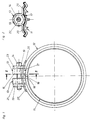
- the device shown in Fig. 1 is used for the sealed connection of the smooth cylindrical ends of two tubes 10, (Fig. 4), which, for. B. sewage pipes can be made of cast iron or steel.
- the device contains a sealing collar 11 made of elastomeric material and a clamp band 12 made of preferably stainless steel, which is used to contract the sealing collar 11.
- a clamp band 12 made of preferably stainless steel, which is used to contract the sealing collar 11.
- an essentially radially outwardly projecting clamping jaws 13 is fastened at each end of the clamp band 12 and can be pulled against one another by means of a clamping screw 14 in order to reduce the inside diameter of the clamp band 12.
- the gem Fig. 1 right jaws 13 attached to one end of the clamp band 13 so that its left edge 15 is aligned with one end 16 of the clamp band 12, while the gem.
- Fig. 1 right jaws 13 attached to one end of the clamp band 13 so that its left edge 15 is aligned with one end 16 of the clamp band 12, while the gem. Fig
- left clamping jaws 13 is arranged at a certain distance from the other end 17 of the clamp band 12 to form a bridging section 18 between the clamping jaws 13, so that the entire outer circumference of the sealing sleeve 11 is encompassed by the clamp band 12.
- the two jaws 13 are of the same design and they each have an angular bracket 19 with two fastening tabs 20.
- Fig. 1 left clamping jaw 13 is a hexagon nut with an outer collar 21 rotatably inserted, into which the threaded shaft of the clamping screw 14 is screwed.
- the threaded shaft of the clamping screw 14 also extends axially displaceably through a hexagon socket 22 with an outer collar 23, which is fitted in the angular bracket 19 of the right clamping jaw 13.
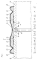
- the clamp band 12 has a centrally arranged, in the form of an arcuate flat and circumferential bead 24, which is adjoined in both directions to the outside by a flat section 25.
- Circumferential beads 26 with a substantially V-shaped cross section and rounded edge 27 adjoin these sections 25.
- the beads 26 are followed by flanges 28 projecting radially inwards.
- the sealing sleeve 11 has on its outside a cross-sectional contour that corresponds to that of the inside of the clamp band 12. This means that the bead 24 of the clamp band 12 fits into an annular recess 29 on the outer circumference of the sealing sleeve 11.
- the flat sections 25 extend over correspondingly flat sections 30 of the sealing collar 11 and the beads 26 of the clamp band 12 fit into substantially V-shaped troughs 31 of edge sections 32 of the sealing collar 11.
- the cross section of these edge sections 32 of the sealing collar 11 is overall V-shaped, its inner edge 33 being rounded.
- edge sections 32 are followed by an annular sealing lip 34 and to a certain extent Axial spacing then follows inward-tapered inner wall sections 35 with an increasingly smaller inner diameter, which end at a centrally arranged, radially inwardly projecting annular web 36.
- This web 36 serves as a stop for the front ends 330 of the tubes 10 (FIG. 4).
- the annular sealing lips 34 extend further radially inwards than the edge sections 32 with an essentially V-shaped cross section.
- the smallest inside diameter of these edge sections 32 of the sealing sleeve 11 corresponds approximately to the outside diameter of the tubes 10.
- the sealing lips 34 are bent inwards and the inclined inner wall sections 35 serve as guides for the tube ends until the ends 330 of the tubes 10 bear against the annular web 36.
- the outer diameter of the tubes 10 fluctuate within a certain tolerance range and the sealing sleeve 11 is dimensioned taking into account this tolerance range so that the ends 330 of the tubes 10 either come to lie directly in the corners 37 or somewhat radially inward from these corners 37.
- the sealing sleeve 11 is in the relaxed state in this assembly phase.
- the clamp band 12 is contracted in the circumferential direction by means of the tensioning screw 14, thereby contracting the sealing sleeve 11.
- the edge sections 32 of the sealing collar 11, the sealing lips 34 and parts of the chamfered inner wall sections 35 are pressed in the form of ring zones against the outer circumference of the pipes 10.
- the sealing collar 11 is positioned opposite both sides of the central annular web 36
- Three sealing areas A, B and C each created (FIG. 4), the axial length of which also depends on the degree of prestressing of the sealing sleeve 11 and can be set within certain limits.
- the two edge-side beads 26 of the clamp band 12 have a greater depth than the central circumferential bead 24 and the smallest inside diameter of the edge sections 32 of the sealing sleeve 11 is smaller than the smallest inside diameter of the oblique inner wall sections 35, the material of the sealing sleeve 11 becomes in the Sealing areas A pressed more than in the sealing areas C, but also more than in the sealing areas B, because the material of the sealing lips 34 can dodge axially inwards.
- the flanges 28 overlap the outer edges of the edge sections 32 so that the material of the sealing sleeve 11 cannot escape to the outside.
- the radial extension of the flanges 28 is dimensioned in such a way that when the clamp band 12 is contracted, the inner edges of the flanges 28 maintain a radial clearance with respect to the outer circumference of the tubes 10. In this way, a sound bridge through the metallic clamp band 12 from one tube 10 to the other tube 10 is avoided.
- the three sealing areas A, B, C opposite each side of the central annular web 36 improve the sealing function of this pipe connection and the strongly pressed edge sections 32 of the sealing collar 11 and ring zones in the area of the inner wall sections 35 result in increased transverse rigidity and improved axial securing in comparison with the prior art the pipe connections.
Landscapes
- Engineering & Computer Science (AREA)
- General Engineering & Computer Science (AREA)
- Mechanical Engineering (AREA)
- Physics & Mathematics (AREA)
- Fluid Mechanics (AREA)
- Flanged Joints, Insulating Joints, And Other Joints (AREA)
- Non-Disconnectible Joints And Screw-Threaded Joints (AREA)
Description
- Die Erfindung bezieht sich auf eine Vorrichtung zum abgedichteten Verbinden der glattzylindrischen Enden zweier Rohre.
- Eine Rohrverbindungsvorrichtung ist durch die DE-PS 34 04 739 bekannt. Zur Erhöhung der Quersteifigkeit und zur Verbesserung der Axialsicherung der Rohrverbindung sind an beiden Außenrändern des Schellenbandes dieser Rohrkupplung schräg radial nach innen abgewinkelte Flansche vorgesehen, die beim Anziehen der Spannschraube und der dadurch bedingten Kontraktion des Schellenbandes und der Dichtmanschette gegen die Außenumfangsflächen der zu verbindenden Rohre gedrückt werden. Dadurch ergibt sich jedoch über das metallische Schellenband eine unerwünschte Schallbrücke von Rohr zu Rohr. Außerdem bildet die Dichtmanschette dieser bekannten Rohrkupplung gegenüber beiden Seiten ihres radial nach innen ragenden, mittigen ringförmigen Stegs nur jeweils einen durch die Dichtlippe erzeugten Dichtbereich, was in gewissen Fällen ungenügend sein kann.
- Aus der DE-PS 37 10 852 ist eine abdichtende Rohrverbindungseinrichtung bekannt, bei der zur axialen Sicherung der miteinander zu verbindenden Rohrenden metallische Sicherungseinrichtungen verwendet werden, die beidseitig einer Dichtmanschette in den äußeren Randbereichen eines Schellenbands angeordnet sind und dieses mit den Rohrenden verbinden.
- Die DE-OS 36 05 020 zeigt eine Rohrverbindungseinrichtung, bei der die Axialsicherung ebenfalls nicht über die Dichtmanschette, sondern vielmehr über in den Außenumfang der Rohre eingreifende, metallische Flanken des Schellenbands realisiert wird.
- Weitere abdichtende Rohrverbindungseinrichtungen sind aus der EP-A1 0 184 783 und aus der DE-OS 35 01 583 bekannt.
- Den in den eingangs genannten Druckschriften DE-PS 37 10 852, DE-OS 36 05 020 und DE-PS 34 04 739 offenbarten abdichtenden Rohrverbindungsvorrichtungen ist aufgrund des metallischen Kontakts zwischen dem Schellenband und den zu verbindenden Rohrenden die Ausbildung der vorstehend erwähnten, nachteiligen Schallbrücke gemeinsam.
- Der vorliegenden Erfindung liegt die Aufgabe zugrunde, eine Vorrichtung zum abgedichteten Verbinden der glattzylindrischen Enden zweier Rohre zu schaffen, die eine wirksame Axialsicherung und hohe Quersteifigkeit aufweist, ohne daß das Schellenband eine Schallbrücke zwischen den zu verbindenden Rohren bildet, und die darüber hinaus eine möglichst geringe Teileanzahl aufweist.
- Diese Aüfgabe wird durch eine vorrichtung gemäß Anspruch 1 gelöst.
- Bei der erfindungsgmäßen Vorrichtung ist neben jedem Außenrand des Schellenbandes eine relativ schmale umlaufende Sicke vorgesehene, die in je einen Randabschnitt der Dichtmanschette mit einem muldenförmigen Querschnitt passend eingreift, und das Schellenband ist im Anschluß an die randseitigen Sicken nach außen mit derart radial nach innen ragenden Flanschen versehen, daß diese bei kontraktiertem Schellenband die Außenränder der Randabschnitte der Dichtmanschette mit muldenförmigem Querschnitt überlappen, jedoch gegenüber dem Außenumfang der verbundenen Rohre ein radiales Spiel einhalten. Die radial nach innen ragenden Flansche an den Außenseiten des Schellenbandes verhindern einerseits, daß das elastische Material der Dichtmanschette bei gespannter Spannschelle nach außen entweicht, andererseits weisen sie jedoch gegenüber dem Außenumfang der verbundenen Rohre ein radiales Spiel auf, wodurch sichergestellt ist, daß eine Schallbrücke zwischen den verbundenen Rohren durch das Schellenband ausgeschlossen ist. Die verbesserte Quersteifigkeit der Rohrverbindung, d. h. der erhöhte Widerstand der Vorrichtung gegen eine Abwinkelung der Rohre im Verbindungsbereich, deren Achsen im Idealfall koaxial verlaufen, wird dadurch erreicht, daß jedes Rohr gegenüber dem mittigen ringförmigen Steg der Dichtmanschette an zwei axial beabstandeten Ringzonen durch das Schellenband über die Dichtmanschette gehalten wird. Die eine Ringzone befindet sich unmittelbar neben dem ringförmigen Steg und wird durch die mittig umlaufende Sicke des Schellenbandes, welche passend in eine ringförmige Vertiefung am Außenumfang der Dichtmanschette eingreift, bewirkt, während die andere Ringzone durch die randseitigen schmalen, umlaufenden Sicken am Schellenband erzeugt wird, die in je einen Randabschnitt der Dichtmanschette mit einem muldenförmigen Querschnitt passend eingreifen. Die Dichtmanschette weist daher gegenüber jeder Seite ihres mittigen ringförmigen Stegs, in Achsrichtung betrachtet, auch drei ringförmige Dichtbereiche auf, wobei der mittlere Dichtbereich jeweils durch die ringförmigen Dichtlippen gebildet wird, deren Material beim Spannen des Schellenbandes zwischen der mittigen umlaufenden Sicke und den randseitigen Sicken des Schellenbandes eingeschlossen und gegen den Außenumfang der Rohre gepresst wird.
- Schließlich heisen die beiden randseitigen umlaufenden Sicken des Schellenbandes eine größere Tiefe auf als die mittige umlaufende Sicke. Beim Spannen des Schellenbandes können dadurch die Randzonen der Dichtmanschette stärker gegen die Außenumfänge der zu verbindenden Rohre gepresst werden als der mittlere Bereich der Dichtmanschette und folglich sind auch die dort an den verbundenen Rohren angreifenden Haltekräfte entsprechend hoch. Dies wirkt sich wiederum günstig auf die Axialsicherung der durch die erfindungsgemäße Vorrichtung verbundenen Rohre aus.
- Ausgestaltungen der Erfindung gehen aus den Unteransprüchen hervor. So weisen die randseitigen Sicken des Schellenbandes und die diese Sicken aufnehmenden Randabschnitte der Dichtmanschette im wesentlichen V-förmige Querschnitte mit abgerundetem Grund bzw. Rand auf. Dadurch kann die Dichtmanschette randseitig stark gegen die Außenumfangsfläche der verbindenden Rohre gepresst werden, wobei der im Schnitt betrachtet abgerundete ringförmige innere Rand der Randabschnitte der Dichtmanschette gleichsam wie ein Segment eines O-Dichtungsringes wirkt.
- Um die axiale Gesamtlänge der Verbingundsvorrichtung relativ kurz zu halten, grenzen gemäß einer weiteren Ausgestaltung der Erfindung die Randabschnitte der Dichtmanschette mit im wesentlichen V-förmigem Querschnitt axial nach innen an die ringförmigen Dichtlippen an.
- Zur Erzielung einer guten Dichtwirkung der ringförmigen Dichtlippen weisen nach noch einer weiteren Ausgestaltung der Erfindung die ringförmigen Dichtlippen der Dichtmanschette eine größere radiale Erstreckung nach innen auf als die Randabschnitte der Dichtmanschette mit im wesentlichen V-förmigem Querschnitt.
- Noch eine weitere Ausführungsform der Erfindung ist dadurch gekennzeichnet, daß innerste Dichtbereiche der Dichtmanschette durch Innenwandabschnitte gebildet sind, welche sich vom mittigen Steg weg mit zunehmend kleiner werdenden Durchmesser nach außen erstrecken. Diese abgeschrägten Innenwandabschnitte der Dichtmanschette werden beim Spannen des Schellenbandes durch dessen mittige umlaufende Sicke gegen den Außenumfang der zu verbindenden Rohre gepreßt.
- Noch eine weitere Ausführungsform der Erfindung ist dadurch gekennzeichnet, daß die axiale Ausdehnung bzw. Breite der mittigen umlaufenden Sicke des Schellenbandes ein Mehrfaches von derjenigen der beiden randseitigen umlaufenden Sicken beträgt.
- Die Erfindung wird anschließend anhand der Zeichnungen eines Ausführungsbeispiels erläutert. Es zeigen:
- Fig. 1
- eine Stirnansicht der erfindungsgemäßen Verbindungsvorrichtung ohne die zu verbindenden Rohre im entspannten Zustand;
- Fig. 2
- eine Schnittansicht entlang der Linie II - II in Fig. 1;
- Fig. 3
- eine Teil-Querschnittsansicht der in der Vorrichtung nach den Figuren 1 und 2 verwendeten Dichtmanschette und des Schellenbandes im vergrößerten Maßstab und
- Fig. 4
- eine der Fig. 3 ähnliche Teil-Schnittansicht, welche jedoch die mittels des Schellenbandes kontraktierten Dichtmanschette in Verbindung mit den Enden zweier Rohre zeigt.
- Die in Fig. 1 abgebildete Vorrichtung dient zur abgedichteten Verbindung der glattzylindrischen Enden von zwei Rohren 10, (Fig. 4), welche z. B. Abwasserrohre aus Gußeisen oder Stahl sein können. Die Vorrichtung enthält eine Dichtmanschette 11 aus elastomerem Material und ein Schellenband 12 aus vorzugsweise Edelstahl, welches zum Kontraktieren der Dichtmanschette 11 dient. An jedem Ende des Schellenbandes 12 ist zu diesem Zweck ein im wesentlichen radial nach außen abstehender Spannbacken 13 befestigt, die mittels einer Spannschraube 14 gegeneinander gezogen werden können, um den Innendurchmesser des Schellenbandes 12 zu verkleinern. Im einzelnen ist der gem. Fig. 1 rechte Spannbacken 13 an dem einen Ende des Schellenbandes 13 so befestigt, daß sein linker Rand 15 mit dem einen Ende 16 des Schellenbandes 12 fluchtet, während der gem. Fig. 1 linke Spannbacken 13 in einem gewissen Abstand vom anderen Ende 17 des Schellenbandes 12 angeordnet ist, um einen Überbrückungsabschnitt 18 zwischen den Spannbacken 13 auszubilden, so daß der gesamte Außenumfang der Dichtmanschette 11 vom Schellenband 12 umfaßt ist.
- Die zwei Spannbacken 13 sind gleichartig ausgebildet und sie weisen jeweils einen kantig ausgebildeten Bügel 19 mit zwei Befestigungslaschen 20 auf. In den Bügel 19 der gem. Fig. 1 linken Spannbacke 13 ist passend eine Sechskant-Mutter mit einem Außenbund 21 drehfest eingesetzt, in welche der Gewindeschaft der Spannschraube 14 eingedreht ist. Der Gewindeschaft der Spannschraube 14 erstreckt sich ferner axial verschieblich durch eine in dem kantigen Bügel 19 der rechten Spannbacke 13 passend eingesetzten Sechskant-Buchse 22 mit einem Außenbund 23.
- Das Schellenband 12 weist eine mittig angeordnete, im Schnitt bogenförmige flache sowie umlaufende Sicke 24 auf, an die sich in beiden Richtungen nach außen ein ebenflächiger Abschnitt 25 anschließt. An diese Abschnitte 25 grenzen umlaufende Sicken 26 mit im wesentlichen V-förmigem Querschnitt und abgerundetem Rand 27 an. Den Sicken 26 folgen nach außen radial nach innen ragende Flansche 28.
- Die Dichtmanschette 11 hat an ihrer Außenseite eine Querschnitts-Kontur, die derjenigen der Innenseite des Schellenbandes 12 entspricht. Dies bedeutet, daß die Sicke 24 des Schellenbandes 12 in eine ringförmige Vertiefung 29 am Außenumfang der Dichtmanschette 11 passend eingreift. Die ebenflächigen Abschnitte 25 erstrecken sich über entsprechend ebenflächige Abschnitte 30 der Dichtmanschette 11 und die Sicken 26 des Schellbandes 12 greifen passend in im wesentlichen V-förmige Mulden 31 von Randabschnitten 32 der Dichtmanschette 11 ein. Der Querschnitt dieser Randabschnitte 32 der Dichtmanschette 11 ist ingesamt V-förmig, wobei ihr innerer Rand 33 abgerundet ist. Axial nach innen folgt den Randabschnitten 32 jeweils eine ringförmige Dichtlippe 34 und in einem gewissen axialen Abstand folgen dann nach innen abgeschrägte Innenwandabschnitte 35 mit zunehmend kleiner werdenden Innendurchmesser, welche an einem mittig angeordneten, radial nach innen ragenden ringförmigen Steg 36 enden. Dieser Steg 36 dient als Anschlag für die Stirnenden 330 der Rohre 10 (Fig. 4). Im entspannten Zustand der Dichtmanschette 11 erstrecken sich die ringförmigen Dichtlippen 34 weiter radial nach innen als die Randabschnitte 32 mit in wesentlichen V-förmigen Querschnitt. Der kleinste Innendurchmesser dieser Randabschnitte 32 der Dichtmanschette 11 entspricht etwa dem Außendurchmesser der Rohre 10.
- Beim Einstecken der glattzylindrischen Enden der Rohre 10 in die Vorrichtung bzw. Dichtmanschette 11 werden die Dichtlippen 34 nach innen umgebogen und die schrägen Innenwandabschnitte 35 dienen als Führung für die Rohrenden, bis die Stirnenden 330 der Rohre 10 an dem ringförmigen Steg 36 anliegen. Die Außendurchmesser der Rohre 10 schwanken in einem gewissen Toleranzbereich und die Dichtmanschette 11 ist unter Berücksichtigung dieses Toleranzbereichs so bemessen, daß die Stirnenden 330 der Rohre 10 entweder unmittelbar in den Ecken 37 oder etwas radial nach innen versetzt von diesen Ecken 37 zu liegen kommen. Die Dichtmanschette 11 befindet sich in dieser Montagephase im entspannten Zustand. Zur Herstellung der abgedichteten Rohrverbindung wird das Schellenband 12 mittels der Spannschraube 14 in Umfangsrichtung zusammengezogen und dadurch die Dichtmanschette 11 kontraktiert. Dabei werden die Randabschnitte 32 der Dichtmanschette 11, die Dichtlippen 34 und Teile der abgeschrägten Innenwandabschnitte 35 in Form von Ringzonen gegen den Außenumfang der Rohre 10 gepresst. Auf diese Weise werden gegenüber beiden Seiten des mittleren ringförmigen Stegs 36 der Dichtmanschette 11 jeweils drei Dichtbereiche A, B und C geschafften( Fig. 4), deren axiale Länge auch vom Grad der Vorspannung der Dichtmanschette 11 abhängig ist und in gewissen Grenzen eingestellt werden kann.
- Da beim Ausführungsbeispiel die beiden randseitigen Sicken 26 des Schellenbandes 12 eine größere Tiefe aufweisen als die mittige umlaufende Sicke 24 und der kleinste Innendurchmesser der Randabschnitte 32 der Dichtmanschette 11 kleiner ist als der kleinste Innendurchmesser der schrägen Innenwandabschnitte 35, wird das Material der Dichtmanschette 11 in den Dichtungsbereichen A stärker verpresst als in den Dichtungsbereichen C, aber auch stärker als in den Dichtungsbereichen B, denn das Material der Dichtlippen 34 kann axial nach innen ausweichen.
- Bei kontraktiertem Schellenband 12 bzw. fertiger Rohrverbindung überlappen die Flansche 28 die Außenränder der Randabschnitte 32, so daß das Material der Dichtmanschette 11 nicht nach außen entweichen kann. Jedoch ist die radiale Erstreckung der Flansche 28 nach innen so bemessen, daß bei kontraktiertem Schellenband 12 die inneren Ränder der Flansche 28 gegenüber dem Außenumfang der Rohre 10 ein radiales Spiel einhalten. Auf diese Weise ist eine Schallbrücke durch das metallische Schellenband 12 von einem Rohr 10 zum anderen Rohr 10 vermieden. Die drei Dichtbereiche A, B, C gegenüber jeder Seite des mittleren ringförmigen Stegs 36 verbessern die Dichtfunktion dieser Rohrverbindung und die stark verpressten Randabschnitte 32 der Dichtmanschette 11 sowie Ringzonen im Bereich der Innenwandabschnitte 35 ergeben in Vergleich zum Stand der Technik eine erhöhte Quersteifigkeit und verbesserte Axialsicherung der Rohrverbindungen.
Claims (6)
- Vorrichtung zum abgedichteten Verbinden der glattzylindrischen Enden zweier Rohre mit einer Dichtmanschette und einem Schellenband zur Kontraktion der Dichtmanschette, wobei die Dichtmauschette an ihrem Innenumfang einen mittig angeordneten, radial nach innen ragenden, ringförmigen Steg als Anschlag für die Stirnenden der einzusteckenden Rohre und an den Außenrandbereichen wenigstens je eine ringförmige Dichtlippe aufweist, wobei das Schellenband an seinen Enden mit im wesentlichen radial nach außen abstehenden Spannbacken versehen ist, durch die sich eine Spannschraube zur Kontraktion des Schellenbandes erstreckt, und eine mittige umlaufende Sicke, die passend in eine umlaufende Vertiefung am Außenumfang der Dichtmanschette eingreift und je eine weitere umlaufende Sicke (26) an beiden Außenrändern aufweist beiderseits der mittigen umlaufenden Sicke in jedem Randabschnitt des Schellenbandes (12), die in je eine in den Randabschnitten (32) der Dichtmanschette vorgesehene umlaufende Vertiefung, die dadurch gebildet ist, daß die Dichtmanschette in diesem Abschnitt eine Querschnittsform aufweist, die im wesentlichen der Querschnittsform der randseitigen Sicken entspricht, passend eingreift, und daß das Schellenband (12) im Anschluß an die randseitigen Sicken (26) axial außen mit derart radial nach innen ragenden Flanschen (28) versehen ist, daß diese bei kontraktiertem Schellenband (12) die Außenränder der Randabschnitte (32) der Dichtmanschette (11) übergreifen, jedoch gegenüber dem Außenumfang der verbundenen Rohre (10) ein radiales Spiel einhalten, und die beiden randseitigen umlaufenden Sicken (26) des Schellenbandes (12) eine größere Tiefe aufweisen als die mittige umlaufende Sicke (24).
- Vorrichtung nach Anspruch 1, dadurch gekennzeichnet, daß die randseitigen Sicken (26) des Schellenbandes (12) und die diese Sicken (26) aufnehmenden Randabschnitte (32) der Dichtmanschette (11) im wesentlichen V-förmige Querschnitte mit abgerundetem Grund bzw. Rand (33) aufweisen.
- Vorrichtung nach Anspruch 2, dadurch gekennzeichnet, daß die Randabschnitte (32) der Dichtmanschette (11) mit im wesentlichen V-förmigem Querschnitt axial nach innen an die ringförmigen Dichtlippen (34) angrenzen.
- Vorrichtung nach Anspruch 3, dadurch gekennzeichnet, daß die ringförmigen Dichtlippen (34) der Dichtmanschette (11) eine größere radiale Erstreckung nach innen aufweisen als die Randabschnitte (32) der Dichtmanschette (11) mit im wesentlichen V-förmigem Querschnitt.
- Vorrichtung nach einem der Ansprüche 1 - 4, dadurch gekennzeichnet, daß innerste Dichtbereiche (C) der Dichtmanschette (11) durch Innenwandabschnitte (35) gebildet sind, welche sich vom mittigen Steg (36) weg mit zunehmend kleiner werdenden Durchmesser nach außen erstrecken.
- Vorrichtung nach Anspruch 1, dadurch gekennzeichnet, daß die axiale Ausdehnung bzw. Breite der mittigen umlaufenden Sicke (24) des Schellenbandes (12) ein Mehrfaches von derjenigen der beiden randseitigen umlaufenden Sicken (26) beträgt.
Applications Claiming Priority (2)
| Application Number | Priority Date | Filing Date | Title |
|---|---|---|---|
| DE4103701 | 1991-02-07 | ||
| DE4103701A DE4103701C1 (de) | 1991-02-07 | 1991-02-07 |
Publications (2)
| Publication Number | Publication Date |
|---|---|
| EP0498322A1 EP0498322A1 (de) | 1992-08-12 |
| EP0498322B1 true EP0498322B1 (de) | 1997-06-18 |
Family
ID=6424566
Family Applications (1)
| Application Number | Title | Priority Date | Filing Date |
|---|---|---|---|
| EP92101683A Expired - Lifetime EP0498322B1 (de) | 1991-02-07 | 1992-02-01 | Vorrichtung zum abgedichteten Verbinden der glattzylindrischen Enden zweier Rohre |
Country Status (3)
| Country | Link |
|---|---|
| EP (1) | EP0498322B1 (de) |
| AT (1) | ATE154680T1 (de) |
| DE (2) | DE4103701C1 (de) |
Families Citing this family (4)
| Publication number | Priority date | Publication date | Assignee | Title |
|---|---|---|---|---|
| US7086131B2 (en) * | 2004-05-14 | 2006-08-08 | Victaulic Company | Deformable mechanical pipe coupling |
| DE102017103079A1 (de) | 2017-02-15 | 2018-08-16 | Norma Germany Gmbh | Schelle |
| CN107749329A (zh) * | 2017-10-27 | 2018-03-02 | 江苏神马电力股份有限公司 | 用于绝缘套管修补的防护套、绝缘套管及其修补方法 |
| DE102018114834A1 (de) * | 2018-06-20 | 2019-12-24 | Dieter Bächle | Rohrbride für Verbrennungsluftrohre sowie Abgassystem |
Family Cites Families (5)
| Publication number | Priority date | Publication date | Assignee | Title |
|---|---|---|---|---|
| DE3404739C1 (de) * | 1984-02-10 | 1985-07-25 | Rasmussen Gmbh, 6457 Maintal | Steckkupplung zum Verbinden der Enden zweier Rohre |
| DE3445297A1 (de) * | 1984-12-12 | 1986-06-12 | Mengering Sanitär-Haustechnik GmbH, 8700 Würzburg | Vorrichtung zum abgedichteten verbinden der glattzylindrischen enden zweier rohre |
| DE3501583C3 (de) * | 1985-01-18 | 1995-02-09 | Bruno Appel Kg | Vorrichtung zur Axialverbindung zweier muffenloser Rohre |
| DE3605020A1 (de) * | 1986-02-18 | 1987-08-27 | Rasmussen Gmbh | Steckkupplung |
| DE3710852C1 (de) * | 1987-04-01 | 1988-03-10 | Rasmussen Gmbh | Rohrkupplung |
-
1991
- 1991-02-07 DE DE4103701A patent/DE4103701C1/de not_active Expired - Fee Related
-
1992
- 1992-02-01 AT AT92101683T patent/ATE154680T1/de active
- 1992-02-01 EP EP92101683A patent/EP0498322B1/de not_active Expired - Lifetime
- 1992-02-01 DE DE59208618T patent/DE59208618D1/de not_active Expired - Fee Related
Also Published As
| Publication number | Publication date |
|---|---|
| DE59208618D1 (de) | 1997-07-24 |
| ATE154680T1 (de) | 1997-07-15 |
| EP0498322A1 (de) | 1992-08-12 |
| DE4103701C1 (de) | 1992-06-17 |
Similar Documents
| Publication | Publication Date | Title |
|---|---|---|
| AT398814B (de) | Vorrichtung zum verbinden zweier kanten von flächigen teilen | |
| DE3216938C2 (de) | Rohrverbindung | |
| DE3404739C1 (de) | Steckkupplung zum Verbinden der Enden zweier Rohre | |
| EP0728979B1 (de) | Abdichtende Verbindung eines Kunststoffrohres mit einem aus Metall gefertigten Anschlussstück | |
| DE69002721T2 (de) | Rohrverbindung. | |
| WO2001040696A1 (de) | Vorrichtung zur herstellung einer rohrkupplung | |
| EP0111271B1 (de) | Leitungsrohr aus Kunststoff, insbesondere für Abwässer | |
| EP0551582B1 (de) | Rohrkupplung | |
| DE102021115904A1 (de) | Flanschverbindungsanordnung für eine rohrleitung | |
| EP0057373B1 (de) | Spannmuffe für Rohre | |
| EP0801258A2 (de) | Anschlussverbindung zwischen einem Bauteil und einem rohrförmigen Leitungselement | |
| CH622597A5 (en) | Socket connection for pipes or pipe fittings | |
| DE4204762C1 (de) | Rohrkupplung | |
| EP0498322B1 (de) | Vorrichtung zum abgedichteten Verbinden der glattzylindrischen Enden zweier Rohre | |
| DE3440258C2 (de) | Vorrichtung zur abgedichteten Verbindung von zwei Rohren mit glattzylindrischen Enden | |
| DE4103702C1 (de) | ||
| EP1306601B1 (de) | Pressfitting für den Anschluss mindestens eines Rohres | |
| DE3882467T2 (de) | Dichtung mit variablen Durchmessern für die Abdichtung zwischen einem äusseren Rohr und inneren Rohren oder Stangen. | |
| DE102006029242B4 (de) | Flanschverbindung | |
| CH653418A5 (en) | Clamping connection for smooth round bodies, in particular pipes or rods | |
| DE3911258C2 (de) | ||
| EP1118811A2 (de) | Flexibles Leitungselement mit einer an mindestens einem Ende angebrachten Anschlussvorrichtung | |
| EP0066825A1 (de) | Gummimuffe für eine Breitbandschelle | |
| DE3504978A1 (de) | Spannmuffe | |
| DE19939562C1 (de) | Spannbare Schelle |
Legal Events
| Date | Code | Title | Description |
|---|---|---|---|
| PUAI | Public reference made under article 153(3) epc to a published international application that has entered the european phase |
Free format text: ORIGINAL CODE: 0009012 |
|
| 17P | Request for examination filed |
Effective date: 19920213 |
|
| AK | Designated contracting states |
Kind code of ref document: A1 Designated state(s): AT BE CH DE DK FR GB IT LI LU NL SE |
|
| 17Q | First examination report despatched |
Effective date: 19950518 |
|
| GRAG | Despatch of communication of intention to grant |
Free format text: ORIGINAL CODE: EPIDOS AGRA |
|
| GRAH | Despatch of communication of intention to grant a patent |
Free format text: ORIGINAL CODE: EPIDOS IGRA |
|
| RAP1 | Party data changed (applicant data changed or rights of an application transferred) |
Owner name: MERO SYSTEME GMBH & CO. KG |
|
| GRAH | Despatch of communication of intention to grant a patent |
Free format text: ORIGINAL CODE: EPIDOS IGRA |
|
| RAP3 | Party data changed (applicant data changed or rights of an application transferred) |
Owner name: MERO SYSTEME GMBH & CO. KG |
|
| GRAA | (expected) grant |
Free format text: ORIGINAL CODE: 0009210 |
|
| AK | Designated contracting states |
Kind code of ref document: B1 Designated state(s): AT BE CH DE DK FR GB IT LI LU NL SE |
|
| PG25 | Lapsed in a contracting state [announced via postgrant information from national office to epo] |
Ref country code: IT Free format text: LAPSE BECAUSE OF FAILURE TO SUBMIT A TRANSLATION OF THE DESCRIPTION OR TO PAY THE FEE WITHIN THE PRESCRIBED TIME-LIMIT;WARNING: LAPSES OF ITALIAN PATENTS WITH EFFECTIVE DATE BEFORE 2007 MAY HAVE OCCURRED AT ANY TIME BEFORE 2007. THE CORRECT EFFECTIVE DATE MAY BE DIFFERENT FROM THE ONE RECORDED. Effective date: 19970618 Ref country code: NL Free format text: LAPSE BECAUSE OF FAILURE TO SUBMIT A TRANSLATION OF THE DESCRIPTION OR TO PAY THE FEE WITHIN THE PRESCRIBED TIME-LIMIT Effective date: 19970618 Ref country code: GB Effective date: 19970618 Ref country code: DK Effective date: 19970618 |
|
| REF | Corresponds to: |
Ref document number: 154680 Country of ref document: AT Date of ref document: 19970715 Kind code of ref document: T |
|
| REG | Reference to a national code |
Ref country code: CH Ref legal event code: NV Representative=s name: TROESCH SCHEIDEGGER WERNER AG Ref country code: CH Ref legal event code: EP |
|
| REF | Corresponds to: |
Ref document number: 59208618 Country of ref document: DE Date of ref document: 19970724 |
|
| ET | Fr: translation filed | ||
| PG25 | Lapsed in a contracting state [announced via postgrant information from national office to epo] |
Ref country code: SE Effective date: 19970918 |
|
| NLV1 | Nl: lapsed or annulled due to failure to fulfill the requirements of art. 29p and 29m of the patents act | ||
| GBV | Gb: ep patent (uk) treated as always having been void in accordance with gb section 77(7)/1977 [no translation filed] |
Effective date: 19970618 |
|
| PLBE | No opposition filed within time limit |
Free format text: ORIGINAL CODE: 0009261 |
|
| STAA | Information on the status of an ep patent application or granted ep patent |
Free format text: STATUS: NO OPPOSITION FILED WITHIN TIME LIMIT |
|
| 26N | No opposition filed | ||
| PGFP | Annual fee paid to national office [announced via postgrant information from national office to epo] |
Ref country code: LU Payment date: 19990218 Year of fee payment: 8 |
|
| PGFP | Annual fee paid to national office [announced via postgrant information from national office to epo] |
Ref country code: BE Payment date: 19990219 Year of fee payment: 8 |
|
| REG | Reference to a national code |
Ref country code: CH Ref legal event code: PUE Owner name: MERO SYSTEME GMBH & CO. KG TRANSFER- J. VAN WALRAV |
|
| REG | Reference to a national code |
Ref country code: FR Ref legal event code: TP |
|
| PG25 | Lapsed in a contracting state [announced via postgrant information from national office to epo] |
Ref country code: LU Free format text: LAPSE BECAUSE OF NON-PAYMENT OF DUE FEES Effective date: 20000201 |
|
| PG25 | Lapsed in a contracting state [announced via postgrant information from national office to epo] |
Ref country code: BE Free format text: LAPSE BECAUSE OF NON-PAYMENT OF DUE FEES Effective date: 20000228 |
|
| BERE | Be: lapsed |
Owner name: WALRAVEN HOLDING B.V. Effective date: 20000228 |
|
| PGFP | Annual fee paid to national office [announced via postgrant information from national office to epo] |
Ref country code: FR Payment date: 20010118 Year of fee payment: 10 |
|
| PGFP | Annual fee paid to national office [announced via postgrant information from national office to epo] |
Ref country code: AT Payment date: 20010221 Year of fee payment: 10 Ref country code: CH Payment date: 20010221 Year of fee payment: 10 |
|
| PGFP | Annual fee paid to national office [announced via postgrant information from national office to epo] |
Ref country code: DE Payment date: 20010305 Year of fee payment: 10 |
|
| PG25 | Lapsed in a contracting state [announced via postgrant information from national office to epo] |
Ref country code: AT Free format text: LAPSE BECAUSE OF NON-PAYMENT OF DUE FEES Effective date: 20020201 |
|
| PG25 | Lapsed in a contracting state [announced via postgrant information from national office to epo] |
Ref country code: CH Free format text: LAPSE BECAUSE OF NON-PAYMENT OF DUE FEES Effective date: 20020228 Ref country code: LI Free format text: LAPSE BECAUSE OF NON-PAYMENT OF DUE FEES Effective date: 20020228 |
|
| PG25 | Lapsed in a contracting state [announced via postgrant information from national office to epo] |
Ref country code: DE Free format text: LAPSE BECAUSE OF NON-PAYMENT OF DUE FEES Effective date: 20020903 |
|
| REG | Reference to a national code |
Ref country code: CH Ref legal event code: PL |
|
| PG25 | Lapsed in a contracting state [announced via postgrant information from national office to epo] |
Ref country code: FR Free format text: LAPSE BECAUSE OF NON-PAYMENT OF DUE FEES Effective date: 20021031 |
|
| REG | Reference to a national code |
Ref country code: FR Ref legal event code: ST |