EP0496167B1 - Vibrating pile driver - Google Patents
Vibrating pile driver Download PDFInfo
- Publication number
- EP0496167B1 EP0496167B1 EP91311889A EP91311889A EP0496167B1 EP 0496167 B1 EP0496167 B1 EP 0496167B1 EP 91311889 A EP91311889 A EP 91311889A EP 91311889 A EP91311889 A EP 91311889A EP 0496167 B1 EP0496167 B1 EP 0496167B1
- Authority
- EP
- European Patent Office
- Prior art keywords
- unit
- driving mechanism
- rotation driving
- pile driver
- hanger unit
- Prior art date
- Legal status (The legal status is an assumption and is not a legal conclusion. Google has not performed a legal analysis and makes no representation as to the accuracy of the status listed.)
- Expired - Lifetime
Links
Images



Classifications
-
- E—FIXED CONSTRUCTIONS
- E02—HYDRAULIC ENGINEERING; FOUNDATIONS; SOIL SHIFTING
- E02D—FOUNDATIONS; EXCAVATIONS; EMBANKMENTS; UNDERGROUND OR UNDERWATER STRUCTURES
- E02D11/00—Methods or apparatus specially adapted for both placing and removing sheet pile bulkheads, piles, or mould-pipes
-
- E—FIXED CONSTRUCTIONS
- E02—HYDRAULIC ENGINEERING; FOUNDATIONS; SOIL SHIFTING
- E02D—FOUNDATIONS; EXCAVATIONS; EMBANKMENTS; UNDERGROUND OR UNDERWATER STRUCTURES
- E02D7/00—Methods or apparatus for placing sheet pile bulkheads, piles, mouldpipes, or other moulds
- E02D7/18—Placing by vibrating
Definitions
- the present invention relates to a vibrating pile driver of a construction machine comprising a coupling arm unit attached to the operational arm of the construction machine (e.g., hydraulic shovel , etc), a rotary hanger unit attached to the coupling arm, and a vibration generating apparatus consisting of a main body and a chuck which is attached to the rotary hanger unit.
- a coupling arm unit attached to the operational arm of the construction machine (e.g., hydraulic shovel , etc)
- a rotary hanger unit attached to the coupling arm
- a vibration generating apparatus consisting of a main body and a chuck which is attached to the rotary hanger unit.
- a vibrating pile driver actuates its vibrator to vibrate a chuck in the direction (usually, vertical direction) of piling while the pile is being held by the chuck to perform its operation in such a manner that the pile is sunk (driven) into the ground with the weight of the pile driver and the pile itself while frictional resistance between the pile and the ground is kept small. Also, as it is possible to keep the frictional resistance between the pile and the ground small by vibration, such operation is utilized for drawing from the ground the pile which has been driven thereinto.
- a vibrating pile driver of this kind is generally such that the driver is suspended from a crane or the like.
- the applicant hereof has developed a vibrating pile driver 50, as shown in Fig. 4 and Fig.
- a coupling arm unit 12 attachable to the operational arm 5 of a construction machine such as a hydraulic shovel, etc., which is structured to allow its position to be shifted; a hanger unit 14 connected to this coupling arm unit 12, which is relatively rotatable in the vertical plane and the horizontal plane; a main body 20 having a vibrator 15 for generating the exciting power and a chuck 16 for holding a pile while being vibrated by the vibrator 15, which is connected to the hanger unit 14 and is relatively rotatable in the vertical plane, compare with the pre-characterising portion of claim 1.
- the coupling arm unit 12, hanger unit 14, and main body 20 can interrelatedly change the positions thereof to adjust arbitrarily the direction of a pile or the direction of the piling operation, and at the same time, to perform the piling operation rapidly without a problem in a narrow place such as a farm road or an alleyway or in a place where buildings are in the immediate vicinity.
- a narrow place such as a farm road or an alleyway or in a place where buildings are in the immediate vicinity.
- these operations can be performed with ease and safety.
- a vibrating pile driver comprising: a coupling arm unit attachable to the operational arm of a construction machine such as a hydraulic shovel; a hanger unit coupled with said coupling arm unit and rotatable relative to said coupling arm unit in a vertical plane and also about a vertical axis; a main body, having a vibrator and a chuck to be vibrated by said vibrator and for holding a pile, coupled with said hanger unit and rotatable about a horizontal axis relative to said hanger unit, characterised by at least one rotation driving mechanism selected from : a first rotation driving mechanism between the coupling arm unit and the hanger unit to relatively rotate them about the vertical axis; and a second rotation driving mechanism between the hanger unit and the main body to relatively rotate them about the horizontal axis.
- the hanger unit may be rotated relative to the coupling arm unit automatically by the first rotation driving mechanism.
- the main body may be rotated relative to the hanger unit automatically by the second rotation driving mechanism.
- Fig. 1 is a front view showing an embodiment of a vibration generating apparatus according to the present invention.
- Fig. 2 is a plan view showing the embodiment shown in Fig. 1.
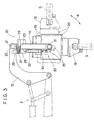
- Fig. 3 is a side view showing the embodiment shown in Fig. 1.
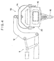
- Fig. 4 is a view showing a conventional vibrating pile driver.
- Fig. 5 is a view illustrating the operation of the positional changes of the conventional example shown in Fig. 4.
- Fig. 1 is a front view showing an embodiment of a vibration generating apparatus according to the present invention.
- Fig. 2 and Fig. 3 are a plan view and a side view showing the apparatus respectively.
- the units corresponding to those of the conventional vibrating pile driver 50 shown in the aforesaid Fig. 4 and Fig. 5 are referenced by the same marks, and any duplicating descriptions thereof are omitted.
- a vibrating pile driver 10 of the present embodiment is provided with a coupling arm unit 12 attachable to the operational arm 5 of a construction machine such as hydraulic shovel, etc., which is structured to allow its position to be shifted as in the conventional driver described earlier, and one end of a suspension shaft 22 is fitted in a supporting shaft 21 mounted at the leading end of this coupling arm 12 so that the suspension shaft can be rotated in the horizontal plane.
- a hanger unit 14 is supported through a bearing unit 23 so that the hanger unit can be rotated in the horizontal plane.
- a first rotation driving mechanism 25 is inclusively mounted between the suspension shaft unit 22 and the hanger unit 14 to couple them.
- the first rotation driving mechanism 25 includes a hydraulic motor 26 fixed to the suspension shaft unit 22, a driving gear 27 fixed to the rotational shaft thereof, a driven gear 29, which is fixed to the bearing unit 23 integrated with the hanger unit 14, to engage with the driving gear 27.
- a main body 20 is supported through a pair of rotational shafts 31 so as to be relatively rotated in the vertical plane.
- the main body 20 comprises a vibrator 15 which generates the exciting power by the supply and exhaust of the activated hydraulic pressure from the hydraulic pressuring unit externally arranged (not shown), and a chuck 16 installed at the lower end of this vibrator 15, which causes a pile S to be vibrated vertically in a state where the pile is being held by the chuck.
- the main body 20 as a whole is structured to rotate integrally with the rotational shaft 31.
- a pair of second rotation driving mechanism 30 are inclusively arranged between the hanger unit 14 and the main body 20 to couple them.
- Each of the second rotation driving mechanisms 30 is structured to include a hydraulic cylinder 32, the trailing end of which is rotatably fixed to the hanger unit 14, and a rocking arm 35, the one end of which is rotatably connected to the leading end of the piston rod 34 of the hydraulic cylinder 32 while the other end thereof is fittedly fixed to the rotational shaft 31 connecting the hanger unit 14 and the main body 20
- the hydraulic motor 26 of the above-mentioned first rotation driving mechanism 25 and the hydraulic cylinder 32 of the second rotation driving mechanism 30 are respectively operated, for example, by the activated hydraulic pressure from the hydraulic pressuring unit common to the vibrator 15, for example.
- the operational control is therefore performed, for example, by a remote control through an operation board provided in the driver's seat, etc., of the hydraulic shovel.
- first rotation driving mechanism 25 and the second rotation driving mechanism 30 are not limited to those set forth above, and as a matter of course, the hydraulic motor 26 can be replaced by an electric motor while a pneumatic cylinder can be employed in place of the hydraulic cylinder 32.
Landscapes
- Engineering & Computer Science (AREA)
- Life Sciences & Earth Sciences (AREA)
- General Life Sciences & Earth Sciences (AREA)
- Mining & Mineral Resources (AREA)
- Paleontology (AREA)
- Civil Engineering (AREA)
- General Engineering & Computer Science (AREA)
- Structural Engineering (AREA)
- Placing Or Removing Of Piles Or Sheet Piles, Or Accessories Thereof (AREA)
Description
- The present invention relates to a vibrating pile driver of a construction machine comprising a coupling arm unit attached to the operational arm of the construction machine (e.g., hydraulic shovel , etc), a rotary hanger unit attached to the coupling arm, and a vibration generating apparatus consisting of a main body and a chuck which is attached to the rotary hanger unit.
- Generally, a vibrating pile driver actuates its vibrator to vibrate a chuck in the direction (usually, vertical direction) of piling while the pile is being held by the chuck to perform its operation in such a manner that the pile is sunk (driven) into the ground with the weight of the pile driver and the pile itself while frictional resistance between the pile and the ground is kept small. Also, as it is possible to keep the frictional resistance between the pile and the ground small by vibration, such operation is utilized for drawing from the ground the pile which has been driven thereinto.
- The type of a vibrating pile driver of this kind is generally such that the driver is suspended from a crane or the like. However, in order to improve the mobility and the handling operativity, the applicant hereof has developed a vibrating
pile driver 50, as shown in Fig. 4 and Fig. 5, which comprises acoupling arm unit 12 attachable to theoperational arm 5 of a construction machine such as a hydraulic shovel, etc., which is structured to allow its position to be shifted; ahanger unit 14 connected to thiscoupling arm unit 12, which is relatively rotatable in the vertical plane and the horizontal plane; amain body 20 having avibrator 15 for generating the exciting power and achuck 16 for holding a pile while being vibrated by thevibrator 15, which is connected to thehanger unit 14 and is relatively rotatable in the vertical plane, compare with the pre-characterising portion of claim 1. - In a vibrating pile driver as shown in Figures 4 and 5 the
coupling arm unit 12,hanger unit 14, andmain body 20 can interrelatedly change the positions thereof to adjust arbitrarily the direction of a pile or the direction of the piling operation, and at the same time, to perform the piling operation rapidly without a problem in a narrow place such as a farm road or an alleyway or in a place where buildings are in the immediate vicinity. Moreover, at the time of installing, removing, or replacing the pile, it is possible to install the pile sideways (in the horizontal direction) or to remove the pile from thechuck 16 after having rotated themain body 20 in the vertical plane to position themain body 20 horizontally against thehanger unit 14. Hence, these operations can be performed with ease and safety. - However, in the above-mentioned vibrating
pile driver 50, the rotation of thehanger unit 14 against thecoupling arm unit 12 in the horizontal plane and the vertical plane are respectively performed by an operator manually. Therefore, there are still problems encountered that these operations are not only troublesome and complicated, but present some aspects which require further consideration in respect of the safety. - According to the present invention there is provided a vibrating pile driver comprising:
a coupling arm unit attachable to the operational arm of a construction machine such as a hydraulic shovel;
a hanger unit coupled with said coupling arm unit and rotatable relative to said coupling arm unit in a vertical plane and also about a vertical axis;
a main body, having a vibrator and a chuck to be vibrated by said vibrator and for holding a pile, coupled with said hanger unit and rotatable about a horizontal axis relative to said hanger unit, characterised by at least one rotation driving mechanism selected from :
a first rotation driving mechanism between the coupling arm unit and the hanger unit to relatively rotate them about the vertical axis; and a second rotation driving mechanism between the hanger unit and the main body to relatively rotate them about the horizontal axis. - In the vibrating pile driver of the present invention the hanger unit may be rotated relative to the coupling arm unit automatically by the first rotation driving mechanism. Also, the main body may be rotated relative to the hanger unit automatically by the second rotation driving mechanism. Hence, the positional changes of the hanger unit and main body can be performed automatically by the remote control rapidly and easily, and further, with safety, so that the mobility and operativity of the pile driving, the pile installation and removal, etc. can be improved.
- The present invention will be more clearly understood from the following description, given by way of example only, with regard to the accompanying drawings in which:
- Fig. 1 is a front view showing an embodiment of a vibration generating apparatus according to the present invention.
- Fig. 2 is a plan view showing the embodiment shown in Fig. 1.
- Fig. 3 is a side view showing the embodiment shown in Fig. 1.
- Fig. 4 is a view showing a conventional vibrating pile driver.
- Fig. 5 is a view illustrating the operation of the positional changes of the conventional example shown in Fig. 4.
-
- 10.
- vibrating pile driver
- 12.
- coupling arm unit
- 14.
- hanger unit
- 15.
- vibration generating apparatus
- 16.
- chuck
- 20.
- main body
- 25.
- the first rotation driving mechanism
- 26.
- hydraulic motor
- 30.
- the second rotation driving mechanism
- 32.
- hydraulic cylinder
- Fig. 1 is a front view showing an embodiment of a vibration generating apparatus according to the present invention. Fig. 2 and Fig. 3 are a plan view and a side view showing the apparatus respectively. In these figures, the units corresponding to those of the conventional vibrating
pile driver 50 shown in the aforesaid Fig. 4 and Fig. 5 are referenced by the same marks, and any duplicating descriptions thereof are omitted. - A vibrating
pile driver 10 of the present embodiment is provided with acoupling arm unit 12 attachable to theoperational arm 5 of a construction machine such as hydraulic shovel, etc., which is structured to allow its position to be shifted as in the conventional driver described earlier, and one end of asuspension shaft 22 is fitted in a supportingshaft 21 mounted at the leading end of thiscoupling arm 12 so that the suspension shaft can be rotated in the horizontal plane. To the other end of thesuspension shaft unit 22, ahanger unit 14 is supported through abearing unit 23 so that the hanger unit can be rotated in the horizontal plane. - Then, a first
rotation driving mechanism 25 is inclusively mounted between thesuspension shaft unit 22 and thehanger unit 14 to couple them. The firstrotation driving mechanism 25 includes ahydraulic motor 26 fixed to thesuspension shaft unit 22, adriving gear 27 fixed to the rotational shaft thereof, a drivengear 29, which is fixed to thebearing unit 23 integrated with thehanger unit 14, to engage with thedriving gear 27. - Also, in the
hanger unit 14, amain body 20 is supported through a pair ofrotational shafts 31 so as to be relatively rotated in the vertical plane. Themain body 20 comprises avibrator 15 which generates the exciting power by the supply and exhaust of the activated hydraulic pressure from the hydraulic pressuring unit externally arranged (not shown), and achuck 16 installed at the lower end of thisvibrator 15, which causes a pile S to be vibrated vertically in a state where the pile is being held by the chuck. Themain body 20 as a whole is structured to rotate integrally with therotational shaft 31. - Subsequently, a pair of second
rotation driving mechanism 30 are inclusively arranged between thehanger unit 14 and themain body 20 to couple them. Each of the secondrotation driving mechanisms 30 is structured to include ahydraulic cylinder 32, the trailing end of which is rotatably fixed to thehanger unit 14, and arocking arm 35, the one end of which is rotatably connected to the leading end of thepiston rod 34 of thehydraulic cylinder 32 while the other end thereof is fittedly fixed to therotational shaft 31 connecting thehanger unit 14 and themain body 20 - The
hydraulic motor 26 of the above-mentioned firstrotation driving mechanism 25 and thehydraulic cylinder 32 of the secondrotation driving mechanism 30 are respectively operated, for example, by the activated hydraulic pressure from the hydraulic pressuring unit common to thevibrator 15, for example. The operational control is therefore performed, for example, by a remote control through an operation board provided in the driver's seat, etc., of the hydraulic shovel. With thehydraulic motor 26 being in motion, thehanger unit 14 is rotated in the horizontal plane integrally with the drivengear 29 as indicated by arrow a in Fig. 2. Then, the positions of thehanger unit 14 and themain body 20 are shifted against thecoupling arm unit 12. On the other hand, when thehydraulic cylinder 32 is actuated, the rockingarm 35 is rotated integrally with therotational shaft 31 as indicated by arrow b in Fig. 3. Thus, the position of themain body 20 is shifted in the vertical plane. - In this way, the positional changes of the
hanger unit 14 and themain body 20 are automatically performed by the remote control rapidly and easily, and further, with safety, thus making it possible to improve the mobility and operativity of the piling, and the pile installation and removal, etc. - In this respect, the structures, etc. of the first
rotation driving mechanism 25 and the secondrotation driving mechanism 30 are not limited to those set forth above, and as a matter of course, thehydraulic motor 26 can be replaced by an electric motor while a pneumatic cylinder can be employed in place of thehydraulic cylinder 32.
Claims (5)
- A vibrating pile driver comprising:
a coupling arm unit (12) attachable to the operational arm (5) of a construction machine such as a hydraulic shovel;
a hanger unit (14) coupled with said coupling arm (12) unit and rotatable relative to said coupling arm unit (12) in a vertical plane and also about a vertical axis;
a main body (20), having a vibrator (15) and a chuck (16) to be vibrated by said vibrator (15) and for holding a pile (5), coupled with said hanger unit (14) and rotatable about a horizontal axis relative to said hanger unit (14), characterised by
at least one rotation driving mechanism selected from:
a first rotation driving mechanism (25) provided between said coupling arm unit (12) and said hanger unit (14) for relatively rotating them about the horizontal axis; and
a second rotation driving mechanism (30) provided between said hanger unit (14) and said main body (20) for relatively rotating them about the horizontal axis. - A vibrating pile driver of claim 1 comprising both said a first and second rotation driving mechanism.
- A vibrating pile driver according to claim 1 or 2 with remote control means for operating the first rotation driving mechanism (25) and/or the second rotation driving mechanism (30).
- A vibrating pile driver of any preceding claim in which the first rotation driving mechanism comprises:-
a motor (26);
a driving gear (27) ; and
a driven gear (29). - A vibrating pile driver of any preceding claim in which the second rotation driving mechanism (30) comprises a piston (32) and a rocking arm (35).
Applications Claiming Priority (2)
| Application Number | Priority Date | Filing Date | Title |
|---|---|---|---|
| JP3007283A JPH04315609A (en) | 1991-01-24 | 1991-01-24 | Vibratory pile driver |
| JP7283/91 | 1991-01-24 |
Publications (2)
| Publication Number | Publication Date |
|---|---|
| EP0496167A1 EP0496167A1 (en) | 1992-07-29 |
| EP0496167B1 true EP0496167B1 (en) | 1993-11-24 |
Family
ID=11661709
Family Applications (1)
| Application Number | Title | Priority Date | Filing Date |
|---|---|---|---|
| EP91311889A Expired - Lifetime EP0496167B1 (en) | 1991-01-24 | 1991-12-20 | Vibrating pile driver |
Country Status (5)
| Country | Link |
|---|---|
| US (1) | US5257667A (en) |
| EP (1) | EP0496167B1 (en) |
| JP (1) | JPH04315609A (en) |
| KR (1) | KR950004684B1 (en) |
| DE (1) | DE69100684T2 (en) |
Cited By (1)
| Publication number | Priority date | Publication date | Assignee | Title |
|---|---|---|---|---|
| EP3329052B1 (en) * | 2015-07-29 | 2022-05-11 | Ozkan, Aydin | A gripping machine |
Families Citing this family (28)
| Publication number | Priority date | Publication date | Assignee | Title |
|---|---|---|---|---|
| FI923880A0 (en) | 1991-09-30 | 1992-08-28 | Raunisto Airi | SLAGANORDNING. |
| DE19732532C2 (en) * | 1997-07-29 | 1999-10-28 | Tracto Technik | Method and device for horizontal directional drilling |
| US5988297A (en) * | 1998-03-24 | 1999-11-23 | Hydraulic Power Systems, Inc. | Variable eccentric vibratory hammer |
| US6353006B1 (en) | 1999-01-14 | 2002-03-05 | Bayer Corporation | Substituted 2-arylimino heterocycles and compositions containing them, for use as progesterone receptor binding agents |
| GB2351111B (en) * | 1999-06-14 | 2002-01-23 | Expotech Ltd | A device for driving piles |
| US6386295B1 (en) | 2000-03-10 | 2002-05-14 | Paul W. Suver | Vibratory driver for pipe piling |
| JP2002302947A (en) * | 2001-04-09 | 2002-10-18 | Hitachi Constr Mach Co Ltd | Pile driving and pulling device |
| KR100487111B1 (en) * | 2001-05-09 | 2005-05-04 | 주식회사 수산 서비스 | Pile Driver |
| US7591612B2 (en) | 2003-07-24 | 2009-09-22 | Yk Equipment Pte Ltd. | Piling device |
| JP4543407B2 (en) * | 2003-12-01 | 2010-09-15 | 調和工業株式会社 | Vibration pile punching machine |
| US7407343B2 (en) * | 2004-12-28 | 2008-08-05 | Van Halteren Peter | Hydraulic-forced resonance-free vibratory sheet piling driving and extraction machine |
| US20080310923A1 (en) * | 2007-06-14 | 2008-12-18 | Innovative Pile Driving Products, Llc | Modular vibratory pile driver system |
| SE530501C2 (en) * | 2007-09-12 | 2008-06-24 | Bruno Vedin | Lifting and lowering device for e.g. pile, has outer casing held against inner casing by vibration damping device and provided with surfaces for centering and vertically positioning pile |
| KR100851430B1 (en) | 2008-02-14 | 2008-08-11 | 박정열 | Articulated Vibro Hammer Device |
| US8974771B2 (en) * | 2010-03-09 | 2015-03-10 | Penn-Century, Inc. | Apparatus and method for aerosol delivery to the lungs or other locations of the body |
| PL2561143T3 (en) * | 2010-04-19 | 2018-02-28 | Movax Oy | A device meant for forcing piles into the ground |
| US20140294513A1 (en) * | 2011-07-25 | 2014-10-02 | Krinner Innovation Gmbh | Device for Inserting Foundation Piles |
| FR2982888B1 (en) * | 2011-11-22 | 2013-11-29 | P T C | SWIVEL CLAMP FOR VIBRATOR AND VIBRATOR HAVING SUCH A CLAMP |
| DE102011120773B4 (en) * | 2011-12-09 | 2022-03-03 | Thyssenkrupp Infrastructure Gmbh | Device, device and method, in particular for the foundation of offshore structures |
| FI124083B (en) * | 2012-01-27 | 2014-03-14 | Movax Oy | Impact device intended for piling piles into the soil |
| CN103243716A (en) * | 2013-04-12 | 2013-08-14 | 东莞市海德机械有限公司 | A High-frequency Vibration Hammer for Clamping Pile with Automatic Flipping of the Chuck |
| EP3256648B1 (en) | 2015-02-10 | 2019-10-30 | Ozkan, Aydin | A connection adapter |
| CN105464116B (en) * | 2016-01-16 | 2018-08-21 | 东莞市新宝钢结构工程有限公司 | High-speed hydraulic pile driving and drawing machine |
| GB201604833D0 (en) * | 2016-03-22 | 2016-05-04 | Vp Plc And Dale Mansfield Ltd | Improvements in and relating to tools |
| RU179001U1 (en) * | 2017-02-22 | 2018-04-24 | Александр Иванович Егоров | DRILLING EQUIPMENT |
| PH12022552767A1 (en) * | 2020-04-24 | 2024-03-25 | Dae Ryuk Kwon | Vibratory pile driver in which damage by vibratory pile driving is reduced |
| EP4098803B1 (en) * | 2021-05-31 | 2024-08-07 | ABI Anlagentechnik-Baumaschinen-Industriebedarf Maschinenfabrik und Vertriebsgesellschaft mbH | Vibrodisplacement lance and method for equipping a leader with a vibrodisplacement lance |
| US12258724B2 (en) * | 2021-07-05 | 2025-03-25 | Giken Ltd. | Pile press-in construction method, pile supplying device, and pile press-in device |
Family Cites Families (8)
| Publication number | Priority date | Publication date | Assignee | Title |
|---|---|---|---|---|
| US3033394A (en) * | 1959-06-29 | 1962-05-08 | Kash Products Inc | Multipurpose apparatus for earthworking and the like |
| DE1634275A1 (en) * | 1966-11-18 | 1970-03-26 | Bodine Jun Albert George | Method and device for driving tie rods and the like. |
| US3909149A (en) * | 1971-11-01 | 1975-09-30 | Allied Steel Tractor Prod Inc | Hydraulic vibratory compactor |
| JPS5612429A (en) * | 1979-07-06 | 1981-02-06 | Kubota Ltd | Driving method of pile |
| JPS5789022A (en) * | 1980-11-25 | 1982-06-03 | Kensetsu Kikai Chiyousa Kk | Vibrating pile driver |
| JPS5848690B2 (en) * | 1982-03-15 | 1983-10-29 | 淳三 溝「淵」 | Vibratory pile driving and pile extraction machine |
| JPS57184129A (en) * | 1982-03-31 | 1982-11-12 | Junzo Mizobuchi | Vibration type pile-driving and drawing machine |
| JPS6351521A (en) * | 1986-08-20 | 1988-03-04 | Chiyouwa Kogyo Kk | Vibration-type pile driver |
-
1991
- 1991-01-24 JP JP3007283A patent/JPH04315609A/en active Pending
- 1991-11-08 US US07/790,617 patent/US5257667A/en not_active Expired - Fee Related
- 1991-12-09 KR KR1019910022491A patent/KR950004684B1/en not_active Expired - Fee Related
- 1991-12-20 DE DE69100684T patent/DE69100684T2/en not_active Expired - Fee Related
- 1991-12-20 EP EP91311889A patent/EP0496167B1/en not_active Expired - Lifetime
Cited By (1)
| Publication number | Priority date | Publication date | Assignee | Title |
|---|---|---|---|---|
| EP3329052B1 (en) * | 2015-07-29 | 2022-05-11 | Ozkan, Aydin | A gripping machine |
Also Published As
| Publication number | Publication date |
|---|---|
| EP0496167A1 (en) | 1992-07-29 |
| JPH04315609A (en) | 1992-11-06 |
| US5257667A (en) | 1993-11-02 |
| KR920014996A (en) | 1992-08-26 |
| DE69100684T2 (en) | 1994-06-09 |
| DE69100684D1 (en) | 1994-01-05 |
| KR950004684B1 (en) | 1995-05-04 |
Similar Documents
| Publication | Publication Date | Title |
|---|---|---|
| EP0496167A1 (en) | Vibrating pile driver | |
| CN100420818C (en) | Portable vibratory screed with vibration restraint | |
| US6305445B1 (en) | Stump grinding machine having improved cutting boom support structure | |
| EP0475965B1 (en) | A device for a sorting shovel | |
| JPH11131472A (en) | Inner excavation device for rotatably pressing-in hollow pile | |
| JP2866341B2 (en) | Vertical groove milling cutter | |
| JPH08226237A (en) | Crashing device | |
| US20080264658A1 (en) | Apparatus for removing obstructions from a worksite | |
| JPH0739969Y2 (en) | Work implement mounting device | |
| JP2580471B2 (en) | Pile driver for arm type working machine | |
| JP4352382B2 (en) | Tunnel wall cutting equipment | |
| JP2017203304A (en) | Scattering / dust suction system | |
| JPH01165832A (en) | Backhoe and usage thereof | |
| JP2524726B2 (en) | Small diameter pipe propulsion machine | |
| JPH08209735A (en) | Vibration roller device of construction machinery | |
| AU762584B2 (en) | Cutting tool module | |
| JP3679339B2 (en) | Swing angle detector | |
| JP3337532B2 (en) | Work equipment mounting device | |
| JPH0472921B2 (en) | ||
| JPH1136367A (en) | Hydraulic cylinder provided with rotary encoder | |
| JPH07224595A (en) | Cutter bit exchanging device for shield machine | |
| JPH09242014A (en) | Compaction machine with steering function | |
| JPH08290342A (en) | Machine tool | |
| KR970006206Y1 (en) | Vibrating pile driver | |
| JP2582833Y2 (en) | Mounting structure of offset sensor |
Legal Events
| Date | Code | Title | Description |
|---|---|---|---|
| PUAI | Public reference made under article 153(3) epc to a published international application that has entered the european phase |
Free format text: ORIGINAL CODE: 0009012 |
|
| AK | Designated contracting states |
Kind code of ref document: A1 Designated state(s): CH DE FR GB IT LI NL |
|
| 17P | Request for examination filed |
Effective date: 19921022 |
|
| 17Q | First examination report despatched |
Effective date: 19930121 |
|
| GRAA | (expected) grant |
Free format text: ORIGINAL CODE: 0009210 |
|
| AK | Designated contracting states |
Kind code of ref document: B1 Designated state(s): CH DE FR GB IT LI NL |
|
| ITF | It: translation for a ep patent filed | ||
| REF | Corresponds to: |
Ref document number: 69100684 Country of ref document: DE Date of ref document: 19940105 |
|
| ET | Fr: translation filed | ||
| PLBE | No opposition filed within time limit |
Free format text: ORIGINAL CODE: 0009261 |
|
| STAA | Information on the status of an ep patent application or granted ep patent |
Free format text: STATUS: NO OPPOSITION FILED WITHIN TIME LIMIT |
|
| 26N | No opposition filed | ||
| PGFP | Annual fee paid to national office [announced via postgrant information from national office to epo] |
Ref country code: FR Payment date: 19961021 Year of fee payment: 6 |
|
| PGFP | Annual fee paid to national office [announced via postgrant information from national office to epo] |
Ref country code: CH Payment date: 19961111 Year of fee payment: 6 |
|
| PGFP | Annual fee paid to national office [announced via postgrant information from national office to epo] |
Ref country code: GB Payment date: 19961211 Year of fee payment: 6 |
|
| PGFP | Annual fee paid to national office [announced via postgrant information from national office to epo] |
Ref country code: NL Payment date: 19961231 Year of fee payment: 6 |
|
| PGFP | Annual fee paid to national office [announced via postgrant information from national office to epo] |
Ref country code: DE Payment date: 19970227 Year of fee payment: 6 |
|
| PG25 | Lapsed in a contracting state [announced via postgrant information from national office to epo] |
Ref country code: GB Free format text: LAPSE BECAUSE OF NON-PAYMENT OF DUE FEES Effective date: 19971220 |
|
| PG25 | Lapsed in a contracting state [announced via postgrant information from national office to epo] |
Ref country code: LI Free format text: LAPSE BECAUSE OF NON-PAYMENT OF DUE FEES Effective date: 19971231 Ref country code: FR Free format text: THE PATENT HAS BEEN ANNULLED BY A DECISION OF A NATIONAL AUTHORITY Effective date: 19971231 Ref country code: CH Free format text: LAPSE BECAUSE OF NON-PAYMENT OF DUE FEES Effective date: 19971231 |
|
| PG25 | Lapsed in a contracting state [announced via postgrant information from national office to epo] |
Ref country code: NL Free format text: LAPSE BECAUSE OF NON-PAYMENT OF DUE FEES Effective date: 19980701 |
|
| GBPC | Gb: european patent ceased through non-payment of renewal fee |
Effective date: 19971220 |
|
| REG | Reference to a national code |
Ref country code: CH Ref legal event code: PL |
|
| NLV4 | Nl: lapsed or anulled due to non-payment of the annual fee |
Effective date: 19980701 |
|
| PG25 | Lapsed in a contracting state [announced via postgrant information from national office to epo] |
Ref country code: DE Free format text: LAPSE BECAUSE OF NON-PAYMENT OF DUE FEES Effective date: 19980901 |
|
| REG | Reference to a national code |
Ref country code: FR Ref legal event code: ST |
|
| PG25 | Lapsed in a contracting state [announced via postgrant information from national office to epo] |
Ref country code: IT Free format text: LAPSE BECAUSE OF NON-PAYMENT OF DUE FEES Effective date: 20051220 |