EP0495647A1 - Dynamic laser marking - Google Patents
Dynamic laser marking Download PDFInfo
- Publication number
- EP0495647A1 EP0495647A1 EP92300350A EP92300350A EP0495647A1 EP 0495647 A1 EP0495647 A1 EP 0495647A1 EP 92300350 A EP92300350 A EP 92300350A EP 92300350 A EP92300350 A EP 92300350A EP 0495647 A1 EP0495647 A1 EP 0495647A1
- Authority
- EP
- European Patent Office
- Prior art keywords
- accordance
- moving body
- moving
- spot
- high energy
- Prior art date
- Legal status (The legal status is an assumption and is not a legal conclusion. Google has not performed a legal analysis and makes no representation as to the accuracy of the status listed.)
- Granted
Links
Images


Classifications
-
- B—PERFORMING OPERATIONS; TRANSPORTING
- B41—PRINTING; LINING MACHINES; TYPEWRITERS; STAMPS
- B41M—PRINTING, DUPLICATING, MARKING, OR COPYING PROCESSES; COLOUR PRINTING
- B41M5/00—Duplicating or marking methods; Sheet materials for use therein
- B41M5/26—Thermography ; Marking by high energetic means, e.g. laser otherwise than by burning, and characterised by the material used
- B41M5/262—Thermography ; Marking by high energetic means, e.g. laser otherwise than by burning, and characterised by the material used recording or marking of inorganic surfaces or materials, e.g. glass, metal, or ceramics
-
- B—PERFORMING OPERATIONS; TRANSPORTING
- B23—MACHINE TOOLS; METAL-WORKING NOT OTHERWISE PROVIDED FOR
- B23K—SOLDERING OR UNSOLDERING; WELDING; CLADDING OR PLATING BY SOLDERING OR WELDING; CUTTING BY APPLYING HEAT LOCALLY, e.g. FLAME CUTTING; WORKING BY LASER BEAM
- B23K26/00—Working by laser beam, e.g. welding, cutting or boring
- B23K26/08—Devices involving relative movement between laser beam and workpiece
- B23K26/083—Devices involving movement of the workpiece in at least one axial direction
- B23K26/0838—Devices involving movement of the workpiece in at least one axial direction by using an endless conveyor belt
-
- B—PERFORMING OPERATIONS; TRANSPORTING
- B23—MACHINE TOOLS; METAL-WORKING NOT OTHERWISE PROVIDED FOR
- B23K—SOLDERING OR UNSOLDERING; WELDING; CLADDING OR PLATING BY SOLDERING OR WELDING; CUTTING BY APPLYING HEAT LOCALLY, e.g. FLAME CUTTING; WORKING BY LASER BEAM
- B23K2101/00—Articles made by soldering, welding or cutting
- B23K2101/007—Marks, e.g. trade marks
-
- B—PERFORMING OPERATIONS; TRANSPORTING
- B41—PRINTING; LINING MACHINES; TYPEWRITERS; STAMPS
- B41M—PRINTING, DUPLICATING, MARKING, OR COPYING PROCESSES; COLOUR PRINTING
- B41M5/00—Duplicating or marking methods; Sheet materials for use therein
- B41M5/26—Thermography ; Marking by high energetic means, e.g. laser otherwise than by burning, and characterised by the material used
Definitions
- the present invention relates to a method and apparatus for marking a moving body of material using a high energy density beam.
- the ink jet marker which is capable of directing a controlled jet of ink on to a moving package so as to produce a desired indicum.
- Such devices are capable of marking up to 1000 items a minute but require constant attention and frequent overhaul to prevent the nozzle of the ink jet from fouling. Such an overhaul may necessitate the shutting down of the production line with a consequent loss in manufacturing or processing time.
- devices of this type consume a large quanitity of materials such as ink and solvent resulting in them having a significant running cost. Questions have also been raised as to the indelibility of the resulting mark.
- Laser marking offers a clean and elegent alternative to ink jet marking and provides the body concerned with a truely indelible mark.
- a beam of unfocused laser radiation is passed through a mask so as to produce the desired pattern while in the second a beam of laser radiation is scanned across the object concerned tracing out the desired pattern.
- US Patent No. 4,758,703 provides an example of a marking technique falling into the first category and it describes a method of covertly encoding a microscopically visible pattern onto the surface of a moving object.
- the presence of a moving object is sensed and the speed of its approach measured so that at the appropriate moment, when the object passes the laser head, a beam of unfocused laser radiation is directed onto the object through a mask.
- It is the mask that is responsible for generating the pattern of the marking and comprises a mask plate having a cross-sectional area greater than that of the beam and incorporates a matrix of holes which may or may not be obscured.
- the beam is focused to reduce the size of the pattern produced on the surface of the package as well as to increase the intensity of the beam.
- the intensity of the beam is carefully controlled so that the final pattern is barely etched on to the surface and remains invisible to the naked eye.
- The, Applicant's own co-pending UK Patent Application No. 9117521.6 provides an example of a scanning method of laser marking and relates to a method and apparatus for providing a body of material with a sub-surface mark in the form of an area of increased opacity to electromagnetic radiation.
- the method comprises the steps of directing at a surface of the body a high energy density beam to which the material is transparent and bringing the beam to a focus at a location spaced from the surface and within the body so as to cause the localised ionisation of the material.
- UK Patent Application No. 9117521.6 additionally relates to a body marked in accordance with the said method or by use of the said apparatus.
- the scanning laser marking technique has the advantage of being more flexible in that the shape of the desired mark may be changed externally without interrupting the operation of the laser to change a mask element
- the technique has yet to be used commercially for marking moving bodies because of fears that the resulting mark would be blurred or else "Stretched" in the direction of motion of the body. This fear has to date confined the scanning laser marking technique to applications in which the body to be marked is stationary leaving moving bodies to be marked using the masked beam technique although the clarity of the resulting mark using this technique is also ultimately limited by the speed of movement of the moving body.
- a method of marking a moving body of material comprising the steps of directing at the moving body a high energy density beam, concentrating the beam so as to produce an illuminated spot at a location on or within the moving body, and moving said spot in accordance with the resultant of two components of movement, the first being equal to the velocity of the moving body and the second being relative to the moving body so as to create a mark of a predetermined shape.
- the additional step of determining the velocity of the moving body Whilst it is recognised that the velocity of the moving body may be determined by monitoring the speed of movement of the means used to transport the body, the velocity of the moving body is preferably determined by means of direct measurement.
- the high energy density beam is directed at the moving body by causing the path of the moving body to intersect the path of the actuated high energy density beam and acutating the high energy density beam at a predetermined time after the moving body passes a position a known distance from the point of intersection, that time being dependant upon the velocity of the moving body.
- the high energy density beam is preferably brought to a focus at a location within the moving body so as to cause localised ionisation of the material and the creation of a mark in the form of an area of increased opacity to electromagentic radiation.
- the moving body of material may be transparent to electrmomagnetic radiation at wavelengths within the visible region thereby rendering the mark visible to the naked eye.
- the material may be of glass or plastics.
- the moving body of material may be opaque to electromagnetic radiation at wavelengths within the visible region so that the mark may only be "seen” by optical instruments operating at an appropriate wavelength within the electromganetic spectrum. While such a mark is not capable of performing many of the functions of its visible counterpart it does represent a truly indelible covert mark.
- the mark may comprise one or more numerals, letters or symbols or a combination thereof which in turn may represent an indentification, a trade mark, a machine readable code or any other desired indicum.
- the mark may be three dimensional.
- an apparatus for marking a moving body of material comprising means for creating a high energy density beam and directing the beam at the moving body, means for concentrating the beam so as to produce an illuminated spot at a location on or within the moving body and means for moving said spot in accordance with the resultant of two components of movement, the first being equal to the velocity of the moving body and the second being relative to the moving body so as to create a mark of a predetermined shape.
- the means for moving the spot in accordance with the resultant of two components includes means for moving said spot in accordance with the said second of the two components, the means perferably including at least one moveable mirror disposed in the path of the beam.
- the movement of the mirror may be controlled in accordance with a computer program enabling the final shape of the mark to be easily manipulated while the moveable mirror itself may comprise a galvanomoeter mirror.
- any suitable means may be provided to move the mirror such as a servo motor or manual joy stick, the properties of a galvanometer mirror provide a speed of response and an ease of control that represent a significant advantage over alternative control means.
- the means for moving the spot in accordance with the said second of the two components is also capable of moving the spot in accordance with the said first of the two components.
- the means for moving said spot in accordanmce with the resultant of two components includes additional means for moving the spot in accordance with the said first of the two components, the means preferably including at least one rotatably mounted mirror whose speed of rotation is varied in accordance with the velocity of the moving body.
- the rotatably mounted mirror of the preceding embodiment is multi-faceted.
- the means for moving the spot in accordance with the said first of the two components includes at least one mirror moveable at the same velocity as the moving body.
- the means for moving the spot in accordance with the said first of the two components includes at least one acusto-optic or elctro-optic crystal.
- the velocity of the moving body may be determined by monitoring the speed of movement of the means used to transport the body, the velocity of the moving body is preferably determined by means of direct measurement. For example, in a particular arrangement, the velocity of the moving body may be determined by measuring the time taken for the moving body to travel between two opto-detectors spaced a known distance apart.
- the high energy density beam is directed at the moving bony by causing the path of the moving body to intersect the path of the high energy beam when actuated and providing means to actuate the high energy density beam at a predetermined time after the moving body passes a position a known distance from the point of intersection, that time being dependant upon the velocity of the moving body.
- the means for concentrating the beam may include a lens element having a focal length that varies across its width so as to compensate for a particular de-focusing effect.
- the means for concentrating the beam may include a zoom lens to either again compensate for a particular de-focusing effect or to enable marks to be made at different depths within the body and so allow for the creation of three dimensional marks.
- the means for concentrating the beam may include a diverging lens.
- the means for creating a high energy density beam preferably comprises a CO2 laser.
- the means for creating a high energy density beam preferably comprises a laser which is focused so as to have a peak energy density at the focus of a least 10 J/cm2.
- This peak energy density is preferably achieved by means of a laser which is focused to have a power density at the focus of at least 107 W/cm2 and is pulsed with a pulse duration of at least 10 ⁇ 6 seconds.
- the body of material to be marked is transparent to electromagnetic radiation at wavelengths within the visible region, then the means for creating the required high energy density beam is preferably a Nd-YAG (Neodymium-doped Yittrium Aluminium Garnet) laser operating at a wavelength of 1.06 ⁇ m.
- Nd-YAG Neodymium-doped Yittrium Aluminium Garnet
- a secondary source of visible laser radiation may be provided to facilitate alignment of the high energy density beam.
- a conveyor belt is preferably provided to transport the moving body and in such circumstances the conveyor belt may be provided with means to control the lateral position of the moving body relative thereto.
- the laser marking station shown in Figure 1 comprises a marking apparatus 10 and a sensing module 12 both of which are contained within a protective housing 14 that straddles a continuously moving conveyor belt 16.
- the conveyor belt 16 is generally of sufficient width to transport to the laser marking station a body of material to be marked and is further defined by a moving web 18 and two vertically projecting side rails 20 and 22.
- the first of the two side rails 20 is fixed relative to the moving web 18 while the other side rail 22 is moveable relative thereto by means of an adjusting screw 24.
- the adjusting screw 24 Upon tightening the adjusting screw 24 the distance between the two side rails 20 and 22 is decreased thereby narowing the effective width of the conveyor belt 16.
- the body of material to be marked which in the accompanying drawings is depicted as a glass bottle 26, is transported to the laser marking station by the conveyor belt 16 and enters the protective housing 14 by a first opening 28. Thereafter the body 26 is transported past the sensing module 12 and the marking appratus 10 before passing out of the protective housing 14 through a second opening 30.
- the distance between the marking apparatus 10 and either of the first or second openings 28 or 30 is such as to ensure that an operator can not accidentally reach inside the protective housing 14 and place his or her hand in front of the marking apparatus 10.
- the sensing module 12 is shown in greater detail in Figure 2 and comprises a pair of opto-detectors 32 and 34 disposed side by side adjacent the conveyor belt 16.
- Each of the opto-detectors 32 and 34 includes a light source 36 and a suitable detector 38 and is aligned with one of a pair of respective retro-reflectors 40 or 42 disposed on the opposite side of the conveyor belt 16.
- Light is emitted from the light source 36 toward the associated retro-reflector whereupon it is reflected back toward the opto-detector and detected by the detector 38.
- the quantity of light detected by the detector 38 is a maximum.
- the light source 36 is selected so as to emit light in the visible or near infra-red region of the elctromagnetic spectrum whilst the detector 38 is chosen not only to be selectively sensitive to this particular frequency range but also to be responsive only to light having the polarisation characteristics of the source 36. In this way the detector 38 is insensitive to light emanating from sources other than the light source 36 or to light reflected from surfaces other than the associated retro-reflector such as, for example, from the surface of the body to be marked since such reflections would typically possess different polarisation characteristics.
- the marking apparatus 10 is shown in greater detail in Figure 3 and comprises of source 44 of laser radiation 46 which is directed so as to interest the path of the moving body 26.
- the marking appartus 10 is designed so as to facilitate the surface marking of the moving body 26.
- laser radiation of a sufficient energy density is directed toward the body 26 causing areas of the surface impinged thereby to melt and reflow leaving a resulting mark.
- the source 44 comprises an RF excited simulated continuous-wave carbon dioxide (CO2) laser that emits a beam of laser radiation 46 having a wavelength of 10.6 ⁇ m and which is consequently invisible to the naked eye. Having been emitted from the CO2 laser 44, the beam of laser radiation 46 is incident upon a first reflecting surface 48 that directs the beam 46 through a beam expander 50 and a beam combiner 52 to a second reflecting surface 54.
- CO2 simulated continuous-wave carbon dioxide
- a second source of laser radiation in the form of a low power He-Ne (Helium-Neon) laser 56, is disposed adjacent to the CO2 laser 44 and emits a secondary beam of visible laser radiation 58 with a wavelength of 638nm.
- the secondary beam 58 impinges upon the beam combiner 52 where it is reflected toward the second reflecting surface 54 coincident with the beam of laser radiation 46 from the CO2 laser 44.
- the necessary properties of the beam combiner 52 are that it should transmit electromagnetic radiation with a wavelength of 10.6 ⁇ m whilst reflecting electromagnetic radiation with a wavelength of 638nm.
- the He-Ne laser beam 58 provides the combined CO2/He-Ne beam 46, 58 with a visible component that facilitates optical alignment.
- the two coincident beams 46, 58 are reflected at the second reflecting surface 54 toward a third reflecting surface 60 and from the third reflecting surface 60 are further reflected toward a fourth reflecting surface 62.
- the combined beam 46, 58 is reflected yet again toward a head unit 64 from whence the combined beam 46, 58 is finally directed so as to intersect the path of the moving body 26.
- the third and fourth reflecting surfaces 60 and 62 are integrally mounted, together with the head unit 64, so as to be adjustable in a vertical plane under the action of a stepping motor 66 (not shown ).
- the combined CO2/He-Ne beam 46, 58 is sequentially incident upon two moveable mirrors 68 and 70.
- the first of the two mirrors 68 is disposed so as to be inclined to combined beam 46, 58 that is incident upon it as a result of reflection from the fourth reflecting surface 62 and is moveable in such a way to cause the beam reflected therefrom to move in a vertical plane.
- the second of the two mirrors 70 is similarly inclined, this time to the beam 46, 58 that is incident upon it as a result of reflection from the first mirror 68 and is moveable in such a way as to cause a reflected beam 46, 58 to move in a horizontal plane.
- the beam 46, 58 emerging from the head unit 64 maybe moved in any desired direction by the simultaneous movement of the first and second mirrors 68 and 70.
- the two moveable mirrors 68 and 70 are mounted on respective first and second galvanometers 72 and 74.
- any suitable means maybe provided to control the movement of the two mirrors 68 and 70, such as by the use of individual servo motors or a manual joystick, the approach adopted combines a speed of response with an ease of control that represents a significant advantage over alternative control means.
- the combined beam 46, 58 is focused by passing through a lens assembly 76 which may include one or more lens elements.
- a first lens element 78 is capable of bringing the beam 46, 58 to a focus at a chosen location on the surface of the body to be marked.
- the maximum power density of the beam 46, 58 is inversely proportional to the square of the radius of the beam 46, 58 at its focus which in turn is inversely proportional to the radius of the beam 46, 58 that is incident upon the focusing lens 78.
- the lens element 78 is typically a short focal length lens having a focal length in the range between 70mm and 80mm so that typical power densities is at the focus of the beam 46, 58 are in excess of 300 W/cm2.
- the mark maybe made to a predetermined shape and in particular, maybe made to comprise one or more numerals, letters or symbols or a combination thereof which in turn may represent an identification, a trade mark, a machine readable code or any other desired indicum.
- the power density required to stimulate thermal interactions at the surface of the body will, of course, depend upon the material of the body and the speed at which the beam 46,58 is scanned. Materials such as perspex may be marked using a beam 46,58 having a power density of as little as approximately 50W/cm2 while to mark some metals it is necessary for the beam 46,58 to have a power density of approximately 1MW/cm2. Bodies made of glass fall between these two extremes and may be marked using a beam 46,58 having a power density of in excess of 300W/cm2 and a scanning speed of 3m/sec.
- the two lasers 44 and 56 and their respective beams 46 and 58 are enclosed within a safety chamber 80 as shown in Figure 4 with the combined beam 46, 58 emerging from the safety chamber 80 only after passing through the lense assembly 76.
- Access to the two lasers 44 and 56 and the various optical elements disposed in the path of the respective beams 46, 58 is gained by means of a door panel 82 which is fitted with an interlock 84 that prevents the operation of the CO2 laser 44 while the door panel 82 is open.
- the He-Ne laser 56 need not necessarily be fitted with an interlock in the same way since it only operates at a very low power and does not represent a significant danger to a skilled operator.
- a single phase electrical mains supply of 240V is fed via the door panel interlock 84 to a mains distribution unit 86 that is disposed below, and isolated from, the safety chamber 80 in order to prevent any electrical effects interfering with the operation of the lasers 44 and 56.
- mains electrical power is provided to the CO2 laser 44 and He-Ne laser 56 as well as to a chiller unit 88 that serves to cool the CO2 laser 44.
- mains electrical power is also supplied to the stepping motor 66 and to a computer 90.
- Three AC/DC convertors and associated voltage regulators provide regulated DC voltage supplies of 9v, 12v and 15v that are fed respectively to the He-Ne laser 56 to facilitate the pumping mechanism, to a further interlock 92 that prevents premature firing of the CO2 laser 44, and to the head unit 64 and in particular to the first and second galvanometers 72 and 74 to produce a predetermined movement of the first and second mirrors 68 and 70.
- the combined operational sequence of the marking appratus 10 and the sensing module 12 is shown schematically in Figure 5 and commences with the computer 90 either calculating or performing a look-up to identify the next mark to be applied.
- the computer 90 may calculate the next mark by adding the necessary increment to the reference number that constitued the previous mark.
- the computer 90 may identify the next mark from one of a pre-programmed list of marks contained in a suitable memory device. However the next mark is identified, it may be displayed on an operator's console along with other information such as the number of bodies marked in a particular batch, the average line speed of the bodies transported past the sensing module 12 and any other desired information.
- the computer 90 calculates the vectors necessary to trace out the mark assuming the body 26 to be stationary at the time of marking. These vectors are transformed into an electrical signal that if used to modulate the 15v DC supply applied to the first and second galvanometers 72 and 74 would produce a series of movements of the first and second mirrors 68 and 70 capable of moving the focus of an actuated laser beam in such a way as to trace out the desired mark.
- adjusting screw 24 is used to narrow the effective width of the conveyor belt 16 adjacent the first opening 28 in the protective housing 14. In this way the effective width of the conveyor belt 16 is made not much wider than the moving body 26 itself thereby providing a degree of control over the lateral distance between the body to be marked and the various components of the sensing module 12 and the marking apparatus 10.
- the sensing module 12 is used to detect the approach of the body to be marked.
- the body 26 reaches opto-detector 32 its leading-edge obstructs the optical path between the light source 36, the retro-reflector 40 and the detector 38 causing the quantity of light detected to fall below a preset threshold value.
- an approriate signal is generated and sent to the computer 90 whereupon a clock is actuated. This clock is not stopped until a time t1 later when the leading-edge of the moving body 26 is detected in the same way at the second opto-detector 34.
- the velocity v of the body to be marked maybe readily calculated by dividing the known distance d1 by the time t1 measured by the clock.
- v d1 t1
- the distance d1 between the two opto-detectors 32 and 34 is preferably made as small as possible.
- opto-detector 34 is caused to abutt opto-detector enabling d1 to be reduced to a value of 1mm.
- the oscillator that forms the basis of the clock is capable of in excess of 5 clock cycles during a typical time interval t1 so that the reduction in d1 does not have a discernable effect on the accuracy to which the velocity v maybe measured.
- the distance d2 maybe decreased to a minimum ultimately limited by the computing power of the computer 90 but which is typically of the order of 5mm.
- the computer 90 calculates the estimated time of arrival t2 of the body to be marked adjacent the marking apparatus 10.
- This time interval however represents the time at which the leading-edge of the body 26 is adjacent the marking apparatus 10 and so, unless the desired mark is to be applied at the leading-edge, a further delay ⁇ t is added to the time interval t 2 to yield a time t3 at which that portion of the body 26 to be marked is adjacent the marking apparatus 10.
- the CO2 laser 44 is actuated and the combined CO2/He-Ne beam 46, 58 focused at the estimated position of the surface of the body 26.
- an electrical signal is generated to modulate the 15v DC supply applied to the first and second galvanometers 72 and 74 that not only reproduces the vectors necessary to trace out the desired mark but also includes a superimposed component that compensates for the movement of the body 26 at the velocity v.
- the modulated 15v DC supply produces a series of movements of the first and second mirrors 68 and 70 that direct the focus of the combined CO2/He-Ne beam 46, 58 so as to trace out the desired mark whilst at the same time moving the mark as it is being traced with a velocity v thereby enabling real time dynamic scanning to take place.
- the body 26 After the body 26 has been marked it continues to be transported by the conveyor belt 16 and passes out the protective housing 14 and away from the laser marking station by way of the second opening 30.
- the marked body 26 may thereafter be transported to further processing stations if required whilst the computer 90 calculates the next mark to be applied and the operational sequence begins all over again.
- the first lens element 78 is of a fixed focal length, each of the above factors will contribute to parts of the mark applied to the body being more or less out of focus. However, with the careful selection of the focal length of the lens element 78 this problem maybe reduced to a minimum.
- the focal length of the first lens element 78 is typically between 70mm and 80mm and is capable of focusing the combined CO2/He-Ne beam 46, 58 so as to yield at the focus a power density that is typically in excess of 300 W/cm2. Having said that however, for a lens element having a focal length within this range, the power density at a small distance ⁇ x from the focus is still sufficient to cause thermal interactions to occur within the body to be marked.
- the lens element 78 has a focal length of 75mm enabling ⁇ x for glass to be as large as 5mm, although the size of ⁇ x is, of course, dependant upon the material of which the body 26 is comprised. Using such a lens however, the apparatus described may efficiently mark moving bodies whose surfaces lie within a small range of distances either side of an optimum distance from the lens assembly 76.
- a second lens element 92 maybe placed in series with the first lens element 78 in order to compensate for one or more of the de-focusing effects described above.
- a lens element 92 may posess a focal length that varies across its width and may, for example, comprise a flat field lens so as to compensate for any curvature of the surface of the body to be marked.
- the lens assembly 76 may include a third lens element 94 in the form of a zoom lens whose focal length may be altered as the body to be marked passes the marking apparatus 10 thereby maintaining the focus of the combined CO2/He-Ne Beam 46, 58 at the desired point on the surface of the body 26 inspite of the de-focusing effects described above.
- a fourth lens element 95 (not shown) taking the form of a diverging lens.
- the fourth lens element 95 of focal length f2 is preferably disposed a distance f2 in front of the focus that would otherwise be produced by the first lens element 78.
- the fourth lens element 95 produces a narrow parallel beam of high energy density radiation which may be directed at the moving body 26 to produce an illuminated spot on the surface thereof.
- the narrow beam has a sufficient power density it may be used to facilitate the surface marking of the moving body 26 whilst at the same time not being prone to any of the de-focusing effects described above.
- the marking apparatus 10 is again designed to facilitate the surface marking of a moving body of material 26 except that rather than superimposing a component that compensates for that movement on the already complex movement of the first and second mirrors 68 and 70, the movement of the body 26 is entirely compensated for by a fifth reflecting surface 96.
- the fifth reflecting surface 96 is rotatably mounted about an axis 98 and is positioned so as to direct on to the moving body 26 the combined CO2/He-Ne beam 46, 58 that is incident upon it as a result of a reflection from the second mirror 70. As the body to be marked passes the marking apparatus 10, the fifth reflecting surface 96 rotates about the axis 98 in such a way as to keep the combined CO2/He-Ne beam 46, 58 directed upon the moving body 26.
- the fifth reflecting surface 96 preferably comprises the mirror of a third galavanometer 100 (not shown). In this way the movement of the fifth reflecting surface 96 may be facilitated with the same speed of response and ease of control as enjoyed by the first and second mirrors 68 and 70. Under such circumstances, when the CO2 laser 44 is actuated and the 15v DC supply applied to the first and second galvanometers 72 and 74 is modulated to produce the pre-determined movement of the first and second mirrors 68 and 70, a separate 15v DC supply may be applied to the third galvanometer 100 and modulated in accordance with the previously measured velocity characteristic of the moving body 26. As before, the combined effect of the movement of the mirrors of the three galvanometers 72,74 and 100 is to enable the real time dynamic scanning of the moving body 26 by the combined CO2/He-Ne beam 46,58.
- the fifth reflecting surface 96 is shown disposed between the second mirror 70 and the lens assembly 76 although it will be apparent to those skilled in the art that the fifth reflecting surface 96 may equally well be disposed at other points along the optical path of the combined CO2/He-Ne beam 46, 58, such as, for example, immediately after the lens assembly 76.
- the fifth reflecting surface 96 is replaced by a multi-faceted mirror 102 as shown in Figure 7.
- the multi-faceted mirror 102 is rotatably mounted about an axis 104 and positioned so as to direct on to the moving body 26 the combined CO2/He-Ne beam 46,58 that is incident upon it as a result of a reflection from the second mirror 70.
- the multi-faceted mirror 102 rotates about the axis 104 in such a way as to keep the combined CO2/He-Ne beam 46,58 directed upon the moving body 26.
- this third embodiment as distinct from the second embodiment described above is that once the moving body 26 has been marked, the multi-faceted mirror 102, unlike the fifth reflecting surface 96 of the second embodiment, does not need to rotate rapidly about the axis 104 in either sense in order to be appropriately aligned for the next body to be marked. Instead, the multi-faceted mirror 102 may continue to rotate in the same sense and at such a speed as to enable the combined CO2/He-Ne beam 46,58 to be directed onto the next body to be marked by virtue of a reflection from a different surface of the multi-faceted mirror 102.
- the shape of the multi-faceted mirror 102 does however impose conditions on its own rotational speed which must be such as to ensure that it does not rotate through an angle greater than that subtended by the operative face during the time taken to mark the moving body 26.
- the rotation of the multi-faceted mirror 102 may be controlled by the computer 90 once the velocity of the moving body 26 has been measured and the number of vectors required to trace out the desired mark is known since the latter enables a prediction of the necessary marking time while the former permits a calculation of the distance the body 26 will be transported while being marked.
- the multi-faceted mirror 102 is shown disposed between the second mirror 70 and the lens assembly 76 although it will be apparent to those skilled in the art that the multi-faceted mirror 102 may equally well be disposed at other points along the optical path of the combined CO2/He-Ne beam 46, 58 such as, for example, immediately after the lens assembly 76.
- the movement of the body 26 is compensated for by a lateral movement of the entire head unit 64 and lens assembly 76. Having measured the velocity of the body to be marked, the head unit 64 and lens assembly 76 is moved in a direction parallel to the moving body 26 under the action of a motor 106 (not shown). By moving the head unit 64 and lens assembly 76 at the same velocity as the moving body 26 the relative velocity between the two may be reduced to zero whilst the desired mark is applied. Once the moving body 26 has been marked, the head unit 64 and lens assembly 76 are rapidly returned to their starting positions, again under the action of motor 106 (not shown), so as to be ready for the next body to be marked.
- one or more acusto-optic or elctro-optic crystals 108 may be disposed in the path of the beam 46,58 to compensate for the movement of the body 26. Crystals of these types possess the property of being able to deflect an incident beam through different angles depending on the value of a voltage applied thereto. Therefore by applying a suitably varying voltage to the crystals 108 (not shown) the combined CO2/He-Ne beam 46,58 may continue to be directed at the moving body 26 as it passes the marking apparatus 10.
- a moving body of material may be provided with a sub-surface mark by directing at the surface of the body a focused beam of high energy density laser radiation to which the material is transparent.
- the beam is focused at a location spaced from the surface and within the body so as to cause localised ionisation of the material and the creation of a mark in the form of an area of increased opacity to electromagnetic radiation substantially without any detectable change at the surface.
- the term transparent as used above with reference to the material to be marked refers to a material in which the high energy density beam can penetrate at least to the depth of the desired mark and as such includes translucent materials and materials such as coloured or smoked glass in which the transmission characteristic to electromagnetic radiation at wavelengths in the visible region has been reduced but not eliminated.
- the term transparent also includes materials which are opaque to electromagnetic radiation at wavelengths in the visible region but which are at least capable of transmitting electromagnetic radiation at wavelengths within the same region of the electromagnetic spectrum as that of the high energy density beam.
- the high energy density beam must posess sufficient energy to cleave molecular bonds and create a plasma at the point of focus. Once the beam has been removed, the plasma cools to form a localised zone of damage or disruption which scatters any elctromagnetic radiation that is incident upon it with the result that the zone appears as an area of increased opacity.
- the only commercially available lasers capable of inducing ionisation interactions are pulsed lasers having a peak energy that, when focused, is sufficient to create a plasma within the material concerned.
- the source 48 of laser radiation 50 is preferably replaced by a laser having a power density at its focus of at least 107 W/cm2 and a pulse duration of no more than 10 ⁇ 6 seconds.
- the energy density of each pulse is at least 10 J/cm2 and sufficient to induce localised ionisation of the material at the focus of the beam.
- the body to be marked must be transparent to electromagnetic radiation at wavelengths within the visible region.
- the body may be of glass or plastics.
- the body to be marked need not necessarily be limited in this way and may comprise a material that is opaque to elctromagnetic radiation at wavelengths within the visible region. Under these circumstances the resulting sub-surface mark is hidden to the naked eye but maybe "seen" by optical instruments operating at an appropriate wavelength within the elctromagnetic spectrum such as that of the high energy density beam. While such a mark is not capable of performing many of the functions of its visible counterpart, it does represent a truly indelible covert mark.
- the source 48 in addition to the power constraints identified above, must also be selected so that the material of the body 26 is transparent to the laser radiation 50 that it produces.
- the source 48 preferably comprises a Nd-YAG (Neodymium-doped Yttrium Aluminium Garnet) laser operating at a wavelength of 1.06 ⁇ m.
- the lens assembly 76 may include a third lens element 94 in the form of a zoom lens so that marks maybe made at different depths within the moving body 26 and so allow for the creation of three dimensional marks.
Abstract
Description
- The present invention relates to a method and apparatus for marking a moving body of material using a high energy density beam.
- Many products are manufactured or processed on production lines with the product concerned moving continuously from one work station to another until all the manufacturing or processing steps have been completed. Often the marking of the product is incorporated into the production line establishing a requirement for a device capable of marking the product without adversely affecting the continuous movement of the production line.
- One such device in use today is the ink jet marker which is capable of directing a controlled jet of ink on to a moving package so as to produce a desired indicum. Such devices are capable of marking up to 1000 items a minute but require constant attention and frequent overhaul to prevent the nozzle of the ink jet from fouling. Such an overhaul may necessitate the shutting down of the production line with a consequent loss in manufacturing or processing time. Furthermore, devices of this type consume a large quanitity of materials such as ink and solvent resulting in them having a significant running cost. Questions have also been raised as to the indelibility of the resulting mark.
- Laser marking on the other hand, offers a clean and elegent alternative to ink jet marking and provides the body concerned with a truely indelible mark.
- Broadly speaking, current commercial laser marking techniques fall within one of two categories. In the first of these categories a beam of unfocused laser radiation is passed through a mask so as to produce the desired pattern while in the second a beam of laser radiation is scanned across the object concerned tracing out the desired pattern.
- US Patent No. 4,758,703 provides an example of a marking technique falling into the first category and it describes a method of covertly encoding a microscopically visible pattern onto the surface of a moving object. In the method described, the presence of a moving object is sensed and the speed of its approach measured so that at the appropriate moment, when the object passes the laser head, a beam of unfocused laser radiation is directed onto the object through a mask. It is the mask that is responsible for generating the pattern of the marking and comprises a mask plate having a cross-sectional area greater than that of the beam and incorporates a matrix of holes which may or may not be obscured. Having passed through the mask, the beam is focused to reduce the size of the pattern produced on the surface of the package as well as to increase the intensity of the beam. In the particular method described, the intensity of the beam is carefully controlled so that the final pattern is barely etched on to the surface and remains invisible to the naked eye.
- The, Applicant's own co-pending UK Patent Application No. 9117521.6 provides an example of a scanning method of laser marking and relates to a method and apparatus for providing a body of material with a sub-surface mark in the form of an area of increased opacity to electromagnetic radiation. The method comprises the steps of directing at a surface of the body a high energy density beam to which the material is transparent and bringing the beam to a focus at a location spaced from the surface and within the body so as to cause the localised ionisation of the material. UK Patent Application No. 9117521.6 additionally relates to a body marked in accordance with the said method or by use of the said apparatus.
- Although the scanning laser marking technique has the advantage of being more flexible in that the shape of the desired mark may be changed externally without interrupting the operation of the laser to change a mask element, the technique has yet to be used commercially for marking moving bodies because of fears that the resulting mark would be blurred or else "Stretched" in the direction of motion of the body. This fear has to date confined the scanning laser marking technique to applications in which the body to be marked is stationary leaving moving bodies to be marked using the masked beam technique although the clarity of the resulting mark using this technique is also ultimately limited by the speed of movement of the moving body.
- According to a first aspect of the present invention, there is provided a method of marking a moving body of material comprising the steps of directing at the moving body a high energy density beam, concentrating the beam so as to produce an illuminated spot at a location on or within the moving body, and moving said spot in accordance with the resultant of two components of movement, the first being equal to the velocity of the moving body and the second being relative to the moving body so as to create a mark of a predetermined shape.
- In a preferred embodiment there is included the additional step of determining the velocity of the moving body. Whilst it is recognised that the velocity of the moving body may be determined by monitoring the speed of movement of the means used to transport the body, the velocity of the moving body is preferably determined by means of direct measurement.
- Advantageously, the high energy density beam is directed at the moving body by causing the path of the moving body to intersect the path of the actuated high energy density beam and acutating the high energy density beam at a predetermined time after the moving body passes a position a known distance from the point of intersection, that time being dependant upon the velocity of the moving body.
- In a particular embodiment, wherein the mark comprises a sub-surface mark, the high energy density beam is preferably brought to a focus at a location within the moving body so as to cause localised ionisation of the material and the creation of a mark in the form of an area of increased opacity to electromagentic radiation. In such an embodiment, the moving body of material may be transparent to electrmomagnetic radiation at wavelengths within the visible region thereby rendering the mark visible to the naked eye. For example, the material may be of glass or plastics. Alternatively, the moving body of material may be opaque to electromagnetic radiation at wavelengths within the visible region so that the mark may only be "seen" by optical instruments operating at an appropriate wavelength within the electromganetic spectrum. While such a mark is not capable of performing many of the functions of its visible counterpart it does represent a truly indelible covert mark.
- In this or any other embodiment, the mark may comprise one or more numerals, letters or symbols or a combination thereof which in turn may represent an indentification, a trade mark, a machine readable code or any other desired indicum. In addition, the mark may be three dimensional.
- According to a second aspect of the present invention, there is provided an apparatus for marking a moving body of material comprising means for creating a high energy density beam and directing the beam at the moving body, means for concentrating the beam so as to produce an illuminated spot at a location on or within the moving body and means for moving said spot in accordance with the resultant of two components of movement, the first being equal to the velocity of the moving body and the second being relative to the moving body so as to create a mark of a predetermined shape.
- Advantageously, the means for moving the spot in accordance with the resultant of two components includes means for moving said spot in accordance with the said second of the two components, the means perferably including at least one moveable mirror disposed in the path of the beam. The movement of the mirror may be controlled in accordance with a computer program enabling the final shape of the mark to be easily manipulated while the moveable mirror itself may comprise a galvanomoeter mirror. Whilst it is recognised that any suitable means may be provided to move the mirror such as a servo motor or manual joy stick, the properties of a galvanometer mirror provide a speed of response and an ease of control that represent a significant advantage over alternative control means.
- In a preferred embodiment, the means for moving the spot in accordance with the said second of the two components is also capable of moving the spot in accordance with the said first of the two components.
- In another embodiment the means for moving said spot in accordanmce with the resultant of two components includes additional means for moving the spot in accordance with the said first of the two components, the means preferably including at least one rotatably mounted mirror whose speed of rotation is varied in accordance with the velocity of the moving body.
- In a further embodiment the rotatably mounted mirror of the preceding embodiment is multi-faceted.
- In yet a further embodiment the means for moving the spot in accordance with the said first of the two components includes at least one mirror moveable at the same velocity as the moving body.
- In yet a further embodiment the means for moving the spot in accordance with the said first of the two components includes at least one acusto-optic or elctro-optic crystal.
- In a preferred embodiment there is further provided means for determining the velocity of the moving body. Whilst it is recognised that the velocity of the moving body may be determined by monitoring the speed of movement of the means used to transport the body, the velocity of the moving body is preferably determined by means of direct measurement. For example, in a particular arrangement, the velocity of the moving body may be determined by measuring the time taken for the moving body to travel between two opto-detectors spaced a known distance apart.
- Advantageously, the high energy density beam is directed at the moving bony by causing the path of the moving body to intersect the path of the high energy beam when actuated and providing means to actuate the high energy density beam at a predetermined time after the moving body passes a position a known distance from the point of intersection, that time being dependant upon the velocity of the moving body.
- The means for concentrating the beam may include a lens element having a focal length that varies across its width so as to compensate for a particular de-focusing effect. Alternatively, or in addition, the means for concentrating the beam may include a zoom lens to either again compensate for a particular de-focusing effect or to enable marks to be made at different depths within the body and so allow for the creation of three dimensional marks. In a particular arrangement, the means for concentrating the beam may include a diverging lens.
- In a particular embodiment, wherein the mark comprises a surface mark, the means for creating a high energy density beam preferably comprises a CO₂ laser.
- In an embodiment wherein the mark comprises a sub-surface mark, the means for creating a high energy density beam preferably comprises a laser which is focused so as to have a peak energy density at the focus of a least 10 J/cm². This peak energy density is preferably achieved by means of a laser which is focused to have a power density at the focus of at least 10⁷ W/cm² and is pulsed with a pulse duration of at least 10⁻⁶ seconds. If in such circumstances, the body of material to be marked is transparent to electromagnetic radiation at wavelengths within the visible region, then the means for creating the required high energy density beam is preferably a Nd-YAG (Neodymium-doped Yittrium Aluminium Garnet) laser operating at a wavelength of 1.06 µm.
- Advantageously, a secondary source of visible laser radiation may be provided to facilitate alignment of the high energy density beam.
- A conveyor belt is preferably provided to transport the moving body and in such circumstances the conveyor belt may be provided with means to control the lateral position of the moving body relative thereto.
- A number of embodiments of the present invention will now be described, by way of example, with reference to the accompanying drawings, in which:
- Figure 1 is a schematic plan view of a laser marking station in acordance with the second aspect of the present invention in which a marking apparatus and sensing module are shown disposed adjacent a continuously moving conveyor belt;
- Figure 2 is a schematic diagram of the sensing module of Figure 1;
- Figure 3 is a schematic diagram of the marking apparatus of Figure 1;
- Figure 4 is a schematic diagram of the way in which electrical power is distributed throughout the marking appartaus of Figure 1;
- Figure 5 is a flow diagram of the combined operational sequence of the marking apparatus and sensing module of Figure 1;
- Figure 6 is schematic diagram of a marking apparatus in accordance with a second embodiment;
- Figure 7 is a schematic diagram of a marking apparatus in accordance with a third embodiment; and
- Figure 8 is a schematic diagram of a marking apparatus in accordance with a fourth embodiment.
- The laser marking station shown in Figure 1 comprises a marking
apparatus 10 and asensing module 12 both of which are contained within a protective housing 14 that straddles a continuously movingconveyor belt 16. - The
conveyor belt 16 is generally of sufficient width to transport to the laser marking station a body of material to be marked and is further defined by a movingweb 18 and two vertically projectingside rails side rails 20 is fixed relative to the movingweb 18 while theother side rail 22 is moveable relative thereto by means of an adjustingscrew 24. Upon tightening the adjustingscrew 24 the distance between the twoside rails conveyor belt 16. - The body of material to be marked, which in the accompanying drawings is depicted as a
glass bottle 26, is transported to the laser marking station by theconveyor belt 16 and enters the protective housing 14 by afirst opening 28. Thereafter thebody 26 is transported past thesensing module 12 and the markingappratus 10 before passing out of the protective housing 14 through a second opening 30. For the purposes of safety the distance between the markingapparatus 10 and either of the first orsecond openings 28 or 30 is such as to ensure that an operator can not accidentally reach inside the protective housing 14 and place his or her hand in front of the markingapparatus 10. - The
sensing module 12 is shown in greater detail in Figure 2 and comprises a pair of opto-detectors conveyor belt 16. Each of the opto-detectors light source 36 and asuitable detector 38 and is aligned with one of a pair of respective retro-reflectors conveyor belt 16. Light is emitted from thelight source 36 toward the associated retro-reflector whereupon it is reflected back toward the opto-detector and detected by thedetector 38. Thus when there is nothing placed between an opto-detector and its corresponding retro-reflector, as shown in relation to opto-detector 34 in Figure 2, the quantity of light detected by thedetector 38 is a maximum. However, when the optical path between an opto-detector and the its corresponding retro-reflector is obstructed by, for example the passage of the body to be marked along theconveyor belt 16 as shown in Figure 2 in relation to opto-detector 32, then the quantity of light reflected by the corresponding retro-reflector, in this case rectro-reflector 40, and detected by thedetector 38 falls below a pre-set threshold value and an appropriate signal is generated. - In order to enhance the sensitivity of each of the opto-
detectors light source 36 is selected so as to emit light in the visible or near infra-red region of the elctromagnetic spectrum whilst thedetector 38 is chosen not only to be selectively sensitive to this particular frequency range but also to be responsive only to light having the polarisation characteristics of thesource 36. In this way thedetector 38 is insensitive to light emanating from sources other than thelight source 36 or to light reflected from surfaces other than the associated retro-reflector such as, for example, from the surface of the body to be marked since such reflections would typically possess different polarisation characteristics. - The marking
apparatus 10 is shown in greater detail in Figure 3 and comprises ofsource 44 oflaser radiation 46 which is directed so as to interest the path of the movingbody 26. - In a first embodiment the marking
appartus 10 is designed so as to facilitate the surface marking of the movingbody 26. To this end laser radiation of a sufficient energy density is directed toward thebody 26 causing areas of the surface impinged thereby to melt and reflow leaving a resulting mark. In the particular embodiment illustrated in Figure 3 thesource 44 comprises an RF excited simulated continuous-wave carbon dioxide (CO₂) laser that emits a beam oflaser radiation 46 having a wavelength of 10.6µm and which is consequently invisible to the naked eye. Having been emitted from theCO₂ laser 44, the beam oflaser radiation 46 is incident upon a first reflectingsurface 48 that directs thebeam 46 through abeam expander 50 and abeam combiner 52 to a second reflectingsurface 54. A second source of laser radiation, in the form of a low power He-Ne (Helium-Neon)laser 56, is disposed adjacent to theCO₂ laser 44 and emits a secondary beam ofvisible laser radiation 58 with a wavelength of 638nm. Thesecondary beam 58 impinges upon thebeam combiner 52 where it is reflected toward the second reflectingsurface 54 coincident with the beam oflaser radiation 46 from theCO₂ laser 44. Thus the necessary properties of thebeam combiner 52 are that it should transmit electromagnetic radiation with a wavelength of 10.6µm whilst reflecting electromagnetic radiation with a wavelength of 638nm. In this way the He-Ne laser beam 58 provides the combined CO₂/He-Ne beam - Once combined, the two
coincident beams surface 54 toward a third reflectingsurface 60 and from the third reflectingsurface 60 are further reflected toward a fourth reflectingsurface 62. From the fourth reflectingsurface 62 the combinedbeam head unit 64 from whence the combinedbeam body 26. In order to faciliate marking at different heights from the base of thebody 26, the third and fourth reflectingsurfaces head unit 64, so as to be adjustable in a vertical plane under the action of a stepping motor 66 ( not shown ). - Within the
head unit 64 the combined CO₂/He-Ne beam moveable mirrors 68 and 70. The first of the two mirrors 68 is disposed so as to be inclined to combinedbeam surface 62 and is moveable in such a way to cause the beam reflected therefrom to move in a vertical plane. The second of the twomirrors 70 is similarly inclined, this time to thebeam beam beam head unit 64 maybe moved in any desired direction by the simultaneous movement of the first andsecond mirrors 68 and 70. In order to facilitate this movement the twomoveable mirrors 68 and 70 are mounted on respective first andsecond galvanometers mirrors 68 and 70, such as by the use of individual servo motors or a manual joystick, the approach adopted combines a speed of response with an ease of control that represents a significant advantage over alternative control means. - Emerging from the
head unit 64, the combinedbeam lens assembly 76 which may include one or more lens elements. Afirst lens element 78 is capable of bringing thebeam beam beam beam lens 78. Thus for abeam 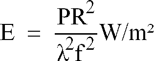
Where P is the power produced by the laser. From this expression the value and purpose of thebeam expander 50 is readily apparant since increasing the radius of the beam R serves to increase the power density E at the focus. In addition, thelens element 78 is typically a short focal length lens having a focal length in the range between 70mm and 80mm so that typical power densities is at the focus of thebeam incident radiation body 26 to melt and reflow leaving a residual mark inscribed upon the surface. By moving the focus of thebeam mirrors 68 and 70 the mark maybe made to a predetermined shape and in particular, maybe made to comprise one or more numerals, letters or symbols or a combination thereof which in turn may represent an identification, a trade mark, a machine readable code or any other desired indicum. - The power density required to stimulate thermal interactions at the surface of the body will, of course, depend upon the material of the body and the speed at which the
beam beam beam beam - In the interests of safety, the two
lasers respective beams safety chamber 80 as shown in Figure 4 with the combinedbeam safety chamber 80 only after passing through thelense assembly 76. Access to the twolasers respective beams door panel 82 which is fitted with aninterlock 84 that prevents the operation of theCO₂ laser 44 while thedoor panel 82 is open. It is to be noted that the He-Ne laser 56 need not necessarily be fitted with an interlock in the same way since it only operates at a very low power and does not represent a significant danger to a skilled operator. - A single phase electrical mains supply of 240V is fed via the
door panel interlock 84 to amains distribution unit 86 that is disposed below, and isolated from, thesafety chamber 80 in order to prevent any electrical effects interfering with the operation of thelasers distribution unit 86 mains electrical power is provided to theCO₂ laser 44 and He-Ne laser 56 as well as to achiller unit 88 that serves to cool theCO₂ laser 44. In addition, mains electrical power is also supplied to the steppingmotor 66 and to acomputer 90. Three AC/DC convertors and associated voltage regulators provide regulated DC voltage supplies of 9v, 12v and 15v that are fed respectively to the He-Ne laser 56 to facilitate the pumping mechanism, to afurther interlock 92 that prevents premature firing of theCO₂ laser 44, and to thehead unit 64 and in particular to the first andsecond galvanometers second mirrors 68 and 70. - The combined operational sequence of the marking
appratus 10 and thesensing module 12 is shown schematically in Figure 5 and commences with thecomputer 90 either calculating or performing a look-up to identify the next mark to be applied. Thus if the laser marking station is used to mark a number of bodies each with a sequential reference number thecomputer 90 may calculate the next mark by adding the necessary increment to the reference number that constitued the previous mark. Alternatively, at the start of a batch or during more complicated marking sequences, thecomputer 90 may identify the next mark from one of a pre-programmed list of marks contained in a suitable memory device. However the next mark is identified, it may be displayed on an operator's console along with other information such as the number of bodies marked in a particular batch, the average line speed of the bodies transported past thesensing module 12 and any other desired information. - Having identified the mark to be applied to the moving
body 26, thecomputer 90 calculates the vectors necessary to trace out the mark assuming thebody 26 to be stationary at the time of marking. These vectors are transformed into an electrical signal that if used to modulate the 15v DC supply applied to the first andsecond galvanometers second mirrors 68 and 70 capable of moving the focus of an actuated laser beam in such a way as to trace out the desired mark. - As the body to be marked is transported to the laser marking station by means of the
conveyor belt 16 the position of the movingbody 26 relative to the fixedside rail 20 may be altered by means of adjustingscrew 24. Typically adjustingscrew 24 is used to narrow the effective width of theconveyor belt 16 adjacent thefirst opening 28 in the protective housing 14. In this way the effective width of theconveyor belt 16 is made not much wider than the movingbody 26 itself thereby providing a degree of control over the lateral distance between the body to be marked and the various components of thesensing module 12 and the markingapparatus 10. - All this time the
sensing module 12 is used to detect the approach of the body to be marked. As thebody 26 reaches opto-detector 32 its leading-edge obstructs the optical path between thelight source 36, the retro-reflector 40 and thedetector 38 causing the quantity of light detected to fall below a preset threshold value. As a result an approriate signal is generated and sent to thecomputer 90 whereupon a clock is actuated. This clock is not stopped until a time t₁ later when the leading-edge of the movingbody 26 is detected in the same way at the second opto-detector 34. Since the two opto-detectors 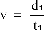
- In order to provide a compact apparatus capable of marking bodies moving at relatively high line speeds, the distance d₁ between the two opto-
detectors detector 34 is caused to abutt opto-detector enabling d₁ to be reduced to a value of 1mm. Even at such small distances the oscillator that forms the basis of the clock is capable of in excess of 5 clock cycles during a typical time interval t₁ so that the reduction in d₁ does not have a discernable effect on the accuracy to which the velocity v maybe measured. - Having passed the second opto-
detector 34, the body to be marked continues to be transported by theconveyor belt 16 until at a time t₂ later it is adjacent the markingapparatus 10. Since the second opto-detector 34 and the markingappartus 10 are again a known distance d₂ apart, the time t₂ maybe calculated by dividing the distance d₂ by the velocity v of the movingbody 26. Thus:
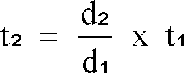
- Again, in order of provide a compact apparatus, the distance d₂ maybe decreased to a minimum ultimately limited by the computing power of the
computer 90 but which is typically of the order of 5mm. - Using the above equation, the
computer 90 calculates the estimated time of arrival t₂ of the body to be marked adjacent the markingapparatus 10. This time interval however represents the time at which the leading-edge of thebody 26 is adjacent the markingapparatus 10 and so, unless the desired mark is to be applied at the leading-edge, a further delay δt is added to the time interval t ₂ to yield a time t₃ at which that portion of thebody 26 to be marked is adjacent the markingapparatus 10. - At a time t₃ after the signal generated by the second opto-
detector 34 theCO₂ laser 44 is actuated and the combined CO₂/He-Ne beam body 26. At the same time an electrical signal is generated to modulate the 15v DC supply applied to the first andsecond galvanometers body 26 at the velocity v. The modulated 15v DC supply produces a series of movements of the first andsecond mirrors 68 and 70 that direct the focus of the combined CO₂/He-Ne beam - After the
body 26 has been marked it continues to be transported by theconveyor belt 16 and passes out the protective housing 14 and away from the laser marking station by way of the second opening 30. Themarked body 26 may thereafter be transported to further processing stations if required whilst thecomputer 90 calculates the next mark to be applied and the operational sequence begins all over again. - It will be apparent to those skilled in the art that as the
body 26 moves past the markingapparatus 10, the distance between thelens assembly 76 and that portion of the surface of thebody 26 that is to marked is subject to constant change. Even if thebody 26 were to be stationary when marked, if the desired mark were of a sufficient size any curvature of thebody 26 would also give rise to differing distances between thelens assembly 76 and various points on the surface. On top of this, successive bodies to be marked may be placed on theconveyor belt 16 at different distances from the fixedside rail 20 despite a narrowing of the effective width of theconveyor belt 16 prior to the laser marking station. If, as has been described, thefirst lens element 78 is of a fixed focal length, each of the above factors will contribute to parts of the mark applied to the body being more or less out of focus. However, with the careful selection of the focal length of thelens element 78 this problem maybe reduced to a minimum. - As has been previously stated, the focal length of the
first lens element 78 is typically between 70mm and 80mm and is capable of focusing the combined CO₂/He-Ne beam lens element 78 has a focal length of 75mm enabling δx for glass to be as large as 5mm, although the size of δx is, of course, dependant upon the material of which thebody 26 is comprised. Using such a lens however, the apparatus described may efficiently mark moving bodies whose surfaces lie within a small range of distances either side of an optimum distance from thelens assembly 76. - Alternatively, or in addition, a
second lens element 92 maybe placed in series with thefirst lens element 78 in order to compensate for one or more of the de-focusing effects described above. Such alens element 92 may posess a focal length that varies across its width and may, for example, comprise a flat field lens so as to compensate for any curvature of the surface of the body to be marked. - In another arrangement, the
lens assembly 76 may include athird lens element 94 in the form of a zoom lens whose focal length may be altered as the body to be marked passes the markingapparatus 10 thereby maintaining the focus of the combined CO₂/He-Ne Beam body 26 inspite of the de-focusing effects described above. - In yet a further arrangement, in place of the
second lens element 92 and or thethird lens element 94 there may be disposed a fourth lens element 95 (not shown) taking the form of a diverging lens. The fourth lens element 95 of focal length f₂ is preferably disposed a distance f₂ in front of the focus that would otherwise be produced by thefirst lens element 78. In this way the fourth lens element 95 produces a narrow parallel beam of high energy density radiation which may be directed at the movingbody 26 to produce an illuminated spot on the surface thereof. Provided that the narrow beam has a sufficient power density it may be used to facilitate the surface marking of the movingbody 26 whilst at the same time not being prone to any of the de-focusing effects described above. - In a second embodiment shown in Figure 6, the marking
apparatus 10 is again designed to facilitate the surface marking of a moving body ofmaterial 26 except that rather than superimposing a component that compensates for that movement on the already complex movement of the first andsecond mirrors 68 and 70, the movement of thebody 26 is entirely compensated for by a fifth reflectingsurface 96. - The fifth reflecting
surface 96 is rotatably mounted about anaxis 98 and is positioned so as to direct on to the movingbody 26 the combined CO₂/He-Ne beam second mirror 70. As the body to be marked passes the markingapparatus 10, the fifth reflectingsurface 96 rotates about theaxis 98 in such a way as to keep the combined CO₂/He-Ne beam body 26. - The fifth reflecting
surface 96 preferably comprises the mirror of a third galavanometer 100 (not shown). In this way the movement of the fifth reflectingsurface 96 may be facilitated with the same speed of response and ease of control as enjoyed by the first andsecond mirrors 68 and 70. Under such circumstances, when theCO₂ laser 44 is actuated and the 15v DC supply applied to the first andsecond galvanometers second mirrors 68 and 70, a separate 15v DC supply may be applied to the third galvanometer 100 and modulated in accordance with the previously measured velocity characteristic of the movingbody 26. As before, the combined effect of the movement of the mirrors of the threegalvanometers body 26 by the combined CO₂/He-Ne beam - In Figure 6 the fifth reflecting
surface 96 is shown disposed between thesecond mirror 70 and thelens assembly 76 although it will be apparent to those skilled in the art that the fifth reflectingsurface 96 may equally well be disposed at other points along the optical path of the combined CO₂/He-Ne beam lens assembly 76. - In a third embodiment which is similar to the second in that the compensation for the movement of the
body 26 is made separately from the generation of the mark itself, the fifth reflectingsurface 96 is replaced by amulti-faceted mirror 102 as shown in Figure 7. As with the fifth reflectingsurface 96, themulti-faceted mirror 102 is rotatably mounted about anaxis 104 and positioned so as to direct on to the movingbody 26 the combined CO₂/He-Ne beam second mirror 70. As the body to be marked passes the markingapparatus 10, themulti-faceted mirror 102 rotates about theaxis 104 in such a way as to keep the combined CO₂/He-Ne beam body 26. - The advantage of this third embodiment as distinct from the second embodiment described above is that once the moving
body 26 has been marked, themulti-faceted mirror 102, unlike the fifth reflectingsurface 96 of the second embodiment, does not need to rotate rapidly about theaxis 104 in either sense in order to be appropriately aligned for the next body to be marked. Instead, themulti-faceted mirror 102 may continue to rotate in the same sense and at such a speed as to enable the combined CO₂/He-Ne beam multi-faceted mirror 102. The shape of themulti-faceted mirror 102 does however impose conditions on its own rotational speed which must be such as to ensure that it does not rotate through an angle greater than that subtended by the operative face during the time taken to mark the movingbody 26. - The rotation of the
multi-faceted mirror 102 may be controlled by thecomputer 90 once the velocity of the movingbody 26 has been measured and the number of vectors required to trace out the desired mark is known since the latter enables a prediction of the necessary marking time while the former permits a calculation of the distance thebody 26 will be transported while being marked. - In Figure 7 the
multi-faceted mirror 102 is shown disposed between thesecond mirror 70 and thelens assembly 76 although it will be apparent to those skilled in the art that themulti-faceted mirror 102 may equally well be disposed at other points along the optical path of the combined CO₂/He-Ne beam lens assembly 76. - In a fourth embodiment of the marking
apparatus 10 shown in Figure 8, the movement of thebody 26 is compensated for by a lateral movement of the entire
head unit 64 andlens assembly 76. Having measured the velocity of the body to be marked, thehead unit 64 andlens assembly 76 is moved in a direction parallel to the movingbody 26 under the action of a motor 106 (not shown). By moving thehead unit 64 andlens assembly 76 at the same velocity as the movingbody 26 the relative velocity between the two may be reduced to zero whilst the desired mark is applied. Once the movingbody 26 has been marked, thehead unit 64 andlens assembly 76 are rapidly returned to their starting positions, again under the action of motor 106 (not shown), so as to be ready for the next body to be marked. - By ensuring that the combined CO₂/He-
Ne beam conveyor belt 16 before being reflected toward the movingbody 26 at thesecond mirror 70, it will be apparent to those skilled in the art that only thesecond mirror 70 and thelens assembly 76 need be moved by the motor 106 (not shown) in order to achieve the desired effect. Indeed, if thelens assembly 76 were disposed in the optical path of the combined CO₂/He-Ne beam surface 60 and the first mirror 68 then only thesecond mirror 70 would need to be moved by the motor 106. - In a fifth embodiment one or more acusto-optic or elctro-optic crystals 108 (not shown) may be disposed in the path of the
beam body 26. Crystals of these types possess the property of being able to deflect an incident beam through different angles depending on the value of a voltage applied thereto. Therefore by applying a suitably varying voltage to the crystals 108 (not shown) the combined CO₂/He-Ne beam body 26 as it passes the markingapparatus 10. - It will also be apparent to those skilled in the art that in the light of the Applicant's co-pending UK Patent Application No. 9117521.6 the apparatus described in relation to any of the foregoing embodiments may also be employed to facilitate the sub-surface marking of a moving body of material without substantial alteration.
- In the past, in order to produce an indelible mark manufacturers have relied almost exclusively on surface marking. However one of the fundamental problems with this type of marking is that it may either be destroyed by removing a part of the surface upon which the mark is applied or imitated by the application of an identical mark on substitute body. By use of apparatus similar to that already described a moving body of material may be provided with a sub-surface mark by directing at the surface of the body a focused beam of high energy density laser radiation to which the material is transparent. The beam is focused at a location spaced from the surface and within the body so as to cause localised ionisation of the material and the creation of a mark in the form of an area of increased opacity to electromagnetic radiation substantially without any detectable change at the surface.
- For the avoidance of doubt, the term transparent as used above with reference to the material to be marked refers to a material in which the high energy density beam can penetrate at least to the depth of the desired mark and as such includes translucent materials and materials such as coloured or smoked glass in which the transmission characteristic to electromagnetic radiation at wavelengths in the visible region has been reduced but not eliminated. The term transparent also includes materials which are opaque to electromagnetic radiation at wavelengths in the visible region but which are at least capable of transmitting electromagnetic radiation at wavelengths within the same region of the electromagnetic spectrum as that of the high energy density beam.
- The possible types of interaction between laser radiation and a body of material may be categorised under three headings dependant upon the power density of the laser radiation concerned. In order of increasing power density these headings are as follows:
- 1. Photochemical interactions including photoinduction and photoactivation;
- 2. Thermal interactions in which the incident radiation is absorbed as heat; and
- 3. Ionising interactions which involve the non-thermal photodecomposition of the irradiated material.
- The difference between the thresholds of these three interactions is clearly demonstrated by comparing the typical power density of 10⁻³ W/cm² required to produce a photochemical interaction with the power density of 10¹² W/cm² typical of ionisation interactions such as photoablation and photodisruption.
- For localised ionisation of the material to take place, the high energy density beam must posess sufficient energy to cleave molecular bonds and create a plasma at the point of focus. Once the beam has been removed, the plasma cools to form a localised zone of damage or disruption which scatters any elctromagnetic radiation that is incident upon it with the result that the zone appears as an area of increased opacity.
- At present, the only commercially available lasers capable of inducing ionisation interactions are pulsed lasers having a peak energy that, when focused, is sufficient to create a plasma within the material concerned. In order to facilitate the sub-surface marking of a moving body therefore the
source 48 oflaser radiation 50 is preferably replaced by a laser having a power density at its focus of at least 10⁷ W/cm² and a pulse duration of no more than 10⁻⁶ seconds. In this way the energy density of each pulse is at least 10 J/cm² and sufficient to induce localised ionisation of the material at the focus of the beam. - If the sub-surface mark is to be visible to the naked eye the body to be marked must be transparent to electromagnetic radiation at wavelengths within the visible region. For example, the body may be of glass or plastics. The body to be marked however need not necessarily be limited in this way and may comprise a material that is opaque to elctromagnetic radiation at wavelengths within the visible region. Under these circumstances the resulting sub-surface mark is hidden to the naked eye but maybe "seen" by optical instruments operating at an appropriate wavelength within the elctromagnetic spectrum such as that of the high energy density beam. While such a mark is not capable of performing many of the functions of its visible counterpart, it does represent a truly indelible covert mark.
- Assuming that the eventual sub-surface mark is intended to be visible to the naked eye and that therefore the moving
body 26 is of a material such as glass or plastics that are transparent to elctromagnetic radiation within the visible region of the elctromagentic spectrum, thesource 48, in addition to the power constraints identified above, must also be selected so that the material of thebody 26 is transparent to thelaser radiation 50 that it produces. Under these circumstances thesource 48 preferably comprises a Nd-YAG (Neodymium-doped Yttrium Aluminium Garnet) laser operating at a wavelength of 1.06µm. - The remainder of the apparatus described need not be substantially altered in order to facilitate sub-surface marking although the selection of the
source 40 will of course have an effect on the choice of the optical elements used to direct and focus the resulting laser radiating 50 since not all such elements will operate with the same efficiency at different wavelengths within the elctromagnetic spectrum. It is however considered that the appropriate selection of elements falls within the ordinary expertise of one skilled in the art. - When employed to facilitate the sub-surface marking of a moving body, the
lens assembly 76 may include athird lens element 94 in the form of a zoom lens so that marks maybe made at different depths within the movingbody 26 and so allow for the creation of three dimensional marks. - It will be apparant to those skilled in the art that while the apparatus described includes means for determining the velocity of the moving
body 26 this need not necessarily be so since a mechanical linkage may be incorporated in to the apparatus that imparts to the combined CO₂/He-Ne beam 46,58 a component of movement equal to the velocity of the movingbody 26 without ever determining what that velocity is.
Claims (36)
- A method of marking a moving body of material comprising the steps of directing at the moving body a high energy density beam, concentrating the beam so as to produce an illuminated spot at a location on or within the moving body, and moving said spot in accordance with the resultant of two components of movement, the first being equal to the velocity of the moving body and the second being relative to the moving body so as to create a mark of a predetermined shape.
- A method in accordance with claim 1, wherein there is included the additional step of determining the velocity of the moving body.
- A method in accordance with claim 2, wherein the velocity of the moving body is determined by means of direct measurement.
- A method in accordance with any preceding claim, wherein the high energy density beam is directed at the moving body by causing the path of the moving body to intersect the path of the actuated high energy density beam and actuating the high energy denisty beam at a predetermined time after the moving body passes a position a known distance from the point of intersection, that time being dependant upon the velocity of the moving body.
- A method in accordance with any preceding claim, wherein the high energy density beam is brought to a focus at a location within the moving body so as to cause localised ionisation of the material and the creation of a mark in the form of an area of increased opacity to electromagnetic radiation.
- A method in accordance with claim 5, wherein the moving body of material is transparent to electromagnetic radiation at wavelengths within the visible region.
- A method in accordance with claim 5, wherein the moving body of material is opaque to electromagnetic radiation at wavelengths within the visible region.
- A method in accordance with any preceding claim, wherein the mark comprises one or more numerals, letters, or symbols, or a combination thereof.
- A method in accordance with any preceding claim, wherein the mark is three dimensional.
- An apparatus for marking a moving body of material comprising means for creating a high energy density beam and directing the beam at the moving body, means for concentrating the beam so as to produce an illuminated spot at a location on or within the moving body and means for moving said spot in accordance with the resultant of two components of movement, the first being equal to the velocity of the moving body and the second being relative to the moving body so as to create a mark of a predetermined shape.
- An apparatus in accordance with claim 10, wherein the means for moving said spot in accordance with the resultant of two components of movement includes means for moving the spot in accordance with the said second of the two components.
- An apparatus in accordance with claim 11, wherein the means for moving the spot in accordance with the said second of the two components includes at least one moveable mirror disposed in the path of the beam.
- An apparatus in accordance with claim 12, wherein the movement of the said at least one moveable mirror is controlled in accordance with a computer program.
- An apparatus in accordance with claim 12 or claim 13, wherein the said at least one moveable mirror is a galvanometer mirror.
- An apparatus in accordance with any of claims 11 to 14, wherein the means for moving the spot in accordance with the said second of the two components is also capable of moving the spot in accordance with the said first of the two components.
- An apparatus in accordance with any of claims 11 to 14, wherein the means for moving said spot in accordance with the resultant of two components of movement includes additional means for moving the spot in accordance with the said first of the two components.
- An apparatus in accordance with claim 16, wherein the means for moving the spot in accordance with the said first of the two components includes at least one rotatably mounted mirror whose speed of rotation is varied in accordance with the velocity of the moving body.
- An apparatus in accordance with claim 17, wherein the said at least one rotatably mounted mirror is multi-faceted.
- An apparatus in accordance with claim 16, wherein the means for moving the spot in accordance with the said first of the two components includes at least one mirror moveable at the same velocity as the moving body.
- An apparatus in accordance with claim 16, wherein the means for moving the spot in accordance with the said first of the two components includes at least one acusto-optic or elctro-optic crystal.
- An apparatus in accordance with any of claims 10 to 20, wherein there is further provided means for determining the velocity of the moving body.
- An apparatus in accordance with claim 21, wherein the velocity of the moving body is determined by means of direct measurement.
- An apparatus in accordance with claim 22, wherein the velocity of the moving body is determined by measuring the time taken for the moving body to travel between two opto-detectors spaced a known distance apart.
- An apparatus in accordance with any of claims 10 to 23, wherein the high energy density beam is directed at the moving body by causing the path of the moving body to intersect the path of the high energy beam when actuated and providing means to actuate the high energy density beam at a predetermined time after the moving body passes a position a known distance from the point of intersection, that time being dependant upon the velocity of the moving body.
- An apparatus in accordance with any of claims 10 to 24, wherein the means for concentrating the beam includes a lens element having a focal length that varies across its width.
- An apparatus in accordance with any of claims 10 to 2 5, wherein the means for concentrating the beam includes a zoom lens.
- An apparatus in accordance with any of claims 10 to 24, wherein the means for concentrating the beam includes a diverging lens.
- An apparatus in accordance with any of claims 10 to 27, wherein the mark comprises a surface mark.
- An apparatus in accordance with claim 28, wherein the means for creating a high energy density beam comprises a CO₂ laser.
- An apparatus in accordance with any of claims 10 to 26, wherein the mark comprises a sub-surface mark.
- An apparatus in accordance with claim 30, wherein the means for creating a high energy density beam comprises a laser which is focused so as to have a peak energy density at the focus of at least 10 J/cm².
- An apparatus in accordance with claim 30 or claim 31, wherein the means for creating a high energy density beam comprises a laser which is focused so as to have a power density at the focus of at least 10⁷ W/cm² and is pulsed with a pulse duration of at least 10⁻⁶ seconds.
- An apparatus in accordance with any of claims 30 to 32, wherein the means for creating a high energy density beam comprises a Nd-YAG laser.
- An apparatus in accordance with any of claims 10 to 33, wherein there is further provided a secondary source of visible laser radiation to facilitate alignment of the high energy density beam.
- An apparatus in accordance with any of claims 10 to 34 wherein a conveyor belt is provided ,to transport said moving body.
- An apparatus in accordance with claim 35, wherein means are provided to control the lateral position of the moving body relative to the conveyor belt.
Applications Claiming Priority (6)
| Application Number | Priority Date | Filing Date | Title |
|---|---|---|---|
| GB9101063 | 1991-01-17 | ||
| GB919101063A GB9101063D0 (en) | 1991-01-17 | 1991-01-17 | Laser marking |
| GB919109935A GB9109935D0 (en) | 1991-01-17 | 1991-05-08 | Laser marking |
| GB9109935 | 1991-05-08 | ||
| GB9123609 | 1991-11-05 | ||
| GB9123609A GB2252068B (en) | 1991-01-17 | 1991-11-05 | Dynamic laser marking |
Publications (2)
| Publication Number | Publication Date |
|---|---|
| EP0495647A1 true EP0495647A1 (en) | 1992-07-22 |
| EP0495647B1 EP0495647B1 (en) | 1997-05-02 |
Family
ID=27265459
Family Applications (1)
| Application Number | Title | Priority Date | Filing Date |
|---|---|---|---|
| EP92300350A Expired - Lifetime EP0495647B1 (en) | 1991-01-17 | 1992-01-15 | Dynamic laser marking |
Country Status (21)
| Country | Link |
|---|---|
| US (1) | US5653900A (en) |
| EP (1) | EP0495647B1 (en) |
| JP (1) | JP2863872B2 (en) |
| AT (1) | ATE152387T1 (en) |
| AU (1) | AU659131B2 (en) |
| BG (1) | BG60904B1 (en) |
| CA (1) | CA2100550C (en) |
| CZ (1) | CZ141893A3 (en) |
| DE (1) | DE69219370T2 (en) |
| DK (1) | DK0495647T3 (en) |
| ES (1) | ES2102455T3 (en) |
| FI (1) | FI105326B (en) |
| GR (1) | GR3024276T3 (en) |
| HK (1) | HK1007118A1 (en) |
| HU (1) | HU217738B (en) |
| IE (1) | IE71928B1 (en) |
| NO (1) | NO308240B1 (en) |
| PL (1) | PL169904B1 (en) |
| RO (1) | RO110428B1 (en) |
| SK (1) | SK74493A3 (en) |
| WO (1) | WO1992012820A1 (en) |
Cited By (9)
| Publication number | Priority date | Publication date | Assignee | Title |
|---|---|---|---|---|
| US5605641A (en) * | 1992-11-25 | 1997-02-25 | Komatsu Ltd. | Method and apparatus for laser marking a continuously moving workpiece |
| US5801868A (en) * | 1993-11-19 | 1998-09-01 | Komatsu Ltd. | Apparatus for and method of laser making |
| DE19946080C2 (en) * | 1998-10-06 | 2002-02-14 | Fraunhofer Ges Forschung | Test bottle and process for its manufacture |
| DE102006022492A1 (en) * | 2006-05-13 | 2007-11-22 | Krones Ag | Test container and test arrangement for a container control device |
| WO2008047058A2 (en) * | 2006-10-18 | 2008-04-24 | Tiama | Process and installation for the hot marking of translucent or transparent objects |
| EP3269829A1 (en) * | 2016-07-13 | 2018-01-17 | SLCR Lasertechnik GMBH | Method and device for applying a code to an untreated or treated animal skin |
| US10583668B2 (en) | 2018-08-07 | 2020-03-10 | Markem-Imaje Corporation | Symbol grouping and striping for wide field matrix laser marking |
| FR3087367A1 (en) | 2018-10-22 | 2020-04-24 | Tiama | METHOD AND INSTALLATION FOR MARKING HOT GLASS CONTAINERS |
| EP4197683A1 (en) * | 2021-11-15 | 2023-06-21 | Ricoh Company, Ltd. | Laser processing apparatus and laser processing method |
Families Citing this family (114)
| Publication number | Priority date | Publication date | Assignee | Title |
|---|---|---|---|---|
| GB2281129B (en) * | 1993-08-19 | 1997-04-09 | United Distillers Plc | Method of marking a body of glass |
| US5658474A (en) * | 1994-12-16 | 1997-08-19 | Alza Corporation | Method and apparatus for forming dispenser delivery ports |
| US6298275B1 (en) * | 1995-03-23 | 2001-10-02 | Gerber Garment Technology, Inc. | Non-intrusive part identification system for parts cut from a sheet material |
| US5937270A (en) | 1996-01-24 | 1999-08-10 | Micron Electronics, Inc. | Method of efficiently laser marking singulated semiconductor devices |
| WO1997040957A1 (en) * | 1996-04-26 | 1997-11-06 | Servicio Industrial De Marcaje Y Codificacion, S.A. | System and process for marking or perforating |
| US5837962A (en) * | 1996-07-15 | 1998-11-17 | Overbeck; James W. | Faster laser marker employing acousto-optic deflection |
| FR2762425B1 (en) * | 1997-04-18 | 1999-06-04 | Chevillot Sa | INFALSIFIABLE, INDELEBILE AND CONTRAST MARKING OF OBJECTS AND PARTICULARLY LABELS |
| US6926487B1 (en) | 1998-04-28 | 2005-08-09 | Rexam Ab | Method and apparatus for manufacturing marked articles to be included in cans |
| US6706995B2 (en) * | 1998-07-16 | 2004-03-16 | Ball Corporation | Laser light marking of a container portion |
| US6080958A (en) * | 1998-07-16 | 2000-06-27 | Ball Corporation | Method and apparatus for marking containers using laser light |
| US6417484B1 (en) | 1998-12-21 | 2002-07-09 | Micron Electronics, Inc. | Laser marking system for dice carried in trays and method of operation |
| US6262388B1 (en) | 1998-12-21 | 2001-07-17 | Micron Electronics, Inc. | Laser marking station with enclosure and method of operation |
| US6479787B1 (en) | 1999-10-05 | 2002-11-12 | Rexam Ab | Laser unit and method for engraving articles to be included in cans |
| US6469729B1 (en) * | 1999-10-15 | 2002-10-22 | Videojet Technologies Inc. | Laser marking device and method for marking arcuate surfaces |
| US6281471B1 (en) * | 1999-12-28 | 2001-08-28 | Gsi Lumonics, Inc. | Energy-efficient, laser-based method and system for processing target material |
| US7838794B2 (en) | 1999-12-28 | 2010-11-23 | Gsi Group Corporation | Laser-based method and system for removing one or more target link structures |
| US7671295B2 (en) * | 2000-01-10 | 2010-03-02 | Electro Scientific Industries, Inc. | Processing a memory link with a set of at least two laser pulses |
| US6872913B1 (en) | 2000-01-14 | 2005-03-29 | Rexam Ab | Marking of articles to be included in cans |
| US6455806B1 (en) | 2000-01-14 | 2002-09-24 | Rexam Ab | Arrangement for shaping and marking a target |
| US6926456B1 (en) | 2000-01-20 | 2005-08-09 | Rexam Ab | Guiding device for a marking arrangement |
| AU2001232949A1 (en) * | 2000-01-28 | 2001-08-07 | Gsi Lumonics Inc. | Laser scanning method and system for marking articles such as printed circuit boards, integrated circuits and the like |
| US20030024913A1 (en) * | 2002-04-15 | 2003-02-06 | Downes Joseph P. | Laser scanning method and system for marking articles such as printed circuit boards, integrated circuits and the like |
| US6576871B1 (en) | 2000-04-03 | 2003-06-10 | Rexam Ab | Method and device for dust protection in a laser processing apparatus |
| US6791592B2 (en) | 2000-04-18 | 2004-09-14 | Laserink | Printing a code on a product |
| US6417485B1 (en) * | 2000-05-30 | 2002-07-09 | Igor Troitski | Method and laser system controlling breakdown process development and space structure of laser radiation for production of high quality laser-induced damage images |
| US6528760B1 (en) | 2000-07-14 | 2003-03-04 | Micron Technology, Inc. | Apparatus and method using rotational indexing for laser marking IC packages carried in trays |
| AU2001296283A1 (en) * | 2000-09-21 | 2002-04-02 | Gsi Lumonics Corporation | Digital control servo system |
| US8497450B2 (en) | 2001-02-16 | 2013-07-30 | Electro Scientific Industries, Inc. | On-the fly laser beam path dithering for enhancing throughput |
| US7245412B2 (en) | 2001-02-16 | 2007-07-17 | Electro Scientific Industries, Inc. | On-the-fly laser beam path error correction for specimen target location processing |
| US6639177B2 (en) * | 2001-03-29 | 2003-10-28 | Gsi Lumonics Corporation | Method and system for processing one or more microstructures of a multi-material device |
| US6768504B2 (en) * | 2001-03-31 | 2004-07-27 | Videojet Technologies Inc. | Device and method for monitoring a laser-marking device |
| US6538230B2 (en) * | 2001-05-17 | 2003-03-25 | Preco Laser Systems, Llc | Method and apparatus for improving laser hole resolution |
| US6809288B2 (en) * | 2001-05-23 | 2004-10-26 | Osmotica Corp. | Laser drilling system and method |
| DE10146820B4 (en) * | 2001-09-19 | 2005-02-24 | Tampoprint Gmbh | Decorating device and method for decorating surfaces |
| WO2003046613A2 (en) * | 2001-11-28 | 2003-06-05 | Overbeck James W | Scanning microscopy, fluorescence detection, and laser beam positioning |
| KR100982677B1 (en) * | 2002-01-11 | 2010-09-17 | 일렉트로 싸이언티픽 인더스트리이즈 인코포레이티드 | Method for laser machining a workpiece with laser spot enlargement |
| US6706998B2 (en) | 2002-01-11 | 2004-03-16 | Electro Scientific Industries, Inc. | Simulated laser spot enlargement |
| US7396441B2 (en) | 2002-02-22 | 2008-07-08 | Aqua Innovations, Inc. | Flow-through oxygenator |
| USRE47092E1 (en) | 2002-02-22 | 2018-10-23 | Oxygenator Water Technologies, Inc. | Flow-through oxygenator |
| US7169685B2 (en) | 2002-02-25 | 2007-01-30 | Micron Technology, Inc. | Wafer back side coating to balance stress from passivation layer on front of wafer and be used as die attach adhesive |
| US7204884B2 (en) * | 2002-03-22 | 2007-04-17 | Agc Automotive Americas Co. | Laser marking system |
| US6951995B2 (en) * | 2002-03-27 | 2005-10-04 | Gsi Lumonics Corp. | Method and system for high-speed, precise micromachining an array of devices |
| US7563695B2 (en) * | 2002-03-27 | 2009-07-21 | Gsi Group Corporation | Method and system for high-speed precise laser trimming and scan lens for use therein |
| US6670576B2 (en) * | 2002-04-08 | 2003-12-30 | Igor Troitski | Method for producing images containing laser-induced color centers and laser-induced damages |
| US6617543B1 (en) * | 2002-04-11 | 2003-09-09 | Shih-Sheng Yang | Method of making pattern for decorative piece |
| US20050044895A1 (en) * | 2002-04-16 | 2005-03-03 | Central Glass Company, Limited | Method for putting color to glass or erasing color from colored glass |
| US6664501B1 (en) * | 2002-06-13 | 2003-12-16 | Igor Troitski | Method for creating laser-induced color images within three-dimensional transparent media |
| US7011880B2 (en) * | 2002-07-03 | 2006-03-14 | The Gates Corporation | Belt and method of marking |
| US6720523B1 (en) * | 2002-09-23 | 2004-04-13 | Igor Troitski | Method for production of laser-induced images represented by incomplete data, which are supplemented during production |
| US20040091588A1 (en) * | 2002-10-31 | 2004-05-13 | Xiaochun Li | Food processing apparatus and method |
| US7951409B2 (en) | 2003-01-15 | 2011-05-31 | Newmarket Impressions, Llc | Method and apparatus for marking an egg with an advertisement, a freshness date and a traceability code |
| US6706999B1 (en) | 2003-02-24 | 2004-03-16 | Electro Scientific Industries, Inc. | Laser beam tertiary positioner apparatus and method |
| US6740846B1 (en) | 2003-03-27 | 2004-05-25 | Igor Troitski | Method for production of 3D laser-induced head image inside transparent material by using several 2D portraits |
| GB0313887D0 (en) * | 2003-06-16 | 2003-07-23 | Gsi Lumonics Ltd | Monitoring and controlling of laser operation |
| EP1704017A1 (en) * | 2003-12-18 | 2006-09-27 | Retainagroup Limited | Portable laser apparatus for marking an object |
| US7046267B2 (en) * | 2003-12-19 | 2006-05-16 | Markem Corporation | Striping and clipping correction |
| US20050165590A1 (en) * | 2004-01-23 | 2005-07-28 | Yuhong Huang | System and method for virtual laser marking |
| US20060091124A1 (en) * | 2004-11-02 | 2006-05-04 | Igor Troitski | Method for transformation of color images into point arrangement for production of laser-induced color images inside transparent materials |
| US7612312B2 (en) * | 2005-02-11 | 2009-11-03 | Honeywell International Inc. | Mobile hand-held laser welding support system |
| US7318778B2 (en) * | 2005-06-11 | 2008-01-15 | Owens Mark R | Golf putter with removable laser |
| US20070215575A1 (en) * | 2006-03-15 | 2007-09-20 | Bo Gu | Method and system for high-speed, precise, laser-based modification of one or more electrical elements |
| US8084706B2 (en) * | 2006-07-20 | 2011-12-27 | Gsi Group Corporation | System and method for laser processing at non-constant velocities |
| WO2008091380A2 (en) * | 2006-08-22 | 2008-07-31 | Gsi Group Corporation | System and method for employing a resonant scanner in an x-y high speed drilling system |
| US8084712B2 (en) * | 2007-03-16 | 2011-12-27 | TEN Medias LLC | Method and apparatus for laser marking objects |
| KR101516742B1 (en) * | 2007-09-19 | 2015-05-04 | 엘렉트로 사이언티픽 인더스트리즈 인코포레이티드 | Link processing with high speed beam deflection |
| FI20075824L (en) * | 2007-11-21 | 2009-05-22 | Outotec Oyj | Method of Feeding Material Streams from a Preheating Furnace to a Melting Furnace and Preheating System |
| ES2336987B1 (en) * | 2007-12-31 | 2011-03-22 | ON-LASER SYSTEMS & APPLICATIONS, S.L. | ROTATING MARKING PROCEDURE AND DEVICE. |
| DE102008011808B4 (en) * | 2008-02-29 | 2012-11-15 | Zwiesel Kristallglas Aktiengesellschaft | Method and apparatus for removing the glass seams with polishing the seams and thereby processed glass product |
| DE102008028376A1 (en) * | 2008-06-13 | 2009-12-17 | Krones Ag | Apparatus and method for marking plastic containers |
| JP2010155258A (en) * | 2008-12-26 | 2010-07-15 | Toray Eng Co Ltd | Substrate processing device |
| TWI454687B (en) * | 2009-08-03 | 2014-10-01 | Toray Eng Co Ltd | Marking device and method |
| US8212178B1 (en) * | 2009-09-28 | 2012-07-03 | Klein Tools, Inc. | Method and system for marking a material using a laser marking system |
| US8785811B2 (en) * | 2009-09-29 | 2014-07-22 | Preco, Inc. | System and method for efficient laser processing of a moving web-based material |
| KR20120113245A (en) * | 2009-12-30 | 2012-10-12 | 지에스아이 그룹 코포레이션 | Link processing with high speed beam deflection |
| US8715757B2 (en) * | 2010-01-20 | 2014-05-06 | Ten Media, Llc | Systems and methods for processing eggs |
| US20110177208A1 (en) * | 2010-01-20 | 2011-07-21 | Newmarket Impressions, Llc | Systems and methods for processing eggs |
| US8657098B2 (en) * | 2010-01-20 | 2014-02-25 | Ten Media, Llc | Systems and methods for processing eggs |
| US8499718B2 (en) * | 2010-01-20 | 2013-08-06 | Ten Media, Llc | Systems and methods for processing eggs |
| US8823758B2 (en) | 2010-01-20 | 2014-09-02 | Ten Media, Llc | Systems and methods for processing eggs |
| US8455030B2 (en) * | 2010-01-20 | 2013-06-04 | Ten Media, Llc | Systems and methods for processing eggs |
| NZ601476A (en) | 2010-01-20 | 2014-07-25 | Ten Media Llc | Systems and methods for processing eggs and other objects |
| US8455026B2 (en) | 2010-01-20 | 2013-06-04 | Ten Media, Llc | Systems and methods for processing eggs |
| ES2380480B8 (en) | 2010-04-21 | 2013-11-14 | Macsa Id, S.A. | DEVICE AND PROCEDURE TO MARK THROUGH LASER A MOVING OBJECT. |
| US9217731B2 (en) | 2010-05-21 | 2015-12-22 | Kabushiki Kaisha Toshiba | Welding inspection method and apparatus thereof |
| US20110284508A1 (en) * | 2010-05-21 | 2011-11-24 | Kabushiki Kaisha Toshiba | Welding system and welding method |
| JP5393598B2 (en) * | 2010-06-03 | 2014-01-22 | キヤノン株式会社 | Galvano device and laser processing device |
| JP5641835B2 (en) * | 2010-09-10 | 2014-12-17 | 株式会社ディスコ | Split method |
| US20130001237A1 (en) * | 2011-06-29 | 2013-01-03 | Marsh Dennis R | Glass Container Having Sub-Surface Wall Decoration and Method of Manufacture |
| ES2438751T3 (en) | 2011-09-05 | 2014-01-20 | ALLTEC Angewandte Laserlicht Technologie Gesellschaft mit beschränkter Haftung | Device and procedure for marking an object by means of a laser beam |
| EP2565994B1 (en) | 2011-09-05 | 2014-02-12 | ALLTEC Angewandte Laserlicht Technologie Gesellschaft mit beschränkter Haftung | Laser device and method for marking an object |
| EP2564972B1 (en) * | 2011-09-05 | 2015-08-26 | ALLTEC Angewandte Laserlicht Technologie Gesellschaft mit beschränkter Haftung | Marking apparatus with a plurality of lasers, deflection means and telescopic means for each laser beam |
| ES2530070T3 (en) * | 2011-09-05 | 2015-02-26 | ALLTEC Angewandte Laserlicht Technologie Gesellschaft mit beschränkter Haftung | Marking apparatus with a plurality of individually adjustable lasers and sets of deflection means |
| DK2564973T3 (en) * | 2011-09-05 | 2015-01-12 | Alltec Angewandte Laserlicht Technologie Ges Mit Beschränkter Haftung | Marking apparatus having a plurality of lasers and a kombineringsafbøjningsindretning |
| DK2565996T3 (en) | 2011-09-05 | 2014-01-13 | Alltec Angewandte Laserlicht Technologie Gmbh | Laser device with a laser unit and a fluid container for a cooling device of the laser unit |
| EP2564974B1 (en) * | 2011-09-05 | 2015-06-17 | ALLTEC Angewandte Laserlicht Technologie Gesellschaft mit beschränkter Haftung | Marking apparatus with a plurality of gas lasers with resonator tubes and individually adjustable deflection means |
| EP2564976B1 (en) | 2011-09-05 | 2015-06-10 | ALLTEC Angewandte Laserlicht Technologie Gesellschaft mit beschränkter Haftung | Marking apparatus with at least one gas laser and heat dissipator |
| US9315317B2 (en) | 2012-02-21 | 2016-04-19 | Ten Media, Llc | Container for eggs |
| CN104245332B (en) * | 2012-04-20 | 2016-12-28 | 芬欧汇川集团 | For the method and apparatus manufacturing the marking in mobile web |
| US8967839B2 (en) | 2012-05-23 | 2015-03-03 | Continental Automotive Systems, Inc. | Instrument cluster illuminated display element |
| US9789462B2 (en) | 2013-06-25 | 2017-10-17 | The Boeing Company | Apparatuses and methods for accurate structure marking and marking-assisted structure locating |
| FR3007678B1 (en) * | 2013-06-28 | 2015-07-31 | Essilor Int | METHOD FOR MANUFACTURING AN OPHTHALMIC LENS COMPRISING A LASER MARKING STEP FOR REALIZING PERMANENT ENGRAVINGS ON A SURFACE OF THE OPHTHALMIC LENS |
| US9782796B2 (en) * | 2013-07-30 | 2017-10-10 | Owens-Brockway Glass Container Inc. | Selective color striking of color-strikable articles |
| EP2886242B1 (en) * | 2013-12-20 | 2016-09-14 | TRUMPF Werkzeugmaschinen GmbH + Co. KG | Laser processing machine assembly, in particular with barrier free access |
| FR3019074B1 (en) * | 2014-04-01 | 2016-04-15 | Snecma | METHOD FOR SURFACE MARKING A MECHANICAL PIECE BY PREDEFINED GRAPHICAL REPRESENTATION WITH HOLOGRAPHIC TYPE EFFECT |
| JP6137099B2 (en) * | 2014-09-29 | 2017-05-31 | ブラザー工業株式会社 | Laser processing apparatus and control program |
| BR112017021873B1 (en) | 2015-04-17 | 2022-09-13 | Ball Corporation | APPARATUS FOR CONTROLLING THE INPUT AND OUTPUT SPEED OF A CONTINUOUS SHEET OF TONGUE MATERIAL, FIRST APPARATUS AND METHOD OF CONTROLLING AN INPUT RATE AND AN OUTPUT RATE ON A CONTINUOUS SHEET OF MATERIAL |
| US10421111B2 (en) | 2015-04-17 | 2019-09-24 | Ball Corporation | Method and apparatus for controlling an operation performed on a continuous sheet of material |
| ES2603751B9 (en) * | 2015-08-28 | 2018-03-09 | Macsa Id, S.A. | Procedure for manufacturing equipment for marking products by laser on demand, and equipment for marking products by laser obtained with said procedure |
| RU2746048C2 (en) | 2016-05-31 | 2021-04-06 | Корнинг Инкорпорейтед | Anti-counterfeiting measures for glass products |
| TR201607270A1 (en) * | 2016-05-31 | 2017-12-21 | Tuerkiye Sise Ve Cam Fabrikalari Anonim Sirketi | A GLASSWARE PROCESSING METHOD AND A SYSTEM USING THIS METHOD |
| JP6847885B2 (en) * | 2018-03-20 | 2021-03-24 | 株式会社東芝 | Information processing equipment, information processing methods and programs |
| EP4025541A4 (en) * | 2019-09-06 | 2022-10-12 | Mobile Advanced Technologies, LLC | Glass separating and cutting system for electronic mobile device repair |
| US20230278141A1 (en) * | 2020-08-20 | 2023-09-07 | Keiichi Serizawa | Pattern forming apparatus |
| JP2022129829A (en) * | 2021-02-25 | 2022-09-06 | 株式会社リコー | Marking device, medium, storage body and marking method |
Citations (7)
| Publication number | Priority date | Publication date | Assignee | Title |
|---|---|---|---|---|
| US4063064A (en) * | 1976-02-23 | 1977-12-13 | Coherent Radiation | Apparatus for tracking moving workpiece by a laser beam |
| EP0168351A1 (en) * | 1984-07-10 | 1986-01-15 | Lasarray Holding Ag | Laser pattern generator and process for using it |
| EP0176872A1 (en) * | 1984-09-25 | 1986-04-09 | Siemens Aktiengesellschaft | Appliance for the contactless changing of the surfaces of objects |
| US4758703A (en) * | 1987-05-06 | 1988-07-19 | Estee Lauder Inc. | System and method for encoding objects |
| WO1990000459A1 (en) * | 1988-07-07 | 1990-01-25 | Grundfos International A/S | A method of processing an article by means of a laser beam |
| EP0400476A2 (en) * | 1989-05-29 | 1990-12-05 | Siemens Aktiengesellschaft | Laser machining device |
| EP0402298A2 (en) * | 1989-06-07 | 1990-12-12 | Codilaser S.A. | A system for marking moving objects by laser beams |
Family Cites Families (82)
| Publication number | Priority date | Publication date | Assignee | Title |
|---|---|---|---|---|
| FR1561258A (en) * | 1968-01-15 | 1969-03-28 | ||
| CA991277A (en) * | 1972-07-03 | 1976-06-15 | David Sciaky | Laser beam manipulator and protective system |
| US3848104A (en) * | 1973-04-09 | 1974-11-12 | Avco Everett Res Lab Inc | Apparatus for heat treating a surface |
| US4049945A (en) * | 1973-10-10 | 1977-09-20 | Winkler & Dunnebier Maschinenfabrik Und Eisengiesserei Kg | Method of and apparatus for cutting material to shape from a moving web by burning |
| GB1450251A (en) * | 1974-01-08 | 1976-09-22 | Reed Irrigation Systems | Creating holes in members |
| GB1478759A (en) * | 1974-11-18 | 1977-07-06 | Alza Corp | Process for forming outlet passageways in pills using a laser |
| GB1541214A (en) * | 1974-12-11 | 1979-02-28 | Atomic Energy Authority Uk | Optical apparatus |
| US4160894A (en) * | 1975-05-14 | 1979-07-10 | Winkler & Dunnebier Maschinenfabrik Und Eisengiesserei Kg | Method and apparatus for the focal form cutting of a moving web of material by a laser beam |
| US4099830A (en) * | 1976-12-15 | 1978-07-11 | A. J. Bingley Limited | Optical systems including polygonal mirrors rotatable about two axes |
| US4100599A (en) * | 1976-12-22 | 1978-07-11 | Ncr Canada Ltd. - Ncr Canada Ltee | Method and apparatus for determining velocity of a moving member |
| US4154530A (en) * | 1977-12-22 | 1979-05-15 | National Semiconductor Corporation | Laser beam error correcting process |
| NO790519L (en) * | 1978-06-21 | 1979-12-27 | Ahlstroem Oy | SPIRAL WRAPPED SLEEVE, METHOD FOR MANUFACTURING THE SLEEVE, PROCEDURE FOR USING THE SLEEVE IN A WRAPPING APPLIANCE AND DEVICE FOR USING THE SLEEVE |
| US4404454A (en) * | 1978-09-20 | 1983-09-13 | Philip Morris Incorporated | Light energy perforation apparatus and system |
| US4218606A (en) * | 1978-10-03 | 1980-08-19 | Olin Corporation | Apparatus for perforating webs with high intensity, coherent radiation |
| DE2853258A1 (en) * | 1978-12-09 | 1980-06-12 | Hoesch Werke Ag | METHOD AND ARRANGEMENT FOR APPLYING A MARKING ON THE SURFACE OF MOVING TABLES AND TAPES |
| US4283145A (en) * | 1979-02-13 | 1981-08-11 | Kirin Beer Kabushiki Kaisha | Optical system for the detection of flaws in bottles or the like |
| US4323755A (en) * | 1979-09-24 | 1982-04-06 | Rca Corporation | Method of making a machine-readable marking in a workpiece |
| US4371782A (en) * | 1979-12-31 | 1983-02-01 | Frans Brouwer | Optical pattern tracing system with remotely controlled kerf and forward offsets |
| GB2073639A (en) * | 1980-02-20 | 1981-10-21 | Duracell Int | Apparatus and method for spot heat treating workpieces |
| US4375025A (en) * | 1980-06-19 | 1983-02-22 | Automated Industrial Systems, Inc. | Laser strip marker |
| CS214081B1 (en) * | 1980-06-26 | 1982-04-09 | Peter Urbanek | Method of glass products surface treatment by means of infrared radiation of laser and apparatus for making the same |
| US4338114A (en) * | 1980-08-21 | 1982-07-06 | Liberty Glass Company | Laser treatment method for imparting increased mechanical strength to glass objects |
| JPS5935892A (en) * | 1982-08-20 | 1984-02-27 | Nec Corp | Laser working device |
| US4560856A (en) * | 1982-09-01 | 1985-12-24 | Westinghouse Electric Corp. | Pulsed laser machining apparatus |
| IL66817A0 (en) * | 1982-09-16 | 1982-12-31 | Gaz Moshe | Special visual and sound effects in cinematography using beam lasers on positive and negative copies |
| US4480169A (en) * | 1982-09-13 | 1984-10-30 | Macken John A | Non contact laser engraving apparatus |
| NL8204604A (en) * | 1982-11-26 | 1984-06-18 | Wavin Bv | PLASTIC MATERIAL. |
| GB2131417B (en) * | 1982-12-02 | 1987-04-08 | Western Electric Co Ltd | Optical device and preform fabrication |
| IL67599A (en) * | 1982-12-31 | 1986-09-30 | Laser Ind Ltd | Control apparatus particularly useful for controlling a laser |
| DE3333386A1 (en) * | 1983-09-15 | 1985-04-11 | Siemens AG, 1000 Berlin und 8000 München | METHOD AND DEVICE FOR LABELING PARTS, ESPECIALLY ELECTRONIC COMPONENTS |
| FR2553910B1 (en) * | 1983-10-24 | 1986-03-21 | Commissariat Energie Atomique | THERMOELECTRIC SENSOR FOR LASER BEAM ALIGNMENT AND SERVO DEVICE USING THE SAME, FOR AUTOMATIC ALIGNMENT OF A LASER BEAM |
| DE3406677A1 (en) * | 1984-02-24 | 1985-09-05 | Fa. Carl Zeiss, 7920 Heidenheim | DEVICE FOR COMPENSATING THE EMISSION OF A LASER BEAM |
| GB2157851A (en) * | 1984-03-10 | 1985-10-30 | Univ Liverpool | Optical weld seam tracker |
| DE3411797A1 (en) * | 1984-03-30 | 1985-10-10 | Bayer Ag, 5090 Leverkusen | METHOD FOR LABELING PLASTIC PARTS |
| WO1986000427A1 (en) * | 1984-06-21 | 1986-01-16 | American Telephone & Telegraph Company | Deep-uv lithography |
| JPS6129029A (en) * | 1984-07-19 | 1986-02-08 | 三菱電機株式会社 | Method of indicating terminal number or like in solenoid relay or like |
| DE3539047C2 (en) * | 1984-12-27 | 1994-06-01 | Bayer Ag | Process for decorating or marking objects with enamelled surfaces using a laser beam |
| AT382558B (en) * | 1985-02-12 | 1987-03-10 | Kufstein Schablonentech Gmbh | METHOD AND DEVICE FOR PRODUCING A SCREEN PRINT TEMPLATE |
| AT389850B (en) * | 1985-09-06 | 1990-02-12 | Walter Sticht | PRINTING AND LABELING PROCEDURE FOR COMPONENTS |
| AU584563B2 (en) * | 1986-01-31 | 1989-05-25 | Ciba-Geigy Ag | Laser marking of ceramic materials, glazes, glass ceramics and glasses |
| EP0262225A4 (en) * | 1986-03-26 | 1988-12-12 | Ni Ts Tekh Lazeram An | Installation for laser treatment of materials. |
| DE3614082A1 (en) * | 1986-04-25 | 1987-10-29 | Elcede Gmbh | DEVICE AND METHOD FOR MAKING CUTS IN THE EXTERNAL SURFACES OF AT LEAST ONE BODY |
| EP0274538B1 (en) * | 1986-07-09 | 1992-12-02 | Matsushita Electric Industrial Co., Ltd. | Laser beam machining method |
| EP0316347B1 (en) * | 1986-08-02 | 1990-07-18 | A. Nattermann & Cie. GmbH | Device and process for marking moulded items and tablets with laser beams |
| US4720618A (en) * | 1986-08-07 | 1988-01-19 | Videojet Systems International, Inc. | Method and apparatus for equalizing power output in a laser marking system |
| GB8700765D0 (en) * | 1987-01-14 | 1987-02-18 | Wiggins Teape Group Ltd | Laser apparatus |
| EP0276995B1 (en) * | 1987-01-28 | 1994-03-30 | Mitsubishi Denki Kabushiki Kaisha | Method of forming identifying indicium on cathode ray tubes |
| JPS63174314U (en) * | 1987-02-23 | 1988-11-11 | ||
| GB2202647A (en) | 1987-03-25 | 1988-09-28 | Atomic Energy Authority Uk | Laser beam focussing |
| JPS63248589A (en) * | 1987-04-01 | 1988-10-14 | Iida Kogyo Kk | Laser beam machining method |
| US4803336A (en) * | 1988-01-14 | 1989-02-07 | Hughes Aircraft Company | High speed laser marking system |
| JPH01245993A (en) * | 1988-03-27 | 1989-10-02 | Semiconductor Energy Lab Co Ltd | Thin film working device |
| GB8809666D0 (en) * | 1988-04-23 | 1988-05-25 | Amchem Co Ltd | Machining method & apparatus |
| US4941082A (en) * | 1988-04-25 | 1990-07-10 | Electro Scientific Industries, Inc. | Light beam positioning system |
| JPH0215887A (en) * | 1988-06-30 | 1990-01-19 | Toshiba Corp | Laser marking device |
| JPH0724216Y2 (en) * | 1988-07-14 | 1995-06-05 | 株式会社竹中工務店 | Safety device for Sumiko Karuko |
| US4918284A (en) * | 1988-10-14 | 1990-04-17 | Teradyne Laser Systems, Inc. | Calibrating laser trimming apparatus |
| NL8900017A (en) * | 1989-01-04 | 1990-08-01 | Metatechnics | METHOD FOR WRITING SIGNS ON A TAPE, AND SYSTEM FOR IMPLEMENTATION OF THIS METHOD |
| JP2601340B2 (en) * | 1989-02-16 | 1997-04-16 | ウシオ電機株式会社 | Laser processing equipment |
| US5051558A (en) * | 1989-03-20 | 1991-09-24 | Sukhman Yefim P | Laser material processing apparatus and method therefore |
| US4985780A (en) * | 1989-04-04 | 1991-01-15 | Melco Industries, Inc. | Portable electronically controlled laser engraving machine |
| US4970600A (en) * | 1989-04-04 | 1990-11-13 | Melco Industries, Inc. | Laser engraver with X-Y assembly and cut control |
| US4987287A (en) * | 1989-05-12 | 1991-01-22 | Prevent-A-Crime International, Inc. | Method of making a stencil for etching glass |
| US5087805A (en) * | 1990-07-06 | 1992-02-11 | Webcraft Technologies, Inc. | Printed and encoded mass distributable response piece and method of making the same |
| US5049721A (en) * | 1989-09-18 | 1991-09-17 | American Telephone And Telegraph Company | Laser marking apparatus and method for providing markings of enhanced readability in an outer jacket of a moving cable |
| EP0419377B2 (en) * | 1989-09-22 | 2001-04-18 | Schneider Electric Sa | Procedure apparatus and paint for the laser marking of castings for electrical apparatus |
| JP2937361B2 (en) * | 1989-09-29 | 1999-08-23 | 日本電気株式会社 | Laser processing machine |
| FR2652541B1 (en) * | 1989-10-04 | 1992-01-03 | Bongrain Sa | INSTALLATION FOR THE SURFACE LASER MARKING OF A CHEESE OR CHARCUTIER FOOD PRODUCT. |
| US5168454A (en) * | 1989-10-30 | 1992-12-01 | International Business Machines Corporation | Formation of high quality patterns for substrates and apparatus therefor |
| US5109149A (en) * | 1990-03-15 | 1992-04-28 | Albert Leung | Laser, direct-write integrated circuit production system |
| DE4008398A1 (en) * | 1990-03-16 | 1991-09-19 | Messer Griesheim Gmbh | METHOD FOR LABELING OR MARKING |
| DE4012927C2 (en) * | 1990-04-24 | 1995-10-12 | Daimler Benz Aerospace Ag | Measuring method and device for three-dimensional position control of the focal point of a high-energy laser beam |
| DE4126626C2 (en) | 1990-08-15 | 1994-08-04 | United Distillers Plc | Marked material body and method for its production |
| US5132510A (en) * | 1990-09-04 | 1992-07-21 | Trumpf, Inc. | Laser machine assembly for flow of workpieces therethrough and method of using same |
| CZ277944B6 (en) * | 1990-12-03 | 1993-06-16 | Kvapil Jiri | Method of marking and decorating transparent materials by neodymium lasers |
| GB2253282B (en) | 1991-02-27 | 1994-05-11 | British Aerospace | Method and apparatus for controllably laser processing a surface |
| NL9100942A (en) * | 1991-05-31 | 1992-12-16 | Drent H H Maschf Bv | METHOD AND APPARATUS FOR CUTTING THEREFORE PERFORATING A MOVING PAPER PATH |
| CA2070189A1 (en) * | 1991-06-18 | 1992-12-19 | Wayne K. Shaffer | Laser edgemarking equipment |
| EP0531565A1 (en) * | 1991-09-11 | 1993-03-17 | Techem GmbH | Method for marking the surface of a workpiece with the help of a low-performance laser |
| US5229573A (en) * | 1991-10-15 | 1993-07-20 | Videojet Systems International, Inc. | Print quality laser marker apparatus |
| US5229574A (en) * | 1991-10-15 | 1993-07-20 | Videojet Systems International, Inc. | Print quality laser marker apparatus |
| US5170279A (en) * | 1991-11-01 | 1992-12-08 | Nira Schwartz | Method and apparatus for calibrating and improving linearity of system for scanning moving objects |
-
1992
- 1992-01-15 US US08/084,266 patent/US5653900A/en not_active Expired - Lifetime
- 1992-01-15 EP EP92300350A patent/EP0495647B1/en not_active Expired - Lifetime
- 1992-01-15 CZ CZ931418A patent/CZ141893A3/en unknown
- 1992-01-15 SK SK744-93A patent/SK74493A3/en unknown
- 1992-01-15 JP JP4502589A patent/JP2863872B2/en not_active Expired - Fee Related
- 1992-01-15 CA CA002100550A patent/CA2100550C/en not_active Expired - Lifetime
- 1992-01-15 AT AT92300350T patent/ATE152387T1/en not_active IP Right Cessation
- 1992-01-15 HU HU9302067A patent/HU217738B/en not_active IP Right Cessation
- 1992-01-15 WO PCT/GB1992/000084 patent/WO1992012820A1/en not_active Application Discontinuation
- 1992-01-15 DE DE69219370T patent/DE69219370T2/en not_active Expired - Lifetime
- 1992-01-15 DK DK92300350.3T patent/DK0495647T3/en active
- 1992-01-15 ES ES92300350T patent/ES2102455T3/en not_active Expired - Lifetime
- 1992-01-15 AU AU11594/92A patent/AU659131B2/en not_active Expired
- 1992-01-15 RO RO93-01000A patent/RO110428B1/en unknown
- 1992-01-15 PL PL92299991A patent/PL169904B1/en unknown
- 1992-01-16 IE IE920129A patent/IE71928B1/en not_active IP Right Cessation
-
1993
- 1993-07-16 FI FI933238A patent/FI105326B/en active
- 1993-07-16 NO NO932586A patent/NO308240B1/en not_active IP Right Cessation
- 1993-08-13 BG BG98040A patent/BG60904B1/en unknown
-
1997
- 1997-07-30 GR GR970401925T patent/GR3024276T3/en unknown
-
1998
- 1998-06-24 HK HK98106403A patent/HK1007118A1/en not_active IP Right Cessation
Patent Citations (7)
| Publication number | Priority date | Publication date | Assignee | Title |
|---|---|---|---|---|
| US4063064A (en) * | 1976-02-23 | 1977-12-13 | Coherent Radiation | Apparatus for tracking moving workpiece by a laser beam |
| EP0168351A1 (en) * | 1984-07-10 | 1986-01-15 | Lasarray Holding Ag | Laser pattern generator and process for using it |
| EP0176872A1 (en) * | 1984-09-25 | 1986-04-09 | Siemens Aktiengesellschaft | Appliance for the contactless changing of the surfaces of objects |
| US4758703A (en) * | 1987-05-06 | 1988-07-19 | Estee Lauder Inc. | System and method for encoding objects |
| WO1990000459A1 (en) * | 1988-07-07 | 1990-01-25 | Grundfos International A/S | A method of processing an article by means of a laser beam |
| EP0400476A2 (en) * | 1989-05-29 | 1990-12-05 | Siemens Aktiengesellschaft | Laser machining device |
| EP0402298A2 (en) * | 1989-06-07 | 1990-12-12 | Codilaser S.A. | A system for marking moving objects by laser beams |
Cited By (21)
| Publication number | Priority date | Publication date | Assignee | Title |
|---|---|---|---|---|
| US5605641A (en) * | 1992-11-25 | 1997-02-25 | Komatsu Ltd. | Method and apparatus for laser marking a continuously moving workpiece |
| US5801868A (en) * | 1993-11-19 | 1998-09-01 | Komatsu Ltd. | Apparatus for and method of laser making |
| DE19946080C2 (en) * | 1998-10-06 | 2002-02-14 | Fraunhofer Ges Forschung | Test bottle and process for its manufacture |
| DE102006022492B4 (en) * | 2006-05-13 | 2011-09-15 | Krones Ag | Test container and test arrangement for a container inspection device and method for calibrating container inspection device |
| DE102006022492A1 (en) * | 2006-05-13 | 2007-11-22 | Krones Ag | Test container and test arrangement for a container control device |
| US8064049B2 (en) | 2006-05-13 | 2011-11-22 | Krones Ag | Test vessel and test arrangement for a monitoring device for vessels |
| EP2368861A3 (en) * | 2006-10-18 | 2011-11-30 | Tiama | Method and facility for hot-marking of translucent or transparent objects |
| RU2478588C2 (en) * | 2006-10-18 | 2013-04-10 | Тиама | Method and unit for marking transparent or semitransparent articles at high temperature |
| EP2368861A2 (en) | 2006-10-18 | 2011-09-28 | Tiama | Method and facility for hot-marking of translucent or transparent objects |
| FR2907370A1 (en) * | 2006-10-18 | 2008-04-25 | Tiama Sa | METHOD AND INSTALLATION FOR HOT MARKING OF TRANSLUCENT OR TRANSPARENT OBJECTS |
| WO2008047058A2 (en) * | 2006-10-18 | 2008-04-24 | Tiama | Process and installation for the hot marking of translucent or transparent objects |
| CN102514413A (en) * | 2006-10-18 | 2012-06-27 | 蒂阿马公司 | Process and installation for the hot marking of translucent or transparent objects |
| US8288700B2 (en) | 2006-10-18 | 2012-10-16 | Tiama | Process and installation for the hot marking of translucent or transparent objects leaving a forming machine |
| WO2008047058A3 (en) * | 2006-10-18 | 2008-06-05 | Tiama | Process and installation for the hot marking of translucent or transparent objects |
| CN102514413B (en) * | 2006-10-18 | 2015-03-25 | 蒂阿马公司 | Process and installation for the hot marking of translucent or transparent objects |
| RU2634130C2 (en) * | 2006-10-18 | 2017-10-24 | Тиама | Method and unit for marking transparent or semi-transparent objects at high temperature |
| EP3269829A1 (en) * | 2016-07-13 | 2018-01-17 | SLCR Lasertechnik GMBH | Method and device for applying a code to an untreated or treated animal skin |
| US10583668B2 (en) | 2018-08-07 | 2020-03-10 | Markem-Imaje Corporation | Symbol grouping and striping for wide field matrix laser marking |
| FR3087367A1 (en) | 2018-10-22 | 2020-04-24 | Tiama | METHOD AND INSTALLATION FOR MARKING HOT GLASS CONTAINERS |
| WO2020084239A1 (en) | 2018-10-22 | 2020-04-30 | Tiama | Method and facility for marking hot glass containers |
| EP4197683A1 (en) * | 2021-11-15 | 2023-06-21 | Ricoh Company, Ltd. | Laser processing apparatus and laser processing method |
Also Published As
| Publication number | Publication date |
|---|---|
| FI105326B (en) | 2000-07-31 |
| AU1159492A (en) | 1992-08-27 |
| NO932586D0 (en) | 1993-07-16 |
| CA2100550C (en) | 2002-07-16 |
| HU9302067D0 (en) | 1993-10-28 |
| IE920129A1 (en) | 1992-07-29 |
| BG60904B1 (en) | 1996-06-28 |
| EP0495647B1 (en) | 1997-05-02 |
| WO1992012820A1 (en) | 1992-08-06 |
| PL169904B1 (en) | 1996-09-30 |
| NO308240B1 (en) | 2000-08-21 |
| US5653900A (en) | 1997-08-05 |
| SK74493A3 (en) | 1993-11-10 |
| HUT64888A (en) | 1994-03-28 |
| FI933238A0 (en) | 1993-07-16 |
| NO932586L (en) | 1993-09-16 |
| CA2100550A1 (en) | 1992-07-18 |
| HK1007118A1 (en) | 1999-04-01 |
| ATE152387T1 (en) | 1997-05-15 |
| ES2102455T3 (en) | 1997-08-01 |
| DE69219370D1 (en) | 1997-06-05 |
| CZ141893A3 (en) | 1993-12-15 |
| BG98040A (en) | 1994-03-24 |
| RO110428B1 (en) | 1996-01-30 |
| IE71928B1 (en) | 1997-03-12 |
| JP2863872B2 (en) | 1999-03-03 |
| DK0495647T3 (en) | 1997-11-03 |
| HU217738B (en) | 2000-04-28 |
| FI933238A (en) | 1993-07-16 |
| DE69219370T2 (en) | 1997-11-06 |
| JPH06504484A (en) | 1994-05-26 |
| GR3024276T3 (en) | 1997-10-31 |
| AU659131B2 (en) | 1995-05-11 |
Similar Documents
| Publication | Publication Date | Title |
|---|---|---|
| EP0495647B1 (en) | Dynamic laser marking | |
| EP0543899B1 (en) | Sub-surface marking | |
| EP0714353B1 (en) | Method of marking a body of material | |
| CA2114806A1 (en) | Method and Apparatus for Measuring Temperature Using Infrared Techniques | |
| GB2252068A (en) | Dynamic laser marking | |
| WO1997006016A1 (en) | Monitoring of covert marks | |
| RU2096149C1 (en) | Method of marking of moving body and device for its embodiment | |
| LT3356B (en) | A method for dynamic laser marking and a device for carrying out the method | |
| WO2000032348A1 (en) | Laser image formation in multiple transparent samples | |
| CA2317734A1 (en) | Method and apparatus for measuring temperature using infrared techniques |
Legal Events
| Date | Code | Title | Description |
|---|---|---|---|
| PUAI | Public reference made under article 153(3) epc to a published international application that has entered the european phase |
Free format text: ORIGINAL CODE: 0009012 |
|
| AK | Designated contracting states |
Kind code of ref document: A1 Designated state(s): AT BE CH DE DK ES FR GB GR IT LI LU NL PT SE |
|
| 17P | Request for examination filed |
Effective date: 19920704 |
|
| 17Q | First examination report despatched |
Effective date: 19950719 |
|
| GRAG | Despatch of communication of intention to grant |
Free format text: ORIGINAL CODE: EPIDOS AGRA |
|
| GRAH | Despatch of communication of intention to grant a patent |
Free format text: ORIGINAL CODE: EPIDOS IGRA |
|
| GRAH | Despatch of communication of intention to grant a patent |
Free format text: ORIGINAL CODE: EPIDOS IGRA |
|
| GRAA | (expected) grant |
Free format text: ORIGINAL CODE: 0009210 |
|
| AK | Designated contracting states |
Kind code of ref document: B1 Designated state(s): AT BE CH DE DK ES FR GB GR IT LI LU NL PT SE |
|
| REF | Corresponds to: |
Ref document number: 152387 Country of ref document: AT Date of ref document: 19970515 Kind code of ref document: T |
|
| REG | Reference to a national code |
Ref country code: CH Ref legal event code: EP |
|
| REF | Corresponds to: |
Ref document number: 69219370 Country of ref document: DE Date of ref document: 19970605 |
|
| REG | Reference to a national code |
Ref country code: ES Ref legal event code: FG2A Ref document number: 2102455 Country of ref document: ES Kind code of ref document: T3 |
|
| ET | Fr: translation filed | ||
| REG | Reference to a national code |
Ref country code: CH Ref legal event code: NV Representative=s name: BOVARD AG PATENTANWAELTE |
|
| REG | Reference to a national code |
Ref country code: GR Ref legal event code: FG4A Free format text: 3024276 |
|
| REG | Reference to a national code |
Ref country code: PT Ref legal event code: SC4A Free format text: AVAILABILITY OF NATIONAL TRANSLATION Effective date: 19970716 |
|
| REG | Reference to a national code |
Ref country code: DK Ref legal event code: T3 |
|
| PLBE | No opposition filed within time limit |
Free format text: ORIGINAL CODE: 0009261 |
|
| STAA | Information on the status of an ep patent application or granted ep patent |
Free format text: STATUS: NO OPPOSITION FILED WITHIN TIME LIMIT |
|
| 26N | No opposition filed | ||
| REG | Reference to a national code |
Ref country code: GB Ref legal event code: IF02 |
|
| PGFP | Annual fee paid to national office [announced via postgrant information from national office to epo] |
Ref country code: LU Payment date: 20101227 Year of fee payment: 20 |
|
| REG | Reference to a national code |
Ref country code: CH Ref legal event code: PFA Owner name: UNITED DISTILLERS PLC Free format text: UNITED DISTILLERS PLC#DISTILLERS HOUSE 33 ELLERSLY ROAD#EDINBURGH EH12 6JW (GB) -TRANSFER TO- UNITED DISTILLERS PLC#DISTILLERS HOUSE 33 ELLERSLY ROAD#EDINBURGH EH12 6JW (GB) |
|
| PGFP | Annual fee paid to national office [announced via postgrant information from national office to epo] |
Ref country code: GB Payment date: 20101224 Year of fee payment: 20 |
|
| PGFP | Annual fee paid to national office [announced via postgrant information from national office to epo] |
Ref country code: DK Payment date: 20110112 Year of fee payment: 20 |
|
| PGFP | Annual fee paid to national office [announced via postgrant information from national office to epo] |
Ref country code: IT Payment date: 20110129 Year of fee payment: 20 Ref country code: NL Payment date: 20110117 Year of fee payment: 20 Ref country code: PT Payment date: 20110113 Year of fee payment: 20 Ref country code: AT Payment date: 20110113 Year of fee payment: 20 Ref country code: CH Payment date: 20110124 Year of fee payment: 20 Ref country code: SE Payment date: 20110113 Year of fee payment: 20 Ref country code: DE Payment date: 20110121 Year of fee payment: 20 Ref country code: FR Payment date: 20110202 Year of fee payment: 20 |
|
| PGFP | Annual fee paid to national office [announced via postgrant information from national office to epo] |
Ref country code: GR Payment date: 20110117 Year of fee payment: 20 Ref country code: BE Payment date: 20110104 Year of fee payment: 20 |
|
| PGFP | Annual fee paid to national office [announced via postgrant information from national office to epo] |
Ref country code: ES Payment date: 20110125 Year of fee payment: 20 |
|
| REG | Reference to a national code |
Ref country code: DE Ref legal event code: R071 Ref document number: 69219370 Country of ref document: DE |
|
| REG | Reference to a national code |
Ref country code: DE Ref legal event code: R071 Ref document number: 69219370 Country of ref document: DE |
|
| REG | Reference to a national code |
Ref country code: PT Ref legal event code: MM4A Free format text: MAXIMUM VALIDITY LIMIT REACHED Effective date: 20120115 |
|
| REG | Reference to a national code |
Ref country code: NL Ref legal event code: V4 Effective date: 20120115 |
|
| BE20 | Be: patent expired |
Owner name: *UNITED DISTILLERS P.L.C. Effective date: 20120115 |
|
| REG | Reference to a national code |
Ref country code: CH Ref legal event code: PL |
|
| REG | Reference to a national code |
Ref country code: DK Ref legal event code: EUP |
|
| REG | Reference to a national code |
Ref country code: GB Ref legal event code: PE20 Expiry date: 20120114 |
|
| REG | Reference to a national code |
Ref country code: SE Ref legal event code: EUG |
|
| REG | Reference to a national code |
Ref country code: GR Ref legal event code: MA Ref document number: 970401925 Country of ref document: GR Effective date: 20120116 |
|
| REG | Reference to a national code |
Ref country code: ES Ref legal event code: FD2A Effective date: 20120411 |
|
| REG | Reference to a national code |
Ref country code: AT Ref legal event code: MK07 Ref document number: 152387 Country of ref document: AT Kind code of ref document: T Effective date: 20120115 |
|
| PG25 | Lapsed in a contracting state [announced via postgrant information from national office to epo] |
Ref country code: ES Free format text: LAPSE BECAUSE OF EXPIRATION OF PROTECTION Effective date: 20120116 Ref country code: DE Free format text: LAPSE BECAUSE OF EXPIRATION OF PROTECTION Effective date: 20120116 |
|
| PG25 | Lapsed in a contracting state [announced via postgrant information from national office to epo] |
Ref country code: PT Free format text: LAPSE BECAUSE OF EXPIRATION OF PROTECTION Effective date: 20120123 |
|
| PG25 | Lapsed in a contracting state [announced via postgrant information from national office to epo] |
Ref country code: GB Free format text: LAPSE BECAUSE OF EXPIRATION OF PROTECTION Effective date: 20120114 |