EP0168351A1 - Laser pattern generator and process for using it - Google Patents
Laser pattern generator and process for using it Download PDFInfo
- Publication number
- EP0168351A1 EP0168351A1 EP85810307A EP85810307A EP0168351A1 EP 0168351 A1 EP0168351 A1 EP 0168351A1 EP 85810307 A EP85810307 A EP 85810307A EP 85810307 A EP85810307 A EP 85810307A EP 0168351 A1 EP0168351 A1 EP 0168351A1
- Authority
- EP
- European Patent Office
- Prior art keywords
- laser beam
- writing
- scanning laser
- detector
- scanning
- Prior art date
- Legal status (The legal status is an assumption and is not a legal conclusion. Google has not performed a legal analysis and makes no representation as to the accuracy of the status listed.)
- Granted
Links
Images


Classifications
-
- B—PERFORMING OPERATIONS; TRANSPORTING
- B23—MACHINE TOOLS; METAL-WORKING NOT OTHERWISE PROVIDED FOR
- B23K—SOLDERING OR UNSOLDERING; WELDING; CLADDING OR PLATING BY SOLDERING OR WELDING; CUTTING BY APPLYING HEAT LOCALLY, e.g. FLAME CUTTING; WORKING BY LASER BEAM
- B23K26/00—Working by laser beam, e.g. welding, cutting or boring
- B23K26/02—Positioning or observing the workpiece, e.g. with respect to the point of impact; Aligning, aiming or focusing the laser beam
- B23K26/04—Automatically aligning, aiming or focusing the laser beam, e.g. using the back-scattered light
- B23K26/046—Automatically focusing the laser beam
-
- B—PERFORMING OPERATIONS; TRANSPORTING
- B23—MACHINE TOOLS; METAL-WORKING NOT OTHERWISE PROVIDED FOR
- B23K—SOLDERING OR UNSOLDERING; WELDING; CLADDING OR PLATING BY SOLDERING OR WELDING; CUTTING BY APPLYING HEAT LOCALLY, e.g. FLAME CUTTING; WORKING BY LASER BEAM
- B23K26/00—Working by laser beam, e.g. welding, cutting or boring
- B23K26/02—Positioning or observing the workpiece, e.g. with respect to the point of impact; Aligning, aiming or focusing the laser beam
- B23K26/04—Automatically aligning, aiming or focusing the laser beam, e.g. using the back-scattered light
- B23K26/042—Automatically aligning the laser beam
-
- B—PERFORMING OPERATIONS; TRANSPORTING
- B23—MACHINE TOOLS; METAL-WORKING NOT OTHERWISE PROVIDED FOR
- B23K—SOLDERING OR UNSOLDERING; WELDING; CLADDING OR PLATING BY SOLDERING OR WELDING; CUTTING BY APPLYING HEAT LOCALLY, e.g. FLAME CUTTING; WORKING BY LASER BEAM
- B23K2101/00—Articles made by soldering, welding or cutting
- B23K2101/007—Marks, e.g. trade marks
Definitions
- the present invention relates to a method and a device for determining reference data for determining the position and for correcting mechanical movements when writing lines with a writing laser beam in a workpiece with a metallized, three-dimensional, integrated circuit.
- the aforementioned device is briefly referred to as a "laser pattern generator”.
- the European patent application (publication no. 0 088 045) describes a method for producing electrically conductive regions in integrated monolithic semiconductor arrangements and a semiconductor arrangement of high packing density produced thereafter.
- N and P structures are used, on which, depending on the intended use, specific contact surfaces have to be created to connect these structures.
- galvanically conductive areas with standardized cutouts which are arranged according to a predetermined grid, are produced on a silicon wafer, for example by an etching or application technique.
- the conductive layer made of aluminum is then removed directly or indirectly between these cutouts by means of an electron or electromagnetic beam.
- a laser beam is particularly suitable for this purpose, which can be easily positioned and controlled and is used to expose a photosensitive layer.
- the silicon wafers are continuously moved relative to the laser beam along the predetermined grid and the laser power is switched on and off with a modulator according to the desired ablation geometry.
- the grid spacing is on the order of 1-7 pm
- the width of the lines removed is 0.4-2 pm
- the processing speed is on the order of 1-2 hours per 4 "silicon wafer. This results in a movement speed of 30-100 cm / s and a position tolerance of 0.3-2.5 pm with a displacement length of 4 ". These values of the position tolerance cannot be achieved with mechanical displacement units.
- the insular conductive areas are then produced using a photo-etching technique. With this method, expensive application-specific photomasks can be dispensed with.
- a correspondingly manufactured semiconductor arrangement has on its conductive layer the cutouts arranged according to the predetermined grid, which represent end and / or corner points of insular conductive regions.
- the object of the present invention is to provide a method and a device of the type mentioned at the outset which precisely guide the writing laser beam with respect to the workpiece, even with three-dimensional structures, and enables both position determination or synchronization, as well as position correction or correction of the mechanically non-linear movement.
- This method and device are intended to create e.g. 2 pm wide dividing surfaces, i.e. of so-called lines with a speed of over 300 mm / s.
- the aforementioned object is achieved in that the metallized grid of the workpiece during the line-like working movements with the modulated i.e. by means of a modulator. attenuated or non-attenuated writing laser beam or a scanning laser beam brought on the same axis is scanned such that the reflected laser beam is received in at least one radiation detector and then evaluated, the evaluated signals being used to determine the position and to correct the relative movement of the workpiece and the writing laser beam.
- the advantage of the invention can be seen in the fact that the aforementioned method enables precise guidance of the mutual position of the workpiece and the writing laser beam, even in three-dimensional structures in which the scattered light occurs and could falsify the detection of the reference data, the writing laser beam being used both in the case of Write as can be used for scanning in the possibly weakened state.
- the laser beam or beams are sent vertically or with a deviation of up to + 10 ° on the machined surface of the integrated circuit of the workpiece. In the specified tolerance range, the writing laser beam or the scanning laser beam operates with sufficient reliability.
- the correction of the movement of the workpiece deviating from the line is carried out with a controllable beam deflector, e.g. carried out with a controllable deflecting mirror in front of the lens and / or with a controllable inclined plane plate after the lens and / or with a controllable displacement of the lens.
- a controllable beam deflector e.g. carried out with a controllable deflecting mirror in front of the lens and / or with a controllable inclined plane plate after the lens and / or with a controllable displacement of the lens.
- a modulation signal of the write laser beam directly controls the amplification factor of a signal amplifier, so that the same output signals are achieved even with different beam powers.
- the polarized write laser beam falls through a polarizing beam splitter as an analyzer of the electro-optical modulator beam switch onto the machined surface of the workpiece and the beam detector receives the same power in both states of the modulator beam switch.
- a scanning laser beam is used in addition to the writing laser beam, which is brought onto the same axis with a dichroic beam splitter and passes through the same beam path as the writing laser beam, thus compensating for unfavorable surface conditions of the integrated circuit of the workpiece for the wavelength of the writing laser beam and that The wavelength of the scanning laser beam is chosen differently from that of the writing laser beam.
- the diffuse scattered Light is measured with an additional detector and the ratio of the two signals is formed, thereby compensating for the different local surface properties of the integrated circuits of the workpiece, such as the reflection and scattering behavior of the metallized surface and the underlying materials.
- the writing laser beam (blue beam) and the scanning laser beam (red beam) are reflected in a laser beam collector with a writing laser beam splitter and a scanning laser beam mirror in a lens head and if a part of the writing laser beam is branched off with the writing laser beam splitter into a writing laser beam detector.
- both laser beams can be precisely aligned in the laser beam collector, which is additionally checked and controlled by the responsible write laser beam detector in the case of the writing laser beam.
- the metallized, three-dimensional, integrated circuit is covered with a photoresist layer which is exposed by the writing laser.
- the writing laser beam and the scanning laser beam in the laser beam collector are guided on the same axis to a scanning laser beam splitter of the lens head, from which the scanning laser beam and the writing laser beam are guided through the lens onto the workpiece.
- Part of the reflected scanning laser beam is reflected by the scanning laser beam splitter into a turret.
- the laser light signals detected in detectors and / or from the objective head and / or from the turret head are evaluated and the functional position is thus detected or achieved.
- This method can work automatically with sufficient accuracy using known electronic means.
- the device for carrying out the method according to claim 1 contains, according to claim 11, a writing laser device with a downstream modulator, an expander and an objective, and a beam splitter of the reflected light is assigned to a detector for evaluation.
- the beam splitter is a polarizing beam splitter which is provided as an analyzer of the electro-optical modulator.
- the laser writing device additionally contains a scanning laser device with a wavelength different from the writing laser device and that the device with a dichroic beam splitter for superimposing the scanning laser beam on the axis of the writing laser beam and for subsequently separating the scanning laser beam onto a detector is provided.
- the use of the dichroic beam splitter enables simple evaluation when using two lasers with different wavelengths.
- a control device for achieving the correct mutual position of the integrated circuit and the laser radiation contains a control circuit which consists of an operational amplifier with a downstream high-voltage amplifier and there is at least one piezo element.
- the at least one piezo element is particularly suitable for mechanically very fine and fast control of the moving parts.
- the objective head forms a common optical module with the turret head, the connecting part of which is only the scanning laser beam splitter.
- This solution is particularly expedient because there is no deflection mirror between the lens head and the turret head which influences the scanning surface of the detector and thus its speed.
- the laser beam collector is provided with a writing laser beam detector. This construction makes it possible to correct the direction and possibly also the width of the writing laser beam directly behind the writing laser beam source and to detect any inaccuracies.
- the turret head is provided with at least two of the three units: scanning laser beam detector, shear interferometer eyepiece and microscope eyepiece with crosshairs.
- scanning laser beam detector shear interferometer eyepiece
- microscope eyepiece with crosshairs.
- the writing laser beam source and / or the scanning laser beam source are each provided with at least one pinhole within the expander. This measure ensures sufficient image information-free laser beams, such as are expedient in the novel methods.
- the pinhole is also referred to as a "pinhole”.
- the microscope eyepiece of the objective head is expediently provided with a write laser blocking filter. This solution prevents the human eye from being damaged if the radiation power is too high.
- a detector is arranged behind the scanning laser beam splitter in the direction of the writing and scanning laser beams guided on the same axis. This further detector can control the direction of the common beam path of the scanning and writing laser beams.
- At least one detector consists of several fields. This solution not only signals a possible deviation from the desired direction but also the direction in which this deviation takes place. This facilitates the evaluation of a possible deviation and its automatic correction.
- the writing laser beam source A contains a writing laser device 1, behind which there is a laser beam switch 2 for switching off the writing laser beam 7 when the device is open.
- a pinhole 2 ' is arranged in an expander 4 of the writing laser device 1. Between these components there is a modulator 3 in the optical axis. Lenses of the expander 4 are denoted by the number 4 'and the entire writing laser beam source A is mounted in a housing 5. The modulator 3 and the expander 4 are held in the housing 5 with adjustable fastening elements 6.
- the entire housing 5 is also provided with adjustable fastening elements 6, which make it possible to correctly arrange the optical axis of this writing laser beam source A.
- the writing laser beam is designated by reference number 7.
- the scanning laser beam source B is mounted in a housing 8. It contains a scanning laser device 9, from which a scanning laser beam 9 'is directed into the expander 10 of the scanning laser beam source B. In addition to the already mentioned lenses 4 ', this expander 10 also contains a pinhole 11.
- the scanning laser beam source B also contains other elements which have already been mentioned in the description of the writing laser beam source A.
- a scanning laser beam 9 ' is guided into the expander 10 from the scanning laser device 9.
- the components of the scanning laser beam source are stored in a housing 8 which, like the housing 5 of the writing laser beam source A, is brought into the correct position with adjustable fastening elements 6 can be.
- a laser beam collector C In the direction of the optical axes of the writing laser beam 7 and the scanning laser beam 9 'there is a laser beam collector C.
- These elements are adjustable in the housing 12 by means of adjusting elements 16.
- To the left of the write laser beam splitter 13 is a write laser beam detector 15, which controls the correct starting position of the write laser beam 7.
- the reflected writing laser beam 7 and the reflected scanning laser beam 9 1 connect on the same axis 17, which then leads directly to FIG. 1b.
- 1b has a vertical optical axis.
- the common beam path 17 first falls on a scanning laser beam splitter 18. From this, the major part of the radiation goes into the lens 19 of the lens head D and further onto the workpiece D. In the direction of the writing and scanning laser beams 17 guided on the same axis is located behind the Scanning laser beam splitter 18 a detector 18 '. The task of this detector 18 'is to monitor the correct beam path 17.
- the lens 19 has setting elements 20, some of which are provided with a piezoelectric drive 21.
- a revolver head E is rotatably arranged directly above the objective head D, this objective head D and the revolver head E forming a functional unit, an optical module F.
- the objective head E essentially contains a revolver holder 22, on which, in this example, a scanning laser beam detector 23, a shear interferometer eyepiece 24 (shearing interferometer) and a microscope eyepiece 25 with crosshairs are rotatably located. For safety reasons, this microscope eyepiece 25 is provided with a write laser blocking filter 25 '.
- turret 1b shows the revolver head E in a developed, i.e. linear form. The correct circular shape will be seen later in FIG. 6.
- FIG. 2 shows a front view of the laser beam collector C.
- the write laser beam splitter 13 already described is gimbally suspended in a holder 26.
- the scanning laser beam mirror 14, which has also already been mentioned, is arranged in a similar manner in a holder 27.
- several support elements 28 of the laser beam collector C are not important for the functioning of the method and the device, it goes without saying that they are made sufficiently solid, which incidentally also applies to guide plates 28 ′ of the holders 26, 27 and a connecting body 30. Set screws 29 are used for the adjustment of the holders 26, 27.
- the solid connecting body 30 connects the support elements 28 to a work table 31.
- the already mentioned writing laser beam detector 15 is also attached to a support element 28 in the left part of FIG. 2.
- FIG. 3 illustrates a top view of the construction according to FIG. 2. The components have already been described.
- the set screws 29 'and guide plates 28' are also shown. These set screws 29 together with the set screws 29 'enable the elements 13, 14 to be set correctly.
- FIG 4 shows a partial vertical section through the optics module F, which consists of the objective head D in the lower part and the turret head E in the upper part.
- the components of the lens head D are essentially held by four rods 32 which are guided parallel to the optical axis through the entire lens head D and are mounted in rod holders 33.
- rod holders 33 In the lower part of the lens head D is the mutual position of two Rod holders 33 fixed by means of two leaf springs 34.
- the scanning laser beam splitter 18 is mounted in a holder 35.
- the scanning and scanning laser beams which are guided on the same axis and which are designated in this common beam path with the reference number 17, come from the left onto this scanning laser beam splitter 18.
- a lens holding ring 36 also serves to hold the lens 19.
- the piezoelectric drive 21 is provided for movements perpendicular to the optical axis.
- the rod holder 33 and other fastening elements are held together with screws 37, only a few of which are shown because they do not relate to the inventive idea and screw connections are of course known per se.
- a turret turntable 38 With the upper part of the lens head D, a turret turntable 38 is rotatably connected.
- three independent elements are stored in the turret head E. Above all one should mention a prism 40, with which one can bring the horizontal optical axis in the vertical direction.
- the shear interferometer contains an eyepiece 24 with a focusing screen and a flat plate 39.
- the turret head E further contains the microscope eyepiece 25 with a cross hair and the scanning laser beam detector 23.
- a write laser blocking filter 25 'and a tube lens 41 are mounted in the vertical optical axis under the prism 40.
- FIG. 5 shows the section V-V from FIG. 4. It is therefore the section through the lens head D, where the attachment of this lens head D is also clearly visible.
- the multi-part carrier 43 is shown, which contains a thick plate and serves to receive the fastening screw 44 of the turret head E.
- FIG. 6 shows a simplified top view of the turret E.
- This drawing illustrates the scanning laser beam detector 23 with a locking pin 46 as well as the shear interferometer eyepiece 24 with a plane plate 39 and the microscope eyepiece 25. All of these three parts are rotatably fastened with a holder 45 so that the desired apparatus can be inserted into the optical system as desired Axis of the lens head D can bring.
- the carrier 43 on which the turret head E is fastened is also visible in this drawing.
- FIG. 7 shows in simplified form an example of a detector, in this case the scanning laser beam detector 23, which is composed of several fields 47. If the function is correct, the middle field is irradiated; if there is a deviation from this desired position, one or more secondary fields are recorded. Because these fields 47 can be evaluated individually, this gives the information in which direction the deviation from the correct position extends.
- a naturally air-cooled helium-cadmium laser system (brand Liconix, Sunnyvale, CA 94086, USA) was used as the writing laser device 1.
- This laser device consists of a current-controlled high-voltage power supply Liconix, model 4200 PS, with cold and warm start, with time program and ignition control, as well as a laser device model 4110B.
- the main features of the writing laser device 1 are as follows: light wavelength 442 nm, light output is 10 mW (continuous light), the intensity is normally distributed over the beam diameter, polarization direction is horizontal + -5%, beam diameter 1.1 mm.
- the scanning laser device 9 is a naturally air-cooled Melles Griot, (ILEE AG, CH-Schlieren) helium-neon laser system, consisting of laser device, model 05-LHP-111 and model 05-LPN-340 supply device (1800 V, 6.5 mA ).
- the light wavelength is 633 nm
- light output is 1 mW
- deviation of the beam axis after the cold start is ⁇ 200 pRad
- after 15 minutes of operation 30 uRad after 15 minutes of operation 30 uRad.
- the beam divergence is ⁇ 1.3 mRad
- control deviation of the light output is ⁇ + -5%.
- the modulator 3 is a naturally air-cooled, electrically controlled Coherent blue laser light interrupter system (Coherent Associates, Danbury, Conn. 06810, USA), consisting of the control unit model 31 and the modulator model 3010.
- the modulator tube contains a break-sensitive, Potassium dihydrogen phosphate crystal embedded in liquid with the same refractive index with two control electrodes and a photodiode light meter attached to the output.
- the crystal acts as a polarization filter, the directional angle of which can be rotated with a voltage of approx. 600 V over 90 degrees.
- the expander 4 consists of two converging lenses and a pinhole, which is also called “pinhole”, with a diameter of 10 pm, in the common focus of the converging lenses.
- the expander enlarges the diameter and reduces the divergence of the laser beam in the expansion ratio, that is the ratio of the focal point distances, and transmits the image of the light spot in the pinhole in the output beam, i.e. removes e.g. dark spots of the incoming laser beam created due to dust and makes the direction of the output beam independent of the direction of the input beam.
- a dichroic divider which consists of a plane-parallel glass plate with a dielectric metal layer evaporated on one side. This lets the light of the certain wavelength, i.e. the one color that arrives in the direction of passage, in the same direction, displaces the radiation exit point depending on the refractive index of the glass for the specific wavelength, depending on the thickness of the glass.
- the piezoelectric drive 21 known per se in this example consists of a Burley, model PZ70, 1000 V power supply and a Burley, model PZ40 piezotranslator.
- the piezocrystal stack expands approximately proportionally with the applied voltage and thereby shifts the objective 19 in the horizontal axis.
- a microscope consists of the objective 19 and the microscope eyepiece 25.
- the objective 19 has a converging lens system with or without a standard cover glass on the working side, focuses the concentrically and parallel blue and red laser beam to the smallest possible focal spot in the working distance, guides an enlarged aerial view of the concentric to the focal spot lying green illuminated image field, which can be viewed with the microscope eyepiece 25. It converts the mechanical displacement by the piezoelectric drive 21 into a displacement of the center of the image and focal spot.
- the microscope eyepiece 25 is designed as a converging lens system with the function of a magnifying glass and derives an enlarged, visible image from the aerial image of the objective 19.
- the shear interferometer consists of a mirror that can be inserted into the beam path, a plane-parallel glass plate 39, and an eyepiece 24, and forms a shear interferometer for measuring the deviation of the distance of the reflective aluminum surface from the focusing plane of the Lens 19.
- the detectors 15, 18 1 and 23 expediently each consist of a central, inner insensitive and an outer more sensitive arrangement of silicon photodiodes. They use the laser beam reflected from the workpiece or obtained in another way to determine whether the responsible laser beam is in the correct position or is moving in a certain direction away from this position.
- Figures 8 to 13 show a schematic representation of some possible variants of the subject matter of the invention.
- FIG. 8 shows a simplified functional diagram of the device according to the invention with a single laser device 1.
- a workpiece 9 is made from a silicon plate and provided with a metallic grid, which is only shown in the next drawings.
- An arrow 48 shows the direction of movement of the workpiece G.
- Numeral 49 denotes a writing laser beam which falls from a writing laser 1 through a modulator 3 and an expander 4 onto a deflection mirror 50.
- This writing laser beam 49 corresponds to the writing laser beam 7, but is drawn in dashed lines for reasons of clarity.
- the write laser beam 49 is then guided through the lens head D with a lens onto the machined workpiece G.
- the light 51 reflected by the workpiece G falls on a beam splitter 52. A part of the light is guided by this into a detector 53 and part of the reflected light passes through the beam splitter 52 into a microscope eyepiece 25.
- FIG. 9 essentially corresponds to FIG. 8 with the difference that a polarizing beam splitter 54 is arranged in the objective D, which directs a polarization direction of the reflected light into the detector 53.
- FIG. 10 shows a solution where a scanning laser beam 55 is also used.
- This scanning laser beam 55 corresponds to the Taslaserstrahl 9 'in the first example, but is drawn in dotted lines for the sake of clarity, so that the function of the laser beams can be seen from the drawings.
- This solution is useful when the nature of the surface of the workpiece G needs two different wavelengths.
- the scanning laser beam 55 is generated in a scanning laser device 9 and further guided through an expander 10 onto a deflection mirror 50. From this deflecting mirror 50, the scanning laser beam 55 reflects through the dichroic beam splitter 56 and through the lens head D together with the writing laser beam 49 onto the surface of the workpiece G. Both laser beams hit the workpiece G in the same line and also in the same line they contact the beam splitter 52 The scanning laser beam 55 is reflected by this beam splitter 52 into the detector 53. The reflected writing laser beam 51 enters the microscope eyepiece 25.
- the beam splitter 52 is arranged in front of the objective D and the reflected writing laser beam 49 is then guided into the detector 53 and into the microscope eyepiece 25 with the aid of a further beam splitter 52.
- a polarizing beam splitter 54 is arranged directly in the lens head D, which guides a polarization direction of the reflected light 51 into the beam detector 53, the microscope eyepiece 25 receiving the reflected light directly from the beam splitter 52.
- both the writing laser beam 49 and the scanning laser beam 55 are used again; they are guided perpendicular to the workpiece G.
- a beam splitter 52 is arranged in the common path of the two laser beams and, as in FIG. 12, simultaneously a part of the light conducts into the detector 53 and some of the light into the microscope eyepiece 25.
- FIG. 14 shows a variant in which both the reflected light 51 and the diffuse light 58 are detected.
- a detector 57 is used for the detection of the reflected light 51 and a detector 60 for the detection of the diffuse light 58.
- the detector 60 of the diffuse light 58 is arranged around the laser beam 49.
- 61 denotes the surfaces with an integrated circuit, a metallized grid 62 serving as a reference structure.
- a laser spot 63a lies directly on the metallized grid 62, the second laser spot 63b partially on the metallized grid 62 and the third laser spot 63c directly on the integrated circuit 61.
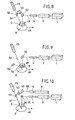
- FIGS. 16a to 16c The corresponding reflected intensity distributions are shown in FIGS. 16a to 16c.
- the ideal course of the intensity distribution is shown in dashed lines in FIG. 16a, the actual course with the full line 64a. This is similar in FIG. 16b, where a deviation of curve 64b from the ideal state is shown. 17c shows the ideal state, which means that the actual course of the intensity distribution 64c is identical to the ideal course.
- the metallized grid 62 serves as a reference structure in the device according to the invention.
- the distance between two grid strips is, for example, 7 pm and their width is 5 pm (FIG. 15).
- the writing laser device 1 is, for example, an argon ion laser of 1 to 5 mW power at a wavelength of 458 nm (for example Spectra Physics, Mountain View, California, Mod. 162A.07; American Laser Corp., Salt Lake City, Utah, Mod. 60C), or a He-Cd laser from 7 to 40 mW Lei power at 442 nm, or 1 to 10 mW at 325 nm (e.g. Liconix, Sunnyvale, California, Mod. 4200 N or Mod. 4200 NB).
- the switching of the continuous laser power is also carried out with an electro-optical modulator beam switch 3 (e.g. Coherent Inc., Palo Alto, California, Modulator Div. Mod. 3010) or an acousto-optical modulator beam switch (e.g. Coherent Modulator Div. Mod. 304D).
- the required switching time results from the writing speed and the local resolution and is e.g. 2 us.
- the subsequent beam expander 4 increases the beam diameter e.g. ten times.
- the horizontal writing beam 49 is deflected in the vertical direction with the deflecting mirror 50.
- the objective 19 has a focal length of 18 mm and a diameter of 10 mm.
- the resulting spot size is about 2 ⁇ m and the depth of field is about 13 ⁇ m.
- the deflecting mirror 50 can be arranged to be controllable or adjustable.
- the scanning laser device 9 is a He-Ne laser with a power of 1 mW and a beam diameter of 0.65 mm. This is enlarged 4-fold with an expander 10 and superimposed on the writing laser beam 49 with an adjustable deflecting mirror 50.
- FIG. 8 shows separate scanning and writing laser beams 49, 55, which are, however, brought onto the same axis with the help of of dichroic mirror 56.
- This mirror has the advantage that it has 100% transmission for one wavelength and 100% reflection for another wavelength.
- This solution also makes it possible to focus both laser beams 49, 55 with the same objective.
- the variants according to FIGS. 11 to 13 are particularly suitable for workpieces with a high relief.
Abstract
Zur Positionsbestimmung und zur Korrektur von mechanischen Bewegungen beim Schreiben von Linien mit einem Schreiblaserstrahl (7) und einem Tastlaserstrahl (9') in einem metallisierten, dreidimensionalen, integrierten Schaltkreis werden beide Strahlen (7, 9') auf dieselbe Achse gebracht und mit Hilfe eines einzigen Tastlaserstrahlteilers (18) sowohl in den Objektivkopf (D) und auf das Werkstück (G) als auch in einen Revolverkopf (G) geführt, der wechselweise mehrere Mess- oder Beobachtungsgeräte einsetzen kann. Einzelne Teile sind gut einstellbar und bei der automatischen Auswertung der festgestellten Werte kann daraus direkt und mit der gewünschten Geschwindigkeit die Korrektur eines eventuellen Fehlers erreicht werden. Für das Ordnen und für das Verkürzen der Strahlenwege wird ein Laserstrahlensammler (C) eingesetzt, der zweckmässig auch mit einem Schreiblaserstrahldetektor (15) versehen ist. Ein weiterer Detektor (18') kann hinter dem Tastlaserstrahlteiler (18) angeordnet sein. Die optische Verbindung zwischen dem Objektivkopf (D) und dem Revolverkopf (E) ist sehr einfach, was eventuelle Fehler durch Vibrationen verhindert. Das erfindungsgemässe Verfahren und die dazugehörige Vorrichtung ist insbesondere für schnelles und präzises Bearbeiten von metallisierten, dreidimensionalen, integrierten Schaltkreisen (Wafer) geeignet.To determine the position and to correct mechanical movements when writing lines with a writing laser beam (7) and a scanning laser beam (9 ') in a metallized, three-dimensional, integrated circuit, both beams (7, 9') are brought onto the same axis and with the aid of a single scanning laser beam splitter (18) both in the lens head (D) and on the workpiece (G) and in a turret head (G) which can alternately use several measuring or observation devices. Individual parts can be easily adjusted and the automatic evaluation of the determined values can be used to correct any errors directly and at the desired speed. A laser beam collector (C) is used for arranging and shortening the beam paths, which is expediently also provided with a writing laser beam detector (15). Another detector (18 ') can be arranged behind the scanning laser beam splitter (18). The optical connection between the lens head (D) and the turret head (E) is very simple, which prevents possible errors due to vibrations. The method according to the invention and the associated device are particularly suitable for fast and precise processing of metallized, three-dimensional, integrated circuits (wafers).
Description
Die vorliegende Erfindung betrifft ein Verfahren und eine Vorrichtung zum Feststellen von Referenzdaten zur Positionsbestimmung und zur Korrektur von mechanischen Bewegungen beim Schreiben von Linien mit einem Schreiblaserstrahl in einem Werkstück mit einem metallisierten, dreidimensionalen, integrierten Schaltkreis. Die vorgenannte Vorrichtung wird kurz als "Laser-Pattern-Generator" bezeichnet.The present invention relates to a method and a device for determining reference data for determining the position and for correcting mechanical movements when writing lines with a writing laser beam in a workpiece with a metallized, three-dimensional, integrated circuit. The aforementioned device is briefly referred to as a "laser pattern generator".
Eine Lösung dieser Art ist aus der europäischen Patentanmeldung Veröffentlichungs-Nr. 0 128 993 bekannt. In dieser Patentanmeldung ist ein Verfahren und eine Vorrichtung beschrieben, bei welchen zusätzlich zum Schreiblaserstrahl auch ein Tastlaserstrahl verwendet wird. Bei der Bearbeitung des Werkstückes mit dem Schreiblaserstrahl tastet der Tastlaserstrahl die Oberfläche des Werkstückes ab. Diese Tastlaserstrahlung wird von der Oberfläche des Werkstückes reflektiert und in einem Strahlendetektor, z.B. in einer Differentialfotodiode, empfangen und ausgewertet. Die ausgewerteten Messungen werden dann für die automatische Erfassung oder Requlation der relativen Bewegung des Werkstückes in bezug auf den Schreiblaserstrahl verwendet.A solution of this kind can be found in European patent application publication no. 0 128 993 known. This patent application describes a method and a device in which a scanning laser beam is also used in addition to the writing laser beam. When processing the workpiece with the writing laser beam, the scanning laser beam scans the surface of the workpiece. This scanning laser radiation is reflected from the surface of the workpiece and in a radiation detector, e.g. in a differential photodiode, received and evaluated. The evaluated measurements are then used for the automatic detection or simulation of the relative movement of the workpiece with respect to the writing laser beam.
In der europäischen Patentanmeldung (Veröffentlichungs-Nr. 0 088 045) ist ein Verfahren zur Herstellung elektrisch leitender Bereiche in integrierten monolythischen Halbleiteranordnungen sowie danach hergestellte Halbleiteranordnung hoher Packungsdichte beschrieben.The European patent application (publication no. 0 088 045) describes a method for producing electrically conductive regions in integrated monolithic semiconductor arrangements and a semiconductor arrangement of high packing density produced thereafter.
Bei der Herstellung kundenspezifischer integrierter Schaltungen werden handelsübliche Siliziumscheiben mit P- und N-resp. N- und P- Strukturen verwendet, auf welchen je nach Verwendungszweck spezifische Kontaktflächen zur Verbindung dieser Strukturen erzeugt werden müssen. Im Gegensatz zu bekannten Technologien werden auf einer Siliziumscheibe galvanisch leitende Bereiche mit standardisierten Aussparungen, welche nach einem vorbestimmten Raster angeordnet sind, beispielsweise durch eine Ätz- oder Auftragungstechnik erzeugt. Je nach der zu erzielenden Schaltungskonfiguration wird nun zwischen diesen Aussparungen die leitfähige Schicht aus Aluminium mittels eines Elektronen- oder elektromagnetischen Strahls direkt oder indirekt entfernt. Besonders geeignet ist hierfür ein Laserstrahl, welcher auf einfache Weise positioniert und gesteuert werden kann und zur Belichtung einer photosensitiven Schicht dient. Dazu werden die Siliziumscheiben relativ zum Laserstrahl kontinuierlich bewegt entlang dem vorbestimmten Raster und die Laserleistung wird mit einem Modulator ein- und ausgeschaltet entsprechend der gewünschten Abtragungsgeometrie. Der Rasterabstand ist in der Grössenordnung von 1-7 pm, die Breite der abgetragenen Linien ist 0.4-2 pm und die Bearbeitungsgeschwindigkeit ist in der Grössenordnung von 1-2 Stunden pro 4" Siliziumscheibe. Daraus ergibt sich eine Bewegungsgeschwindigkeit von 30-100 cm/s und eine Positionstoleranz von 0.3-2.5 pm bei einer Verschiebelänge von 4". Diese Werte der Positionstoleranz können mit mechanischen Verschiebeeinheiten nicht erreicht werden. Die Herstellung der insularen leitenden Bereiche erfolgt anschliessend durch eine Photo-Ätztechnik. Durch dieses Verfahren kann auf teure anwendungsspezifische Photomasken verzichtet werden. Eine entsprechend hergestellte Halbleiteranordnung weist auf ihrer leitenden Schicht die nach dem vorgegebenen Raster angeordneten Aussparungen auf, die End- und/oder Eckpunkte insularer leitender Bereiche darstellen.In the manufacture of customer-specific integrated circuits, commercially available silicon wafers with P and N resp. N and P structures are used, on which, depending on the intended use, specific contact surfaces have to be created to connect these structures. In contrast to known technologies, galvanically conductive areas with standardized cutouts, which are arranged according to a predetermined grid, are produced on a silicon wafer, for example by an etching or application technique. Depending on the circuit configuration to be achieved, the conductive layer made of aluminum is then removed directly or indirectly between these cutouts by means of an electron or electromagnetic beam. A laser beam is particularly suitable for this purpose, which can be easily positioned and controlled and is used to expose a photosensitive layer. For this purpose, the silicon wafers are continuously moved relative to the laser beam along the predetermined grid and the laser power is switched on and off with a modulator according to the desired ablation geometry. The grid spacing is on the order of 1-7 pm, the width of the lines removed is 0.4-2 pm and the processing speed is on the order of 1-2 hours per 4 "silicon wafer. This results in a movement speed of 30-100 cm / s and a position tolerance of 0.3-2.5 pm with a displacement length of 4 ". These values of the position tolerance cannot be achieved with mechanical displacement units. The insular conductive areas are then produced using a photo-etching technique. With this method, expensive application-specific photomasks can be dispensed with. A correspondingly manufactured semiconductor arrangement has on its conductive layer the cutouts arranged according to the predetermined grid, which represent end and / or corner points of insular conductive regions.
Die Aufgabe der vorliegenden Erfindung ist, ein Verfahren und eine Vorrichtung der eingangs genannten Art zu schaffen, die eine präzise gegenseitige Führung des Schreiblaserstrahls in bezug auf das Werkstück auch bei dreidimensionalen Strukturen sichert und sowohl eine Positionsbestimmung bzw. Synchronisation, wie auch eine Positionskorrektur, bzw. Korrektur der mechanisch nicht linearen Bewegung ermöglicht.The object of the present invention is to provide a method and a device of the type mentioned at the outset which precisely guide the writing laser beam with respect to the workpiece, even with three-dimensional structures, and enables both position determination or synchronization, as well as position correction or correction of the mechanically non-linear movement.
Dieses Verfahren und diese Vorrichtung sollen die Erstellung von z.B. 2 pm breiten Trennflächen, d.h. von sogenannten Linien, mit einer Geschwindigkeit von über 300 mm/s ermöglichen.This method and device are intended to create e.g. 2 pm wide dividing surfaces, i.e. of so-called lines with a speed of over 300 mm / s.
Die vorgenannte Aufgabe wird dadurch gelöst, dass der metallisierte Raster des Werkstückes während der linienartigen Arbeitsbewegungen mit dem mittels eines Modulators modulierten d.h. abgeschwächten oder nicht abgeschwächten Schreiblaserstrahl oder einem auf dieselbe Achse gebrachten Tastlaserstrahl abgetastet wird, dass der reflektierte Laserstrahl in wenigstens einem Strahlendetektor empfangen und danach ausgewertet wird, wobei die ausgewerteten Signale zur Positionsbestimmung und zur Korrektur der Relativbewegung des Werkstückes und des Schreiblaserstrahls verwendet werden.The aforementioned object is achieved in that the metallized grid of the workpiece during the line-like working movements with the modulated i.e. by means of a modulator. attenuated or non-attenuated writing laser beam or a scanning laser beam brought on the same axis is scanned such that the reflected laser beam is received in at least one radiation detector and then evaluated, the evaluated signals being used to determine the position and to correct the relative movement of the workpiece and the writing laser beam.
Der Vorteil der Erfindung ist darin zu sehen, dass das vorgenannte Verfahren eine präzise Führung der gegenseitigen Lage des Werkstückes und des Schreiblaserstrahls ermöglicht und zwar auch in dreidimensionalen Strukturen, bei welchen das Streulicht entsteht und das Feststellen der Referenzdaten verfälschen könnte, wobei der Schreiblaserstrahl sowohl beim Schreiben wie im eventuell abgeschwächten Zustand zum Abtasten verwendet werden kann.The advantage of the invention can be seen in the fact that the aforementioned method enables precise guidance of the mutual position of the workpiece and the writing laser beam, even in three-dimensional structures in which the scattered light occurs and could falsify the detection of the reference data, the writing laser beam being used both in the case of Write as can be used for scanning in the possibly weakened state.
Nach einer Weiterausbildung gemäss dem Anspruch 2 werden der oder die Laserstrahlen senkrecht oder mit einer Abweichung bis + 10° auf die bearbeitete Fläche des integrierten Schaltkreises des Werkstückes gesendet. In dem angegebenen Toleranzbereich arbeitet der Schreiblaserstrahl bzw. der Abtastlaserstrahl ausreichend zuverlässig.According to a further training according to claim 2, the laser beam or beams are sent vertically or with a deviation of up to + 10 ° on the machined surface of the integrated circuit of the workpiece. In the specified tolerance range, the writing laser beam or the scanning laser beam operates with sufficient reliability.
Gemäss dem Anspruch 3 wird die Korrektur der von der Linie abweichenden Bewegung des Werkstücks mit einem steuerbaren Strahlablenker, z.B. mit steuerbarem Umlenkspiegel vor dem Objektiv und/oder mit steuerbarer schräggestellter Planplatte nach dem Objektiv und/oder mit steuerbarer Verschiebung des Objektives durchgeführt. Durch die genannten verschiedenen Verfahrensschritte erreicht man mit einfachen Mitteln die gewünschte Korrektur.According to
Gemäss dem Anspruch 4 ist es zweckmässig, wenn ein Modulationssignal des Schreiblaserstrahls den Verstärkungsfaktor eines Signalverstärkers direkt steuert, so dass auch bei unterschiedlicher Strahlleistung gleiche Ausgangssignale erreicht werden.According to
Nach einer Weiterentwicklung gemäss Anspruch 5 fällt der polarisierte Schreiblaserstrahl durch einen polarisierenden Strahlteiler als Analysator des elektrooptischen Modulators-Strahlschalters auf die bearbeitete Fläche des Werkstücks und der Strahlendetektor erhält in beiden Zuständen des Modulators - Strahlschalters dieselbe Leistung.According to a further development according to claim 5, the polarized write laser beam falls through a polarizing beam splitter as an analyzer of the electro-optical modulator beam switch onto the machined surface of the workpiece and the beam detector receives the same power in both states of the modulator beam switch.
Gemäss der vorteilhaften Lösung nach Anspruch 6 wird zusätzlich zum Schreiblaserstrahl ein Tastlaserstrahl verwendet, welcher mit einem dichroitischen Strahlteiler auf dieselbe Achse gebracht wird und denselben Strahlengang durchläuft wie der Schreiblaserstrahl, somit werden für die Wellenlänge des Schreiblaserstrahls ungünstige Oberflächenzustände der integrierten Schaltung des Werkstückes ausgeglichen und die Wellenlänge des Tastlaserstrahls wird von derjenigen des Schreiblaserstrahls unterschiedlich gewählt. Diese Lösung ist in dem Fall notwendig, wenn man zwei wesentlich verschiedene Wellenlängen in bezug auf die Oberfläche des bearbeiteten Werkstückes benötigt.According to the advantageous solution according to
Es ist vorteilhaft, wenn gemäss dem Anspruch 7 neben dem Signal des reflektierten Laserstrahls das diffusgestreute Licht mit einem zusätzlichen Detektor gemessen und das Verhältnis der beiden Signale gebildet wird und dadurch die unterschiedliche lokale Oberflächenbeschaffenheit der integrierten Schaltungen des Werkstückes, wie Reflektions- und Streuverhalten der metallisierten Oberfläche und der darunter liegenden Materialien, kompensiert werden. Mit Hilfe dieses Verfahren werden eventuelle Fehler verhindert, die infolge von verschiedenen Materialien oder verschiedener Bearbeitung der Oberfläche der Materialien entstehen könnten.It is advantageous if, in addition to the signal of the reflected laser beam, the diffuse scattered Light is measured with an additional detector and the ratio of the two signals is formed, thereby compensating for the different local surface properties of the integrated circuits of the workpiece, such as the reflection and scattering behavior of the metallized surface and the underlying materials. With the help of this method, possible errors that could arise as a result of different materials or different processing of the surface of the materials are prevented.
Besonders vorteilhaft ist es, wenn gemäss Anspruch 8 der Schreiblaserstrahl (Blaustrahl) und der Tastlaserstrahl (Rotstrahl) in einem Laserstrahlensammler mit einem Schreiblaserstrahlteiler und einem Tastlaserstrahlspiegel in einen Objektivkopf reflektiert werden und wenn ein Teil des Schreiblaserstrahls mit dem Schreiblaserstrahlteiler in einen Schreiblaserstrahldetektor abgezweigt wird. Der Vorteil dieser Weiterentwicklung besteht darin, dass im Laserstrahlensammler beide Laserstrahlen präzis ausgerichtet werden können, was zusätzlich beim Schreiblaserstrahl durch den zuständigen Schreiblaserstrahldetektor kontrolliert und bzw. gesteuert wird. Es ist zweckmässig, wenn der metallisierte, dreidimensionale, integrierte Schaltkreis mit einer Fotolackschicht bedeckt ist, die vom Schreiblaser belichtet wird.It is particularly advantageous if, according to
Gemäss einer Weiterbildung nach Anspruch 9 werden der Schreiblaserstrahl und der Tastlaserstrahl im Laserstrahlensammler auf derselben Achse auf einen Tastlaserstrahlteiler des Objektivkopfes geführt, von dem der Tastlasertrahl und der Schreiblaserstrahl durch das Objektiv auf das Werkstück geführt werden. Ein Teil des reflektierten Tastlaserstrahls wird durch den Tastlaserstrahlteiler in einen Revolverkopf reflektiert. Der Vorteil ist darin zu sehen, dass die gemeinsame Führung des Schreiblaserstrahls und des Tastlaserstrahls die Präzision der Funktion weiter erhöht, weil man wenigstens in einem bestimmten Teil des Strahlenganges für beide Laserstrahlen dieselben optischen Bestandteile verwenden kann.According to a development according to
Gemäss Anspruch 10 ist es zweckmässig, wenn die in Detektoren und/oder aus dem Objektivkopf und/oder aus dem Revolverkopf festgestellten Laserlicht-Signale ausgewertet werden und die Funktionslage somit erfasst oder erreicht wird. Dieses Verfahren kann mit an sich bekannten elektronischen Mitteln automatisch mit ausreichender Genauigkeit arbeiten.According to
Die Vorrichtung zur Durchführung des Verfahrens nach Anspruch 1 enthält gemäss Anspruch 11 ein Schreiblasergerät mit nachgeschaltetem Modulator, einen Aufweiter und ein Objektiv und für die Auswertung ist ein Strahlteiler des reflektierten Lichtes einem Detektor zugeordnet.The device for carrying out the method according to
Gemäss einer Weiterentwicklung ist nach Anspruch 12 der Strahlteiler ein polarisierender Strahlteiler, welcher als Analysator des elektrooptischen Modulators vorgesehen ist.According to a further development, the beam splitter is a polarizing beam splitter which is provided as an analyzer of the electro-optical modulator.
Eine vorteilhafte Ausführungsform der Vorrichtung gemäss Anspruch 13 besteht darin, dass die Laserschreibvorrichtung zusätzlich ein Tastlasergerät mit einer vom Schreiblasergerät unterschiedlichen Wellenlänge enthält und dass die Vorrichtung mit einem dichroitischen Strahlteiler zum Überlagern des Tastlaserstrahls auf die Achse des Schreiblaserstrahls und zum nachträglichen Separieren des Tastlaserstrahls auf einen Detektor versehen ist. Die Verwendung des dichroitischen Strahlteilers ermöglicht eine einfache Auswertung bei Verwendung von zwei Lasern mit verschiedenen Wellenlängen.An advantageous embodiment of the device according to
Nach einer vorteilhaften Variante gemäss Anspruch 14 enthält eine Steuervorrichtung zum Erreichen der richtigen gegenseitigen Lage des integrierten Schaltkreises und der Laserstrahlung einen Regelkreis, welcher aus einem Operationsverstärker mit nachgeschaltetem Hochspannungsverstärker und mindestens einem Piezoelement besteht. Das wenigstens eine Piezoelement ist zur mechanischen sehr feinen und schnellen Steuerung der beweglichen Teile insbesondere geeignet.According to an advantageous variant according to
Nach einer vorteilhaften Weiterentwicklung gemäss Anspruch 15 bildet der Objektivkopf mit dem Revolverkopf ein gemeinsames Optikmodul, dessen Verbindungsgteil nur der Tastlaserstrahlteiler ist. Diese Lösung ist besonders zweckmässig, weil zwischen dem Objektivkopf und dem Revolverkopf kein Umlenkspiegel steht, der die Abtastfläche des Detektors und damit dessen Geschwindigkeit beeinflusst.According to an advantageous further development according to
Es ist vorteilhaft, wenn nach Anspruch 16 der Laserstrahlensammler mit einem Schreiblaserstrahldetektor versehen ist. Diese Konstruktion ermöglicht, die Richtung und eventuell auch die Breite des Schreiblaserstrahls gleich hinter der Schreiblaserstrahlquelle zu korrigieren und eventuelle Ungenauigkeiten zu erfassen.It is advantageous if, according to
Nach einer bevorzugten Ausführungsform gemäss Anspruch 17 ist der Revolverkopf mit wenigstens zwei der drei Einheiten: Tastlaserstrahldetektor, Scherungs-Interferometer-Okular und Mikroskopokular mit Fadenkreuz, versehen. Durch diese Anordnung werden in der unmittelbaren Nähe des Objektivkopfes wenigstens zwei für die Kontrolle der Funktionsweise der Vorrichtung zweckmässige Apparate angeordnet. Die Verbindung dieser Funktionsteile mit dem Revolverkopf ist sehr platzsparend und ermöglicht die beliebige Wahl einer bestimmten optischen Einheit des Objektivkopfes.According to a preferred embodiment according to
Nach einer Weiterbildung gemäss Anspruch 18 ist die Schreiblaserstrahlquelle und/oder die Tastlaserstrahlquelle mit je wenigstens einer Lochblende innerhalb des Aufweiters versehen. Diese Massnahme sichert ausreichend bildinformationsfreie Laserstrahlen, wie sie bei den neuartigen Verfahren zweckmässig sind. Die Lochblende wird auch als "pinhole" bezeichnet.According to a development according to
Nach Anspruch 19 ist zweckmässigerweise das Mikroskopokular des Objektivkopfes mit einem Schreiblasersperrfilter versehen. Diese Lösung verhindert, dass das menschliche Auge mit einer zu hohen Strahlungsleistung eventuell beschädigt wird.According to
Nach einer Weiterbildung nach Anspruch 20 ist in Richtung der auf derselben Achse geführten Schreib- und Tastlaserstrahlen hinter dem Tastlaserstrahlteiler ein Detektor angeordnet. Dieser weitere Detektor kann die Richtung des gemeinsamen Strahlenganges der Tast- und Schreiblaserstrahlen kontrollieren.According to a development according to
Besonders vorteilhaft ist es, wenn nach Anspruch 21 wenigstens ein Detektor aus mehreren Feldern besteht. Diese Lösung signalisiert nicht nur eine eventuelle Abweichung von der gewünschten Richtung sondern auch die Richtung, in welcher diese Abweichung stattfindet. Dies erleichtert die Auswertung einer eventuellen Abweichung und deren automatische Korrektur.It is particularly advantageous if at least one detector consists of several fields. This solution not only signals a possible deviation from the desired direction but also the direction in which this deviation takes place. This facilitates the evaluation of a possible deviation and its automatic correction.
Die Erfindung wird anhand mehrerer Zeichnungen näher erläutert.The invention is explained in more detail with reference to several drawings.
Es zeigt:
- Fig. 1 eine schematische Anordnung der besonders vorteilhaften erfindungsgemässen beispielsweisen Ausführungsform, wobei die Fig. 1a im linken Teil in Draufsicht und die Fig. 1b im rechten Teil in Vorderansicht gezeichnet sind,
- Fig. 2 eine Vorderansicht auf den Laserstrahlensammler aus der Figur 1a,
- Fig. 3 eine Draufsicht auf den Laserstrahlensammler gemäss Fig. 2,
- Fig. 4 ein Optikmodul, bestehend aus einem Objektivkopf und einem Revolverkopf, in teilweisem Schnitt,
- Fig. 5 den Schnitt V-V aus der Fig. 4,
- Fig. 6 eine Draufsicht auf den Revolverkopf aus der Fig. 4,
- Fig. 7 eine beispielsweise Ausführungsform eines Detektors mit mehreren Feldern,
- Fig. 8 eine andere beispielsweise erfindungsgemässe Lösung, bei der das Abtasten und das Schreiben mit demselben Laserstrahl durchgeführt wird,
- Fig. 9 eine Ausführungsform mit polarisiertem Schreiblaserstrahl und einem polarisierenden Strahlteiler,
- Fig. 10 eine beispielsweise Ausführungsform mit zwei Lasern mit verschiedenen Wellenlängen,
- Fig. 11 eine beispielsweise Lösung, bei der der Tastlaserstrahl senkrecht auf das Werkstück fällt und zwei Strahlteiler vorgesehen sind,
- Fig. 12 eine Variante der Lösung gemäss der Fig. 11, bei der ein polarisierender Strahlteiler verwendet wird,
- Fig. 13 eine andere Variante, in der ein dichroitischer Strahlteiler für zwei verschiedene Laserstrahlen Verwendung findet,
- Fiq. 14 einen schematischen Schnitt durch den Optikkopf, wobei sowohl der reflektierte Laserstrahl als auch das diffuse Licht ausgewertet werden,
- Fig. 15 ein Werkstück mit metallisiertem Raster und beispielsweise angeordneten Laserflecken und
- Fiq. 16a bis 16c drei Intensitätverteilungen, die der Lage der Laserflecke in der Fig. 15 entsprechen.
- 1 shows a schematic arrangement of the particularly advantageous exemplary embodiment according to the invention, the FIG. 1a in the left part being drawn in plan view and FIG. 1b in the right part being drawn in front view,
- 2 shows a front view of the laser beam collector from FIG. 1a,
- 3 shows a top view of the laser beam collector according to FIG. 2,
- 4 an optical module consisting of an objective head and a turret head, in partial section,
- 5 shows the section VV from FIG. 4,
- 6 is a plan view of the turret from FIG. 4,
- 7 shows an exemplary embodiment of a detector with several fields,
- 8 shows another solution according to the invention, for example, in which the scanning and writing are carried out with the same laser beam,
- 9 shows an embodiment with a polarized write laser beam and a polarizing beam splitter,
- 10 shows an example embodiment with two lasers with different wavelengths,
- 11 shows an example of a solution in which the scanning laser beam falls perpendicularly onto the workpiece and two beam splitters are provided,
- 12 shows a variant of the solution according to FIG. 11, in which a polarizing beam splitter is used,
- 13 shows another variant in which a dichroic beam splitter is used for two different laser beams,
- Fiq. 14 shows a schematic section through the optical head, both the reflected laser beam and the diffuse light being evaluated,
- 15 shows a workpiece with a metallized grid and, for example, arranged laser spots and
- Fiq. 16a to 16c three intensity distributions which correspond to the position of the laser spots in FIG. 15.
Gemäss Fig. 1a sind die Schreiblaserstrahlquelle A und die Tastlaserstrahlquelle B parallel mit optischen Achsen in horizontaler Lage angeordnet. Die Schreiblaserstrahlquelle A enthält ein Schreiblasergerät 1, hinter welchem sich ein Laserstrahlschalter 2 zum Ausschalten des Schreiblaserstrahls 7 bei offenem Gerät befindet. Eine Lochblende 2' ist in einem Aufweiter 4 des Schreiblasergeräts 1 angeordnet. Zwischen diesen Bestandteilen befindet sich in der optischen Achse ein Modulator 3. Linsen des Aufweiters 4 sind mit der Ziffer 4' bezeichnet und die ganze Schreiblaserstrahlquelle A ist in einem Gehäuse 5 gelagert. Der Modulator 3 und der Aufweiter 4 sind mit einstellbaren Befestigungselementen 6 im genannten Gehäuse 5 gehalten. Das ganze Gehäuse 5 ist ebenfalls mit einstellbaren Befestigungselementen 6 versehen, die ermöglichen, die optische Achse dieser Schreiblaserstrahlquelle A richtig zu ordnen. Der Schreiblaserstrahl ist mit Bezugsziffer 7 bezeichnet. Die Tastlaserstrahlquelle B ist in einem Gehäuse 8 gelagert. Sie enthält ein Tastlasergerät 9, aus welchem ein Tastlaserstrahl 9' in den Aufweiter 10 der Tastlaserstrahlquelle B geleitet ist. Auch dieser Aufweiter 10 enthält zusätzlich zu den schon erwähnten Linsen 4' eine Lochblende 11. Die Tastlaserstrahlquelle B enthält auch weitere Elemente, die schon bei der Beschreibung der Schreiblaserstrahlquelle A erwähnt wurden.1a, the writing laser beam source A and the scanning laser beam source B are arranged in parallel with optical axes in a horizontal position. The writing laser beam source A contains a writing
Gleiche Teile sind in allen Zeichnungen mit denselben Bezugsziffern versehen.Identical parts are provided with the same reference numbers in all drawings.
Aus dem Tastlasergerät 9 wird ein Tastlaserstrahl 9' in den Aufweiter 10 geführt. Die Bestandteile der Tastlaserstrahlquelle sind in einem Gehäuse 8 gelagert, das gleich wie das Gehäuse 5 der Schreiblaserstrahlquelle A mit einstellbaren Befestigungslementen 6 in die richtige Position gebracht werden kann. In der Richtung der optischen Achsen des Schreiblaserstrahls 7 und des Tastlaserstrahls 9' befindet sich ein Laserstrahlensammler C. Dieser enthält in einem Gehäuse 12 einen Schreiblaserstrahlteiler 13 und einen Tastlaserstrahlspiegel 14, die in der Fig. 1a in Draufsicht dargestellt sind. Diese Elemente sind einstellbar mittels Einstellelementen 16 im genannten Gehäuse 12 gelagert. Links vom Schreiblaserstrahlteiler 13 befindet sich ein Schreiblaserstrahldetektor 15, der die richtige Ausgangslage des Schreiblaserstrahls 7 kontrolliert. Der reflektierte Schreiblaserstrahl 7 und der reflektierte Tastlaserstrahl 91 verbinden sich auf einer derselben Achse 17, die dann direkt in die Fig. 1b führt. Diese Fig. 1b weist eine vertikale optische Achse auf. Der gemeinsame Strahlengang 17 fällt zuerst auf einen Tastlaserstrahlteiler 18. Von diesem geht der überwiegende Teil der Strahlung in das Objektiv 19 des Objektivkopfes D und weiter auf das Werkstück D. In der Richtung der auf derselben Achse geführten Schreib- und Tastlaserstrahlen 17 befindet sich hinter dem Tastlaserstrahlteiler 18 ein Detektor 18'. Die Aufgabe dieses Detektors 18' ist, den richtigen Strahlengang 17 zu überwachen. Das Objektiv 19 weist Einstellelemente 20 auf, wobei einige von ihnen mit einem piezoelektrischen Antrieb 21 versehen sind. Direkt oberhalb des Objektivkopfes D ist ein Revolverkopf E drehbar angeordnet, wobei dieser Objektivkopf D und der Revolverkopf E eine funktionelle Einheit, ein Optikmodul F bilden. Der Objektivkopf E enthält im wesentlichen einen Revolverhalter 22, auf dem sich drehbar in diesem Beispiel ein Tastlaserstrahldetektor 23, ein Scherungs-Interferometer-Okular 24 (shearing-interferometer) und ein Mikroskopokular 25 mit Fadenkreuz befinden. Dieses Mikroskopokular 25 ist aus Sicherheitsgründen mit einem Schreiblasersperrfilter 25' versehen.A scanning laser beam 9 'is guided into the
Der Laserstrahlensammler C, der Objektivkopf D und das Optikmodul F, das aus dem Objektivkopf D und dem Revolverkopf E besteht, werden in den nächsten Zeichnungen näher dargestellt und im Text ausführlicher beschrieben. In der Zeichnung 1b ist aus Übersichtlichkeitsgründen der Revolverkopf E in einer entwickelten, also geradlinigen Form gezeichnet. Die richtige kreisförmige Form wird später anhand der Fig. 6 sichtbar.The laser beam collector C, the lens head D and the optics module F, which consists of the lens head D and the turret E, are shown in more detail in the next drawings and described in more detail in the text. In the drawing For reasons of clarity, turret 1b shows the revolver head E in a developed, i.e. linear form. The correct circular shape will be seen later in FIG. 6.
Die Fig. 2 zeigt in Vorderansicht den Laserstrahlensammler C. In einem Halter 26 ist der schon beschriebene Schreiblaserstrahlteiler 13 kardanisch aufgehängt. Auf ähnliche Weise ist in einem Halter 27 der ebenfalls schon erwähnte Tastlaserstrahlspiegel 14 angeordnet. Mehrere Tragelemente 28 des Laserstrahlensammlers C sind zwar für die Funktionsweise des Verfahrens und der Vorrichtung nicht wichtig, es ist jedoch selbstverständlich, dass sie ausreichend massiv hergestellt werden, was übrigens auch Führungsplatten 28' der Halter 26, 27 und einen Verbindungskörper 30 betrifft. Stellschrauben 29 dienen für die Einstellung der Halter 26, 27. Der massive Verbindungskörper 30 verbindet die Tragelemente 28 mit einem Arbeitstisch 31. Mit einem Tragelement 28 ist im linken Teil der Fig. 2 auch der schon erwähnte Schreiblaserstrahldetektor 15 befestigt.2 shows a front view of the laser beam collector C. The write
In der Fig. 3 ist eine Draufsicht auf die konstruktive Ausbildung gemäss der Fig. 2 veranschaulicht. Die Bestandteile wurden schon vorher beschrieben. In der Fig. 3 sind zusätzlich noch die Stellschrauben 29' und Führungsplatten 28' gezeigt. Diese Stellschrauben 29 gemeinsam mit den Stellschrauben 29' ermöglichen die richtige Einstellung der Elemente 13, 14.FIG. 3 illustrates a top view of the construction according to FIG. 2. The components have already been described. In Fig. 3, the set screws 29 'and guide
Gemäss Fig. 4 ist ein teilweiser vertikaler Schnitt durch das Optikmodul F gezeigt, das im unteren Teil aus dem Objektivkopf D und im oberen Teil aus dem Revolverkopf E besteht. Die Bestandteile des Objektivkopfes D werden im wesentlichen mit vier Stangen 32 gehalten, die parallel mit der optischen Achse durch den ganzen Objektivkopf D geführt werden und in Stangenhaltern 33 gelagert sind. Im Unteren Teil des Objektivkopfes D ist die gegenseitige Lage von zwei Stangenhaltern 33 mittels zwei Blattfedern 34 fixiert. Der Tastlaserstrahlteiler 18 ist in einem Halter 35 gelagert.4 shows a partial vertical section through the optics module F, which consists of the objective head D in the lower part and the turret head E in the upper part. The components of the lens head D are essentially held by four
Auf diesen Tastlaserstrahlteiler 18 kommen von links die auf derselben Achse geführten Schreib- und Tastlaserstrahlen, die in diesen gemeinsamen Strahlengang mit der Bezugsziffer 17 bezeichnet sind. Zur Halterung des Objektivs 19 dient unter anderem auch ein Objektivhaltering 36. Es ist selbstverständlich, dass die Bestandteile des Objektivkopfes D entlang der vier Stangen 32 verschoben werden können und so die optimale gegenseitige Lage der optischen Teile eingestellt werden kann. Dies betrifft selbstverständlich nur die Lage der Teile in der Richtung der optischen Achse. Für Bewegungen senkrecht zu der optischen Achse ist der piezoelektrische Antrieb 21 vorgesehen. Die Stangenhalter 33 und andere Befestigungselemente werden mit Schrauben 37 zusammengehalten, von welchen nur einige eingezeichnet sind, weil sie die Erfindungsidee nicht betreffen und Schraubenverbindungen selbstverständlich an sich bekannt sind. Mit dem oberen Teil des Objektivkopfes D ist ein Revolverkopfdrehtisch 38 drehbar verbunden. Für die ausreichend feste aber drehbare Fixierung dieses Revolverkopfdrehtisches 38 dient ein Revolverhalter 22, der mit einer Befestigungsschraube 44 in einem Träger 43 befestigt ist. Im Revolverkopf E sind in diesem Beispiel drei selbständige Elemente gelagert. Vor allem sollte man ein Prisma 40 erwähnen, mit welchem man die horizontale optische Achse in die vertikale Richtung bringen kann. Der Scherungs-Interferometer enthält ein Okular 24 mit einer Mattscheibe und eine Planplatte 39. Der Revolverkopf E enthält weiter das Mikroskopokular 25 mit einem Fadenkreuz und den Tastlaserstrahldetektor 23. Diese Bestandteile sind auf einem Revolverkopfdrehtisch 38 angeordnet, der in diesem Fall drei Bohrungen 42 aufweist. Diese Bohrungen 42 und eine anschaulichere Darstellung des Revolverkopfes E sind aus der folgenden Fig. 6 gut ersichtlich. In der vertikalen optischen Axe ist unter dem Prisma 40 ein Schreiblasersperrfilter 25' und eine Tubuslinse 41 gelagert.The scanning and scanning laser beams, which are guided on the same axis and which are designated in this common beam path with the
Die Fig. 5 zeigt den Schnitt V-V aus der Fig. 4. Es handelt sich also um den Schnitt durch den Objektivkopf D, wo auch die Befestigung dieses Objektivkopfes D gut sichtbar ist. Im oberen Teil der Fig. 5 ist der mehrteilige Träger 43 gezeigt, der eine dicke Platte enthält und zur Aufnahme der Befestigungsschraube 44 des Revolverkopfes E dient.5 shows the section V-V from FIG. 4. It is therefore the section through the lens head D, where the attachment of this lens head D is also clearly visible. In the upper part of FIG. 5, the
In der Fig. 6 ist eine vereinfachte Draufsicht auf den Revolverkopf E dargestellt. Diese Zeichnung veranschaulicht den Tastlaserstrahldetektor.23 mit einem Arretierstift 46 sowie das Scherungs-Interferometer-Okular 24 mit einer Planplatte 39 und das Mikroskopokular 25. Alle diese drei Teile sind mit einem Halter 45 drehbar befestigt, so dass man beliebig den gewünschten Apparat in die optische Achse des Objektivkopfes D bringen kann. In dieser Zeichnung ist auch der Träger 43 sichtbar, auf dem der Revolverkopf E befestigt ist.6 shows a simplified top view of the turret E. This drawing illustrates the scanning
Die Fig. 7 zeigt vereinfacht ein Beispiel eines Detektors, in diesem Fall des Tastlaserstrahldetektors 23, der aus mehreren Feldern 47 zusammengesetzt ist. Bei einer richtigen Funktion wird das mittlere Feld bestrahlt, bei einer Abweichung von dieser gewünschten Lage werden ein oder mehrere Nebenfelder erfasst. Weil diese Felder 47 einzeln ausgewertet werden können, gibt dies die Information, in welcher Richtung sich die Abweichung von der richtigen Lage erstreckt.FIG. 7 shows in simplified form an example of a detector, in this case the scanning
In dieser beispielsweisen Ausführungsform wurde als das Schreiblasergerät 1 ein natürlich luftgekühltes Helium-Cadmium Lasersystem (Marke Liconix, Sunnyvale, CA 94086, USA) verwendet. Dieses Lasergerät besteht aus einem stromgeregelten Hochspannungsspeisegerät Liconix, Modell 4200 PS, mit Kalt- und Warmstart, mit Zeitprogramm und Zündsteuerung, sowie aus einem Lasergerät Modell 4110B. Die Hauptmerkmale des Schreiblasergerätes 1 sind folgende: Lichtwellenlänge 442 nm, Lichtleistung ist 10 mW (Dauerlicht), die Intensität ist normal über den Strahldurchmesser verteilt, Polarisations-Richtung ist horizontal +-5%, Strahldurchmesser 1,1 mm.In this exemplary embodiment, a naturally air-cooled helium-cadmium laser system (brand Liconix, Sunnyvale, CA 94086, USA) was used as the writing
Das Tastlasergerät 9 ist ein natürlich luftgekühltes Melles Griot, (ILEE AG, CH-Schlieren) Helium-Neon-Lasersystem, bestehend aus Lasergerät, Modell 05-LHP-111 und Modell 05-LPN-340 Speisegerät (1800 V, 6,5 mA). Die Lichtwellenlänge beträgt 633 nm, Lichtleistung ist 1 mW, Abweichung der Strahlachse nach dem Kaltstart ist < 200 pRad, nach 15 Min. Betrieb 30 uRad. Die Strahl-Divergenz ist < 1,3 mRad, Regelabweichung der Lichtleistung ist < +-5%.The
Der Modulator 3 ist ein natürlich luftgekühltes, elektrisch gesteuertes Coherent-Blaulaserlicht-Unterbrecher-System (Coherent Associates, Danbury, Conn. 06810, USA), bestehend aus dem Steuergerät Modell 31 und dem Modulator Modell 3010. Das Modulator-Rohr enthält einen bruchempfindlichen, in Flüssigkeit mit gleicher Brechungszahl eingebettetem Kaliumdihydrogenphosphat-Kristall mit zwei Steuerelektroden und einem am Ausgang angebauten Fotodioden Lichtmesser. Der Kristall wirkt als Polarisationsfilter, dessen Richtungswinkel mit einer Spannung von ca. 600 V über 90 Grad gedreht werden kann.The
Der Aufweiter 4 besteht aus zwei Sammellinsen und einer Lochblende, die auch "pinhole" genannt wird, mit einem Durchmesser von 10 pm, im gemeinsamen Brennpunkt der Sammellinsen. Der Aufweiter vergrössert den Durchmesser und verkleinert die Divergenz des Laserstrahls im Aufweitungsverhältnis, das ist das Verhältnis der Brennpunktabstände, und überträgt das Bild des Lichtpunktes in der Lochblende im Ausgangsstrahl, d.h. entfernt z.B. wegen Staub entstandene dunkle Punkte des ankommenden Laserstrahls und macht die Richtung des Ausgangsstrahls unabhängig von der Richtung des Eingangsstrahls.The
Als Teiler 13 wird ein dichroitischer Teiler verwendet, der aus einer planparallelen Glasplatte mit einseitig aufgedampfter dielektrischer Metallschicht besteht. Dieser lässt das Licht der bestimmten Wellenlänge, d.h. der einen Farbe, das in der Durchgangsrichtung eintrifft, in der gleichen Richtung durch, versetzt dabei den Strahlungsaustrittspunkt abhängig von der Brechungszahl des Glases für die bestimmte Wellenlänge in Abhängigkeit von der Dicke des Glases.As the
Der an sich bekannte piezoelektrische Antrieb 21 besteht in diesem Beispiel aus Burley, Modell PZ70, 1000 V Speisegerät und einem Burley, Modell PZ40 Piezotranslator. Der Piezokristallstapel dehnt sich in etwa proportional mit der angelegten Spannung aus und verschiebt dadurch das Objektiv 19 in der horizontalen Achse.The
Ein Mikroskop besteht aus dem Objektiv 19 und dem Mikroskopokular 25. Das Objektiv 19 weist ein Sammellinsensystem mit oder ohne Standard-Deckglas auf der Arbeitsseite auf, fokussiert den konzentrisch und parallel eintretenden blauen und roten Laserstrahl zum kleinstmöglichen Brennfleck im Arbeitsabstand, leitet ein vergrössertes Luftbild des konzentrisch zum Brennfleck liegenden grün beleuchteten Bildfeldes ab, das mit dem Mikroskopokular 25 betrachtet werden kann. Es setzt die mechanische Verschiebung durch den piezoelektrischen Antrieb 21 in eine Verschiebung des Bild- und Brennfleck-Mittelpunktes um.A microscope consists of the objective 19 and the
Das Mikroskopokular 25 ist als ein Sammellinsensystem mit der Funktion einer Lupe ausgebildet und leitet aus dem Luftbild des Objektivs 19 ein vergrössertes sichtbares Bild ab.The
Der Scherungs-Interferometer besteht aus einem in den Strahlengang einschiebbaren Spiegel, einer planparallelen Glasplatte 39, und einem Okular 24, bildet ein Scherungs-Interferometer zum Messen der Abweichung des Abstandes der reflektierenden Aluminium-Fläche von der Fokussierebene des Objektivs 19.The shear interferometer consists of a mirror that can be inserted into the beam path, a plane-
Die Detektoren 15, 181 und 23 bestehen zweckmässig aus je einer zentralen, inneren unempfindlicheren und einer äusseren empfindlicheren Anordnung von Silizium-Photodioden. Sie leiten aus dem vom Werkstück reflektierten oder auf eine andere Weise gewonnenen Laserstrahl die Feststellung ab, ob sich der zuständige Laserstrahl in der richtigen Lage befindet oder in einer bestimmten Richtung sich von dieser Lage entfernt.The
Die Figuren 8 bis 13 zeigen in schematischer Darstellung einige mögliche Varianten des Erfindungsgegenstandes.Figures 8 to 13 show a schematic representation of some possible variants of the subject matter of the invention.
Fig. 8 zeigt ein vereinfachtes Funktionsschema der erfindungsgemässen Vorrichtung mit einzigem Lasergerät 1. Ein Werkstück 9 ist aus einer Siliziumplatte hergestellt und mit einem metallischen Raster versehen, der erst in den nächsten Zeichnungen gezeigt wird. Ein Pfeil 48 zeigt die Bewegungsrichtung des Werkstückes G. Mit der Ziffer 49 ist ein Schreiblaserstrahl bezeichnet, der aus einem Schreiblaser 1 durch einen Modulator 3 und einen Aufweiter 4 auf einen Umlenkspiegel 50 fällt. Dieser Schreiblaserstrahl 49 entspricht dem Schreiblaserstrahl 7, ist jedoch wegen der Übersichtlichkeit gestrichelt gezeichnet. Der Schreiblaserstrahl 49 wird dann durch den Objektivkopf D mit einem Objektiv auf das bearbeitete Werkstück G geführt. Das vom Werkstück G reflektierte Licht 51 fällt auf einen Strahlteiler 52. Von diesem wird ein Teil des Lichtes in einen Detektor 53 geleitet und durch den Strahlteiler 52 geht ein Teil des reflektierten Lichtes in ein Mikroskopokular 25.8 shows a simplified functional diagram of the device according to the invention with a
Fig. 9 entspricht im wesentlichen der Fig. 8 mit dem Unterschied, dass in dem Objektiv D ein polarisierender Strahlteiler 54 angeordnet ist, der eine Polarisationsrichtung des reflektierten Lichtes in den Detektor 53 leitet.FIG. 9 essentially corresponds to FIG. 8 with the difference that a
Fig. 10 zeigt eine Lösung, wo zusätzlich noch ein Tastlaserstrahl 55 Verwendung findet. Dieser Tastlaserstrahl 55 entspricht dem Taslasertrahl 9' im ersten Beispiel, ist jedoch wegen der Übersichtlichkeit punktiert gezeichnet, so dass aus den Zeichnungen die Funktion der Laserstrahlen ersichtlich ist. Diese Lösung ist dann zweckmässig, wenn die Beschaffenheit der Oberfläche des Werkstückes G zwei verschiedene Wellenlängen braucht. Der Tastlaserstrahl 55 wird in einem Tastlasergerät 9 erzeugt und weiter durch einen Aufweiter 10 auf einen Umlenkspiegel 50 geführt. Von diesem Umlenkspiegel 50 reflektiert der Tastlaserstrahl 55 durch den dichroitischen Strahlteiler 56 und durch den Objektivkopf D gemeinsam mit dem Schreiblaserstrahl 49 auf die Oberfläche des Werkstückes G. Beide Laserstrahlen gehen auf das Werkstück G in derselben Linie und auch in derselben Linie kontaktieren sie den Strahlteiler 52. Der Tastlaserstrahl 55 wird von diesem Strahlteiler 52 in den Detektor 53 reflektiert. Der reflektierte Schreiblaserstrahl 51 tritt in das Mikroskopokular 25 ein.FIG. 10 shows a solution where a
Gemäss Fig. 11 ist der Strahlteiler 52 vor dem Objektiv D angeordnet und der reflektierte Schreiblaserstrahl 49 wird dann mit Hilfe eines weiteren Strahlteilers 52 in den Detektor 53 und in das Mikroskopokular 25 geleitet.11, the
Bei der Ausführungsform gemäss Fig. 12 wird direkt in den Objektivkopf D ein polarisierender Strahlteiler 54 angeordnet, der eine Polarisationsrichtung des reflektiertes Lichtes 51 in den Strahlendetektor 53 leitet, wobei das Mikroskopokular 25 das reflektierte Licht direkt vom Strahlteiler 52 erhält.In the embodiment according to FIG. 12, a
Gemäss Fig. 13 werden wieder sowohl der Schreiblaserstrahl 49 als auch der Tastlaserstrahl 55 verwendet; sie werden senkrecht zu dem Werkstück G geleitet. In dem gemeinsamen Weg beider Laserstrahlen ist ein Strahlteiler 52 angeordnet, der wie in der Fig. 12 gleichzeitig einen Teil des Lichtes in den Detektor 53 und einen Teil des Lichtes in das Mikroskopokular 25 leitet.13, both the writing
Fig. 14 zeigt eine Variante, bei der sowohl das reflektierte Licht 51 als auch das diffuse Licht 58 detektiert werden. Für die Detektion des reflektierten Lichtes 51 dient ein Detektor 57, für die Detektion des diffusen Lichtes 58 ein Detektor 60. Wie aus der Fig. 14 gut sichtbar ist, liegt der Detektor 60 des diffusen Lichtes 58 um den Laserstrahl 49 herum angeordnet.14 shows a variant in which both the reflected
Fig. 15 zeigt sehr vereinfacht einen Teil des Werkstückes G. Mit 61 sind die Flächen mit integriertem Schaltkreis bezeichnet, wobei ein metallisierter Raster 62 als eine Referenzstruktur dient. Ein Laserfleck 63a liegt direkt auf dem metallisierten Raster 62, der zweite Laserfleck 63b teilweise auf dem metallisierten Raster 62 und der dritte Laserfleck 63c direkt auf der integrierten Schaltung 61.15 shows a part of the workpiece G in a very simplified manner. 61 denotes the surfaces with an integrated circuit, a
Die entsprechenden reflektierten Intensitätsverteilungen werden in den Fig. 16a bis 16c gezeigt. In der Fig. 16a ist der ideale Verlauf der Intensitätsverteilung gestrichelt gezeichnet, der tatsächliche Verlauf mit dem vollen Strich 64a. Ähnlich ist das in der Fig. 16b, wo eine Abweichung der Kurve 64b von dem idealen Zustand gezeigt ist. Die Fig. 17c zeigt den idealen Zustand, das bedeutet, dass der wirkliche Verlauf der Intensitätsverteilung 64c mit dem idealen Verlauf identisch ist.The corresponding reflected intensity distributions are shown in FIGS. 16a to 16c. The ideal course of the intensity distribution is shown in dashed lines in FIG. 16a, the actual course with the
Der metallisierte Raster 62 dient in der erfindungsgemässen Vorrichtung als Referenzstruktur. Der Abstand zweier Rasterstreifen ist z.B. 7 pm und ihre Breite 5 pm (Fig. 15). Das Schreiblasergerät 1 ist in den letzgenannten Beispielen z.B. ein Argonionenlaser von 1 bis 5 mW Leistung bei 458 nm Wellenlänge (z.B. Spectra Physics, Mountain View, California, Mod. 162A.07; American Laser Corp., Salt Lake City, Utah, Mod. 60C), oder ein He-Cd-Laser von 7 bis 40 mW Leistung bei 442 nm, oder 1 bis 10 mW bei 325 nm (z.B. Liconix, Sunnyvale, California, Mod. 4200 N oder Mod. 4200 NB).The metallized
Auch das Schalten der kontinuierlichen Laserleistung wird mit einem elektrooptischen Modulator - Strahlschalter 3 (z.B. Coherent Inc., Palo Alto, California, Modulator Div. Mod. 3010) oder einem akustooptischen Modulator - Strahlschalter (z.B. Coherent Modulator Div. Mod. 304D) durchgeführt. Die benötigte Schaltzeit ergibt sich aus der Schreibgeschwindigkeit und der örtlichen Auflösung und ist z.B. 2 us. Der nachfolgende Strahlaufweiter 4 erhöht den Strahldurchmesser z.B. auf das Zehnfache. Der horizontale Schreibstrahl 49 wird in vertikaler Richtung umgelenkt mit dem Umlenkspiegel 50. Das Objektiv 19 besitzt in diesem Beispiel eine Brennweite von 18 mm und einen Durchmesser von 10 mm. Die resultierende Fleckgrösse ist etwa 2 µm und die Schärfentiefe ist etwa 13 µm. Der Umlenkspiegel 50 kann steuerbar oder justierbar angeordnet sein.The switching of the continuous laser power is also carried out with an electro-optical modulator beam switch 3 (e.g. Coherent Inc., Palo Alto, California, Modulator Div. Mod. 3010) or an acousto-optical modulator beam switch (e.g. Coherent Modulator Div. Mod. 304D). The required switching time results from the writing speed and the local resolution and is e.g. 2 us. The
Das Tastlasergerät 9 ist in diesem Beispiel ein He-Ne Laser von 1 mW Leistung und 0,65 mm Strahldurchmesser. Dieser wird mit einem Aufweiter 10 auf das 4-fache vergrössert und mit einem justierbaren Umlenkspiegel 50 dem Schreiblaserstrahl 49 überlagert.In this example, the
Die Funktionsweise des Erfindungsgegenstandes wurde teilweise schon in vorigen Teilen beschrieben. Es bestehen mehrere Varianten. Bei der Lösung gemäss Fig. 8 wird das Abtasten und das Schreiben mit demselben Laserstrahl 49 durchgeführt. Gemäss der Fig. 9 wird der Schreiblaserstrahl 49 durch einen polarisierenden Strahlteiler 54 auf die Oberfläche des Werkstückes G geschickt, wobei der Strahlteiler 54 in diesem Fall als Analysator des elektrooptischen Modulators 3 dient. Der Detektor 53 erhält also bei offenem oder geschlossenem Strahlschalter dieselbe Leistung. Die Fig. 10 zeigt separate Abtast- und Schreiblaserstrahlen 49, 55, die jedoch auf dieselbe Achse gebracht werden und zwar mit Hilfe von dichroitischem Spiegel 56. Dieser Spiegel weist den Vorteil auf, dass er für eine Wellenlänge 100% Transmission und für eine andere Wellenlänge 100% Reflexion hat. Diese Lösung ermöglicht auch beide Laserstrahlen 49, 55 mit demselben Objektiv zu fokussieren. Die Varianten gemäss den Fig. 11 bis 13 sind insbesondere für Werkstücke mit hohem Relief geeignet.The functioning of the subject matter of the invention has already been partially described in previous parts. There are several variants. In the solution according to FIG. 8, the scanning and the writing are carried out with the
Claims (21)
Priority Applications (1)
| Application Number | Priority Date | Filing Date | Title |
|---|---|---|---|
| AT85810307T ATE37153T1 (en) | 1984-07-10 | 1985-07-04 | LASER PATTERN GENERATOR AND METHOD OF OPERATION. |
Applications Claiming Priority (4)
| Application Number | Priority Date | Filing Date | Title |
|---|---|---|---|
| CH333784 | 1984-07-10 | ||
| CH3337/84 | 1984-07-10 | ||
| CH2174/85A CH667830A5 (en) | 1985-05-22 | 1985-05-22 | Laser pattern generator |
| CH2174/85 | 1985-05-22 |
Publications (2)
| Publication Number | Publication Date |
|---|---|
| EP0168351A1 true EP0168351A1 (en) | 1986-01-15 |
| EP0168351B1 EP0168351B1 (en) | 1988-09-14 |
Family
ID=25689713
Family Applications (1)
| Application Number | Title | Priority Date | Filing Date |
|---|---|---|---|
| EP85810307A Expired EP0168351B1 (en) | 1984-07-10 | 1985-07-04 | Laser pattern generator and process for using it |
Country Status (3)
| Country | Link |
|---|---|
| US (1) | US4695698A (en) |
| EP (1) | EP0168351B1 (en) |
| DE (1) | DE3564914D1 (en) |
Cited By (8)
| Publication number | Priority date | Publication date | Assignee | Title |
|---|---|---|---|---|
| EP0252268A2 (en) * | 1986-07-11 | 1988-01-13 | BIAS Forschungs- und Entwicklungslabor für angewandte Strahltechnik | Process for monitoring the machining energy source, particularly with a laser, and machining optics for its implementation |
| EP0253764A1 (en) * | 1986-06-25 | 1988-01-20 | Lasarray Holding Ag | Method and device for increasing system security in a laser writing process |
| EP0262088A1 (en) * | 1986-09-22 | 1988-03-30 | Lasarray Holding AG | Arrangement for positioning and synchronizing a writinglaser beam |
| EP0299702A1 (en) * | 1987-07-15 | 1989-01-18 | Westinghouse Electric Corporation | Controlled depth laser drilling system |
| FR2657219A1 (en) * | 1990-01-11 | 1991-07-19 | Gim Ind Sa | METHOD FOR MANUFACTURING SOFT PRINTED CIRCUITS, PRINTED CIRCUIT MANUFACTURED BY THIS METHOD, AND DEVICE FOR IMPLEMENTING SAID METHOD. |
| EP0495647A1 (en) * | 1991-01-17 | 1992-07-22 | United Distillers Plc | Dynamic laser marking |
| US6791592B2 (en) | 2000-04-18 | 2004-09-14 | Laserink | Printing a code on a product |
| US10583668B2 (en) | 2018-08-07 | 2020-03-10 | Markem-Imaje Corporation | Symbol grouping and striping for wide field matrix laser marking |
Families Citing this family (20)
| Publication number | Priority date | Publication date | Assignee | Title |
|---|---|---|---|---|
| US4969169A (en) * | 1986-04-15 | 1990-11-06 | Hampshire Instruments, Inc. | X-ray lithography system |
| US5379059A (en) * | 1988-10-03 | 1995-01-03 | Cirrus Technology Inc. | Adjustment mechanism for equipment converting digital data into a light image |
| US4933687A (en) * | 1988-10-03 | 1990-06-12 | Cirrus Technology Inc. | Laser-actuated digital imaging system |
| JP2696364B2 (en) * | 1988-12-01 | 1998-01-14 | 旭光学工業株式会社 | Monitor mechanism of scanning optical device |
| US5294943A (en) * | 1991-10-31 | 1994-03-15 | Eastman Kodak Company | Method and apparatus for alignment of scan line optics with target medium |
| US5643476A (en) * | 1994-09-21 | 1997-07-01 | University Of Southern California | Laser system for removal of graffiti |
| US6331691B1 (en) * | 1999-09-20 | 2001-12-18 | Automated Laser Corporation | Precision guiding apparatus for laser marking system |
| US7046267B2 (en) | 2003-12-19 | 2006-05-16 | Markem Corporation | Striping and clipping correction |
| US7800014B2 (en) | 2004-01-09 | 2010-09-21 | General Lasertronics Corporation | Color sensing for laser decoating |
| US7633033B2 (en) * | 2004-01-09 | 2009-12-15 | General Lasertronics Corporation | Color sensing for laser decoating |
| US20060021977A1 (en) * | 2004-07-30 | 2006-02-02 | Menegus Harry E | Process and apparatus for scoring a brittle material incorporating moving optical assembly |
| US7394479B2 (en) | 2005-03-02 | 2008-07-01 | Marken Corporation | Pulsed laser printing |
| WO2008118365A1 (en) | 2007-03-22 | 2008-10-02 | General Lasertronics Corporation | Methods for stripping and modifying surfaces with laser-induced ablation |
| KR100887653B1 (en) | 2007-06-19 | 2009-03-11 | 연세대학교 산학협력단 | Scan Type Laser Processing Apparatus Having Measuring Unit |
| US20090008827A1 (en) * | 2007-07-05 | 2009-01-08 | General Lasertronics Corporation, A Corporation Of The State Of California | Aperture adapters for laser-based coating removal end-effector |
| GB201008334D0 (en) * | 2010-05-19 | 2010-07-07 | Materials Solutions | Laser scan speed calibration |
| US8804102B2 (en) * | 2010-05-19 | 2014-08-12 | Materials Solutions | Laser scan speed calibration |
| US10112257B1 (en) | 2010-07-09 | 2018-10-30 | General Lasertronics Corporation | Coating ablating apparatus with coating removal detection |
| US9895771B2 (en) | 2012-02-28 | 2018-02-20 | General Lasertronics Corporation | Laser ablation for the environmentally beneficial removal of surface coatings |
| US10086597B2 (en) | 2014-01-21 | 2018-10-02 | General Lasertronics Corporation | Laser film debonding method |
Citations (1)
| Publication number | Priority date | Publication date | Assignee | Title |
|---|---|---|---|---|
| US3626141A (en) * | 1970-04-30 | 1971-12-07 | Quantronix Corp | Laser scribing apparatus |
Family Cites Families (1)
| Publication number | Priority date | Publication date | Assignee | Title |
|---|---|---|---|---|
| US4002829A (en) * | 1974-08-29 | 1977-01-11 | W. R. Grace & Co. | Autosynchronous optical scanning and recording laser system with fiber optic light detection |
-
1985
- 1985-07-02 US US06/751,258 patent/US4695698A/en not_active Expired - Fee Related
- 1985-07-04 EP EP85810307A patent/EP0168351B1/en not_active Expired
- 1985-07-04 DE DE8585810307T patent/DE3564914D1/en not_active Expired
Patent Citations (1)
| Publication number | Priority date | Publication date | Assignee | Title |
|---|---|---|---|---|
| US3626141A (en) * | 1970-04-30 | 1971-12-07 | Quantronix Corp | Laser scribing apparatus |
Non-Patent Citations (3)
| Title |
|---|
| CONFERENCE ON LASER AND ELECTROOPTICAL SYSTEMS, 7.-9. Februar 1978, Seiten 90-92, Digest of Technical Papers, Optical Society of America, IEEE, Washington, US; M.P. FEDER et al.: "Nitrogen-pumped dye laser tool for fabricating LSI connections" * |
| PATENTS ABSTRACTS OF JAPAN, Band 6, Nr. 267 (M-182)[1145], 25. Dezember 1982, Seite 102 M 182; & JP - A - 57 159 286 (MITSUBISHI DENKI K.K.) 01-10-1982 * |
| PATENTS ABSTRACTS OF JAPAN, Band 7, Nr. 250 (M-254)[1395], 8. November 1983, Seite 118 M 254; & JP - A - 58 135 788 (HITACHI SEISAKUSHO K.K.) 12-08-1983 * |
Cited By (15)
| Publication number | Priority date | Publication date | Assignee | Title |
|---|---|---|---|---|
| EP0253764A1 (en) * | 1986-06-25 | 1988-01-20 | Lasarray Holding Ag | Method and device for increasing system security in a laser writing process |
| US4871896A (en) * | 1986-06-25 | 1989-10-03 | Lasarray Holding Ag | Process and device to enhance system performance accuracy in a laser writing process |
| EP0252268A2 (en) * | 1986-07-11 | 1988-01-13 | BIAS Forschungs- und Entwicklungslabor für angewandte Strahltechnik | Process for monitoring the machining energy source, particularly with a laser, and machining optics for its implementation |
| EP0252268A3 (en) * | 1986-07-11 | 1989-02-01 | Bias Forschungs- Und Entwicklungslabor Fur Angewandte Strahltechnik | Process for monitoring the machining energy source, particularly with a laser, and machining optics for its implementation |
| EP0262088A1 (en) * | 1986-09-22 | 1988-03-30 | Lasarray Holding AG | Arrangement for positioning and synchronizing a writinglaser beam |
| EP0299702A1 (en) * | 1987-07-15 | 1989-01-18 | Westinghouse Electric Corporation | Controlled depth laser drilling system |
| FR2657219A1 (en) * | 1990-01-11 | 1991-07-19 | Gim Ind Sa | METHOD FOR MANUFACTURING SOFT PRINTED CIRCUITS, PRINTED CIRCUIT MANUFACTURED BY THIS METHOD, AND DEVICE FOR IMPLEMENTING SAID METHOD. |
| WO1991011090A1 (en) * | 1990-01-11 | 1991-07-25 | Gim Industrie S.A. | Method for manufacturing flexible printed circuits, printed circuit thereby manufactured, and device for implementing the method |
| US5278385A (en) * | 1990-01-11 | 1994-01-11 | Nicolitch S.A. | Method of producing flexible printed circuits, printed circuit produced by this method and device for carrying out this method |
| EP0495647A1 (en) * | 1991-01-17 | 1992-07-22 | United Distillers Plc | Dynamic laser marking |
| WO1992012820A1 (en) * | 1991-01-17 | 1992-08-06 | United Distillers Plc | Dynamic laser marking |
| US5653900A (en) * | 1991-01-17 | 1997-08-05 | United Distillers Plc | Dynamic laser marking |
| US6791592B2 (en) | 2000-04-18 | 2004-09-14 | Laserink | Printing a code on a product |
| US6829000B2 (en) | 2000-04-18 | 2004-12-07 | Laserink | Printing a code on a product |
| US10583668B2 (en) | 2018-08-07 | 2020-03-10 | Markem-Imaje Corporation | Symbol grouping and striping for wide field matrix laser marking |
Also Published As
| Publication number | Publication date |
|---|---|
| US4695698A (en) | 1987-09-22 |
| DE3564914D1 (en) | 1988-10-20 |
| EP0168351B1 (en) | 1988-09-14 |
Similar Documents
| Publication | Publication Date | Title |
|---|---|---|
| EP0168351B1 (en) | Laser pattern generator and process for using it | |
| EP3049755B1 (en) | Method for measuring the depth of penetration of a laser beam into a workpiece, and laser machining device | |
| DE102015001421B4 (en) | Device and method for beam diagnosis on laser processing optics (PRl-2015-001) | |
| EP1097022B1 (en) | Method and device for calibrating a workpiece laser-processing machine | |
| DE2256736C3 (en) | Measuring arrangement for the automatic testing of the surface quality and evenness of a workpiece surface | |
| EP1656234B1 (en) | Scan head as part of a laser drilling and cutting device | |
| DE102009059245B4 (en) | Method and device for detecting and adjusting the focus of a laser beam in the laser machining of workpieces | |
| DE112017001222T5 (en) | Laser light irradiation device and laser light irradiation method | |
| DE3021622A1 (en) | OPTICAL IMAGING SYSTEM WITH AN OPTOELECTRONIC DETECTION SYSTEM FOR DETERMINING A DIFFERENCE BETWEEN THE IMAGE AREA OF THE IMAGING SYSTEM AND A SECOND AREA ON WHICH IMAGE IS IMAGED | |
| DE3439017A1 (en) | EYE SURGICAL LASER | |
| EP3583390B1 (en) | Method and device for detecting a focal position of a laser beam | |
| DE3538062C2 (en) | Position detection device | |
| DE2333281C3 (en) | Method for determining the focusing of a coherent light beam emitted onto an object | |
| DE3806209A1 (en) | STRUCTURAL DEFECTIVE DETECTION SYSTEM | |
| EP4041487A1 (en) | Alignment device for a bessel beam machining optical system and method | |
| DE112017000543T5 (en) | LASER BEAM IRRADIATION DEVICE | |
| EP0144732A2 (en) | Device for automatically focusing optical implements | |
| DE2034341B2 (en) | Device for material processing by means of laser beams | |
| DE4426069A1 (en) | Laser-drawing facility | |
| DE3940694A1 (en) | BEAM ADJUSTMENT DEVICE | |
| DE2206520A1 (en) | METHOD FOR ELIMINATING A SYSTEMATIC MEASUREMENT ERROR IN OPTICAL ANEMOMETERS | |
| EP0262088B1 (en) | Arrangement for positioning and synchronizing a writinglaser beam | |
| EP3953670A1 (en) | Device and method for determining a focal position of a laser beam | |
| DE3807659C2 (en) | ||
| EP0128993B1 (en) | Reference determining process for correcting mechanical movements when writing lines in a metallized grid by means of a laser, and apparatus therefor |
Legal Events
| Date | Code | Title | Description |
|---|---|---|---|
| PUAI | Public reference made under article 153(3) epc to a published international application that has entered the european phase |
Free format text: ORIGINAL CODE: 0009012 |
|
| AK | Designated contracting states |
Designated state(s): AT BE CH DE FR GB IT LI LU NL SE |
|
| 17P | Request for examination filed |
Effective date: 19860219 |
|
| RAP1 | Party data changed (applicant data changed or rights of an application transferred) |
Owner name: LASARRAY HOLDING AG |
|
| 17Q | First examination report despatched |
Effective date: 19861203 |
|
| D17Q | First examination report despatched (deleted) | ||
| GRAA | (expected) grant |
Free format text: ORIGINAL CODE: 0009210 |
|
| ITF | It: translation for a ep patent filed |
Owner name: ING. ZINI MARANESI & C. S.R.L. |
|
| AK | Designated contracting states |
Kind code of ref document: B1 Designated state(s): AT BE CH DE FR GB IT LI LU NL SE |
|
| REF | Corresponds to: |
Ref document number: 37153 Country of ref document: AT Date of ref document: 19880915 Kind code of ref document: T |
|
| GBT | Gb: translation of ep patent filed (gb section 77(6)(a)/1977) | ||
| REF | Corresponds to: |
Ref document number: 3564914 Country of ref document: DE Date of ref document: 19881020 |
|
| ET | Fr: translation filed | ||
| PLBE | No opposition filed within time limit |
Free format text: ORIGINAL CODE: 0009261 |
|
| STAA | Information on the status of an ep patent application or granted ep patent |
Free format text: STATUS: NO OPPOSITION FILED WITHIN TIME LIMIT |
|
| 26N | No opposition filed | ||
| PGFP | Annual fee paid to national office [announced via postgrant information from national office to epo] |
Ref country code: SE Payment date: 19910626 Year of fee payment: 7 Ref country code: LU Payment date: 19910626 Year of fee payment: 7 |
|
| PGFP | Annual fee paid to national office [announced via postgrant information from national office to epo] |
Ref country code: FR Payment date: 19910628 Year of fee payment: 7 |
|
| PGFP | Annual fee paid to national office [announced via postgrant information from national office to epo] |
Ref country code: GB Payment date: 19910701 Year of fee payment: 7 Ref country code: BE Payment date: 19910701 Year of fee payment: 7 |
|
| PGFP | Annual fee paid to national office [announced via postgrant information from national office to epo] |
Ref country code: AT Payment date: 19910708 Year of fee payment: 7 |
|
| PGFP | Annual fee paid to national office [announced via postgrant information from national office to epo] |
Ref country code: DE Payment date: 19910729 Year of fee payment: 7 |
|
| ITTA | It: last paid annual fee | ||
| PGFP | Annual fee paid to national office [announced via postgrant information from national office to epo] |
Ref country code: NL Payment date: 19910731 Year of fee payment: 7 |
|
| EPTA | Lu: last paid annual fee | ||
| PG25 | Lapsed in a contracting state [announced via postgrant information from national office to epo] |
Ref country code: LU Free format text: LAPSE BECAUSE OF NON-PAYMENT OF DUE FEES Effective date: 19920704 Ref country code: GB Effective date: 19920704 Ref country code: AT Effective date: 19920704 |
|
| PG25 | Lapsed in a contracting state [announced via postgrant information from national office to epo] |
Ref country code: SE Effective date: 19920705 |
|
| PG25 | Lapsed in a contracting state [announced via postgrant information from national office to epo] |
Ref country code: BE Effective date: 19920731 |
|
| PGFP | Annual fee paid to national office [announced via postgrant information from national office to epo] |
Ref country code: CH Payment date: 19921007 Year of fee payment: 8 |
|
| BERE | Be: lapsed |
Owner name: LASARRAY HOLDING A.G. Effective date: 19920731 |
|
| PG25 | Lapsed in a contracting state [announced via postgrant information from national office to epo] |
Ref country code: NL Effective date: 19930201 |
|
| GBPC | Gb: european patent ceased through non-payment of renewal fee |
Effective date: 19920704 |
|
| NLV4 | Nl: lapsed or anulled due to non-payment of the annual fee | ||
| PG25 | Lapsed in a contracting state [announced via postgrant information from national office to epo] |
Ref country code: FR Effective date: 19930331 |
|
| PG25 | Lapsed in a contracting state [announced via postgrant information from national office to epo] |
Ref country code: DE Effective date: 19930401 |
|
| REG | Reference to a national code |
Ref country code: FR Ref legal event code: ST |
|
| PG25 | Lapsed in a contracting state [announced via postgrant information from national office to epo] |
Ref country code: LI Effective date: 19930731 Ref country code: CH Effective date: 19930731 |
|
| REG | Reference to a national code |
Ref country code: CH Ref legal event code: PL |
|
| EUG | Se: european patent has lapsed |
Ref document number: 85810307.0 Effective date: 19930204 |