EP0495569A2 - Lichtfalle für Streulicht in einem Monochromator - Google Patents
Lichtfalle für Streulicht in einem Monochromator Download PDFInfo
- Publication number
- EP0495569A2 EP0495569A2 EP92300078A EP92300078A EP0495569A2 EP 0495569 A2 EP0495569 A2 EP 0495569A2 EP 92300078 A EP92300078 A EP 92300078A EP 92300078 A EP92300078 A EP 92300078A EP 0495569 A2 EP0495569 A2 EP 0495569A2
- Authority
- EP
- European Patent Office
- Prior art keywords
- light
- monochromator
- stray light
- characteristic
- absorbing
- Prior art date
- Legal status (The legal status is an assumption and is not a legal conclusion. Google has not performed a legal analysis and makes no representation as to the accuracy of the status listed.)
- Ceased
Links
Images
Classifications
-
- G—PHYSICS
- G01—MEASURING; TESTING
- G01J—MEASUREMENT OF INTENSITY, VELOCITY, SPECTRAL CONTENT, POLARISATION, PHASE OR PULSE CHARACTERISTICS OF INFRARED, VISIBLE OR ULTRAVIOLET LIGHT; COLORIMETRY; RADIATION PYROMETRY
- G01J3/00—Spectrometry; Spectrophotometry; Monochromators; Measuring colours
- G01J3/02—Details
- G01J3/0262—Constructional arrangements for removing stray light
-
- G—PHYSICS
- G02—OPTICS
- G02B—OPTICAL ELEMENTS, SYSTEMS OR APPARATUS
- G02B5/00—Optical elements other than lenses
-
- G—PHYSICS
- G01—MEASURING; TESTING
- G01N—INVESTIGATING OR ANALYSING MATERIALS BY DETERMINING THEIR CHEMICAL OR PHYSICAL PROPERTIES
- G01N2201/00—Features of devices classified in G01N21/00
- G01N2201/06—Illumination; Optics
- G01N2201/064—Stray light conditioning
- G01N2201/0642—Light traps; baffles
Definitions
- the present invention relates to the production of monochromatic light, and in particular relates to a monochromator for use in an analytical centrifuge.
- a monochromator is a device used to supply a collimated beam of light having some desired, narrow range of wavelengths.
- a monochromator typically has the following component parts: (1) an entrance slit with a source of radiation of a wide range of wavelengths; (2) a prism or diffraction grating dispersing the incident radiation into a continuous spectrum of wavelengths; (3) some mechanism to rotate the prism or grating so the desired spectrum of radiation is obtained; and (4) an exit slit selectively isolating a narrow band of wavelengths.
- a detector is positioned at the monochromator exit for detecting the radiation antennuation of a sample placed between the exit and the detector. Appropriate signal amplification circuit is provided in conjunction with the detector.
- the present invention is directed to a monochromator which substantially reduces the stray light component in the monochromator output.
- the monochromator has internal wall features that are designed to capture stray light, so that the stray light does not reflect or scatter back to the diffraction grating or mix in with the monochromator output.
- surfaces with different optical characteristics are strategically positioned along the internal walls of the light tube in a manner which will either absorb incident stray light and/or reflect stray light in a direction away from the diffraction grating and the exit of the monochromator.
- light absorbing surfaces with three different characteristics are provided. Some of the surfaces are very smooth reflective semi-absorbing, some are semi-smooth reflective semi-absorbing, and some are rough scattering, highly absorbing. The placements of the surfaces at selected locations and orientations causes stray light to be trapped away from the diffraction grating and the exit of the monochromator.
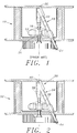
- Fig.1 depicts an analytical centrifuge having a prior art monochromator.
- Fig. 2 illustrates an analytical centrifuge having a monochromator in accordance with one embodiment of the present invention.
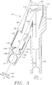
- Fig. 3 is an internal view of the monochromator showing the locations of the surfaces with different optical characteristics.
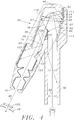
- Fig. 4 illustrates stray light trapping in a region near the diffraction mirror.
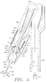
- Fig. 5 illustrates stray light trapping in a region near the monochromator exit.
- a monochromator 30 according to one embodiment of the present invention in an analytical centrifuge 32 is illustrated.
- the set up of the monochromator 30 with respect to the centrifuge 32 is similar to those described in U.S. Patent Nos. 4,830,493; 4,919,537 and 4,921,350 which have been incorporated by reference herein.
- the design of the light tube 34 of the monochromator 30 is significantly different in that the light tube 34 is structured to trap stray light.
- the inside of the light tube 34 of the monochromator 30 is illustrated in simplified form.
- the light tube 34 is made up to two segments 36 and 38 coupled at an elbow 39 in which a diffraction mirror 40 is disposed.
- Some structures have been omitted for clarity, the details of which are found in U.S. Patent Nos. 4,830,493; 4,919,537 and 4,921,350.
- the mirror 40 has a diffraction grating ruled on its surface.
- the mirror 40 is shaped about one axis (along the plane of Fig.3) for the generation of collimated light.
- the cross-section of the segment 36 is round and that of the segment 38 is rectangular.
- Incident light 50 from a light source 44 directed at the mirror 40 diffracts into coherent light of different wavelengths including 0, 1, and higher order components.
- the mirror 40 is provided with a varying curvature and varying spaced rulings so that tilting of the mirror 40 selectively directs light of a particular wavelength range through the exit end 42 of the light tube segment 38 towards the sample.
- An exit slit 48 is used to selectively isolate a narrow band of the light emerging from the exit end 42.
- a motor coupled with a gear mechanism are provided to tilt the mirror 40 between two extreme positions A and B as shown in Fig.3.
- the internal structure of the light tube 34 of the present invention is designed so that it does not reflect or scatter back stray light to the mirror 40 and cause re-diffraction at the wrong wavelength.
- the internal structure is designed also to prevent stray light from mixing with the exit light. This results in the light at the wavelength of interest passing through the monochromator to have very little stray light.
- the wavelength of interest is in the 1 or -1 order.
- the zero order wavelength is typically not used for spectrophotometric studies because of too high intensity and polychromatic. Higher order wavelengths are also not of interest because of possible confusion (overlap) with the primary order wavelengths.
- the inner surface of the light tube 34 is finished or otherwise lined with materials of certain optical characteristics.
- the surfaces have one of three characteristics: (1) very smooth reflective semi-absorbing, (2) semi-smooth reflective semi-absorbing, and (3) rough scattering highly absorbing.
- the first type of surface can be obtained by lining the inside of the light tube 34 using absorptive glass, Cat-A-Lac Gloss or Parson's Black surfaces.
- the second type of surface can be obtained by black anodising the smooth machined inside surface of the light tube 34.
- the third type of surface can be obtained by coating the inside surface of the light tube 34 using a special "optical black" coating developed by Martin Marietta Aerospace Corp.
- the surfaces having the respective characteristics are strategically positioned along the inner walls of the light tube 34 as shown in Fig.3. Generally, the surfaces nearer the mirror 40 have the first characteristic. Further down the segment 38 of the light tube 34 are positioned the surfaces having the third characteristic. Surfaces having the second characteristic are found near the exit end of the segment and any other surfaces not having the first and second characteristics. Because the diffracted light from the mirror is collimated parallel to the plane of Fig.3, the side walls (parallel to plane of Fig. 3) of the rectangular section of the segment 38 (including the elbow portion having surfaces 112 and 114) are exposed to very little stray light and thus can be left as machined surfaces or made to possess the second characteristic.
- the surfaces (flat) 110, 112, 114 and 116 with a high view factor of the diffraction grating mirror 40 have the first characteristic so as to minimize scattering and provide controlled reflection, as will become clear in the discussion below.
- the first characteristic about 10% of incident light is reflected, 0.5% of incident light is diffusely scattered, and the rest of the light is absorbed.
- Such surfaces absorb reflected light and/or diffusely scatter light but not to the mirror because of the absence of view factor to the mirror.
- the general characteristics of the third type of surfaces are reflectance of less than 0.5% over the entire visible region (400-700nm) and less than 0.8% from 300 to 900nm, and light absorbance over a large spectrum (0.27 to 20 microns).
- the rest of the surfaces e.g. 130, 132 etc. near the exit end 42 of the segment 38 which are exposed to light very near the wavelength of interest have the second characteristic.
- some of the surfaces protrude towards the axis of the segment 38.
- the protruding surfaces defines a clearance for passage of light 46 of the desired wavelength reflected from the diffraction mirror 40.
- stray light trapping mechanism of the surfaces will be described separately in Figs. 4 and 5.
- the zero order white light component of stray light is of particular concern because of its high intensity.
- the particular orientation of the mirror 40 between positions A and B would not affect the analysis of the stray light trapping mechanism.
- the light rays shown in the figures are only representative of the paths of light reflected from the mirror 40. The analysis is applicable to all order of light rays reflected from the mirror 40 at any mirror orientation.
- the zero order ray 52 reflects off of surface 114 which is positioned such that the reflected ray 54 misses the mirror 40 before reaching surface 116.
- the ray 54 is reflected off of surface 116 in a ray 56 towards surface 120.
- About 10% of incident light is reflected at the surfaces 114 and 116.
- About 0.5% of incident light on surfaces 114 and 116 is diffusely scattered.
- the rest of the incident light is absorbed by these surfaces.
- the ray 56 is about 1% of the incident ray 52 diffracted from the mirror 40. This 1% of light after being absorbed by highly absorbing surface 120 will have very little light intensity.
- Other light rays from mirror 40 directed at surface 114 will follow a somewhat similar path leading to a substantial reduction of intensity.
- the ray 58 which is directed at surface 112 just beyond surface 114 is reflected along ray 60 and clears the mirror 40 before being reflected at surface 116.
- the reflected ray continues to be reflected between the surfaces 112 and 116, wherein the intensity of the stray light is reduced by 90% each time it is reflected off the surfaces 112 and 116.
- the surface 112 is set at a slightly diverging angle to surface 116, so that the multiple reflections do not converge back to the mirror.
- the transition point between surfaces 114 and 112 is determined by letting the ray 58 just clear the mirror.
- Other rays from the mirror 40 to the surface 112 will also experience multiple reflections, except beyond ray 62 which is reflected at surface 112 to the surface 121 (ray 64).
- the high absorbing surface 121 substantially absorbs the intensity of ray 64.
- Ray 66 is reflected at surface 112 to the inner walls of the light tube segment 36. The multiple reflections occurring in the segment will substantially diminish the stray light
- Stray light 67 from the mirror 40 is reflected at surface 116 to surface 121 (ray 68) and to surface 122 (ray 69) which is substantially absorbed.
- Stray light ray 70 is reflected at surface 110 to surface 122. Any diffuse scattering from surface 122 does not affect the mirror 40 since surface 122 does not have a view factor to the mirror 40. In any event, the diffusely scattered stray light from surface 122 is of low intensity which is further diminished when the scattered light reaches the adjacent light absorbing surfaces. To maintain the clarity of Fig. 4, the reflected or scattered low intensity light rays are not shown in the figure.
- stray light trapped at the lower end of the segment 38 is now discussed.
- Ray 71 from mirror 40 is reflected at surface 130 to surface 122 where the light is substantially absorbed.
- ray 74 is reflected at surface 132 to surface 124 (ray 76) and absorbed.
- the light rays 78 and 80 which are very near the wavelength of interest (ray 46) are respectively reflected at surfaces 138 and 140 to surfaces 134 and 136, respectively.
- the protrusions of surfaces 134 and 136 keep light from reflecting back to the diffraction mirror 40.
- an incident light detector 82 can be placed at the shoulder defined between surfaces 116 and 122 to receive light ray 84 reflected from surface 140.
- This reflected light provides a reference light intensity at a wavelength very close to the desired wavelength of ray 46 for the spectrophotometric analysis.
- the protruding corners of surfaces 134, 136, 138 and 140, and corners 142 and 144 shield the mirror 40 from the light rays 90 and 92 reflected from the window 150 of the sample cell in the rotor. These corners also shields the incident detector 82 from light reflected from the window 150.
- the surfaces may be substituted with surfaces of other characteristics which can also accomplish the same stray light trapping tasks e.g. substituting the third type of surfaces for the second type, except that the third type of surfaces are more expensive to make. Accordingly, it is to be understood that the invention is not to be limited by the specific illustrated embodiments, but only by the scope of the appended claims.
Landscapes
- Physics & Mathematics (AREA)
- Spectroscopy & Molecular Physics (AREA)
- General Physics & Mathematics (AREA)
- Optics & Photonics (AREA)
- Spectrometry And Color Measurement (AREA)
- Optical Measuring Cells (AREA)
Applications Claiming Priority (2)
| Application Number | Priority Date | Filing Date | Title |
|---|---|---|---|
| US07/641,202 US5123740A (en) | 1991-01-15 | 1991-01-15 | Stray light trap in a monochrometer |
| US641202 | 1991-01-15 |
Publications (2)
| Publication Number | Publication Date |
|---|---|
| EP0495569A2 true EP0495569A2 (de) | 1992-07-22 |
| EP0495569A3 EP0495569A3 (en) | 1993-02-24 |
Family
ID=24571365
Family Applications (1)
| Application Number | Title | Priority Date | Filing Date |
|---|---|---|---|
| EP19920300078 Ceased EP0495569A3 (en) | 1991-01-15 | 1992-01-06 | Stray light trap in a monochromator |
Country Status (3)
| Country | Link |
|---|---|
| US (1) | US5123740A (de) |
| EP (1) | EP0495569A3 (de) |
| JP (1) | JP3184279B2 (de) |
Cited By (8)
| Publication number | Priority date | Publication date | Assignee | Title |
|---|---|---|---|---|
| US5859703A (en) * | 1996-05-17 | 1999-01-12 | Pfizer Inc. | Spectrophotometric analysis |
| WO2001040746A1 (en) * | 1999-12-01 | 2001-06-07 | Hach Company | Concentric spectrometer with mitigation of internal specular reflections |
| EP1081473A3 (de) * | 1999-09-04 | 2003-10-01 | Acterna Eningen GmbH | Optischer Spektrumanalysator |
| WO2005050255A3 (en) * | 2003-11-24 | 2006-04-20 | Boing Company | High performance system and method for capturing and absorbing radiation |
| EP1643224A3 (de) * | 2004-09-30 | 2006-06-07 | GretagMacbeth, LLC | Verfahren und Vorrichtung für verbesserte Kolorimetrie |
| US7071444B2 (en) | 2003-11-24 | 2006-07-04 | The Boeing Company | High performance system and method for capturing and absorbing radiation |
| EP1772714A3 (de) * | 2005-02-15 | 2007-08-15 | GretagMacbeth, LLC | System und Verfahren zur Anwendung von Korrekturfaktoren in Bezug auf Umgebungsbedingungen |
| US7499163B2 (en) | 2005-02-15 | 2009-03-03 | X-Rite Europe Gmbh | System and method for applying correction factors related to ambient conditions |
Families Citing this family (7)
| Publication number | Priority date | Publication date | Assignee | Title |
|---|---|---|---|---|
| US5790281A (en) * | 1996-10-02 | 1998-08-04 | Xerox Corporation | Method of correcting the measured reflectance of an image acquired by an image acquisition device for the integrating cavity effect |
| US20050058413A1 (en) * | 2003-08-26 | 2005-03-17 | Poulsen Peter Davis | Light-absorbing surface and method |
| US7209230B2 (en) | 2004-06-18 | 2007-04-24 | Luckoff Display Corporation | Hand-held spectra-reflectometer |
| US7233394B2 (en) | 2005-06-20 | 2007-06-19 | Luckoff Display Corporation | Compact spectrometer |
| JP5161755B2 (ja) | 2008-12-25 | 2013-03-13 | 浜松ホトニクス株式会社 | 分光測定装置、分光測定方法、及び分光測定プログラム |
| JP2010261767A (ja) | 2009-05-01 | 2010-11-18 | Canon Inc | 分光装置及びそれを有する画像形成装置 |
| US10641656B1 (en) * | 2018-12-20 | 2020-05-05 | Shimadzu Corporation | Spectrometer and incident light limiting member to be used for the same |
Family Cites Families (7)
| Publication number | Priority date | Publication date | Assignee | Title |
|---|---|---|---|---|
| FR2087647A5 (de) * | 1970-05-27 | 1971-12-31 | Anvar | |
| DE2924125C2 (de) * | 1979-06-15 | 1982-10-28 | Bodenseewerk Perkin-Elmer & Co GmbH, 7770 Überlingen | Einrichtung zur Unterdrückung von Streulicht bei Gittermonochromatoren |
| FR2477288A1 (fr) * | 1980-03-03 | 1981-09-04 | Vidal Bernard | Piege a lumiere a discrimination angulaire |
| US4919537A (en) * | 1987-10-29 | 1990-04-24 | Beckman Instruments Inc. | UV scanning system for centrifuge |
| US4830493A (en) * | 1987-10-29 | 1989-05-16 | Beckman Instruments, Inc. | UV scanning system for centrifuge |
| US4921350A (en) * | 1989-02-10 | 1990-05-01 | Beckman Instruments, Inc. | Monochromator second order subtraction method |
| US5128549A (en) * | 1990-03-30 | 1992-07-07 | Beckman Instruments, Inc. | Stray radiation compensation |
-
1991
- 1991-01-15 US US07/641,202 patent/US5123740A/en not_active Expired - Fee Related
-
1992
- 1992-01-06 EP EP19920300078 patent/EP0495569A3/en not_active Ceased
- 1992-01-13 JP JP02161592A patent/JP3184279B2/ja not_active Expired - Lifetime
Cited By (9)
| Publication number | Priority date | Publication date | Assignee | Title |
|---|---|---|---|---|
| US5859703A (en) * | 1996-05-17 | 1999-01-12 | Pfizer Inc. | Spectrophotometric analysis |
| EP1081473A3 (de) * | 1999-09-04 | 2003-10-01 | Acterna Eningen GmbH | Optischer Spektrumanalysator |
| WO2001040746A1 (en) * | 1999-12-01 | 2001-06-07 | Hach Company | Concentric spectrometer with mitigation of internal specular reflections |
| WO2005050255A3 (en) * | 2003-11-24 | 2006-04-20 | Boing Company | High performance system and method for capturing and absorbing radiation |
| US7071444B2 (en) | 2003-11-24 | 2006-07-04 | The Boeing Company | High performance system and method for capturing and absorbing radiation |
| EP1643224A3 (de) * | 2004-09-30 | 2006-06-07 | GretagMacbeth, LLC | Verfahren und Vorrichtung für verbesserte Kolorimetrie |
| US7372571B2 (en) | 2004-09-30 | 2008-05-13 | Gretegmacbeth, Llc | Color sensing apparatus |
| EP1772714A3 (de) * | 2005-02-15 | 2007-08-15 | GretagMacbeth, LLC | System und Verfahren zur Anwendung von Korrekturfaktoren in Bezug auf Umgebungsbedingungen |
| US7499163B2 (en) | 2005-02-15 | 2009-03-03 | X-Rite Europe Gmbh | System and method for applying correction factors related to ambient conditions |
Also Published As
| Publication number | Publication date |
|---|---|
| JPH0560613A (ja) | 1993-03-12 |
| EP0495569A3 (en) | 1993-02-24 |
| JP3184279B2 (ja) | 2001-07-09 |
| US5123740A (en) | 1992-06-23 |
Similar Documents
| Publication | Publication Date | Title |
|---|---|---|
| EP0495569A2 (de) | Lichtfalle für Streulicht in einem Monochromator | |
| US5127729A (en) | Method and apparatus for guiding and collecting light in photometry or the like | |
| US6120166A (en) | Light source apparatus for a spectral analyzer | |
| US5153679A (en) | Apparatus and process for measuring light absorbance or fluorescence in liquid samples | |
| US20050270524A1 (en) | Broadband wavelength selective filter | |
| US5009493A (en) | Mirror arrangement for a beam path in a multiple-reflection measuring cell | |
| US4429225A (en) | Infrared thickness measuring device | |
| US4575243A (en) | Monochromator | |
| US5880831A (en) | Reflectance spectrophotometric apparatus with optical relay | |
| US7936454B2 (en) | Three mirror anastigmat spectrograph | |
| JPS62201325A (ja) | 赤外線検知器 | |
| Coltman et al. | Physical Properties of Calcium Tungstate X‐Ray Screens | |
| JP2003515733A (ja) | 内部鏡面反射を軽減する同心分光計 | |
| AU609279B2 (en) | New optical system for a multidetector array spectrograph | |
| EP0422448B1 (de) | Vorrichtung zum Messen der Lichtabsorption oder Fluoreszenz in flüssigen Proben | |
| JPH0131130B2 (de) | ||
| US4300835A (en) | Attenuator for stray light produced in monochromators | |
| US4025196A (en) | Asymmetric double pass grating monochromator | |
| Cruddace et al. | Measurements of the normal-incidence X-ray reflectance of a molybdenum-silicon multilayer deposited on a 2000 l/mm grating | |
| US3775010A (en) | Assymmetric double pass grating monochromator | |
| US4037974A (en) | Sample cell for spectrophotometers | |
| US2945953A (en) | Grating spectrometers | |
| KR100970244B1 (ko) | 적분구 탑재형 분광 광도계 | |
| CN114544675A (zh) | 一种带通分光的x射线光学系统及膜层分布确定方法 | |
| JPS62220834A (ja) | 光分析装置 |
Legal Events
| Date | Code | Title | Description |
|---|---|---|---|
| PUAI | Public reference made under article 153(3) epc to a published international application that has entered the european phase |
Free format text: ORIGINAL CODE: 0009012 |
|
| AK | Designated contracting states |
Kind code of ref document: A2 Designated state(s): DE FR GB IT |
|
| PUAL | Search report despatched |
Free format text: ORIGINAL CODE: 0009013 |
|
| AK | Designated contracting states |
Kind code of ref document: A3 Designated state(s): DE FR GB IT |
|
| 17P | Request for examination filed |
Effective date: 19930428 |
|
| 17Q | First examination report despatched |
Effective date: 19931228 |
|
| APAB | Appeal dossier modified |
Free format text: ORIGINAL CODE: EPIDOS NOAPE |
|
| 18R | Application refused |
Effective date: 19951222 |
|
| APAF | Appeal reference modified |
Free format text: ORIGINAL CODE: EPIDOSCREFNE |