EP0495182A2 - System und Verfahren zur Übereinstimmungslagebestimmung von Konstellationen - Google Patents
System und Verfahren zur Übereinstimmungslagebestimmung von Konstellationen Download PDFInfo
- Publication number
- EP0495182A2 EP0495182A2 EP91119967A EP91119967A EP0495182A2 EP 0495182 A2 EP0495182 A2 EP 0495182A2 EP 91119967 A EP91119967 A EP 91119967A EP 91119967 A EP91119967 A EP 91119967A EP 0495182 A2 EP0495182 A2 EP 0495182A2
- Authority
- EP
- European Patent Office
- Prior art keywords
- detected
- points
- creating
- matches
- coordinates
- Prior art date
- Legal status (The legal status is an assumption and is not a legal conclusion. Google has not performed a legal analysis and makes no representation as to the accuracy of the status listed.)
- Withdrawn
Links
Images


Classifications
-
- G—PHYSICS
- G01—MEASURING; TESTING
- G01S—RADIO DIRECTION-FINDING; RADIO NAVIGATION; DETERMINING DISTANCE OR VELOCITY BY USE OF RADIO WAVES; LOCATING OR PRESENCE-DETECTING BY USE OF THE REFLECTION OR RERADIATION OF RADIO WAVES; ANALOGOUS ARRANGEMENTS USING OTHER WAVES
- G01S13/00—Systems using the reflection or reradiation of radio waves, e.g. radar systems; Analogous systems using reflection or reradiation of waves whose nature or wavelength is irrelevant or unspecified
- G01S13/02—Systems using reflection of radio waves, e.g. primary radar systems; Analogous systems
- G01S13/06—Systems determining position data of a target
-
- G—PHYSICS
- G06—COMPUTING; CALCULATING OR COUNTING
- G06V—IMAGE OR VIDEO RECOGNITION OR UNDERSTANDING
- G06V10/00—Arrangements for image or video recognition or understanding
- G06V10/70—Arrangements for image or video recognition or understanding using pattern recognition or machine learning
- G06V10/74—Image or video pattern matching; Proximity measures in feature spaces
- G06V10/75—Organisation of the matching processes, e.g. simultaneous or sequential comparisons of image or video features; Coarse-fine approaches, e.g. multi-scale approaches; using context analysis; Selection of dictionaries
- G06V10/757—Matching configurations of points or features
Definitions
- This invention relates to systems and methods for pattern matching and, more particularly, to a system and method for matching a set of detected points to a set of reference points in real time.
- a system and method for matching a set of detected points to a reference point pattern.
- This system includes a programmable processor for storing the coordinates of reference points from the reference pattern. These reference coordinates are defined in a reference frame.
- the processor stores the coordinates of the detected points.
- the detected coordinates are defined in a detected coordinate frame.
- the points in the reference coordinate frame are transformed to the detected coordinate frame using an apriori coordinate transform.
- Vector tables of each possible ordered pair of reference points and detected points are then created.
- a list of pairs of matched reference and detected vectors is constructed.
- the criteria for matching vectors is that the magnitude of the difference vectors between pairs of reference and detected vectors is less than a predetermined threshold.
- a match matrix histogram is then created which contains bins for counting each Detection - Reference point correspondence generated by relating the Heads and Tails of the matched Detection - Reference vector pairs. Finally, matches are selected in the matrix by eliminating less probable matches based upon the number of counts in the bins and the geometrical consistency of the implied point matches.
- a reference point storage means 12 contains coordinates for the reference points in a well defined coordinate system.
- the coordinates of the specific point of interest are also supplied to the reference point storage means 12.
- the coordinates of the reference points and the specific point (aimpoint) are transmitted to a constellation matching processor 14.
- the general approach of the present invention is to proceed in four basic steps: Initialization, Detection, Matching and Update.
- the constellation matching processor 14 will perform all computations that can be performed prior to the knowledge of the detection points.
- a sensor 16 will then provide coordinates of detected points (in a detection coordinate system) to the constellation matching processor 14.
- the sensor 16 may be gathering radar, IR, or other information to generate detected point coordinates.
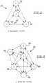
- FIG. 2 a simple constellation 20 consisting of four reference points 22 is shown.
- An aim point 24 is located in a given, fixed, known location with respect to the orientation of the constellation 20. Coordinates for each of the points 22 and as well as the aimpoint 24 are given in a particular reference coordinate system.
- FIG. 3 shows a set 26 of six detected points 28.
- the detected points 28 are defined by coordinates in a detected reference frame.
- An apriori encounter geometry is specified; thus, the angle of bearing of the detected coordinate frame is known with respect to the reference coordinate frame.
- An appropriate coordinate transformation is established and the supplied reference coordinates are converted to the apriori detection coordinate frame.
- These points are referred to as the REF coordinates of the reference points.
- a North, East orientation for X, Y with an arbitrary origin is used.
- the apriori encounter bearing (angle relative to North) will set the internal X axis orientation.
- the storage depth (along the X axis) required to encompass the reference image is computed and the "extinction" criteria are established for detection points.
- a potential match threshold is established which will define counts in a potential match histogram based upon the number of reference points supplied and the apriori probability of point detection.
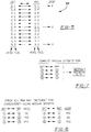
- a potential match matrix 30 is constructed with all of its bins set to 0.
- the rows 32 in the matrix correspond to detected (DET) points and columns 34 in the matrix 30 correspond to REF points.
- Other miscellaneous constants, tables and variables which require Initialization are established and initialized during this period. Also, data needed for aimpoint estimation which can be pre-computed for all outcomes of the matching process can be made and stored at this time.
- a new row 32 in the match matrix 30 is selected from a list of available free rows and the row is designated as "in use”.
- a set of vectors are then established for each possible pair of detected points. Vectors go from each of the old "non-extinct" points to the new point.
- a vector match is attempted between each DET vector and each REF vector. A match between two vectors occurs when the length of their difference vector is less than a predetermined threshold.
- a preliminary screening of match attempts is accomplished using a look-up procedure.
- the DET vector space is partitioned into a predetermined number of rectangular regions.
- this list 36 of vector matches is shown.
- the first entry in the list of vector matches indicates that the vector beginning at detected point 1 and ending with detected point 2 in FIG. 3 has been found to match with the vector beginning with reference point 1 and ending with reference point 3 shown in FIG. 2. From visual inspection it can be seen that these vectors are roughly the same length and direction.
- the first entry in the vector match list 36 will yield a match between detected point number 2 and reference point number 3 and also between detected point number 1 and reference point number 1.
- the match matrix 30 in FIG. 4 will accordingly have its bins incremented to tabulate these results.
- a 1 appears at the intersection of the row for detected point number 2 and the column for reference point number 3.
- a 1 is placed in the bin at the intersection of the row for detected point number 1 and the column for reference point number 1.
- the histogram matrix 30 shows the results of tabulating all matches found in the vector match table 36. It can be seen in the match matrix 30 that for certain detection and reference points there were no matches and that for some there were a maximum of three matches.
- the match matrix 30 is now scanned to determine the maximum value contained (MAX).
- MAX maximum value contained
- a potential match threshold was established. For example, as shown in FIG. 4, this threshold is established to be 2.25. Now, the MAX, which is equal to 3, is compared to the match threshold. If this MAX is less then the potential match threshold, then the matching process terminates for this attempt without finding the reference pattern. Otherwise a bin retention threshold is established and the process continues below. As shown in FIG. 4, the MAX is greater than the threshold and the bin retention threshold (REQ) is calculated as half the MAX, or 1.5.
- REQ bin retention threshold
- the match matrix 30 is scanned again and any bin count which falls below the established threshold has its corresponding bin in a new refined potential match matrix 38 shown in FIG. 6, set to -1 (all other bins are set to 0). This flags the matrix refinement process to exclude "weak" vector matches which would normally increment this bin. Thus, each of the bins in FIG. 4 having only a 1, do not meet the 1.5 retention threshold and are underlined. Likewise, in the vector match table 36 in FIG. 5, these matches are identified under the column labeled "drop".
- the refined potential match matrix 38 is completed by scanning the list of current vector matches and incrementing the two corresponding bins only if neither bin to be incremented is currently negative. This eliminates the underlined bins in the match matrix 30 and may reduce the counts in other bins as well in the refined potential match matrix. It should be noted that the BIN'S do not get reduced directly. They do get reduced indirectly via the refinement process. Since 2 BIN'S are eliminated for each vector match that is eliminated, other BIN'S can be reduced also.
- the refined potential match matrix 38 is scanned to determine the maximum value (MAX) contained. The maximum value for each row plus the sum of the row entries is also determined for this scan. The column index for the maximum bin in each row is then determined. If more than one entry is at the row maximum value, the column index is set to minus one.
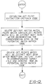
- the final point matches are selected by transforming each potential REF match point to the DET frame using the preliminary transformations defined above. That is, the median offset vector is added to REF point coordinates to estimate their expected DET frame values. The corresponding DET match point is checked for spatial consistency (the length of the difference vector lies within a predetermined tolerance). The potential matches to be tested during this final path are those whose non-zero bin values are equal to their row maximums. A list of final point matches and a final match count is then generated. This process is illustrated in FIG. 8.
- Detected points which have become extinct must be eliminated. This is accomplished by decrementing the appropriate bins in the permanent potential match matrix which arose from the extinct point then, by removing the corresponding vectors which contain the extinct point as an end point from the vector match list, and then by removing the point from the list of current detection points. Further, the rows of the matrix and the point and vector lists should be appropriately compressed. The actual compression may be by chain pointer modification. The vacated rows should contain all zeros.
- FIGS. 9a-b through 12 are flowcharts of the above-described process.
- the Initialization period is summarized in the flowchart in FIG. 9.
- the Detection process is summarized in the flowchart in FIG. 10.
- the Matching Process is summarized in FIGS. 11a-b and the Update Process is summarized in the flowchart in FIG. 12.
- a more generalized transformation may also be used.
- a least squares fit estimate of a transformation matrix that includes rotation and scale and shift (as well as perspective) may be employed.
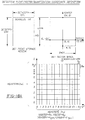
- FIG. 13A shows five reference points and two aimpoints.
- FIG. 13B shows the rotation of the coordinates by a bearing angle of 90° after rotation.
- FIG. 14 indicates the coordinates of the input reference point table upon rotation, the coordinates become the reference point table coordinates indicated in FIG. 15.
- FIG. 16 indicates the reference aimpoint table and FIG. 17, the coordinates of the reference aimpoint table upon rotation by 90°.
- This table consists of consecutive lists of REF vector indices which could potentially match DET vectors falling in the corresponding quantization BIN. Lists for BINS are stacked contiguously in the table.
- a Reference Vector Table is now created which contains all of the ordered pairs of reference points after eliminating those vectors having an XV less than XV cut-off where XV cut-off is equal to -75. In particular eight possible vectors were eliminated and 12 remain as shown in FIG. 19.
- FIG 18 contains the Detection Point/Vector/Quantization coordinate definition tables as well as the constraints used in this example.
- the quantization pointer table and matchable reference vectors table are shown in FIG. 20.
- the purpose of quantization is to speed-up throughput. If all possible vector matches were tried, the number of trials would get very large due to the combinatorics. Since there are really very few vectors that are close to matching, the process can be streamlined by using quantization. Thus, all combinations of the reference points are used to make reference vectors and then they are divided up into quantized bins. Then for each quantization bin, a list of indices for all REF vectors which could possible match any DET vector corresponding to that bin is stored in a table.
- the quantization pointer table provides a way of looking things up quickly. If enough memory were reserved to handle all possible matches, it would consume a great deal of memory storage space.
- FIG. 21 shows the detection points linked list.
- FIG. 22 shows the DET/REF vector match linked list which is the set of all vector pairs that matched based on their difference vectors being small enough.
- FIG. 25 shows the refined potential match matrix row statistics which are used for active rows to determine where conflicts exist.
- FIG. 25 also shows the offset vector table.
- FIG. 26 is the final point match table indicating that five matches were found. To estimate the detection frame aimpoint coordinates in this simple case, the median REF to DET frame offsets are used. This yields the aimpoint coordinates shown in FIG. 27.
- the constellation matching system 10 can be used for matching a set of reference points with a second set of detected points in a wide variety of settings. Also, the present invention can be used in real-time in many applications. While the above description constitutes the preferred embodiments of the present invention, it will be appreciated that the invention is susceptible to modifications, variation and change without departing from the proper scope and fair meaning of the accompanying claims.
Landscapes
- Engineering & Computer Science (AREA)
- Theoretical Computer Science (AREA)
- Computer Vision & Pattern Recognition (AREA)
- Remote Sensing (AREA)
- Physics & Mathematics (AREA)
- Radar, Positioning & Navigation (AREA)
- General Physics & Mathematics (AREA)
- Medical Informatics (AREA)
- Computing Systems (AREA)
- Software Systems (AREA)
- Artificial Intelligence (AREA)
- General Health & Medical Sciences (AREA)
- Evolutionary Computation (AREA)
- Multimedia (AREA)
- Databases & Information Systems (AREA)
- Health & Medical Sciences (AREA)
- Computer Networks & Wireless Communication (AREA)
- Image Analysis (AREA)
- Image Processing (AREA)
- Monitoring And Testing Of Transmission In General (AREA)
Applications Claiming Priority (2)
| Application Number | Priority Date | Filing Date | Title |
|---|---|---|---|
| US07/628,963 US5218648A (en) | 1990-12-17 | 1990-12-17 | Constellation matching system and method |
| US628963 | 1990-12-17 |
Publications (2)
| Publication Number | Publication Date |
|---|---|
| EP0495182A2 true EP0495182A2 (de) | 1992-07-22 |
| EP0495182A3 EP0495182A3 (en) | 1993-09-15 |
Family
ID=24521028
Family Applications (1)
| Application Number | Title | Priority Date | Filing Date |
|---|---|---|---|
| EP19910119967 Withdrawn EP0495182A3 (en) | 1990-12-17 | 1991-11-22 | Constellation matching system and method |
Country Status (10)
| Country | Link |
|---|---|
| US (1) | US5218648A (de) |
| EP (1) | EP0495182A3 (de) |
| JP (1) | JPH04293178A (de) |
| KR (1) | KR940011329B1 (de) |
| AU (1) | AU640839B2 (de) |
| CA (1) | CA2055073C (de) |
| IL (1) | IL100027A0 (de) |
| NO (1) | NO914656L (de) |
| TR (1) | TR26172A (de) |
| TW (1) | TW200584B (de) |
Cited By (1)
| Publication number | Priority date | Publication date | Assignee | Title |
|---|---|---|---|---|
| WO2001046909A1 (en) * | 1999-12-21 | 2001-06-28 | Snap-On Technologies, Inc. | Method and apparatus of automatically identifying faults in a machine vision measuring system |
Families Citing this family (8)
| Publication number | Priority date | Publication date | Assignee | Title |
|---|---|---|---|---|
| US5954583A (en) * | 1992-11-05 | 1999-09-21 | Com21 Limited | Secure access control system |
| US6104828A (en) * | 1994-03-24 | 2000-08-15 | Kabushiki Kaisha Topcon | Ophthalmologic image processor |
| US6405036B1 (en) * | 1997-09-29 | 2002-06-11 | Telefonaktiebolaget Lm Ericsson (Publ) | Method and arrangement in a telecommunication system |
| US5999117A (en) * | 1998-06-16 | 1999-12-07 | Northrop Grumman Corporation | Method for tracking and detecting turns of maneuvering targets |
| WO2002095621A2 (en) * | 2001-05-23 | 2002-11-28 | City University London | Method for pattern discovery in a multidimensional numerical dataset |
| US8620083B2 (en) * | 2004-12-03 | 2013-12-31 | Google Inc. | Method and system for character recognition |
| US20080049863A1 (en) * | 2006-08-28 | 2008-02-28 | Nokia Corporation | Apparatus, method and computer program product providing soft decision generation with lattice reduction aided MIMO detection |
| GB201020530D0 (en) | 2010-12-03 | 2011-01-19 | Optos Plc | Method of identifying anomalies in images |
Citations (1)
| Publication number | Priority date | Publication date | Assignee | Title |
|---|---|---|---|---|
| US4891762A (en) * | 1988-02-09 | 1990-01-02 | Chotiros Nicholas P | Method and apparatus for tracking, mapping and recognition of spatial patterns |
Family Cites Families (5)
| Publication number | Priority date | Publication date | Assignee | Title |
|---|---|---|---|---|
| SE411400B (sv) * | 1977-11-02 | 1979-12-17 | Saab Scania Ab | For foljning av ett objekt avsedd korrelationsfoljare |
| DE2914693C2 (de) * | 1979-04-11 | 1982-05-27 | Messerschmitt-Bölkow-Blohm GmbH, 8000 München | Vorrichtung zur Präzisionsnavigation |
| US4736437A (en) * | 1982-11-22 | 1988-04-05 | View Engineering, Inc. | High speed pattern recognizer |
| GB8710737D0 (en) * | 1987-05-06 | 1987-06-10 | British Telecomm | Video image encoding |
| AU651678B2 (en) * | 1991-04-08 | 1994-07-28 | Commonwealth Of Australia, The | Ray tracing technique for coordinate registration |
-
1990
- 1990-12-17 US US07/628,963 patent/US5218648A/en not_active Expired - Lifetime
-
1991
- 1991-11-06 CA CA002055073A patent/CA2055073C/en not_active Expired - Fee Related
- 1991-11-11 IL IL100027A patent/IL100027A0/xx unknown
- 1991-11-22 EP EP19910119967 patent/EP0495182A3/en not_active Withdrawn
- 1991-11-23 TW TW080109223A patent/TW200584B/zh active
- 1991-11-27 NO NO91914656A patent/NO914656L/no unknown
- 1991-12-13 AU AU89721/91A patent/AU640839B2/en not_active Ceased
- 1991-12-16 KR KR1019910023101A patent/KR940011329B1/ko not_active IP Right Cessation
- 1991-12-16 JP JP3331967A patent/JPH04293178A/ja active Pending
- 1991-12-17 TR TR91/1181A patent/TR26172A/xx unknown
Patent Citations (1)
| Publication number | Priority date | Publication date | Assignee | Title |
|---|---|---|---|---|
| US4891762A (en) * | 1988-02-09 | 1990-01-02 | Chotiros Nicholas P | Method and apparatus for tracking, mapping and recognition of spatial patterns |
Non-Patent Citations (1)
| Title |
|---|
| PATTERN RECOGNITION vol. 4, 1972, ELMSFORD, NY US pages 73 - 81 J.C. SIMON ET AL. 'A Method of Comparing Two Patterns Independent of Possibla Transformations and Small Distortions' * |
Cited By (3)
| Publication number | Priority date | Publication date | Assignee | Title |
|---|---|---|---|---|
| WO2001046909A1 (en) * | 1999-12-21 | 2001-06-28 | Snap-On Technologies, Inc. | Method and apparatus of automatically identifying faults in a machine vision measuring system |
| US6323776B1 (en) | 1999-12-21 | 2001-11-27 | Snap-On Technologies, Inc. | Method and apparatus of automatically identifying faults in a machine vision measuring system |
| KR100722489B1 (ko) * | 1999-12-21 | 2007-05-29 | 스넵-온 테크놀로지스 인코포레이티드 | 기계 관찰 측정 시스템의 고장을 자동적으로 식별하는 방법 및 장치 |
Also Published As
| Publication number | Publication date |
|---|---|
| KR940011329B1 (ko) | 1994-12-05 |
| TW200584B (de) | 1993-02-21 |
| IL100027A0 (en) | 1992-08-18 |
| CA2055073C (en) | 1994-09-20 |
| NO914656L (no) | 1992-06-18 |
| EP0495182A3 (en) | 1993-09-15 |
| AU640839B2 (en) | 1993-09-02 |
| CA2055073A1 (en) | 1992-06-18 |
| TR26172A (tr) | 1995-02-15 |
| JPH04293178A (ja) | 1992-10-16 |
| KR920012944A (ko) | 1992-07-28 |
| US5218648A (en) | 1993-06-08 |
| NO914656D0 (no) | 1991-11-27 |
| AU8972191A (en) | 1992-06-25 |
Similar Documents
| Publication | Publication Date | Title |
|---|---|---|
| Breuel | Fast recognition using adaptive subdivisions of transformation space | |
| US6023530A (en) | Vector correlation system for automatically locating patterns in an image | |
| US7397970B2 (en) | Automatic scene correlation and identification | |
| David et al. | Softposit: Simultaneous pose and correspondence determination | |
| US5093869A (en) | Pattern recognition apparatus utilizing area linking and region growth techniques | |
| US6278798B1 (en) | Image object recognition system and method | |
| US5170440A (en) | Perceptual grouping by multiple hypothesis probabilistic data association | |
| EP0807297B1 (de) | Verfahren und gerät zum trennen des vordergrunds und hintergrunds in textenthaltenden bildern | |
| JP2710062B2 (ja) | 出力候補数決定方式 | |
| US5063524A (en) | Method for estimating the motion of at least one target in a sequence of images and device to implement this method | |
| CN106971401B (zh) | 多目标跟踪装置和方法 | |
| EP0386181B1 (de) | Maskierbarer zweistufen korrelator | |
| EP0495182A2 (de) | System und Verfahren zur Übereinstimmungslagebestimmung von Konstellationen | |
| CA2102767C (en) | Identifying curves within a scanned image | |
| CN101553825B (zh) | 基于字典模式来识别输入模式的模式识别设备 | |
| US6658149B1 (en) | Scheme for identifying gray-scale image | |
| EP0877335B1 (de) | Verfahren und Vorrichtung zur Zeichenerkennung | |
| Guil et al. | Bidimensional shape detection using an invariant approach | |
| US20090129699A1 (en) | Image processing system | |
| CA2263734C (en) | Method for performing character recognition on a pixel matrix | |
| Ayala et al. | Moving target tracking using symbolic registration | |
| US20040013299A1 (en) | System and method for contrast enhanced registration with complex polynomial interpolation | |
| Stockman et al. | 2D object acquisition using circular scanning | |
| Laiche et al. | Geometric based histograms for shape representation and retrieval | |
| JP3344791B2 (ja) | 線分抽出方法 |
Legal Events
| Date | Code | Title | Description |
|---|---|---|---|
| PUAI | Public reference made under article 153(3) epc to a published international application that has entered the european phase |
Free format text: ORIGINAL CODE: 0009012 |
|
| AK | Designated contracting states |
Kind code of ref document: A2 Designated state(s): CH DE ES FR GB GR IT LI NL SE |
|
| PUAL | Search report despatched |
Free format text: ORIGINAL CODE: 0009013 |
|
| AK | Designated contracting states |
Kind code of ref document: A3 Designated state(s): CH DE ES FR GB GR IT LI NL SE |
|
| 17P | Request for examination filed |
Effective date: 19940314 |
|
| STAA | Information on the status of an ep patent application or granted ep patent |
Free format text: STATUS: THE APPLICATION IS DEEMED TO BE WITHDRAWN |
|
| 18D | Application deemed to be withdrawn |
Effective date: 19960601 |