EP0494600B1 - Method and device for rolling dough into balls - Google Patents
Method and device for rolling dough into balls Download PDFInfo
- Publication number
- EP0494600B1 EP0494600B1 EP92100044A EP92100044A EP0494600B1 EP 0494600 B1 EP0494600 B1 EP 0494600B1 EP 92100044 A EP92100044 A EP 92100044A EP 92100044 A EP92100044 A EP 92100044A EP 0494600 B1 EP0494600 B1 EP 0494600B1
- Authority
- EP
- European Patent Office
- Prior art keywords
- kneading
- vee
- actuator
- trough
- dough
- Prior art date
- Legal status (The legal status is an assumption and is not a legal conclusion. Google has not performed a legal analysis and makes no representation as to the accuracy of the status listed.)
- Expired - Lifetime
Links
Images


Classifications
-
- A—HUMAN NECESSITIES
- A21—BAKING; EDIBLE DOUGHS
- A21C—MACHINES OR EQUIPMENT FOR MAKING OR PROCESSING DOUGHS; HANDLING BAKED ARTICLES MADE FROM DOUGH
- A21C7/00—Machines which homogenise the subdivided dough by working other than by kneading
- A21C7/01—Machines which homogenise the subdivided dough by working other than by kneading with endless bands
Definitions
- the invention relates to a method and a device for circular kneading of dough with a cross-sectionally approximately V-shaped knitting channel, the two V-legs of which are formed by a first and a second knitting belt in a corresponding arrangement.
- the V-shaped profile of the knitting channel is blunted by a fixed base plate.
- the angle of inclination of one of the conveyor belts or knitting belts with respect to this base plate can, however, only be determined before knitting operation in view of the present dough piece sizes.
- the problem on which the invention is based is therefore raised of a circular knitter with a V-like knitting channel create, the cross section can be changed dynamically and with little design effort during continuous operation, so that a uniform pressure is exerted in particular on the dough being processed.
- the circular knitter should be equally suitable for processing rye and / or pure wheat dough and should allow the formation of a kneading or knitting skin on the dough, the kneading of fermentation bubbles and a uniform dough tension in a satisfactory manner.
- the invention proposes in a method with the features mentioned at the outset to connect the knitting or conveyor belts in the region of the apex line of the knitting channel with a hinge joint and to provide them with a motorized actuator for pivoting them against one another, which acts on one or both knitting or conveyor belts and changes their V-angle constantly and / or dynamically during active operation.
- the two conveyor belts which are expediently steered or hinged to one another at their longitudinal edges, are pivoted dynamically to one another and from one another by means of the actuating element during active operation, like the cutting edges of scissors.
- the actuator is best controlled periodically so that pressure is applied uniformly or symmetrically to the entire dough being conveyed, so that an optimal effective result is achieved.
- the actuator expediently engages the free ends of the cross-sectional V-legs of the active channel.
- the knitting channel is provided with dough guiding elements in the region of its free edges or boundaries.
- These can advantageously be designed as kneading or knitting elements, which are made of wood, for example, and protrude from the free edges such that the upper opening of the cross-sectional V-shaped profile of the knitting channel is narrowed.
- the V-shape of the kneading channel would produce a conical dough piece when kneaded.
- one or more linear slides are provided according to a special design, which lead to the V-apex of the active channel and receive the guide elements in a displaceably mounted manner.
- the linear slide is arranged in such a way that the guide element accommodated therein can be moved along the active surface of the V-channel.
- the problem of the specific implementation of the actuator arises.
- this is provided with a rod which is articulated on one of the two V-shaped active and / or conveyor belts and is also coupled to a drive unit which gives the rod lifting movements and is fixed in place on or with respect to the other conveyor belt.
- the drive unit has a rotatable disc on which the rod is eccentrically articulated.
- the displacement or eccentricity of the articulation point is advantageously adjustable or displaceable on the disk relative to its center.
- the disk has a radial elongated hole in which the articulation can be fixed by means of a locking screw.
- the drive unit necessary for the conveyor belt can also be used for the actuator use; in other words, the drive unit for the actuator is (structurally) integrated with that for the conveyor belt.
- a further embodiment of the invention is that the chassis of the knitting device has one or more, preferably mutually perpendicular linear guides, in which the actuator is slidably mounted.
- a horizontal linear guide allows the maximum and minimum opening angle of the active channel and its lifting rest position to be adapted to the respective requirements;
- a vertical linear guide allows the angular stroke with which the active channel is narrowed or widened during operation to be increased and decreased as required.
- the knitting channel is provided, which are preferably cranked outwards. Through the offset, additional space protruding from the active channel for attaching the structural components is obtained.
- the adjustability of the width of the active channel makes it easier if, in another development of the invention, the actuating or.
- the lifting rod is articulated in an elongated hole on the cross-sectional V-leg, the articulation point being displaceable and lockable in the longitudinal direction of this elongated hole.
- This slot can advantageously be formed in one of the mounting plates or frames mentioned.
- a strand, for. B. round steel provided, which lies in the knitting channel above the hinge axis.
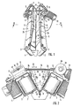
- the circular knitting machine shown in FIGS. 1 and 2 has a first conveyor belt 1 and a second conveyor belt 2 each with deflection rollers 3 and conveyor drives 4. These act via V-belt drives 5 on an associated pulley 3 for driving the corresponding conveyor belts 1, 2. These are active and with their facing each other Conveying surfaces arranged in such a way that together they form and limit an active channel 6 which is V-shaped in cross section and open at the top, as can be seen above all from FIG. 2.
- the conveyor belts 1, 2 enclose an angle a and, as it were, form the two legs of the V-shaped cross section of the active channel 6.
- Each conveyor belt 1, 2 has an elongated fastening frame 7, in the ends of which one of the pulleys 3 is rotatably mounted. At the mutually adjacent and closest corners of the mounting frame 7 parallel, to the respective conveyor belts 1, 2 extending, flat approaches 8 are attached. They each end in the common hinge axis 9 (running perpendicular to the drawing plane of FIG. 2) of the conveyor belts 1, 2. Between the two abutting lugs 8 of each fastening frame 7 of the two conveyor belts 1, 2, a round steel strand 10 is inserted, which is parallel to the hinge axis 9 runs and covers this in front of dough particles.
- a fastening iron 12, 13 with an L-profile is mounted on each of the outer surfaces 11 of a fastening frame 7, which extend from the free cross-sectional V-leg ends of the knitting channel 6 to the outside.
- One fastening iron 12 has an elongated recess at its upper end, which forms an elongated hole 14.
- the articulation point 15 of an actuating rod 16 is guided to move back and forth in the sliding direction 17.
- the articulation point 15 can be determined by screwing a flat disk 18 onto the bilateral boundaries or edges of the elongated hole 14.
- the end of the actuating rod 16 opposite the articulation point 15 is articulated on a concealed pin which is arranged eccentrically on the broad side of a rotatable turntable 19 with respect to its axis of rotation.
- the distance between the pin and the axis of rotation can be made adjustable, whereby the kneading elongation (lifting height) can be adapted to the different dough qualities.
- the turntable 19 is mounted together with a coaxial twin disk 20 on one fastening iron 13 - opposite the other fastening iron 12.
- a drive motor 22 acts on it, which is attached to the outer surface 11 and / or the associated fastening iron 13.
- the fastening frames 7 are provided on the upper edge of their inner surfaces 23 opposite one another at an angle a with kneading or knitting shoes 24 preferably made of wood, which project vertically from the inner surfaces 23, narrowing the upper inlet opening of the knitting channel 6 and narrowing with increasing proximity to Taper the V-apex of the active channel 6 via a bend.
- the disk 19 If the disk 19 is driven by the associated motor 22, its rotation 21 is converted into a lifting movement 25 of the actuating rod 16.
- the extent of this stroke movement depends on the eccentricity with which the actuating rod 16 on the turntable 19 is offset relative to its axis of rotation.
- the reciprocating stroke movement 25 of the actuating rod 16 leads to a pivoting of the conveying surfaces of the two conveyor belts 1, 2 articulated to one another, which results in an increase and decrease in the angle a between the two.
- the associated pivoting of the two conveyor belts 1, 2 relative to one another is indicated by dashed lines in FIG. 2.
- the knitting shoes 24 serve as guide elements for the dough located in the knitting channel 6 and prevent it from being pushed out towards the open end of the knitting channel 6 when the angle a decreases.
- the knitted shoes 24 carry an additional one Shape and kneading effect for the dough, so that it can be processed more evenly and comprehensively.
- a spindle 29 is arranged in the elongated hole 14 according to FIG. this can be done manually by means of a crank 30 rotate. Due to the rotation, a bushing 31 carrying the articulation point 15 of the actuating rod 16, which surrounds and meshes with the external thread of the spindle 29, is moved back and forth in the sliding direction 17.
- FIG. 4 shows the difference in the mode of operation of the first exemplary embodiment according to FIGS. 1 and 2 compared to the second exemplary embodiment according to FIG. 3: the position of the hinge axis of the active channel 6 according to the first exemplary embodiment is designated I and that according to the second exemplary embodiment is designated II. If the two conveyor belts or V-legs 1, 2 are pivoted against each other, any point P I / II on the active surface of one of the conveyor belts 1, 2 is displaced upwards, among other things, by the dimension X I or X II ; the smaller dimension X I is realized with the first embodiment ( Figures 1 and 2), the second dimension X II with the second embodiment (Fig. 3).
- a greater vertical upward stroke is achieved for any point on the active surface of one of the conveyor belts than in the first exemplary embodiment.
- the horizontal stroke Y I / II remains the same in both embodiments.
- the periodic strokes X I and X II on the one hand and Y I / II on the other hand generate forces on the dough 32 which ensure its complete kneading or "walking through”. Another force acting on the dough 32 results from the different speeds or the difference in speed between the two V-leg bands 1, 2.
- the second conveyor belt or V-leg 2 is also fixed in place on an angle iron 27 belonging to the device chassis.
- the actuator 16, 19, 22 is below
- the hinge axis 9 of the active channel 6 is arranged and mounted in horizontal and vertical linear guide carriages 32, 33 so that they can be moved back and forth in respective horizontal and vertical sliding movements 32a, 33a.
- the adjustment is provided by respective hand cranks 34, 35.
- a spindle 36 is set into rotation, which is converted into the horizontal displacement movement 32a via the external spindle thread and the actuator carrier 37 meshing with it and embedded in the horizontal slide 32.
- the vertical displacement movement 33a is given to the actuating element 16, 19, 22 via a gear element 38 and a rack 39 meshing therewith, because the linearly moved toothed rack via the sliding element 40 embedded in the vertical slide 33 with the actuating element 16, 19, 22 is connected in a fixed position.
- a ball bushing 41 is articulated eccentrically and is mounted on the adjusting rod 16 so that it can be moved back and forth in its longitudinal direction 42.
- the end of the actuating rod 16 opposite the disc 19 is connected to the first conveyor belt 1 or its fastening frame 7 at a fixed angle and non-rotatably. If the disk 19 is rotated counterclockwise from the position shown in FIG.
Abstract
Description
Die Erfindung betrifft ein Verfahren und eine Vorrichtung zum Rundwirken von Teig mit einem querschnittlich etwa V-förmigen Wirkkanal, dessen beide V-Schenkel von einem ersten und einem zweiten Wirkband in entsprechender Anordnung gebildet sind.The invention relates to a method and a device for circular kneading of dough with a cross-sectionally approximately V-shaped knitting channel, the two V-legs of which are formed by a first and a second knitting belt in a corresponding arrangement.
Bei einem bekannten Rundwirker (DE-PS 30 21 329) ist das V-förmige Profil der Wirkrinne durch eine feststehende Bodenplatte abgestumpft. Der Neigungswinkel eines der Förder- bzw. Wirkbänder gegenüber dieser Bodenplatte läßt sich im Hinblick auf die vorliegenden Teigstückgrößen allerdings nur vor dem Wirkbetrieb festlegen.In a known circular knitter (DE-PS 30 21 329), the V-shaped profile of the knitting channel is blunted by a fixed base plate. The angle of inclination of one of the conveyor belts or knitting belts with respect to this base plate can, however, only be determined before knitting operation in view of the present dough piece sizes.
Bei weiteren bekannten Rundwirkern mit V-förmigen Wirkkanälen (deutsche Auslegeschrift 2 104 416, österreichische Patentschrift 179 753) wird vorgeschlagen, die seitlichen Wirkbänder so aneinanderzulenken, daß der Öffnungs- bzw. V-Winkel des Wirkkanals verstellbar ist. Hierzu wird bei einem entsprechenden bekannten Rundwirker (deutsche Auslegeschrift 1 215 072) offenbart, die beiden aneinanderscharnierten Wirkbänder an ihren V-Schenkelenden mittels einer Feder sowie einer parallel angeordneten, manuell betätigbaren Spindel im V-Winkel gegeneinander verstellbar auszubilden. Jedoch erfolgt nach allen drei Fundstellen die Veränderung des V-Winkels stets vor dem eigentlichen Wirkbetrieb und lediglich zur Anpassung an unterschiedlich große und beschaffene Wirklinge, beispielsweise aus Roggen- oder Weizenmehl.In other known circular knitting machines with V-shaped knitting channels (
Mithin wird das der Erfindung zugrundeliegende Problem aufgeworfen, einen Rundwirker mit V-ähnlichem Wirkkanal zu schaffen, dessen Querschnitt sich während des Dauerbetriebs dynamisch und mit geringem konstruktiven Aufwand verändern läßt, so daß insbesondere auf den in Bearbeitung befindlichen Teig ein gleichmäßiger Druck ausgeübt wird. Dabei soll der Rundwirker zur Bearbeitung von Roggen- und/oder reinem Weizenteig gleichermaßen geeignet sein und die Herausbildung einer Knet- bzw. Wirkhaut auf dem Teig, das Auskneten von Gärblasen und eine gleichmäßige Teigspannung in befriedigender Weise ermöglichen. Zur Lösung wird bei einem Verfahren mit den eingangs genannten Merkmalen erfindungsgemäß vorgeschlagen, die Wirk- oder Förderbänder im Bereich der Scheitellinie des Wirkkanals scharniergelenkig zu verbinden und mit einem motorisierten Stellorgan zu deren Verschwenkung gegeneinander zu versehen, das an einem oder beiden Wirk- oder Förderbändern angreift und dabei deren V-Winkel während des Wirkbetriebs ständig und/oder dynamisch ändert.The problem on which the invention is based is therefore raised of a circular knitter with a V-like knitting channel create, the cross section can be changed dynamically and with little design effort during continuous operation, so that a uniform pressure is exerted in particular on the dough being processed. The circular knitter should be equally suitable for processing rye and / or pure wheat dough and should allow the formation of a kneading or knitting skin on the dough, the kneading of fermentation bubbles and a uniform dough tension in a satisfactory manner. To solve this problem, the invention proposes in a method with the features mentioned at the outset to connect the knitting or conveyor belts in the region of the apex line of the knitting channel with a hinge joint and to provide them with a motorized actuator for pivoting them against one another, which acts on one or both knitting or conveyor belts and changes their V-angle constantly and / or dynamically during active operation.
Die beiden Förderbänder, die zweckmäßig an ihren Längsrändern aneinander gelenkt bzw. aneinander scharniert sind, werden mittels des Stellorgans während des Wirkbetriebs wie die Schneiden einer Schere zueinander und voneinander dynamisch verschwenkt. Hierzu wird das Stellorgan am besten periodisch angesteuert, damit auf den gesamten geförderten Teig gleichmäßig bzw. symmetrisch Druck ausgeübt wird, so daß ein optimales Wirkergebnis erzielt wird. Um dabei gegenüber der Scharnierachse ausreichende Hebelarme und mithin Drehmomente zu erzielen, greift das Stellorgan zweckmäßig an den freien Enden der querschnittlichen V-Schenkel des Wirkkanals an.The two conveyor belts, which are expediently steered or hinged to one another at their longitudinal edges, are pivoted dynamically to one another and from one another by means of the actuating element during active operation, like the cutting edges of scissors. For this purpose, the actuator is best controlled periodically so that pressure is applied uniformly or symmetrically to the entire dough being conveyed, so that an optimal effective result is achieved. In order to achieve sufficient lever arms and therefore torques with respect to the hinge axis, the actuator expediently engages the free ends of the cross-sectional V-legs of the active channel.
Werden die beiden Wirk- und/oder Förderbänder zur Vergrößerung bzw. Verringerung des V-Winkels periodisch und dynamisch gegeneinander verschwenkt, ergibt sich das Problem der Stabilität: der Rundwirker bleibt nicht stabil auf seinem Fundament oder dem Boden stehen, sondern ist in Gefahr umzukippen. Dem wird mit einer Ausbildung der Erfindung begegnet, nach der eines der Förderbänder und/oder die Scharnierachse an einem Tragrahmen oder Chassis der Vorrichtung ortsfest fixiert bzw. fest verankert ist.If the two knitting and / or conveyor belts are periodically and dynamically pivoted against each other to increase or decrease the V-angle, this results Problem of stability: the rounder does not remain stable on its foundation or the floor, but is in danger of tipping over. This is countered with an embodiment of the invention, according to which one of the conveyor belts and / or the hinge axis is fixed or firmly anchored to a support frame or chassis of the device.
Wenn eines der Förderbänder am Vorrichtungschassis fixiert ist, ist eine Möglichkeit geschaffen, das Stellorgan am Vorrichtungschassis gegebenenfalls gelenkig abzustützen; dann ist es ausreichend, wenn das Stellorgan an lediglich einem querschnittlichen V-Schenkel des Wirkkanals angreift, um diesen während des Wirkbetriebs zu verengen und zu verbreitern. Sowohl einer kompakten Bauform als auch dem Schutz des Stellorgans dient es, wenn es - nach einer konstruktiven Ausgestaltung dieses Gedankens - unterhalb des Wirkkanals angeordnet ist.If one of the conveyor belts is fixed on the device chassis, a possibility is created to support the actuator on the device chassis in an articulated manner; then it is sufficient if the actuator engages only one cross-sectional V-leg of the active channel in order to narrow and widen it during active operation. It serves both a compact design and the protection of the actuator if - according to a constructive embodiment of this idea - it is arranged below the active channel.
Während des Auf- und Zuklappens der V-Schenkel des Wirkkanals bzw. der Wirk- und/oder Förderbänder ergibt sich beim Verkleinern des V-Winkels die Tendenz, daß der Teig zur oberen, sich verbreiternden Öffnung des Wirkkanals hin herausgequetscht wird. Dem wird mit einem Erfindungsvorschlag dahingehend begegnet, daß bei der Rundwirkvorrichtung mit den eingangs erläuterten Merkmalen der Wirkkanal im Bereich seiner freien Ränder bzw. Begrenzungen mit Teig-Führungselementen versehen ist. Diese können in vorteilhafter Weise als Knet- bzw. Wirkelemente, die zum Beispiel aus Holz hergestellt sind, ausgeführt sein und dabei derart von den freien Rändern vorspringen, daß die obere Öffnung des querschnittlichen V-förmigen Profils des Wirkkanals verengt wird. Die V-Form des Wirkkanals würde beim Kneten einen kegelförmigen Teigling erzeugen.During the opening and closing of the V-legs of the knitting channel or the knitting and / or conveyor belts, when the V-angle is reduced, there is a tendency for the dough to be squeezed out towards the upper, widening opening of the knitting channel. This is countered with a proposal of the invention to the effect that in the circular knitting device with the features explained at the beginning, the knitting channel is provided with dough guiding elements in the region of its free edges or boundaries. These can advantageously be designed as kneading or knitting elements, which are made of wood, for example, and protrude from the free edges such that the upper opening of the cross-sectional V-shaped profile of the knitting channel is narrowed. The V-shape of the kneading channel would produce a conical dough piece when kneaded.
Jedoch ist zuweilen erforderlich, dem Teigling eine runde Form zu geben. Um insbesondere diesen Effekt unabhängig vom Teiggewicht erzielen zu können, sind nach einer besonderen Ausbildung ein oder mehrere Linearschlitten vorgesehen, die zum V-Scheitel des Wirkkanals führen und die Führungselemente verschiebbar gelagert aufnehmen. Der Linearschlitten ist so angeordnet, daß sich das darin aufgenommene Führungselement längs der Wirkfläche des V-Kanals verschieben läßt.However, it is sometimes necessary to give the dough piece a round shape. In order to be able to achieve this effect regardless of the dough weight, one or more linear slides are provided according to a special design, which lead to the V-apex of the active channel and receive the guide elements in a displaceably mounted manner. The linear slide is arranged in such a way that the guide element accommodated therein can be moved along the active surface of the V-channel.
Im Rahmen der Erfindung stellt sich das Problem der spezifischen Realisierung des Stellorgans. In erfindungsgemäßer Lösung ist dieses mit einer Stange versehen, die an einem der beiden V-förmig angeordneten Wirk- und/oder Förderbänder angelenkt und zudem mit einer Antriebseinheit gekoppelt ist, die der Stange Hubbewegungen erteilt und am oder gegenüber dem anderen Förderband ortsfest fixiert ist. In weiterer Konkretisierung dieses Gedankens weist die Antriebseinheit eine rotierbare Scheibe auf, an welcher die Stange exzentrisch angelenkt ist. So läßt sich die Rotationsbewegung der von der Antriebseinheit gedrehten Scheiben in konstruktiv einfacher Weise in eine lineare Hubbewegung der Stell-Stange umsetzen, so daß die beiden Förderbänder bzw. V-Schenkel relativ zueinander bewegt bzw. verschwenkt werden. Die Versetzung bzw. Exzentrizität des Anlenkpunktes ist mit Vorteil auf der Scheibe gegenüber dessen Zentrum einstellbar oder verschiebbar ausgeführt. Eine konkrete Realisierung dieses Gedankens ist darin denkbar, daß die Scheibe ein radiales Langloch aufweist, in welchem die Anlenkung mittels Feststellschraube fixiert werden kann.In the context of the invention, the problem of the specific implementation of the actuator arises. In the solution according to the invention, this is provided with a rod which is articulated on one of the two V-shaped active and / or conveyor belts and is also coupled to a drive unit which gives the rod lifting movements and is fixed in place on or with respect to the other conveyor belt. In further concretization of this idea, the drive unit has a rotatable disc on which the rod is eccentrically articulated. Thus, the rotational movement of the disks rotated by the drive unit can be converted in a structurally simple manner into a linear stroke movement of the actuating rod, so that the two conveyor belts or V-legs are moved or pivoted relative to one another. The displacement or eccentricity of the articulation point is advantageously adjustable or displaceable on the disk relative to its center. A concrete realization of this idea is conceivable in that the disk has a radial elongated hole in which the articulation can be fixed by means of a locking screw.
Mit besonderem Vorteil läßt sich die für das Förderband notwendige Antriebseinheit gleichzeitig auch für das Stellorgan verwenden; mit anderen Worten, die Antriebseinheit für das Stellorgan ist mit der für das Förderband (baulich) integriert.With particular advantage, the drive unit necessary for the conveyor belt can also be used for the actuator use; in other words, the drive unit for the actuator is (structurally) integrated with that for the conveyor belt.
Eine weitere Ausbildung der Erfindung besteht darin, daß das Chassis der Wirkvorrichtung eine oder mehrere, vorzugsweise zueinander senkrechte Linearführungen aufweist, in welchen das Stellorgan verschiebbar gelagert ist. Durch eine horizontale Linearführung läßt sich der maximale und minimale Öffnungswinkel des Wirkkanals sowie dessen Hubruhelage an jeweilige Erfordernisse anpassen; durch eine vertikale Linearführung läßt sich der Winkelhub, mit dem der Wirkkanal während des Betriebs verengt oder verbreitert wird, je nach Anforderungen vergrößern und verkleinern.A further embodiment of the invention is that the chassis of the knitting device has one or more, preferably mutually perpendicular linear guides, in which the actuator is slidably mounted. A horizontal linear guide allows the maximum and minimum opening angle of the active channel and its lifting rest position to be adapted to the respective requirements; A vertical linear guide allows the angular stroke with which the active channel is narrowed or widened during operation to be increased and decreased as required.
Um Möglichkeiten zu schaffen, die genannten Baukomponenten (Teig-Führungselemente, Stellorgan gegebenenfalls mit Stange, Antriebseinheit) am Wirkkanal bzw. den V-förmig angeordneten Förderbändern montieren zu können, sind in vorteilhafter Weiterbildung der Erfindung Befestigungsbleche und/oder Rahmen am und/oder um den Wirkkanal vorgesehen, die vorzugsweise nach außen gekröpft sind. Durch die Kröpfung wird vom Wirkkanal abstehende, zusätzliche Fläche zum Anbringen der Baukomponenten gewonnen.In order to create possibilities to be able to mount the above-mentioned structural components (dough guide elements, actuator, possibly with a rod, drive unit) on the active channel or the V-shaped conveyor belts, fastening plates and / or frames are and / or around in an advantageous further development of the invention the knitting channel is provided, which are preferably cranked outwards. Through the offset, additional space protruding from the active channel for attaching the structural components is obtained.
Die Einstellbarkeit der Breite des Wirkkanals erleichtert es, wenn in anderer Weiterbildung der Erfindung die Stell-bzw. Hub-Stange am querschnittlichen V-Schenkel in einem Langloch angelenkt ist, wobei die Anlenkstelle in Längsrichtung dieses Langlochs verschieb- und feststellbar ist. Vorteilhaft kann dieses Langloch in einem der genannten Befestigungsbleche oder -rahmen ausgebildet sein.The adjustability of the width of the active channel makes it easier if, in another development of the invention, the actuating or. The lifting rod is articulated in an elongated hole on the cross-sectional V-leg, the articulation point being displaceable and lockable in the longitudinal direction of this elongated hole. This slot can advantageously be formed in one of the mounting plates or frames mentioned.
Damit während des Wirkbetriebs der Teig nicht direkt mit der Scharnierachse in Berührung kommt und deren Funktion beeinträchtigt, ist nach einer zweckmäßigen Weiterbildung der Erfindung ein Strang, z. B. Rundstahl, vorgesehen, der im Wirkkanal über der Scharnierachse liegt.So that the dough does not come into direct contact with the hinge axis during operation and impair its function, according to an expedient development of the invention, a strand, for. B. round steel provided, which lies in the knitting channel above the hinge axis.
Weitere Merkmale, Einzelheiten und Vorteile auf der Basis der Erfindung ergeben sich aus der nachfolgenden Beschreibung eines bevorzugte Ausführungsbeispiele der Erfindung sowie anhand der Zeichnung. Darin zeigen:
- Fig. 1
- eine perspektivische Darstellung eines erfindungsgemäßen Rundwirkers,
- Fig. 2
- eine Schnittansicht gemäß der Linie II-II in Fig. 1,
- Fig. 3
- eine Fig. 2 entsprechende Schnittansicht eines weiteren Ausführungsbeispiels der Erfindung,
- Fig. 4
- eine Prinzipskizze der mit den Ausführungsbeispielen nach Fig. 1 - 3 realisierten Geometrien, und
- Fig. 5 u. 6
- Stirnansichten auf ein weiteres Ausführungsbeispiel der Erfindung in unterschiedlichen Stellungen.
- Fig. 1
- 2 shows a perspective illustration of a circular knitting device according to the invention,
- Fig. 2
- 2 shows a sectional view along the line II-II in FIG. 1,
- Fig. 3
- 2 a sectional view corresponding to FIG. 2 of a further exemplary embodiment of the invention,
- Fig. 4
- a schematic diagram of the geometries realized with the exemplary embodiments according to FIGS. 1-3, and
- Fig. 5 u. 6
- End views of another embodiment of the invention in different positions.
Die in Fig. 1 und 2 dargestellte Rundwirkmaschine weist ein erstes Förderband 1 und ein zweites Förderband 2 jeweils mit Umlenkrollen 3 und Förderantriebe 4 auf. Diese wirken über Keilriementriebe 5 auf je eine zugeordnete Riemenscheibe 3 zum Antrieb der entsprechenden Förderbänder 1, 2 ein. Diese sind mit ihren einander zugewandten Wirk-und Förderflächen derart angeordnet, daß sie zusammen einen im Querschnitt V-förmigen, nach oben offenen Wirkkanal 6 bilden und begrenzen, wie vor allem aus Fig. 2 ersichtlich. Dabei schließen die Förderbänder 1, 2 einen Winkel a ein und bilden gleichsam die beiden Schenkel des V-förmigen Querschnitts des Wirkkanals 6.The circular knitting machine shown in FIGS. 1 and 2 has a
Jedes Förderband 1, 2 besitzt einen länglichen Befestigungsrahmen 7, in dessen Enden jeweils eine der Riemenscheiben 3 drehbar gelagert ist. An den einander benachbarten und nächstliegenden Ecken der Befestigungsrahmen 7 sind parallel zu den jeweiligen Förderbändern 1, 2 verlaufende, flächige Ansätze 8 angebracht. Sie enden jeweils in der gemeinsamen Scharnierachse 9 (senkrecht zur Zeichenebene der Fig. 2 verlaufend) der Förderbänder 1, 2. Zwischen den beiden aneinanderstoßenden Ansätzen 8 jedes Befestigungsrahmens 7 der beiden Förderbänder 1, 2 ist ein Rundstahlstrang 10 eingelegt, der parallel zur Scharnierachse 9 verläuft und diese vor Teigpartikel abdeckt. Auf den Außenflächen 11 je eines Befestigungsrahmens 7, welche sich von den freien querschnittlichen V-Schenkelenden des Wirkkanals 6 ausgehend kropfartig nach außen erstrecken, ist jeweils ein Befestigungseisen 12, 13 mit L-Profil montiert. Das eine Befestigungseisen 12 besitzt an seinem oberen Ende eine längliche Aussparung, welche ein Langloch 14 bildet. Darin ist die Anlenkstelle 15 einer Stellstange 16 in Schieberichtung 17 hin- und herbeweglich geführt. Die Anlenkstelle 15 läßt sich durch Festschrauben einer Flachscheibe 18 an die beidseitigen Begrenzungen bzw. Ränder des Langlochs 14 feststellen. Das der Anlenkstelle 15 entgegengesetzte Ende der Stellstange 16 ist an einem verdeckten Zapfen angelenkt, der auf der Breitseite einer rotierbaren Drehscheibe 19 gegenüber deren Drehachse exzentrisch angeordnet ist. Der Abstand Zapfen-Drehachse (Exzentrizität) kann einstellbar ausgeführt sein, wodurch die Knet-Elongation (Hubhöhe) an die unterschiedlichen Teigqualitäten angepaßt werden kann. Die Drehscheibe 19 ist zusammen mit einer koaxialen Zwillingsscheibe 20 auf dem einen Befestigungseisen 13 - dem anderen Befestigungseisen 12 gegenüberliegend - gelagert. Um insbesondere die Scheibe 19 in Rotation 21 zu versetzen, wirkt auf diese ein Antriebsmotor 22 ein, der auf der Außenfläche 11 und/oder dem zugeordneten Befestigungseisen 13 angebracht ist.Each
Die Befestigungsrahmen 7 sind am oberen Rand ihrer einander im Winkel a gegenüberliegenden Innenflächen 23 mit vorzugsweise aus Holz gebildeten Knet- bzw. Wirkschuhen 24 versehen, die von den Innenflächen 23 senkrecht vorspringen, dabei die obere Eintrittsöffnung des Wirkkanals 6 verengen und sich mit zunehmender Nähe zum V-Scheitel des Wirkkanals 6 über eine Biegung verjüngen.The fastening frames 7 are provided on the upper edge of their
Wird die Scheibe 19 vom zugeordneten Motor 22 angetrieben, wird deren Rotation 21 in eine Hubbewegung 25 der Stellstange 16 umgesetzt. Das Ausmaß dieser Hubbewegung hängt dabei von der Exzentrizität ab, mit welcher die Stellstange 16 an der Drehscheibe 19 gegenüber deren Drehachse versetzt ist. Die hin- und hergehende Hubbewegung 25 der Stellstange 16 führt zu einem Verschwenken der Förderflächen der beiden aneinander gelenkten Förderbänder 1, 2, woraus eine Vergrößerung und Verkleinerung des Winkels a zwischen beiden resultiert. Das damit einhergehende Verschwenken der beiden Förderbänder 1, 2 relativ zueinander ist in Fig. 2 gestrichelt angedeutet. Die Wirkschuhe 24 dienen dabei als Führungselemente für den im Wirkkanal 6 befindlichen Teig und verhindern, daß dieser zum nach oben offenen Ende des Wirkkanals 6 hin hinausgedrängt wird, wenn der Winkel a sich verkleinert. Zudem führen die Wirkschuhe 24 einen zusätzlichen Form- und Kneteffekt für den Teig herbei, so daß dieser gleichmäßiger und umfassender bearbeitet werden kann.If the
Zweckmäßig ist es, wenigstens die Scharnierachse 9 an einem Fundament, Traggestell oder Chassis (nicht gezeichnet) zu befestigen. Darüber hinaus ist es vorteilhaft, das Förderband 2, dessen Befestigungsrahmen 7 den Antriebsmotor 22 mit Antriebsscheibe 19 trägt, an einem derartigen Fundament, Rahmen oder Chassis ortsfest zu fixieren, um die Standfestigkeit der gesamten Anordnung zu sichern. Solchenfalls würden die in Fig. 2 angedeuteten Schwenkbewegungen 26b dieses ortsfesten Förderbandes 2 entfallen, während nur noch das gegenüberliegende Förderband 1 Schwenkbewegungen 26a entsprechend den Hubbewegungen 25 bzw. der Rotation 21, wie zeichnerisch gestrichelt angedeutet, ausführt.It is expedient to attach at least the hinge axis 9 to a foundation, support frame or chassis (not shown). In addition, it is advantageous to fix the
Das soeben aufgezeigte Konzept ist im Ausführungsbeispiel nach Fig. 3 verwirklicht: Der Befestigungsrahmen 7 des zweiten Förderbandes 2 ist mit seiner Unterseite an einem Winkeleisen 27 ortsfest angebracht, das zum (nicht weiter gezeichneten) Chassis der Wirkvorrichtung gehört. Folglich läßt sich nur noch das gegenüberliegende Förderband 1 - der zweite Schenkel des V-förmigen Wirkkanals 6 - in Schwenkbewegungen 26a vesetzen. Ein weiterer Unterschied des Ausführungsbeispiels nach Fig. 3 gegenüber dem nach Fig. 1 und 2 besteht darin, daß die Ansätze 8 weggelassen sind; stattdessen sind die einander gegenüberliegenden Eckpunkte 28 der beiden Befestigungsrahmen 7 direkt über die Scharnierachse 9 miteinander verbunden. Daraus ergibt sich eine Versetzung des V-Scheitels des Wirkkanals 6 bzw. der Scharnierachse 9 nach oben zum offenen Wirkkanalende hin (vgl. auch Fig. 4). Zudem ist nach Fig. 3 - anstelle der festschraubbaren Flachscheibe 18 - eine Spindel 29 im Langloch 14 angeordnet; diese läßt sich mittels einer Kurbel 30 manuell drehen. Durch die Drehung wird eine den Anlenkpunkt 15 der Stellstange 16 tragende Büchse 31, die das Außengewinde der Spindel 29 umgibt und darauf kämmt, in Schieberichtung 17 hin- und herbewegt.The concept just outlined is realized in the exemplary embodiment according to FIG. 3: the underside of the
In Fig. 4 ist der Unterschied der Wirkungsweise des ersten Ausführungsbeispiels nach Fig. 1 und 2 gegenüber dem zweiten Ausführungsbeispiel nach Fig. 3 verdeutlicht: Die Lage der Scharnierachse des Wirkkanals 6 gemäß erstem Ausführungsbeispiel ist mit I und diejenige gemäß zweitem Ausführungsbeispiel mit II bezeichnet. Werden die beiden Förderbänder bzw. V-Schenkel 1, 2 gegeneinander verschwenkt, wird ein beliebiger Punkt PI/II auf der Wirkfläche eines der Förderbänder 1, 2 unter anderem um das Maß XI oder XII nach oben versetzt; das kleinere Maß XI wird mit dem ersten Ausführungsbeispiel (Figuren 1 und 2), das zweite Maß XII mit dem zweiten Ausführungsbeispiel (Fig. 3) realisiert. Mit dem zweiten Ausführungsbeispiel wird also für einen beliebigen Punkt auf der Wirkfläche eines der Förderbänder ein größerer vertikaler Hub nach oben als beim ersten Ausführungsbeispiel erreicht. Der horizontale Hub YI/II dagegen bleibt bei beiden Ausführungsbeispielen gleich. Die periodischen Hübe XI und XII einerseits und YI/II andererseits erzeugen Kräfte auf den Teig 32, die sein vollständiges Kneten oder "Durchwalken" gewährleisten. Eine weitere Krafteinwirkung auf den Teig 32 ergibt sich aus den unterschiedlichen Geschwindigkeiten bzw. der Differenzgeschwindigkeit zwischen den beiden V-Schenkel-Bändern 1, 2.4 shows the difference in the mode of operation of the first exemplary embodiment according to FIGS. 1 and 2 compared to the second exemplary embodiment according to FIG. 3: the position of the hinge axis of the
Auch beim dritten Ausführungsbeispiel gemäß Fig. 5 und 6 ist das zweite Förderband bzw. V-Schenkel 2 an einem zum Vorrichtungschassis gehörenden Winkeleisen 27 ortsfest fixiert. Im Unterschied zum obigen zweiten Ausführungsbeispiel (Fig. 3) ist jedoch das Stellorgan 16, 19, 22 unterhalb der Scharnierachse 9 des Wirkkanals 6 angeordnet und in horizontalen und vertikalen Linear-Führungsschlitten 32, 33 in jeweilige horizontale und vertikale Schiebebewegungen 32a, 33a hin- und herverstellbar gelagert. Der Verstellung dienen jeweilige Handkurbeln 34, 35. Mittels der ersten Handkurbel 34 wird eine Spindel 36 in eine Drehung versetzt, welche über das Spindelaußengewinde und den damit kämmenden und in den Horizontalschlitten 32 gebetteten Stellorganträger 37 in die horzintale Verschiebebewegung 32a umgesetzt wird. Mittels der zweiten Handkurbel 35 wird über ein Getriebeelement 38 und eine damit kämmende Zahnstange 39 dem Stellorgan 16, 19, 22 die vertikale Verschiebebewegung 33a erteilt, weil die so linear bewegte Zahnstange über das im Vertikalschlitten 33 gebettete Schiebeelement 40 mit dem Stellorgan 16, 19, 22 ortsfest verbunden ist. Auf der zum Stellorgan gehörenden Scheibe 19, in Rotation 21 versetzbar durch den Antriebsmotor 22, ist eine Kugelbüchse 41 exzentrisch angelenkt und auf der Stellstange 16 in deren Längsrichtung 42 hin- und herlaufbar gelagert. Das der Scheibe 19 entgegengesetzte Ende der Stellstange 16 ist mit dem ersten Förderband 1 bzw. dessen Befestigungsrahmen 7 winkelfest und unverdrehbar verbunden. Wird die Scheibe 19 aus der in Fig. 5 gezeigten Stellung in Rotation 21 entgegen dem Uhrzeigersinn versetzt, resultiert die in Fig. 6 gezeigte Stellung, wonach die Kugelbüchse 41 längs der strichpunktiert gezeichneten, exzentrischen Kreisbahn 43 gegenüber der Scharnierachse 9 nach außen versetzt und so der Winkel a zwischen den beiden V-Schenkeln 1, 2 verkleinert ist. Bei weiterer Bewegung der Kugelbüchse 41 entlang der Kreisbahn 43 wird ein periodisches Vergrößern und Verkleinern des Winkels a herbeigeführt, wobei die Größe der Exzentrizität e das Ausmaß des Winkelhubs beeinflußt.5 and 6, the second conveyor belt or V-
Claims (19)
- Method of kneading dough into a roll in a trough (6) of approximately V-shaped cross-section formed by kneading and/or conveyor belts (1, 2) connected together by hinge joints, the common angle (a) of the belts forming the vee being adjustable, characterised in that in order to vary the angle (a) of the vee during operation, the conveyor belts are pivoted dynamically towards and away from one another by means of a motorised actuator (16, 19, 22).
- Method according to claim 1, characterised in that the angle (a) of the vee is varied periodically and/or symmetrically.
- Method according to claim 1 or 2, characterised in that the dough is held towards the inside by means of one or more guide elements (24) from the open region of the trough (6) and or is pushed in the direction of the vee apex or hinge axis (9).
- Apparatus for shaping dough into a roll, in particular for carrying out the method according to one of claims 1-3, having a plurality of kneading and/or conveyor belts (1, 2) which together form a kneading trough (6) of approximately V-shaped cross-section and which are connected together by hinge joints (9) at the apex line of the kneading trough (6) and are adjustable relative to one another by means of an actuator (16, 19, 22), characterised in that the actuator (16, 19, 22) has a ram or rod (16) which is coupled on the one hand to the one arm of the vee cross-section of the kneading trough (6) and on the other hand to a motorised drive unit (19, 22), which imparts reciprocating motion to said ram or rod and is fixed permanently to or relative to the other arm (2) of the vee and/or to the machine chassis (27).
- Apparatus according to claim 4, characterised in that the kneading trough (6) is provided in the region of its free edges with dough-guiding elements (24).
- Apparatus according to claim 4 or 5, characterised in that the actuator (16, 19, 22) acts on the free ends of the arm (1, 2) of the vee cross-section of the kneading trough (6).
- Apparatus according to claim 4, 5 or 6, characterised in that one of the kneading and/or conveyor belts (1, 2) and/or the hinge axis (9) are fixed permanently to the machine chassis (27).
- Apparatus according to claim 7 without claim 6, characterised in that the actuator (16, 19, 22) acts on one of the cross-sectional vee arms (1) of the kneading channel (6) and is optionally pivotably (44) mounted on the machine chassis (27) to which the second vee arm (2) is fixed.
- Apparatus according to claim 8, characterised in that the actuator (16, 19, 22) is disposed below the kneading trough (6).
- Apparatus according to claim 4 and one of the subsequent claims, characterised in that the drive unit (19, 22) has a rotary disc (19) to which the rod (16) is eccentrically coupled (44) and/or on which said rod is mounted (41) so as to reciprocate in its longitudinal direction (42).
- Apparatus according to claim 10, characterised in that the offset or eccentricity of the coupling point (44) on the disc is adjustable relative to its centre (45).
- Apparatus according to one of claims 4-11, characterised by a common drive unit for the actuator (16, 19, 22) and the conveyor belt (2).
- Apparatus according to one of claims 4-12, characterised in that the machine chassis (27) has one or more linear guides (32, 33), preferably perpendicular to one another, in which the actuator (16, 19, 22) is displaceably mounted (32a, 33a).
- Apparatus according to claim 5 and one of the subsequent claims, characterised by fixing plates and/or frames (7, 12, 13), preferably bent outwards, on and/or about the kneading trough (6) for the dough-guiding elements (24), the actuator (16, 19, 22) or optionally the associated rod (16) and drive unit (19, 22).
- Apparatus according to claim 5 and one of the subsequent claims, characterised in that the coupling of the actuating or lifting rod (16) to the arm (1) of the vee cross-section is effected so as to be displaceable and fixable (17, 18, 29, 30, 31) in a slot (14).
- Apparatus according to one of claims 4-15, characterised by a strand (10), e.g. of round steel, disposed in the kneading trough (6) on or above the hinge axis (9).
- Apparatus according to claim 5 and one of the subsequent claims, characterised in that the guide element is formed as a kneading element (24), e.g. made of wood, and projects so as to narrow the upper aperture of the cross-sectional vee profile of the kneading trough (6).
- Apparatus according to claim 17, characterised by one or more linear slides oriented towards the vee apex or towards the hinge axis (9) of the kneading trough (6), in which slides the guide elements (24) are slidably guided.
- Apparatus according to one of claims 4-18, characterised in that the kneading and/or conveyor belts (1,2) are directly coupled together (9) via lugs (8).
Applications Claiming Priority (2)
| Application Number | Priority Date | Filing Date | Title |
|---|---|---|---|
| DE4100172A DE4100172C1 (en) | 1991-01-05 | 1991-01-05 | |
| DE4100172 | 1991-01-05 |
Publications (2)
| Publication Number | Publication Date |
|---|---|
| EP0494600A1 EP0494600A1 (en) | 1992-07-15 |
| EP0494600B1 true EP0494600B1 (en) | 1995-08-09 |
Family
ID=6422584
Family Applications (1)
| Application Number | Title | Priority Date | Filing Date |
|---|---|---|---|
| EP92100044A Expired - Lifetime EP0494600B1 (en) | 1991-01-05 | 1992-01-03 | Method and device for rolling dough into balls |
Country Status (3)
| Country | Link |
|---|---|
| EP (1) | EP0494600B1 (en) |
| AT (1) | ATE126014T1 (en) |
| DE (2) | DE4100172C1 (en) |
Families Citing this family (6)
| Publication number | Priority date | Publication date | Assignee | Title |
|---|---|---|---|---|
| ES2161647B1 (en) * | 2000-05-23 | 2002-05-16 | Martinez Eulalia Puig | PAN MASS ROD EXTENSION MACHINE. |
| ES2166343B1 (en) * | 2000-09-25 | 2003-03-16 | Martinez Eulalia Puig | PAN MASS ROD EXTENSION MACHINE |
| DE102009042101A1 (en) | 2009-09-21 | 2011-03-24 | Fortuna Maschinenbau Holding Ag | Knitting device for working dough pieces |
| JP5967821B2 (en) * | 2012-09-14 | 2016-08-10 | レオン自動機株式会社 | Round dough forming apparatus and dough forming method for food dough |
| DE102021134478A1 (en) | 2021-12-23 | 2023-06-29 | Fritsch Bakery Technologies GmbH & Co. KG | Dough processing apparatus and method |
| DE102022120192A1 (en) | 2022-08-10 | 2024-02-15 | Fritsch Bakery Technologies GmbH & Co. KG | Dough processing plant and method |
Family Cites Families (12)
| Publication number | Priority date | Publication date | Assignee | Title |
|---|---|---|---|---|
| AT179753B (en) * | 1953-04-25 | 1954-10-11 | Werner & Pfleiderer | Rounding channel |
| FR1143776A (en) * | 1956-02-22 | 1957-10-04 | Le Meilleur Pain | Advanced rounder with differential motion and adjustable conveyor belts |
| FR1197480A (en) * | 1957-07-16 | 1959-12-01 | Werner & Pfleiderer | Round kneading channel for dough pieces |
| US3143084A (en) * | 1962-09-12 | 1964-08-04 | Herbert C Rhodes | Adjustable flexible dough molding assembly |
| CH434159A (en) * | 1965-04-07 | 1967-04-30 | Seewer Gustave A | Device for spherical dough |
| CH479253A (en) * | 1965-04-07 | 1969-10-15 | Seewer Gustave A | Device for spherical dough |
| DE1215072B (en) * | 1965-06-12 | 1966-04-28 | Arno Schaeferlein | Dough rounding device |
| DE1290902B (en) * | 1967-09-15 | 1969-03-20 | Kummer Alfred | Device for rounding dough |
| DE2104416C3 (en) * | 1971-01-30 | 1980-06-19 | Wilhelm 6102 Pfungstadt Lippelt | Dough rounding machine |
| NL7601680A (en) * | 1976-02-19 | 1977-08-23 | Benier Bv | POLLING MACHINE. |
| DE3021329C2 (en) * | 1980-06-06 | 1982-09-23 | Kemper, Kate, 8700 Küsnacht, Zürich | Device for rounding dough pieces |
| DE3270974D1 (en) * | 1982-06-25 | 1986-06-12 | Fritsch Kg A | Device for rounding dough |
-
1991
- 1991-01-05 DE DE4100172A patent/DE4100172C1/de not_active Expired - Fee Related
-
1992
- 1992-01-03 AT AT92100044T patent/ATE126014T1/en not_active IP Right Cessation
- 1992-01-03 DE DE59203140T patent/DE59203140D1/en not_active Expired - Fee Related
- 1992-01-03 EP EP92100044A patent/EP0494600B1/en not_active Expired - Lifetime
Also Published As
| Publication number | Publication date |
|---|---|
| EP0494600A1 (en) | 1992-07-15 |
| DE59203140D1 (en) | 1995-09-14 |
| ATE126014T1 (en) | 1995-08-15 |
| DE4100172C1 (en) | 1992-06-17 |
Similar Documents
| Publication | Publication Date | Title |
|---|---|---|
| DE19913710B4 (en) | Drive device for a slider of a toggle press | |
| DE102007056266B4 (en) | Press | |
| EP1663704A1 (en) | Motor vehicle seat back structure | |
| DE3738039A1 (en) | SCREEN PRINTING MACHINE | |
| DE2318970C3 (en) | Flying scissors or punch for running material | |
| EP0494600B1 (en) | Method and device for rolling dough into balls | |
| DE2709435A1 (en) | SCREED FOR ROAD PAVER | |
| DE1063570B (en) | Spreading device for the feeding device of an ironing machine | |
| DE4023071C2 (en) | ||
| DE19622428C1 (en) | Aligning elongated saw blades in belt saws | |
| DE3446278A1 (en) | Jigsaw | |
| DE202009004809U1 (en) | Pipe grinding machine with adjustable side guide of the sanding belt | |
| DE3828094C2 (en) | ||
| EP1629942B1 (en) | Belt grinding machine | |
| EP1072435B1 (en) | Device for applying glue to the backs of book blocks in a casing-in machine | |
| CH677328A5 (en) | ||
| DE1602423C3 (en) | Bending and punching machine for the production of shaped parts from wire or tape | |
| EP0114174A1 (en) | Press for the manufacture of frames | |
| DE102009025784A1 (en) | Pipe drilling machine, has clamping roller rotated around clamping roller axis and movably supported at clamping roller frame at side such that roller is aligned along running direction of drilling band at different angular positions | |
| DE2952737A1 (en) | CARRIAGE SIGNING MACHINE | |
| DE19960117A1 (en) | Braking device for a swiveling wing | |
| DE1230440B (en) | Table for conveying and laterally aligning sheets of paper, especially for paper folding and printing machines | |
| AT519056A2 (en) | Dough-action device, dough-processing device, and method of operating a dough-processing device | |
| DE2040373A1 (en) | Control device for caterpillar chains, in particular for conveyor units of woodworking machines | |
| DE1992401U (en) | Binding grinding machine |
Legal Events
| Date | Code | Title | Description |
|---|---|---|---|
| PUAI | Public reference made under article 153(3) epc to a published international application that has entered the european phase |
Free format text: ORIGINAL CODE: 0009012 |
|
| AK | Designated contracting states |
Kind code of ref document: A1 Designated state(s): AT CH DE DK FR GB IT LI NL |
|
| 17P | Request for examination filed |
Effective date: 19921219 |
|
| 17Q | First examination report despatched |
Effective date: 19940420 |
|
| GRAA | (expected) grant |
Free format text: ORIGINAL CODE: 0009210 |
|
| AK | Designated contracting states |
Kind code of ref document: B1 Designated state(s): AT CH DE DK FR GB IT LI NL |
|
| PG25 | Lapsed in a contracting state [announced via postgrant information from national office to epo] |
Ref country code: GB Effective date: 19950809 Ref country code: FR Free format text: THE PATENT HAS BEEN ANNULLED BY A DECISION OF A NATIONAL AUTHORITY Effective date: 19950809 Ref country code: DK Effective date: 19950809 |
|
| REF | Corresponds to: |
Ref document number: 126014 Country of ref document: AT Date of ref document: 19950815 Kind code of ref document: T |
|
| REF | Corresponds to: |
Ref document number: 59203140 Country of ref document: DE Date of ref document: 19950914 |
|
| ITF | It: translation for a ep patent filed |
Owner name: ING. C. GREGORJ S.P.A. |
|
| PG25 | Lapsed in a contracting state [announced via postgrant information from national office to epo] |
Ref country code: AT Effective date: 19960103 |
|
| EN | Fr: translation not filed | ||
| GBV | Gb: ep patent (uk) treated as always having been void in accordance with gb section 77(7)/1977 [no translation filed] |
Effective date: 19950809 |
|
| PLBE | No opposition filed within time limit |
Free format text: ORIGINAL CODE: 0009261 |
|
| STAA | Information on the status of an ep patent application or granted ep patent |
Free format text: STATUS: NO OPPOSITION FILED WITHIN TIME LIMIT |
|
| 26N | No opposition filed | ||
| PGFP | Annual fee paid to national office [announced via postgrant information from national office to epo] |
Ref country code: NL Payment date: 19970127 Year of fee payment: 6 Ref country code: DE Payment date: 19970127 Year of fee payment: 6 Ref country code: CH Payment date: 19970127 Year of fee payment: 6 |
|
| PG25 | Lapsed in a contracting state [announced via postgrant information from national office to epo] |
Ref country code: LI Free format text: LAPSE BECAUSE OF NON-PAYMENT OF DUE FEES Effective date: 19980131 Ref country code: CH Free format text: LAPSE BECAUSE OF NON-PAYMENT OF DUE FEES Effective date: 19980131 |
|
| PG25 | Lapsed in a contracting state [announced via postgrant information from national office to epo] |
Ref country code: NL Free format text: LAPSE BECAUSE OF NON-PAYMENT OF DUE FEES Effective date: 19980801 |
|
| REG | Reference to a national code |
Ref country code: CH Ref legal event code: PL |
|
| NLV4 | Nl: lapsed or anulled due to non-payment of the annual fee |
Effective date: 19980801 |
|
| PG25 | Lapsed in a contracting state [announced via postgrant information from national office to epo] |
Ref country code: DE Free format text: LAPSE BECAUSE OF NON-PAYMENT OF DUE FEES Effective date: 19981001 |
|
| PG25 | Lapsed in a contracting state [announced via postgrant information from national office to epo] |
Ref country code: IT Free format text: LAPSE BECAUSE OF NON-PAYMENT OF DUE FEES;WARNING: LAPSES OF ITALIAN PATENTS WITH EFFECTIVE DATE BEFORE 2007 MAY HAVE OCCURRED AT ANY TIME BEFORE 2007. THE CORRECT EFFECTIVE DATE MAY BE DIFFERENT FROM THE ONE RECORDED. Effective date: 20050103 |