EP0494046A1 - Damping device for tensionable cable for retaining falling rocks or snowdrift - Google Patents
Damping device for tensionable cable for retaining falling rocks or snowdrift Download PDFInfo
- Publication number
- EP0494046A1 EP0494046A1 EP91810923A EP91810923A EP0494046A1 EP 0494046 A1 EP0494046 A1 EP 0494046A1 EP 91810923 A EP91810923 A EP 91810923A EP 91810923 A EP91810923 A EP 91810923A EP 0494046 A1 EP0494046 A1 EP 0494046A1
- Authority
- EP
- European Patent Office
- Prior art keywords
- tube
- rope
- diameter
- cable
- snowdrift
- Prior art date
- Legal status (The legal status is an assumption and is not a legal conclusion. Google has not performed a legal analysis and makes no representation as to the accuracy of the status listed.)
- Granted
Links
Images
Classifications
-
- B—PERFORMING OPERATIONS; TRANSPORTING
- B61—RAILWAYS
- B61B—RAILWAY SYSTEMS; EQUIPMENT THEREFOR NOT OTHERWISE PROVIDED FOR
- B61B12/00—Component parts, details or accessories not provided for in groups B61B7/00 - B61B11/00
- B61B12/06—Safety devices or measures against cable fracture
-
- E—FIXED CONSTRUCTIONS
- E01—CONSTRUCTION OF ROADS, RAILWAYS, OR BRIDGES
- E01F—ADDITIONAL WORK, SUCH AS EQUIPPING ROADS OR THE CONSTRUCTION OF PLATFORMS, HELICOPTER LANDING STAGES, SIGNS, SNOW FENCES, OR THE LIKE
- E01F7/00—Devices affording protection against snow, sand drifts, side-wind effects, snowslides, avalanches or falling rocks; Anti-dazzle arrangements ; Sight-screens for roads, e.g. to mask accident site
- E01F7/04—Devices affording protection against snowslides, avalanches or falling rocks, e.g. avalanche preventing structures, galleries
- E01F7/045—Devices specially adapted for protecting against falling rocks, e.g. galleries, nets, rock traps
-
- F—MECHANICAL ENGINEERING; LIGHTING; HEATING; WEAPONS; BLASTING
- F16—ENGINEERING ELEMENTS AND UNITS; GENERAL MEASURES FOR PRODUCING AND MAINTAINING EFFECTIVE FUNCTIONING OF MACHINES OR INSTALLATIONS; THERMAL INSULATION IN GENERAL
- F16F—SPRINGS; SHOCK-ABSORBERS; MEANS FOR DAMPING VIBRATION
- F16F7/00—Vibration-dampers; Shock-absorbers
- F16F7/12—Vibration-dampers; Shock-absorbers using plastic deformation of members
- F16F7/127—Vibration-dampers; Shock-absorbers using plastic deformation of members by a blade element cutting or tearing into a quantity of material; Pultrusion of a filling material
Definitions
- the invention relates to a device for shock absorption for a rope under tension, for rockfall and snow coverings, with an organ deforming under overload.
- the CH-PS 659 299 shows a device for overload shock absorption in which an intermediate member built into a ring and bent into a ring is stretched under load.
- the object of the invention is to provide a device for overload shock absorption for rockfall and snow coverings with a predeterminable, largely linearly increasing load damping curve, the rope strength being fully utilizable.
- the load-damping curve rises approximately linearly over the area of the rope extension and thus a progressively acting absorption of the kinetic energy is achieved.
- the full breaking load is available.
- the damping curve can be selected and predetermined within wide limits by dimensioning the pipe.
- a conventional steel wire rope 3 is looped through a helical ring 1.
- the pipe axis thus runs along a helical line.
- a net or the like can be attached to the rope. attach to absorb falling stones or snow.
- the ends of the rope 3 are anchored in the usual way.
- the two end regions 4 of the single-layer helix are designed to overlap and run parallel to one another and tangential to the axis of the tube 1.
- a compression sleeve 2 or rope clamp is placed on the two tube end regions, which hold the end regions of the tube together.
- the diameter of the rope 3 is smaller than the inside diameter of the tube, so that the rope can be pulled in easily.
- the compression sleeve causes a deformation of the two pipe ends, which then lie flat against each other.
- the pipe is preferably designed as a commercially welded steel pipe (gas pipe) or as a seamless steel pipe with an outer diameter of 25-40 mm, an inner diameter of 20-30 mm, and an elongated length of 1000-1500 mm.
- a welded steel pipe (gas pipe) hot-dip galvanized outer diameter 33.7, wall thickness 3.25 mm, radius of the ring axis approx. 172 mm, pipe length in the unbent Condition approx. 1200 mm, and a cable length up to approx. 50 m depending on requirements.
- the width b of the compression sleeve 2 which is preferably made of an aluminum alloy, is larger than the diameter of the tube 1.
- the two tube ends 4 protrude beyond the compression sleeve 2 on opposite sides.
- the tube 1 is initially bent in a helical shape and the compression sleeve 2 is inserted.
- the steel wire rope 3 is then drawn in.
- the load limit can be changed by different pressing of the compression sleeve or tensioning of the rope clamp until a spiral deformation and thus a rope extension occurs.
- the two pipe ends 4 can be pressed against one another in such a way that there is a frictional connection between these pipe ends themselves and the press sleeve.
- FIG. 1 An embodiment variant is shown in FIG of which there are several spiral layers.
- the compression sleeve 2 extends over all spiral layers. If necessary, further spiral layers could also be provided.
Abstract
Description
Die Erfindung bezieht sich auf eine Vorrichtung zur Stossdämpfung für ein auf Zug beanspruchtes Seil, für Steinschlag- und Schneeverbauungen, mit einem sich bei Ueberlast deformierenden Organ.The invention relates to a device for shock absorption for a rope under tension, for rockfall and snow coverings, with an organ deforming under overload.
Für Steinschlag- und Schneeverbauungen haben sich starre Drahtseile und Drahtseil-Netze als ungeeignet erwiesen, da das Aufnahmevermögen kinetischer Energie beschränkt ist. Anderseits können die Seilquerschnitte aus Transport- und Kostengründen nicht beliebig gesteigert werden.Rigid wire ropes and wire rope nets have proven unsuitable for falling rocks and snow, as the absorption capacity of kinetic energy is limited. On the other hand, the rope cross-sections cannot be increased arbitrarily for reasons of transport and costs.
Aus der CH-PS 610 631 ist bereits eine auf Zug belastbare Verbindung für Drahtseile bekannt, bei der sich im Kraftübertragungsweg eine Seilschlaufe mit Klemmen befindet. Bei erhöhter Zugbelastung des Seiles entsteht zwischen den Klemmorganen und dem Seil eine Energie absorbierende Seilgleitung. Nachteilig ist jedoch, dass die Seilgleitung unerwünschterweise in relativ weiten Grenzen variiert und sich durch Rost, Temperatureinflüsse und das Kriechverhalten der verwendeten Werkstoffe ändern kann.From CH-PS 610 631 a tensile connection for wire ropes is already known, in which there is a rope loop with clamps in the power transmission path. If the rope is subjected to an increased tensile load, energy-absorbing rope sliding occurs between the clamping elements and the rope. However, it is disadvantageous that the rope sliding undesirably varies within relatively wide limits and can change due to rust, temperature influences and the creep behavior of the materials used.
Die CH-PS 659 299 zeigt eine Vorrichtung zur Ueberlast-Stossdämpfung bei der ein im Seilstrang eingebautes zu einem Ring gebogenes Zwischenglied bei Belastung gestreckt wird.The CH-PS 659 299 shows a device for overload shock absorption in which an intermediate member built into a ring and bent into a ring is stretched under load.
Unbefriedigend sind die aufwendigen Seilverbindungsstellen und der Stoss-Dämpfungsverlauf.The complex rope connection points and the shock absorption course are unsatisfactory.
Mit der Erfindung soll die Aufgabe gelöst werden, eine Vorrichtung zur Ueberlast-Stossdämpfung für Steinschlag und Schneeverbauungen zu schaffen mit einer vorbestimmbaren, weitgehend linear ansteigenden Last-Dämpfungskurve, wobei die Seilfestigkeit voll ausnützbar ist.The object of the invention is to provide a device for overload shock absorption for rockfall and snow coverings with a predeterminable, largely linearly increasing load damping curve, the rope strength being fully utilizable.
Diese Aufgabe wird gemäss der Erfindung dadurch gelöst, dass das Seil durch das Innere eines wendelartig geformten Rohres geschlauft und die sich überlappenden Rohrenden aussen durch ein Klemmorgan zusammengepresst sind, wobei sich bei einer Ueberbelastung des Seiles das Material des Rohres unter Verminderung des Wendeldurchmessers plastisch deformiert.This object is achieved according to the invention in that the rope is looped through the inside of a helically shaped tube and the overlapping tube ends are pressed together on the outside by a clamping element, the material of the tube being plastically deformed when the rope is overloaded while reducing the helix diameter.
Dadurch wird erreicht, dass die Last-Dämpfungskurve über den Bereich der Seilverlängerung angenähert linear ansteigt und somit eine progressiv wirkende Aufnahme der kinetischer Energie zu Stande kommt. Dadurch wird eine ruckartige Belastung, beispielsweise durch grosse herabfallende Steine, gedämpft und aufgefangen. Zudem steht die voll Seilbruchlast zur Verfügung. Der Dämpfungsverlauf kann in weiten Grenzen durch die Dimensionierung des Rohres gewählt und vorbestimmt werden. Durch Verwendung einer auf die Wendelenden aufpressbaren Presshülse lassen sich die Rohrenden verformen und an das Seil anpressen. Dadurch entsteht ein Reibschluss zwischen Rohr und Presshülse, welcher erst nach Ueberschreiten einer Initialzugkraft überwunden wird.The result is that the load-damping curve rises approximately linearly over the area of the rope extension and thus a progressively acting absorption of the kinetic energy is achieved. This dampens and absorbs a jerky load, for example caused by large falling stones. In addition, the full breaking load is available. The damping curve can be selected and predetermined within wide limits by dimensioning the pipe. By using a press sleeve that can be pressed onto the coil ends, the pipe ends can be deformed and pressed onto the rope. This creates a frictional connection between the tube and the press sleeve, which is only overcome after an initial tensile force is exceeded.
In der Zeichnung sind Ausführungsbeispiele des Erfindungsgegenstandes dargestellt. Es zeigen:
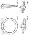
- Fig. 1 eine Ansicht der Vorrichtung mit Presshülse
- Fig. 2 eine Draufsicht auf die Vorrichtung
- Fig. 3 eine Seitenansicht der Vorrichtung
- Fig. 4 eine Ausführungsvariante mit mehreren Wendellagen
- Fig. 1 is a view of the device with a press sleeve
- Fig. 2 is a plan view of the device
- Fig. 3 is a side view of the device
- Fig. 4 shows a variant with several spiral layers
Ein konventionelles Stahldrahtseil 3 wird durch einen wendelförmigen Ring 1 hindurchgeschlauft. Somit verläuft die Rohrachse entlang einer schraubenförmigen Linie. Am Seil lässt sich ein Netz od.dgl. befestigen zur Aufnahme herabfallender Steine oder Schneemassen. Die Enden des Seiles 3 werden in üblicher Weise verankert. Die beiden Endbereiche 4 des einlagigen Wendels sind überlappend ausgeführt und verlaufen zueinander parallel und tangential zur Axe des Rohres 1. Auf die beiden Rohr-Endbereiche ist eine Presshülse 2 oder Seilklemme aufgesetzt, welche die Endbereiche des Rohres zusammenhalten. Der Durchmesser des Seiles 3 ist kleiner als der Rohr-Innendurchmesser, sodass sich das Seil leicht einziehen lässt. Die Presshülse bewirkt durch ihre Verpressung eine Deformierung der beiden Rohrenden die hernach flächig gegeneinander anliegen. Durch Wahl des Wendeldurchmessers und der Rohr-Wandstärke kann die Last-Dämpfungskurve in weiten Grenzen verändert und den jeweiligen Gegebenheiten angepasst werden.A conventional steel wire rope 3 is looped through a helical ring 1. The pipe axis thus runs along a helical line. A net or the like can be attached to the rope. attach to absorb falling stones or snow. The ends of the rope 3 are anchored in the usual way. The two end regions 4 of the single-layer helix are designed to overlap and run parallel to one another and tangential to the axis of the tube 1. A compression sleeve 2 or rope clamp is placed on the two tube end regions, which hold the end regions of the tube together. The diameter of the rope 3 is smaller than the inside diameter of the tube, so that the rope can be pulled in easily. The compression sleeve causes a deformation of the two pipe ends, which then lie flat against each other. By choosing the helix diameter and the tube wall thickness, the load-damping curve can be changed within wide limits and adapted to the respective circumstances.
Das Rohr wird vorzugsweise als handelsübliches geschweisstes Stahlrohr (Gasrohr) oder als nahtloses Stahlrohr ausgeführt mit einem Aussendurchmesser von 25-40 mm, einem Innendurchmesser von 20-30 mm, und einer gestreckten Länge von 1000-1500 mm.The pipe is preferably designed as a commercially welded steel pipe (gas pipe) or as a seamless steel pipe with an outer diameter of 25-40 mm, an inner diameter of 20-30 mm, and an elongated length of 1000-1500 mm.
Bei einer bevorzugten Ausführungsform haben sich folgende Abmessungen bewährt: Ein geschweisstes Stahlrohr (Gasrohr) feuerverzinkt, Aussendurchmesser 33,7, Wandstärke 3,25 mm, Radius der Ringaxe ca. 172 mm, Rohrlänge im ungebogenen Zustand ca. 1200 mm, und einer Kabellänge je nach Bedarf bis ca. 50 m.The following dimensions have proven themselves in a preferred embodiment: a welded steel pipe (gas pipe) hot-dip galvanized, outer diameter 33.7, wall thickness 3.25 mm, radius of the ring axis approx. 172 mm, pipe length in the unbent Condition approx. 1200 mm, and a cable length up to approx. 50 m depending on requirements.
Die Breite b der vorzugsweise aus einer Aluminiumlegierung bestehenden Presshülse 2 ist grösser als der Durchmesser des Rohres 1. Die beiden Rohrenden 4 überragen die Presshülse 2 auf gegenüberliegenden Seiten.The width b of the compression sleeve 2, which is preferably made of an aluminum alloy, is larger than the diameter of the tube 1. The two tube ends 4 protrude beyond the compression sleeve 2 on opposite sides.
Bei der Herstellung wird vorerst das Rohr 1 wendelförmig gebogen und die Presshülse 2 eingesetzt. Hernach wird das Stahldrahtseil 3 eingezogen. Durch unterschiedliche Verpressung der Presshülse oder Verspannung der Seilklemme kann die Lastgrenze verändert werden, bis eine Wendeldeformation und damit eine Seilverlängerung eintritt. Mit der Presshülse 2 können die beiden Rohrenden 4 so gegeneinander angepresst werden, dass zwischen diesen Rohrenden selbst und der Presshülse Reibschluss besteht.During manufacture, the tube 1 is initially bent in a helical shape and the compression sleeve 2 is inserted. The steel wire rope 3 is then drawn in. The load limit can be changed by different pressing of the compression sleeve or tensioning of the rope clamp until a spiral deformation and thus a rope extension occurs. With the press sleeve 2, the two pipe ends 4 can be pressed against one another in such a way that there is a frictional connection between these pipe ends themselves and the press sleeve.
Wenn auf das Seil eine Ueberlast einwirkt, bewirkt dies eine Verminderung des Wendeldurchmessers und eine Reibung des Rohrmantels am Pressring 2 und eine Rohrdeformierung. Der Durchmesser des Wendels wird vermindert, wobei das Rohr 1 mindestens auf einer Seite durch die Presshülse 2 hindurchgezogen wird. Durch diese plastische Materialdeformierung des Rohres 1 und die Reibung wird eine auf das Seil einwirkende Stossbelastung gedämpft und progressiv kinetische Energie abgebaut. Dadurch ist eine derartige Vorrichtung zum Auffangen herabstürzender Gesteins- oder Schneemassen geeignet, da die auf das Seil auftretende Belastung mit zunehmender Seilverlängerung progressiv abgebaut wird. Dabei kann die Seilfestigkeit voll ausgenützt werden. Bei relativ langen Seilen können mehrere derartige Wendel über die Seillänge verteilt angeordnet werden.If an overload acts on the rope, this causes a reduction in the helix diameter and a friction of the pipe jacket on the press ring 2 and a pipe deformation. The diameter of the helix is reduced, with the tube 1 being pulled through the compression sleeve 2 on at least one side. This plastic material deformation of the tube 1 and the friction dampens an impact load acting on the rope and progressively dissipates kinetic energy. As a result, such a device is suitable for collecting falling rock or snow masses, since the load on the rope is progressively reduced as the rope lengthens. The rope strength can be fully exploited. In the case of relatively long ropes, several such helices can be arranged distributed over the rope length.
In Figur 4 ist eine Ausführungsvariante dargestellt, bei der mehrere Wendellagen vorhanden sind. Die Presshülse 2 erstreckt sich dabei über alle Wendellagen. Gegebenenfalls könnten auch noch weitere Wendellagen vorgesehen werden.An embodiment variant is shown in FIG of which there are several spiral layers. The compression sleeve 2 extends over all spiral layers. If necessary, further spiral layers could also be provided.
Claims (6)
Priority Applications (1)
| Application Number | Priority Date | Filing Date | Title |
|---|---|---|---|
| AT91810923T ATE104407T1 (en) | 1990-12-31 | 1991-11-27 | SHOCK ABSORBING DEVICE FOR A TENSION ROPE FOR ROCKFALL AND SNOW DESTRUCTIONS. |
Applications Claiming Priority (2)
| Application Number | Priority Date | Filing Date | Title |
|---|---|---|---|
| CH4140/90 | 1990-12-31 | ||
| CH414090 | 1990-12-31 |
Publications (2)
| Publication Number | Publication Date |
|---|---|
| EP0494046A1 true EP0494046A1 (en) | 1992-07-08 |
| EP0494046B1 EP0494046B1 (en) | 1994-04-13 |
Family
ID=4270568
Family Applications (1)
| Application Number | Title | Priority Date | Filing Date |
|---|---|---|---|
| EP91810923A Expired - Lifetime EP0494046B1 (en) | 1990-12-31 | 1991-11-27 | Damping device for tensionable cable for retaining falling rocks or snowdrift |
Country Status (6)
| Country | Link |
|---|---|
| US (1) | US5207302A (en) |
| EP (1) | EP0494046B1 (en) |
| AT (1) | ATE104407T1 (en) |
| CA (1) | CA2058206C (en) |
| DE (1) | DE59101382D1 (en) |
| ES (1) | ES2053311T3 (en) |
Cited By (9)
| Publication number | Priority date | Publication date | Assignee | Title |
|---|---|---|---|---|
| EP1156158A1 (en) | 2000-05-18 | 2001-11-21 | Tecnap Sàrl | Shock absorbing device |
| EP1302595A1 (en) | 2001-10-09 | 2003-04-16 | AVT Anker + Vorspanntechnik AG | Brake element |
| EP1811087A2 (en) * | 2004-10-15 | 2007-07-25 | Malla Talud Cantabria, S.L. | Impact-absorbing device for use in earth-bank-protection systems |
| EP1870522A1 (en) * | 2006-06-17 | 2007-12-26 | Fatzer AG Drahtseilfabrik | Device for damping a rope under tension, in particular for protection against falling rocks, mudflows and avalanches |
| WO2009052950A1 (en) | 2007-10-18 | 2009-04-30 | Geobrugg Ag | Retarding device |
| WO2009153502A2 (en) * | 2008-06-18 | 2009-12-23 | Mnd Engineering | Power dissipator and dissipating stream |
| EP2650558A1 (en) | 2012-04-12 | 2013-10-16 | Geoprotection S.r.l. | Energy dissipation device for protecting structures or the like |
| EP3124700A1 (en) | 2015-07-29 | 2017-02-01 | 3S Geotecnia y Tecnologia S.L. | Energy dissipation device for protection systems |
| CN110295537A (en) * | 2019-07-02 | 2019-10-01 | 中冶南方工程技术有限公司 | A kind of bridge adds the base unit of sound barrier |
Families Citing this family (21)
| Publication number | Priority date | Publication date | Assignee | Title |
|---|---|---|---|---|
| KR100604179B1 (en) * | 1996-08-30 | 2006-12-07 | 파처 아게 | Protective device that prevents rockfall and absorbs high kinetic energy such as rockfall |
| US5961099A (en) * | 1998-01-23 | 1999-10-05 | Brugg Cable Products, Inc. | Safety net system for debris and mud slides |
| GB2341907B (en) | 1998-09-24 | 2002-02-13 | Notetry Ltd | Cable shock-absorbing device |
| US6131873A (en) * | 1998-12-30 | 2000-10-17 | Blazon; Fred R. | Energy absorbing high impact cable device |
| CH695104A5 (en) | 2000-11-13 | 2005-12-15 | Fatzer Ag | Safety net especially for rockfall barriers |
| KR100854138B1 (en) * | 2000-11-13 | 2008-08-26 | 파처 아게 | Catchment Net for Rockfall Catchment Systems or the Like |
| TW533256B (en) * | 2001-06-04 | 2003-05-21 | Yugen Kaisha Yoshida Kozo Deza | Shock absorbing fence and shock absorbing method thoerof |
| CH696469A5 (en) * | 2003-09-10 | 2007-06-29 | Fatzer Ag | Safety net, especially for rockfall barriers. |
| AU2004274835B2 (en) * | 2003-09-22 | 2010-09-16 | Australian Construction Products Pty Limited | Guardrail |
| US7104720B2 (en) * | 2003-11-19 | 2006-09-12 | Cyro Industries | Traffic noise barrier system |
| CH697096A5 (en) * | 2004-06-08 | 2008-04-30 | Fatzer Ag | Safety net, especially for rockfall protection or for verge securing. |
| CA2582552A1 (en) * | 2004-10-21 | 2006-05-04 | Igf Oncology, Llc | Toxins and radionuclides coupled to igf-1 receptor ligands for treatment of cancer |
| US6981673B1 (en) * | 2004-11-05 | 2006-01-03 | The United States Of America As Represented By The Secretary Of The Navy | Wear resisting sleeve system for aircraft landing arresting cables |
| NZ546970A (en) | 2006-05-04 | 2009-01-31 | Armorflex Ltd | Improvements in and relating to cable-barriers |
| US8596617B2 (en) | 2006-11-06 | 2013-12-03 | Axip Limited | Impact energy dissipation system |
| NZ555598A (en) * | 2007-06-01 | 2010-02-26 | Armorflex Ltd | Improved Barrier Section Connection System |
| NZ556782A (en) * | 2007-07-27 | 2010-03-26 | Armorflex Ltd | Method of producing a frangible post |
| US8424849B2 (en) * | 2008-06-04 | 2013-04-23 | Axip Limited | Guardrail |
| CH708244B1 (en) | 2013-06-28 | 2016-10-14 | Fatzer Ag | Wire rope as well as a method for producing the same. |
| US10767325B2 (en) | 2018-01-05 | 2020-09-08 | Superior Transparent Noise Barriers LLC | Impact absorbing traffic noise barrier system |
| US20240051441A1 (en) * | 2022-08-15 | 2024-02-15 | Ford Global Technologies, Llc | Energy absorbing device for vehicle seat |
Family Cites Families (5)
| Publication number | Priority date | Publication date | Assignee | Title |
|---|---|---|---|---|
| CA872446A (en) * | 1966-04-15 | 1971-06-01 | Slater Steel Industries Limited | Vibration dampers |
| GB1436702A (en) * | 1972-01-28 | 1976-05-26 | Nat Res Dev | Stress limiting or energy absorbing devices |
| CH610631A5 (en) * | 1975-09-08 | 1979-04-30 | Brugg Ag Kabelwerke | Mechanical connection which is loaded in tension, especially for shock absorption, having at least one wire cable and means for absorbing energy in the force transmission path |
| NO147538C (en) * | 1980-12-22 | 1983-04-27 | Standard Tel Kabelfab As | BOEYE RELIEF WITH VARIABLE STRENGTH. |
| IT1184798B (en) * | 1985-07-31 | 1987-10-28 | Gianangelo Cargnel | IMPROVED ELASTIC WALL PROTECTION STRUCTURE |
-
1991
- 1991-11-27 AT AT91810923T patent/ATE104407T1/en not_active IP Right Cessation
- 1991-11-27 ES ES91810923T patent/ES2053311T3/en not_active Expired - Lifetime
- 1991-11-27 DE DE59101382T patent/DE59101382D1/en not_active Expired - Lifetime
- 1991-11-27 EP EP91810923A patent/EP0494046B1/en not_active Expired - Lifetime
- 1991-12-16 US US07/807,986 patent/US5207302A/en not_active Expired - Lifetime
- 1991-12-20 CA CA002058206A patent/CA2058206C/en not_active Expired - Lifetime
Cited By (12)
| Publication number | Priority date | Publication date | Assignee | Title |
|---|---|---|---|---|
| EP1156158A1 (en) | 2000-05-18 | 2001-11-21 | Tecnap Sàrl | Shock absorbing device |
| EP1302595A1 (en) | 2001-10-09 | 2003-04-16 | AVT Anker + Vorspanntechnik AG | Brake element |
| EP1811087A2 (en) * | 2004-10-15 | 2007-07-25 | Malla Talud Cantabria, S.L. | Impact-absorbing device for use in earth-bank-protection systems |
| EP1811087A4 (en) * | 2004-10-15 | 2010-02-17 | Malla Talud Cantabria S L | Impact-absorbing device for use in earth-bank-protection systems |
| EP1870522A1 (en) * | 2006-06-17 | 2007-12-26 | Fatzer AG Drahtseilfabrik | Device for damping a rope under tension, in particular for protection against falling rocks, mudflows and avalanches |
| WO2009052950A1 (en) | 2007-10-18 | 2009-04-30 | Geobrugg Ag | Retarding device |
| WO2009153502A2 (en) * | 2008-06-18 | 2009-12-23 | Mnd Engineering | Power dissipator and dissipating stream |
| FR2932862A1 (en) * | 2008-06-18 | 2009-12-25 | Mnd Engineering | DISSIPATOR OF ENERGY AND DISSIPATING NET CORRESPONDING |
| WO2009153502A3 (en) * | 2008-06-18 | 2010-02-11 | Mnd Engineering | Power dissipator and dissipating stream |
| EP2650558A1 (en) | 2012-04-12 | 2013-10-16 | Geoprotection S.r.l. | Energy dissipation device for protecting structures or the like |
| EP3124700A1 (en) | 2015-07-29 | 2017-02-01 | 3S Geotecnia y Tecnologia S.L. | Energy dissipation device for protection systems |
| CN110295537A (en) * | 2019-07-02 | 2019-10-01 | 中冶南方工程技术有限公司 | A kind of bridge adds the base unit of sound barrier |
Also Published As
| Publication number | Publication date |
|---|---|
| CA2058206C (en) | 1999-02-02 |
| EP0494046B1 (en) | 1994-04-13 |
| CA2058206A1 (en) | 1992-07-01 |
| DE59101382D1 (en) | 1994-05-19 |
| ATE104407T1 (en) | 1994-04-15 |
| ES2053311T3 (en) | 1994-07-16 |
| US5207302A (en) | 1993-05-04 |
Similar Documents
| Publication | Publication Date | Title |
|---|---|---|
| EP0494046B1 (en) | Damping device for tensionable cable for retaining falling rocks or snowdrift | |
| EP1870522B1 (en) | Device for damping a rope under tension, in particular for protection against falling rocks, mudflows and avalanches | |
| EP2274535B1 (en) | Device for the impact damping of cable constructions, in particular for barrier structures for falling rock, mud flows and snow | |
| EP1795279A1 (en) | Protective net, in particular for protection against rock falls or for securing a top layer of soil | |
| JP6906100B2 (en) | Net and / or rope structure brake | |
| CH659503A5 (en) | METHOD FOR PRODUCING A BULB ON A STRING OF STEEL WIRE FOR ANCHORING IT IN COMPONENTS OF CONCRETE AND DEVICE FOR CARRYING OUT THIS METHOD. | |
| EP2427670B1 (en) | Device for absorbing kinetic energy of a moving body | |
| DE3104908A1 (en) | Spacer for the outer sheath (which is preferably constructed as a protective casing) of a heat and sound insulating layer on pipelines, boilers, facades or the like | |
| DE19707813A1 (en) | Device for connecting pipe parts | |
| EP1905943A2 (en) | Roller blind assembly | |
| DE3401260A1 (en) | Device for overload-shock absorption of cable structures | |
| DE2549280A1 (en) | SLEEVE O.DGL. FOR LONG ELEVATED BODIES | |
| DE4128768C2 (en) | Shock absorption device, in particular for a motor vehicle | |
| DE19520724A1 (en) | Rockfall etc safety barrier in rope design | |
| CH701591B1 (en) | Braking device. | |
| DE19944956C1 (en) | Device for attaching a vibration damper to an overhead line | |
| DE60030690T2 (en) | Shock-absorbing device | |
| DE4123390A1 (en) | HOLDING DEVICE FOR PIPELINES, ESPECIALLY FOR SUCH AS IN POWER PLANTS | |
| EP1469130A1 (en) | Braking element | |
| DE102006023313B4 (en) | gas spring | |
| AT524079A1 (en) | Device for bending pipes | |
| DE10356569B4 (en) | buckle unit | |
| DE102009038266A1 (en) | Spring i.e. coil spring, damper system, for use in hydraulic device, has damping element fastened to spring at connecting point such that plates, arranged at damping element shift motion of fluid during deformation of spring | |
| DE202008006330U1 (en) | Locker for a motor vehicle seatbelt with impact absorber | |
| EP1319754A1 (en) | Mesh screen panel with high deformation and energy absorbtion properties |
Legal Events
| Date | Code | Title | Description |
|---|---|---|---|
| PUAI | Public reference made under article 153(3) epc to a published international application that has entered the european phase |
Free format text: ORIGINAL CODE: 0009012 |
|
| AK | Designated contracting states |
Kind code of ref document: A1 Designated state(s): AT CH DE ES FR IT LI |
|
| 17P | Request for examination filed |
Effective date: 19920730 |
|
| 17Q | First examination report despatched |
Effective date: 19930927 |
|
| GRAA | (expected) grant |
Free format text: ORIGINAL CODE: 0009210 |
|
| AK | Designated contracting states |
Kind code of ref document: B1 Designated state(s): AT CH DE ES FR IT LI |
|
| REF | Corresponds to: |
Ref document number: 104407 Country of ref document: AT Date of ref document: 19940415 Kind code of ref document: T |
|
| REF | Corresponds to: |
Ref document number: 59101382 Country of ref document: DE Date of ref document: 19940519 |
|
| ET | Fr: translation filed | ||
| ITF | It: translation for a ep patent filed |
Owner name: MODIANO & ASSOCIATI S.R.L. |
|
| REG | Reference to a national code |
Ref country code: ES Ref legal event code: FG2A Ref document number: 2053311 Country of ref document: ES Kind code of ref document: T3 |
|
| PLBE | No opposition filed within time limit |
Free format text: ORIGINAL CODE: 0009261 |
|
| STAA | Information on the status of an ep patent application or granted ep patent |
Free format text: STATUS: NO OPPOSITION FILED WITHIN TIME LIMIT |
|
| 26N | No opposition filed | ||
| PGFP | Annual fee paid to national office [announced via postgrant information from national office to epo] |
Ref country code: DE Payment date: 20091128 Year of fee payment: 19 |
|
| PGFP | Annual fee paid to national office [announced via postgrant information from national office to epo] |
Ref country code: FR Payment date: 20091202 Year of fee payment: 19 |
|
| PGFP | Annual fee paid to national office [announced via postgrant information from national office to epo] |
Ref country code: AT Payment date: 20101115 Year of fee payment: 20 |
|
| PGFP | Annual fee paid to national office [announced via postgrant information from national office to epo] |
Ref country code: CH Payment date: 20101130 Year of fee payment: 20 |
|
| PGFP | Annual fee paid to national office [announced via postgrant information from national office to epo] |
Ref country code: IT Payment date: 20101126 Year of fee payment: 20 |
|
| PGFP | Annual fee paid to national office [announced via postgrant information from national office to epo] |
Ref country code: ES Payment date: 20101123 Year of fee payment: 20 |
|
| REG | Reference to a national code |
Ref country code: DE Ref legal event code: R119 Ref document number: 59101382 Country of ref document: DE Effective date: 20110601 Ref country code: DE Ref legal event code: R119 Ref document number: 59101382 Country of ref document: DE Effective date: 20110531 |
|
| REG | Reference to a national code |
Ref country code: FR Ref legal event code: ST Effective date: 20110801 |
|
| PG25 | Lapsed in a contracting state [announced via postgrant information from national office to epo] |
Ref country code: DE Free format text: LAPSE BECAUSE OF NON-PAYMENT OF DUE FEES Effective date: 20110531 |
|
| PG25 | Lapsed in a contracting state [announced via postgrant information from national office to epo] |
Ref country code: FR Free format text: LAPSE BECAUSE OF NON-PAYMENT OF DUE FEES Effective date: 20101130 |
|
| REG | Reference to a national code |
Ref country code: CH Ref legal event code: PL |
|
| REG | Reference to a national code |
Ref country code: AT Ref legal event code: MK07 Ref document number: 104407 Country of ref document: AT Kind code of ref document: T Effective date: 20111127 |
|
| REG | Reference to a national code |
Ref country code: ES Ref legal event code: FD2A Effective date: 20130730 |
|
| PG25 | Lapsed in a contracting state [announced via postgrant information from national office to epo] |
Ref country code: ES Free format text: LAPSE BECAUSE OF EXPIRATION OF PROTECTION Effective date: 20111128 |