EP0493977A2 - Molding machine - Google Patents
Molding machine Download PDFInfo
- Publication number
- EP0493977A2 EP0493977A2 EP91312076A EP91312076A EP0493977A2 EP 0493977 A2 EP0493977 A2 EP 0493977A2 EP 91312076 A EP91312076 A EP 91312076A EP 91312076 A EP91312076 A EP 91312076A EP 0493977 A2 EP0493977 A2 EP 0493977A2
- Authority
- EP
- European Patent Office
- Prior art keywords
- molding
- mold
- lower molding
- box
- boxes
- Prior art date
- Legal status (The legal status is an assumption and is not a legal conclusion. Google has not performed a legal analysis and makes no representation as to the accuracy of the status listed.)
- Withdrawn
Links
Images


Classifications
-
- B—PERFORMING OPERATIONS; TRANSPORTING
- B22—CASTING; POWDER METALLURGY
- B22C—FOUNDRY MOULDING
- B22C17/00—Moulding machines characterised by the mechanism for separating the pattern from the mould or for turning over the flask or the pattern plate
-
- B—PERFORMING OPERATIONS; TRANSPORTING
- B22—CASTING; POWDER METALLURGY
- B22C—FOUNDRY MOULDING
- B22C15/00—Moulding machines characterised by the compacting mechanism; Accessories therefor
- B22C15/28—Compacting by different means acting simultaneously or successively, e.g. preliminary blowing and finally pressing
Definitions
- the present invention relates to a molding machine and particularly to such an improved molding machine which comprises upper and lower molding boxes into which a molding sand is shot or injected under pressure so as to form a mold and then the mold is taken out.
- such a molding machine is constructed such that an upper molding box and a lower molding box are provided with a mchine body to be close and remote from each other in vertical directions and that a match plate having molding portions is provided between the upper and lower molding boxes to be movable in lateral directions.
- the above-mentioned sand shot is carried out by using a blowing opening formed with the side portion of each of the upper and lower molding boxes.
- the molding sand goes into the upper and lower molding boxes together with compressed air, only the compressed air is permitted to escape from the upper and lower boxes.
- a number of air escaping holes are formed with the inside wall of each of the upper and lower molding boxes.
- the molding sand with the compressed air shot into the upper and lower molding boxes is gradually accumulated on the match plate having molding portions.
- the molding sand shot into the upper molding box may be easily accumulated on the upper surface of the match plate due to its weight when the compressed air is escaped from the upper molding box. Since the compressed air cannot go through the match plate having the molding portions, the compressed air has to be escaped through the side wall of the lower molding box and a squeeze table located therebeneath. Accordingly, accumulation of the molding sand may be progressed on the side wall of the lower molding box and the squeeze table.
- an air curtain may be formed on the under surface of the match plate and therefore the molding sand cannot be easily accumulated on the under surface of the molding portions of the match plate and its accumulation cannot be precisely carried out.
- An object of this invention is to solve the above mentioned problems and to precisely form a mold in an upper and lower molding boxes with sand shot.
- the molding machine comprises an upper molding box movable in vertical directions and having a plurality of exhaust holes formed in the inside walls thereof, driving means for driving the upper molding box, a lower molding box movable in vertical directions with respect to the upper molding box, said lower molding box having a plurality of exhaust holes formed in all of the inside walls thereof, driving means for driving the lower molding box, a laterally movable match plate provided with molding portions and arranged to be clamped between the upper and lower molding boxes, shot means for introducing molding sand and compressed air into each of the upper and lower molding boxes from the side thereof, pressing means for punching out a mold in the upper and lower molding boxes, elevating means for lifting and lowering the mold in the upper and lower molding boxes, said elevating means being provided with a squeeze table for forming a bottom wall of the lower molding box and supporting the mold, said squeeze table being provided with a plurality of air blow holes arranged in a pattern of generally concentric circles, and auxiliary blow means for blowing air through the
- the molding sand shot into the lower molding box is blown upwardly by means of the air blown from the air blow holes of the squeeze table though it tends to fall down due to its weight.
- a seal made of resilient material such as rubber is provided around the sides of the squeeze table to be detachable in order to increase airtightness for the upper and lower molding boxes when the molding sand is shot under pressure.
- the seal tends to expand upward as connection between the seal and the squeeze table releases for a long term of use.
- the bottom surface of the mold engages with the seal rised from the squeeze table. Therefore, the mold does not slide smoothly on the squeeze table and sometimes it is broken. Further, rising of the seal reduces a sealing effect between the squeeze table and the lower molding box.
- the second object of the present invention is to smoothly push a mold on the squeeze table and to keep a sealing effect between the sides of the squeeze table and the lower molding box for a long time.
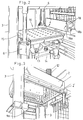
- Fig. 1 shows a molding machine body 1 and the machine body 1 is provided with an upper molding box 2 which is guided by means of a pair of guide poles 3, which are arranged diagonally, so as to be movable in vertical direction.
- 4 indicates an oil cylinder which comprises driving means for driving the upper molding box 2 in vertical directions.
- 5 is a lower molding box which is arranged to be movable in vertical directions with respect to the upper molding box 2.
- the lower molding box 5 is driven vertically by means of oil cylinders 6 as driving means therefor.
- the match plate 7 denotes a match plate having molding portions 7a and 7b, as shown in Figs. 4 and 7.
- the match plate 7 is driven by means of an air cylinder (not shown) as driving means to move in a sandwiched state between the upper and lower molding boxes 2 and 5 and move out of the sandwiched state in lateral directions.
- FIG. 9 shows shot means for shooting or injecting a molding sand into the upper and lower molding boxes 2 and 5 from the sides thereof with compressed air.
- the shot means comprises a blow head 9a, blow tank 8, a molding sand hopper 10 and an air compression means including an air compressor and a tank.
- the construction of the shot means belongs to a conventional art and therefore it is not described in detail herein.
- a number of air exhaust holes 2' and 5' are formed with the inside wall of each of the upper and lower molding boxes 2 and 5 for exhausting only air.
- the air shot from the blow head 9a together with the molding sand, is exhausted out of the upper and lower molding boxes 2 and 5 through the air exhaust holes 2' and 5'.
- the pressing means 11 denotes pressing means for pushing down or puching out a mold downwardly which is formed in the upper and lower molding boxes 2 and 5.
- the pressing means 11 mainly comprises the oil cylinder 4 and an upper plate 2a which forms an upper wall of the upper molding box 2. Therefore, the oil cylinder 4 is utilized for elevating the upper molding box 2 and puching out the mold.
- a compression spring 12 is interposed between the upper plate 2a and a part of the machine body 1 so as to always to press the upper plate 2a downwardly.
- the pressing means 11 per se is well known in the art oof this field and therefore it is not referred to in detail herein.
- the elevating means 13 is elevating means for lifting and lowering a mold formed in the upper and lower molding boxes 2 and 5.
- the elevating means 13 comprises mainly an oil cylinder 14 and a squeeze table 15 which is provided with an end of a rod of the oil cylinder 14 in order to form a bottom wall of the lower molding box 5 and support the mold and press same upwardly.
- auxiliary blow means 16 denotes auxiliary blow means for blowing air upwardly from the squeeze table 15 located beneath the lower molding box 5.
- the auxiliary blow means 16 will be described in detail with reference to Figs. 4 through 6.
- the squeeze table 15 comprises a table plate 15a and a table liner 15b which is arranged on the upper surface of the table plate 15a.
- An air passage R is formed between the table plate 15a and the table plate 15a and the table liner 15b and the air passage R is connected to an air pipe 15c which is connected to an air tank (not shown). Compressed air is accumulated in the air tank under predetermined pressure by means of an air compressor of the machine body 1.
- a number of air blow holes 16a are formed with the table liner 15b leaving a predetermined distance thereamong and each of the air blow holes 16a is communicated with the air passage R.
- Such blow holes 16a are arranged in a pattern of generally concentric circles as shown in Fig. 6.
- Air blow of the auxiliary blow means 16 is carried out simultaneously with the above mentioned sand shot.
- the air pressure blown by the auxiliary blow means is controlled preferably between 1.5 and 3.0 atmospheres.
- the operations of the auxiliary blow means 16, the upper and lower molding boxes 2 and 5 and molding steps may be controlled by automatic control means 17 which is provided with the machine body 1.
- the automatic control means 17 is such a type that it belongs to the conventional art in the field of automatic control system and does not include any novel technique and therefore it is not described in detail herein.
- the forward mechanism 18 shows a forwarding mechanism constructed to actuate in lateral direction so as to laterally transfer the mold after the mold is punched out from the upper and lower molding boxes 2 and 5.
- the forward mechanism 18 comprises a pushing plate 18a and an oil cylinder 18b for driving the pushing plate 18a.
- Fig. 8 is a vertical sectioinal view showing a part of the squeeze table 15 which is enlarged, and a seal 20 made of rubber is provided around the sides or periphery of the squeeze table 15.
- the rubber surface of the seal 20 on the side of the squeeze table 15 for sending the mold is lowered slightly from the upper surface of the table liner 15b of the squeeze table 15 so as to form a step.
- peeling force hardly acts on the upper surface of the seal 20 when the mold is pushed across the table liner 15b. Further, even if an end of the seal 20 is expands slightly as its attachment is released for a long time of use, the bottom surface of the mold would not engage with the seal 20.
- sealing may be maintained effectively between the seal 20 and the lower molding box 5 for a long time and it becomes possible to forward the mold smoothly.
- the match plate 7 having predetermined molding portions 7a and 7b, is moved laterally and positioned in a sandwiched state between the upper and lower molding boxes 2 and 5.
- a molding sand is shot into each of the upper and lower molding boxes 2 and 5 via the blow head 9a.
- compressed air is blown into the lower molding box 5 through the air blow holes 16a by means of the auxiliary blow means 16, and then the molding sand in the lower molding box 5 may flow and equivalently accumulate on the side of the match plate 7.
- the auxiliary blow means 16 it may easily obtain good accumulating conditions of the molding sand for the molding portions 7a of the under surface of the match plate 7. in the upper molding box 2, since the upper molding portions 7b is located in the falling direction of the molding sand due to its weight, fine accumulation of the molding sand may of course be obtained without any problem.
- the air blown from the blow head 9a is exhausted out through the exhausting holes 2' and 5' of the inside walls of the upper and lower molding boxes 2 and 5.
- the molding sand in the upper and lower molding boxes 2 and 5 is compressed strongly in vertical directions, and it is very effective to carry out air blow by means of the auxiliary blow means 16 in synchronism with a time overlapping the beginning of the compression step in order to increase fineness and precision of the mold.
- the upper and lower molding boxes 2 and 5 are moved away from each other in vertical directions with the match plate 7 as the central figure.
- the match plate 7 is moved laterally and removed from the sandwich state between the upper and lower molding boxes 2 and 5.
- a predetermined core 19 is set in the mold of the lower molding box 5.
- the upper and lower molding boxes 2 and 5 are moved to be in contact with each other and then the upper and lower molds are punched out downwardly from the upper and lower molding boxes 2 and 5 while supporting the molds by the squeeze table 15. Finally, as shown in Fig. 7h, the pushing plate 18a is forwarded by means of the oil cylinder 18b so as to laterally transfer the mold from the molding machine 1.
- the core 19 is used.
- the molding step of Fig. 7f may be omitted where the core 19 is not necessary.
Abstract
Description
- The present invention relates to a molding machine and particularly to such an improved molding machine which comprises upper and lower molding boxes into which a molding sand is shot or injected under pressure so as to form a mold and then the mold is taken out.
- Conventionally, such a molding machine is constructed such that an upper molding box and a lower molding box are provided with a mchine body to be close and remote from each other in vertical directions and that a match plate having molding portions is provided between the upper and lower molding boxes to be movable in lateral directions.
- After the match plate is clamped between the upper and lower molding boxes, molding sand is shot by compressed air into spaces formed by the match plate and the upper and lower molding boxes, and then the molding sand in the upper and lower molding boxes is squeezed in vertical directions to be hard. Then, the upper and lower molding boxes are moved away from each other in vertical directions and the match plate is taken out laterally and then the upper and lower boxes are moved close to each other again. Thereafter, the upper and lower molds formed in the upper and lower molding boxes are pushed down and then taken out from the machine body.
- The above-mentioned sand shot is carried out by using a blowing opening formed with the side portion of each of the upper and lower molding boxes. Although the molding sand goes into the upper and lower molding boxes together with compressed air, only the compressed air is permitted to escape from the upper and lower boxes. For the purpose, a number of air escaping holes are formed with the inside wall of each of the upper and lower molding boxes.
- However, in the above mentioned conventional art, the following problems arise in sand shot.
- Namely, the molding sand with the compressed air shot into the upper and lower molding boxes, is gradually accumulated on the match plate having molding portions. The molding sand shot into the upper molding box may be easily accumulated on the upper surface of the match plate due to its weight when the compressed air is escaped from the upper molding box. Since the compressed air cannot go through the match plate having the molding portions, the compressed air has to be escaped through the side wall of the lower molding box and a squeeze table located therebeneath. Accordingly, accumulation of the molding sand may be progressed on the side wall of the lower molding box and the squeeze table.
- However, an air curtain may be formed on the under surface of the match plate and therefore the molding sand cannot be easily accumulated on the under surface of the molding portions of the match plate and its accumulation cannot be precisely carried out.
- Further, since the compressed air is escaped from the lower molding box, the molding sand tends to fall with its weight. Therefore, it is every difficult to accumulate the molding sand on the under surface of the molding portions of the match plate. With the reasons, molding of the lower molding box could not be done well in the conventional machine.
- An object of this invention is to solve the above mentioned problems and to precisely form a mold in an upper and lower molding boxes with sand shot.
- To achieve the above mentioned object, the molding machine according to the present invention comprises an upper molding box movable in vertical directions and having a plurality of exhaust holes formed in the inside walls thereof, driving means for driving the upper molding box, a lower molding box movable in vertical directions with respect to the upper molding box, said lower molding box having a plurality of exhaust holes formed in all of the inside walls thereof, driving means for driving the lower molding box, a laterally movable match plate provided with molding portions and arranged to be clamped between the upper and lower molding boxes, shot means for introducing molding sand and compressed air into each of the upper and lower molding boxes from the side thereof, pressing means for punching out a mold in the upper and lower molding boxes, elevating means for lifting and lowering the mold in the upper and lower molding boxes, said elevating means being provided with a squeeze table for forming a bottom wall of the lower molding box and supporting the mold, said squeeze table being provided with a plurality of air blow holes arranged in a pattern of generally concentric circles, and auxiliary blow means for blowing air through the air blow holes of the squeeze table and only into the lower box as such squeeze table moves toward the match plate.
- Therefore, when sand shot is carried out while the match plate having the molding portions is sandwiched between the upper and lower molding boxes, the molding sand shot into the lower molding box is blown upwardly by means of the air blown from the air blow holes of the squeeze table though it tends to fall down due to its weight.
- As the molding sand flows into the lower molding box, sand accumulate evenly across and on the underside of the match plate.
- Accordingly, an air curtain is almost niver formed on the under surface of the molding portions of the match plate, which air curtain is formed in the conventional machine.
- As the result, it becomes possible to finely accumulate the molding sand on the under surface of the lower molding portions of the match plate so as to form a fine mold both in the upper and lower molding boxes even if the mold is grooved deeply.
- A seal made of resilient material such as rubber is provided around the sides of the squeeze table to be detachable in order to increase airtightness for the upper and lower molding boxes when the molding sand is shot under pressure. However, the seal tends to expand upward as connection between the seal and the squeeze table releases for a long term of use. As the result, when it is tried to push out the mold formed on the squeeze table, the bottom surface of the mold engages with the seal rised from the squeeze table. Therefore, the mold does not slide smoothly on the squeeze table and sometimes it is broken. Further, rising of the seal reduces a sealing effect between the squeeze table and the lower molding box.
- The second object of the present invention is to smoothly push a mold on the squeeze table and to keep a sealing effect between the sides of the squeeze table and the lower molding box for a long time.
- Other object and advantages of the present invention will be apparent from the description of the embodiment with reference to the drawings.
- The drawings show an embodiment of a molding machine according to the present invention in which:-
- Fig. 1 is a perspective view of the molding machine,
- Fig. 2 is a perspective view of an essential portion around a squeeze table,
- Fig. 3 is a perspective view of an upper molding box,
- Fig. 4 is a vertical sectional view of an essential portion thereof,
- Fig. 5 is a vertical sectional view of the squeeze table,
- Fig. 6 is a plan view of the squeeze table partly broken away,
- Fig. 7a through 7h are vertical sectional views showing molding steps,
- Fig. 8 is a vertical sectional view of the squeeze table partly enlarged.
- Fig. 1 shows a
molding machine body 1 and themachine body 1 is provided with anupper molding box 2 which is guided by means of a pair ofguide poles 3, which are arranged diagonally, so as to be movable in vertical direction. 4 indicates an oil cylinder which comprises driving means for driving theupper molding box 2 in vertical directions. - 5 is a lower molding box which is arranged to be movable in vertical directions with respect to the
upper molding box 2. - As shown in Fig. 2, the
lower molding box 5 is driven vertically by means ofoil cylinders 6 as driving means therefor. - 7 denotes a match plate having molding
portions match plate 7 is driven by means of an air cylinder (not shown) as driving means to move in a sandwiched state between the upper andlower molding boxes - 9 shows shot means for shooting or injecting a molding sand into the upper and
lower molding boxes - The shot means comprises a
blow head 9a,blow tank 8, amolding sand hopper 10 and an air compression means including an air compressor and a tank. The construction of the shot means belongs to a conventional art and therefore it is not described in detail herein. - A number of air exhaust holes 2' and 5' are formed with the inside wall of each of the upper and
lower molding boxes blow head 9a together with the molding sand, is exhausted out of the upper andlower molding boxes - 11 denotes pressing means for pushing down or puching out a mold downwardly which is formed in the upper and
lower molding boxes means 11 mainly comprises theoil cylinder 4 and anupper plate 2a which forms an upper wall of theupper molding box 2. Therefore, theoil cylinder 4 is utilized for elevating theupper molding box 2 and puching out the mold. - A
compression spring 12 is interposed between theupper plate 2a and a part of themachine body 1 so as to always to press theupper plate 2a downwardly. Thepressing means 11 per se is well known in the art oof this field and therefore it is not referred to in detail herein. - 13 is elevating means for lifting and lowering a mold formed in the upper and
lower molding boxes means 13 comprises mainly anoil cylinder 14 and a squeeze table 15 which is provided with an end of a rod of theoil cylinder 14 in order to form a bottom wall of thelower molding box 5 and support the mold and press same upwardly. - 16 denotes auxiliary blow means for blowing air upwardly from the squeeze table 15 located beneath the
lower molding box 5. The auxiliary blow means 16 will be described in detail with reference to Figs. 4 through 6. - The squeeze table 15 comprises a
table plate 15a and atable liner 15b which is arranged on the upper surface of thetable plate 15a. An air passage R is formed between thetable plate 15a and thetable plate 15a and thetable liner 15b and the air passage R is connected to anair pipe 15c which is connected to an air tank (not shown). Compressed air is accumulated in the air tank under predetermined pressure by means of an air compressor of themachine body 1. A number ofair blow holes 16a are formed with thetable liner 15b leaving a predetermined distance thereamong and each of theair blow holes 16a is communicated with the air passage R.Such blow holes 16a are arranged in a pattern of generally concentric circles as shown in Fig. 6. Air blow of the auxiliary blow means 16 is carried out simultaneously with the above mentioned sand shot. The air pressure blown by the auxiliary blow means is controlled preferably between 1.5 and 3.0 atmospheres. - The operations of the auxiliary blow means 16, the upper and
lower molding boxes machine body 1. The automatic control means 17 is such a type that it belongs to the conventional art in the field of automatic control system and does not include any novel technique and therefore it is not described in detail herein. - 18 shows a forwarding mechanism constructed to actuate in lateral direction so as to laterally transfer the mold after the mold is punched out from the upper and
lower molding boxes forward mechanism 18 comprises a pushingplate 18a and anoil cylinder 18b for driving the pushingplate 18a. - Fig. 8 is a vertical sectioinal view showing a part of the squeeze table 15 which is enlarged, and a
seal 20 made of rubber is provided around the sides or periphery of the squeeze table 15. - The rubber surface of the
seal 20 on the side of the squeeze table 15 for sending the mold, is lowered slightly from the upper surface of thetable liner 15b of the squeeze table 15 so as to form a step. With the step construction of theseal 20, peeling force hardly acts on the upper surface of theseal 20 when the mold is pushed across thetable liner 15b. Further, even if an end of theseal 20 is expands slightly as its attachment is released for a long time of use, the bottom surface of the mold would not engage with theseal 20. - Therefore, sealing may be maintained effectively between the
seal 20 and thelower molding box 5 for a long time and it becomes possible to forward the mold smoothly. - Next, molding steps will be described with reference to Figs. 7a and 7h.
- As shown in Fig. 7a, the
match plate 7 having predeterminedmolding portions lower molding boxes - Then, as shown in Fig. 7b, the upper and
lower molding boxes match plate 7. - As shown in Fig. 7c, a molding sand is shot into each of the upper and
lower molding boxes blow head 9a. At the same time, compressed air is blown into thelower molding box 5 through the air blow holes 16a by means of the auxiliary blow means 16, and then the molding sand in thelower molding box 5 may flow and equivalently accumulate on the side of thematch plate 7. With the function of the auxiliary blow means 16, it may easily obtain good accumulating conditions of the molding sand for themolding portions 7a of the under surface of thematch plate 7. in theupper molding box 2, since theupper molding portions 7b is located in the falling direction of the molding sand due to its weight, fine accumulation of the molding sand may of course be obtained without any problem. - The air blown from the
blow head 9a is exhausted out through the exhausting holes 2' and 5' of the inside walls of the upper andlower molding boxes - As shown in Fig. 7d, when sand shot is finished, the molding sand in the upper and
lower molding boxes lower molding boxes match plate 7 as the central figure. - As shown in Fig. 7e, the
match plate 7 is moved laterally and removed from the sandwich state between the upper andlower molding boxes - Next, as shown in Fig. 7f, a
predetermined core 19 is set in the mold of thelower molding box 5. - As shown in Fig. 7g, the upper and
lower molding boxes lower molding boxes plate 18a is forwarded by means of theoil cylinder 18b so as to laterally transfer the mold from themolding machine 1. - In the above mentioned molding steps, the
core 19 is used. However, the molding step of Fig. 7f may be omitted where thecore 19 is not necessary.
Claims (5)
- A molding machine comprising:
an upper molding box movable in vertical directions and having a plurality of exhaust holes formed in the inside walls thereof,
driving means for driving the upper molding box,
a lower molding box movable in vertical directions with respect to the upper molding box; said lower molding box having a plurality of exhaust holes formed in all of the inside walls thereof,
driving means for driving the lower molding box,
a laterally movable match plate provided with molding portions and arranged to be clamped between the upper and lower molding boxes,
shot means for introducing molding sand and compressed air into each of the upper and lower molding boxes from the side thereof,
pressing means for punching out a mold in the upper and lower molding boxes,
elevating means for lifting and lowering the mold in the upper and lower molding boxes; said elevating means being provided with a squeeze table for forming a bottom wall of the lower molding box and supporting the mold; said squeeze table being provided with a plurality of air blow holes arranged in a pattern of generally concentric circles, and
auxiliary blow means for blowing air through the air blow holes of the squeeze table and only into the lower box as such squeeze table moves toward the match plate. - The molding machine as claimed in claim 1 wherein the auxiliary blow means lncludes at least a table liner having air blow holes, a table plate and an air passage formed between the table liner and the table plate.
- The molding machine as claimed in claim 2 further comprising:
a seal around the periphery of the table liner of the squeeze table wherein the upper surface of that portion of the seal across which the mold is laterally transferred is lowered slightly from the upper surface of the table liner so as to form a step thereby preventing the mold from engaging the seal as the mold is laterally transferred from the machine. - A molding machine comprising:
an upper molding box movable in vetical directions and having a plurality of exhaust holes formed in the inside walls thereof,
a lower molding box movable in vertical directions with respect to the upper molding box; said lower molding box having a plurality of exhaust holes formed in all of the inside walls thereof,
driving means for driving the lower molding box,
a laterally movable match plate provided with molding portions and arranged to be clamped between the upper and lower molding boxes,
shot means for introducing molding sand and compressed air into each of the upper and lower molding boxes from the side thereof,
pressing means for punching out a mold in the upper and lower molding boxes,
elevating means for lifting and lowering the mold in the upper and lower molding boxes; said elevating means being provided with a squeeze table for forming a bottom wall of the lower molding box and supporting the mold; said squeeze table being provided with a plurality of air blow holes arranged in a pattern of generally concentric circles,
auxiliary blow means for blowing air through the air blow holes of the squeeze table and only into the lower box as the squeeze table moves toward the match plate; said auxiliary blow means including a table liner having air blow holes; a table plate and an air passage formed between the table liner and the table plate,
a seal around the periphery of the table liner of the squeeze table wherein the upper surface of that portion of the seal across which the mold is laterally transferred is lowered slightly from the upper surface of the table liner so as to form a step thereby preventing the mold from engaging the seal as the mold is laterally transferred from the machine. - The machine as claimed in claim 4 wherein that portion of the seal across which the mold is laterally transferred is generally triangular in shape.
Applications Claiming Priority (2)
| Application Number | Priority Date | Filing Date | Title |
|---|---|---|---|
| US636885 | 1984-08-02 | ||
| US07/636,885 US5125449A (en) | 1991-01-02 | 1991-01-02 | Improved molding machine |
Publications (2)
| Publication Number | Publication Date |
|---|---|
| EP0493977A2 true EP0493977A2 (en) | 1992-07-08 |
| EP0493977A3 EP0493977A3 (en) | 1993-05-26 |
Family
ID=24553747
Family Applications (1)
| Application Number | Title | Priority Date | Filing Date |
|---|---|---|---|
| EP19910312076 Withdrawn EP0493977A3 (en) | 1991-01-02 | 1991-12-30 | Molding machine |
Country Status (4)
| Country | Link |
|---|---|
| US (1) | US5125449A (en) |
| EP (1) | EP0493977A3 (en) |
| KR (1) | KR100196981B1 (en) |
| CN (1) | CN1031325C (en) |
Cited By (5)
| Publication number | Priority date | Publication date | Assignee | Title |
|---|---|---|---|---|
| WO2001070432A1 (en) * | 2000-03-20 | 2001-09-27 | Georg Fischer Disa A/S | Method and apparatus for producing two-part moulds |
| WO2001072450A1 (en) * | 2000-03-29 | 2001-10-04 | Georg Fischer Disa A/S | Moulding machine for producing flaskless moulds and methods for operating said machine |
| WO2002060616A1 (en) * | 2001-01-31 | 2002-08-08 | Disa Industries A/S | Method and machine for manufacturing sand moulds and down sprue assembly and holding plate to be used by the performance thereof |
| EP1741504A1 (en) * | 2004-04-28 | 2007-01-10 | Sintokogio, Ltd. | Method of squeezing foundry sand, match plate, and upper and lower flasks |
| WO2016198918A1 (en) * | 2015-06-12 | 2016-12-15 | Disa Industries A/S | Sand moulding machine and method of producing moulds |
Families Citing this family (11)
| Publication number | Priority date | Publication date | Assignee | Title |
|---|---|---|---|---|
| JP3226151B2 (en) * | 1995-12-15 | 2001-11-05 | 新東工業株式会社 | Blow squeeze mold making machine |
| WO2009098955A1 (en) * | 2008-02-04 | 2009-08-13 | Sintokogio, Ltd. | Core setter in mold making machine, mold making machine and method for setting core |
| CN101844207A (en) * | 2010-05-27 | 2010-09-29 | 南京化工职业技术学院 | Automatic steel ball casting forming machine |
| KR101232759B1 (en) * | 2012-11-19 | 2013-02-13 | (주)세원코리아 | Continuation automation manufacture device sand mold and manufacturing method |
| CN106735131A (en) * | 2016-12-05 | 2017-05-31 | 成都嘉新特种精密铸造有限公司 | A kind of efficient Casting Equipment of easy mold release |
| CN106735130A (en) * | 2016-12-05 | 2017-05-31 | 成都嘉新特种精密铸造有限公司 | A kind of new and effective casting device of easy mold release |
| CN106734971A (en) * | 2016-12-05 | 2017-05-31 | 成都嘉新特种精密铸造有限公司 | A kind of easy mold release high-efficiency environment friendly casting device |
| CN106694862A (en) * | 2016-12-05 | 2017-05-24 | 成都嘉新特种精密铸造有限公司 | Environment-friendly casting device capable of conducting demolding easily |
| CN106513645A (en) * | 2016-12-05 | 2017-03-22 | 成都嘉新特种精密铸造有限公司 | Novel casting equipment easy to demold |
| CN109834231B (en) * | 2019-04-18 | 2020-08-04 | 临沂天阔铸造有限公司 | Molding device for sand casting cavity |
| KR102250312B1 (en) | 2020-08-25 | 2021-05-10 | (주)코아이 | Landing net for seperating oil |
Citations (2)
| Publication number | Priority date | Publication date | Assignee | Title |
|---|---|---|---|---|
| GB2057319A (en) * | 1979-08-22 | 1981-04-01 | Sintokogio Ltd | Moulding machine |
| US4313486A (en) * | 1979-07-11 | 1982-02-02 | Kabushiki Kaisha Toyoda Jidoshokki Seisakusho | Sand mold-producing method and apparatus |
Family Cites Families (5)
| Publication number | Priority date | Publication date | Assignee | Title |
|---|---|---|---|---|
| JPS5645251A (en) * | 1979-09-18 | 1981-04-24 | Sintokogio Ltd | Molding method of drag |
| JPS5823180B2 (en) * | 1981-02-26 | 1983-05-13 | 株式会社 池田製作所 | Sand blowing device in automatic molding machine |
| SU975184A1 (en) * | 1981-05-26 | 1982-11-23 | Московский автомеханический институт | Method of producing single-use casting moulds |
| JPS6123552A (en) * | 1984-07-13 | 1986-02-01 | Sintokogio Ltd | Match plate mechanism |
| JPS6127145A (en) * | 1984-07-18 | 1986-02-06 | Taiyo Chuki Kk | High-packing molding method of drag mold in blow type automatic flaskless molding machine |
-
1991
- 1991-01-02 US US07/636,885 patent/US5125449A/en not_active Expired - Fee Related
- 1991-12-30 KR KR1019910025271A patent/KR100196981B1/en not_active IP Right Cessation
- 1991-12-30 EP EP19910312076 patent/EP0493977A3/en not_active Withdrawn
- 1991-12-31 CN CN91112608A patent/CN1031325C/en not_active Expired - Fee Related
Patent Citations (2)
| Publication number | Priority date | Publication date | Assignee | Title |
|---|---|---|---|---|
| US4313486A (en) * | 1979-07-11 | 1982-02-02 | Kabushiki Kaisha Toyoda Jidoshokki Seisakusho | Sand mold-producing method and apparatus |
| GB2057319A (en) * | 1979-08-22 | 1981-04-01 | Sintokogio Ltd | Moulding machine |
Cited By (10)
| Publication number | Priority date | Publication date | Assignee | Title |
|---|---|---|---|---|
| WO2001070432A1 (en) * | 2000-03-20 | 2001-09-27 | Georg Fischer Disa A/S | Method and apparatus for producing two-part moulds |
| WO2001072450A1 (en) * | 2000-03-29 | 2001-10-04 | Georg Fischer Disa A/S | Moulding machine for producing flaskless moulds and methods for operating said machine |
| WO2002060616A1 (en) * | 2001-01-31 | 2002-08-08 | Disa Industries A/S | Method and machine for manufacturing sand moulds and down sprue assembly and holding plate to be used by the performance thereof |
| EP1741504A1 (en) * | 2004-04-28 | 2007-01-10 | Sintokogio, Ltd. | Method of squeezing foundry sand, match plate, and upper and lower flasks |
| EP1741504A4 (en) * | 2004-04-28 | 2007-09-12 | Sintokogio Ltd | Method of squeezing foundry sand, match plate, and upper and lower flasks |
| KR100863104B1 (en) * | 2004-04-28 | 2008-10-13 | 신토고교 가부시키가이샤 | Method of squeezing foundry sand, match plate, and upper and lower flasks |
| US7448429B2 (en) | 2004-04-28 | 2008-11-11 | Sintokogio Ltd. | Method for squeezing foundry sand, a match plate, and an upper and a lower flask |
| CN1968770B (en) * | 2004-04-28 | 2010-12-22 | 新东工业株式会社 | Method of squeezing foundry sand, match plate, and double-sided template |
| WO2016198918A1 (en) * | 2015-06-12 | 2016-12-15 | Disa Industries A/S | Sand moulding machine and method of producing moulds |
| US10589347B2 (en) | 2015-06-12 | 2020-03-17 | Disa Industries A/S | Sand moulding machine and method of producing moulds |
Also Published As
| Publication number | Publication date |
|---|---|
| CN1064825A (en) | 1992-09-30 |
| KR100196981B1 (en) | 1999-06-15 |
| US5125449A (en) | 1992-06-30 |
| KR920014536A (en) | 1992-08-25 |
| CN1031325C (en) | 1996-03-20 |
| EP0493977A3 (en) | 1993-05-26 |
Similar Documents
| Publication | Publication Date | Title |
|---|---|---|
| EP0493977A2 (en) | Molding machine | |
| EP1149646B1 (en) | Molding device and molding method for sand mold | |
| US6345662B1 (en) | Automatic vibration molding machine for green sand mold | |
| US20020125593A1 (en) | Apparatus and method for molding blocks | |
| KR200436973Y1 (en) | Device for forming brick | |
| GB2131736A (en) | Brick-forming vacuum press | |
| JPH04365801A (en) | Press-forming device for spiral sintered parts | |
| US5695000A (en) | Apparatus for producing molds | |
| US4171720A (en) | Machine for producing foundry cores | |
| ITMI982079A1 (en) | DEVICE AND PROCEDURE FOR MAKING PRINTED PIECES | |
| JP3407879B2 (en) | Method and apparatus for filling and compressing molding sand | |
| EP0688592B1 (en) | Separating device | |
| US5148851A (en) | Method of charging sand and molding machine utilizing thereof | |
| US6604930B1 (en) | Concrete block molding machinery | |
| GB2107230A (en) | A moulding apparatus for making gas hardened sand mould | |
| CN1065789C (en) | Method of filling cores with molding sand | |
| JP3250189B2 (en) | Molding equipment for powder molding | |
| CA1047220A (en) | Core-shooting machine for preparing moulds and foundry cores | |
| EP1586441A1 (en) | Suction device for ceramic presses | |
| JPH0318077Y2 (en) | ||
| JP3173157B2 (en) | Powder molding equipment | |
| JPH0710829Y2 (en) | Compressed air blowing device in green molding equipment | |
| GB2230722A (en) | Venting pneumatically compressed sand, prior to mechanical sand compression | |
| US5261479A (en) | Molding machine with pattern venting | |
| KR100195812B1 (en) | Molding device for trim and flange of upper die |
Legal Events
| Date | Code | Title | Description |
|---|---|---|---|
| PUAI | Public reference made under article 153(3) epc to a published international application that has entered the european phase |
Free format text: ORIGINAL CODE: 0009012 |
|
| AK | Designated contracting states |
Kind code of ref document: A2 Designated state(s): AT CH DE ES FR GB IT LI |
|
| 17P | Request for examination filed |
Effective date: 19921125 |
|
| PUAL | Search report despatched |
Free format text: ORIGINAL CODE: 0009013 |
|
| AK | Designated contracting states |
Kind code of ref document: A3 Designated state(s): AT CH DE ES FR GB IT LI |
|
| 17Q | First examination report despatched |
Effective date: 19950808 |
|
| GRAG | Despatch of communication of intention to grant |
Free format text: ORIGINAL CODE: EPIDOS AGRA |
|
| GRAG | Despatch of communication of intention to grant |
Free format text: ORIGINAL CODE: EPIDOS AGRA |
|
| GRAH | Despatch of communication of intention to grant a patent |
Free format text: ORIGINAL CODE: EPIDOS IGRA |
|
| RAP1 | Party data changed (applicant data changed or rights of an application transferred) |
Owner name: TAIYO MACHINERY CO., LTD. |
|
| GRAH | Despatch of communication of intention to grant a patent |
Free format text: ORIGINAL CODE: EPIDOS IGRA |
|
| STAA | Information on the status of an ep patent application or granted ep patent |
Free format text: STATUS: THE APPLICATION HAS BEEN WITHDRAWN |
|
| 18W | Application withdrawn |
Withdrawal date: 19990401 |