EP0493704A1 - Electric motor - Google Patents
Electric motor Download PDFInfo
- Publication number
- EP0493704A1 EP0493704A1 EP91120978A EP91120978A EP0493704A1 EP 0493704 A1 EP0493704 A1 EP 0493704A1 EP 91120978 A EP91120978 A EP 91120978A EP 91120978 A EP91120978 A EP 91120978A EP 0493704 A1 EP0493704 A1 EP 0493704A1
- Authority
- EP
- European Patent Office
- Prior art keywords
- motor
- housing
- cooling
- cooling medium
- engine
- Prior art date
- Legal status (The legal status is an assumption and is not a legal conclusion. Google has not performed a legal analysis and makes no representation as to the accuracy of the status listed.)
- Granted
Links
Images

Classifications
-
- H—ELECTRICITY
- H02—GENERATION; CONVERSION OR DISTRIBUTION OF ELECTRIC POWER
- H02K—DYNAMO-ELECTRIC MACHINES
- H02K5/00—Casings; Enclosures; Supports
- H02K5/04—Casings or enclosures characterised by the shape, form or construction thereof
- H02K5/12—Casings or enclosures characterised by the shape, form or construction thereof specially adapted for operating in liquid or gas
- H02K5/132—Submersible electric motors
-
- H—ELECTRICITY
- H02—GENERATION; CONVERSION OR DISTRIBUTION OF ELECTRIC POWER
- H02K—DYNAMO-ELECTRIC MACHINES
- H02K5/00—Casings; Enclosures; Supports
- H02K5/04—Casings or enclosures characterised by the shape, form or construction thereof
- H02K5/20—Casings or enclosures characterised by the shape, form or construction thereof with channels or ducts for flow of cooling medium
- H02K5/203—Casings or enclosures characterised by the shape, form or construction thereof with channels or ducts for flow of cooling medium specially adapted for liquids, e.g. cooling jackets
Definitions
- the invention relates to an electric motor with a motor housing, in which a motor filling medium surrounding the motor is located, and with a pressure housing surrounding the motor housing, in which a housing filling medium is located.
- the electric drive i.e. the electric motor
- This waterproof encapsulated housing is designed so that it can withstand pressure at great depths of water.
- the watertight encapsulated housing pressure housing
- This filling medium surrounds the motor, which is filled with water or oil.
- the pressure of the motor filling medium is set to the pressure level of the housing filling medium surrounding the motor by means of a pressure compensation device attached to the motor.
- the pressure prevailing in the engine filling medium is therefore approximately the same as the pressure prevailing in the housing filling medium.
- a major disadvantage of the previously known engine is that the engine heat loss cannot be dissipated sufficiently via the filling medium surrounding the engine.
- An electric motor is known from EP 0 280 660 A2, which has a motor housing in which a stator and a rotor are arranged. There is a motor filling medium in the motor housing. A plurality of axially extending cooling channels are provided on the inner wall of the motor housing. However, there is no pressure housing surrounding the motor housing.
- the shaft carrying the rotor is designed as a hollow shaft that is open on one side. Holes are provided in the hollow shaft. The motor filling medium flows through the hollow shaft from its end in the axial direction to the holes. The engine filling medium then flows through the cooling channels in the opposite direction.
- a watertight encapsulated electrical machine in which water cooling channels are provided which surround the machine housing and which are formed by a cooling jacket which surrounds the cooling channels on all sides.
- the cooling jacket does not form part of the waterproof encapsulation of the electrical machine or the machine housing.
- the water cooling channels are not arranged on the inner wall of the pressure housing, but outside the pressure housing.
- DE 82 04 396 U1 discloses an electromotive drive consisting of a motor and a casing that tightly encapsulates the motor.
- a heat exchanger which can consist of a duct system, is arranged in the motor, specifically on or in the stator.
- a surrounding the motor housing Pressure housing is not available.
- the US 28 62 120 shows an electric motor with a double-walled, liquid-cooled housing, in which the inner jacket is eccentrically in the outer jacket.
- the inner jacket is held by axial baffles, which deflect the cooling water flow several times on its way around the housing from one end to the other.
- additional guide plates are arranged in the circumferential direction, which in turn deflect the axial flow several times.
- the object of the invention is to create an electric motor of the type specified at the outset, in which the accumulated heat loss can be dissipated sufficiently.
- the heat losses in the systems described above are dissipated in such a way that the engine does not overheat.
- this object is achieved by the combination of the features of claim 1.
- a heat exchanger consisting of at least one cooling channel is arranged, through which the engine filling medium flows as a cooling medium.
- the cooling medium is passed axially through the engine. The resulting heat loss can be transferred to the pressure housing wall via the heat exchanger and from there to the medium surrounding the pressure housing.
- the cooling channel preferably runs in a spiral over the length of the pressure housing.
- cooling medium is passed axially through the motor through the stator groove and / or the motor gap and / or through channels in the teeth and / or in the back of the laminated core.
- the cooling medium inlet opening on the one hand and the cooling medium outlet opening on the other hand can be located on the motor on opposite motor sides (AS and BS).
- the cooling medium flow can be forced by the engine itself or by a cooling circuit pump. If the motor itself acts as a coolant pump, this can be done by a whirl wheel placed on the motor shaft.
- the motor shaft for generating the cooling medium flow can be designed as a hollow shaft which has an axial cooling medium inlet opening on one side and a cooling medium outlet openings which are made radially on the other side. The hollow shaft is thus designed as a centrifugal pump.
- the cooling medium circulation is supported by natural convection if the coolant outlet is attached to the engine on the lower side of the engine housing.
- the heat exchanger or the cooling channel and, if appropriate, the inlet and outlet thereof are preferably thin-walled. This is made possible by the cooling medium is adjusted to the pressure in the pressure housing (pressure capsule housing) via the motor membrane. In the cooling medium on the one hand and in the housing filling medium on the other hand, the pressure is approximately the same.
- the cooling system it is possible to keep the internal engine pressure, unaffected by the cooling system, at the pressure level of the medium surrounding the motor housing (housing filling medium).
- the motor housing construction and the shaft seal of the drive remain unproblematic.
- the cooling concept can be integrated into the drive concept, so that only an extremely small additional technical effort is required.
- the invention further relates to a conveyor unit consisting of a motor according to the invention and a machine to be driven, in particular a pump.
- a conveyor unit consisting of a motor according to the invention and a machine to be driven, in particular a pump.
- An advantageous further development of such a delivery unit is characterized in that the motor and the machine to be driven are accommodated in a watertight encapsulated housing.
- a motor housing 2 in which a motor filling medium 6 surrounding the electric motor 11 is located, and a pressure housing 1 surrounding the motor housing 2, in which a housing filling medium 5 is located.
- a pressure compensation device 7 mounted on the electric motor 11
- the pressure of the Engine filling medium 6 is set to the pressure level of the housing filling medium 5 surrounding the electric motor 11.
- a heat exchanger is attached, which consists of a cooling channel 3, which runs spirally over the length of the cylindrical pressure housing 1. In the example shown, there are seven spiral turns.
- the motor filling medium 6 serves as the cooling medium flowing through the heat exchanger 3.
- the heat is given off in the cooling duct 3: heat conduction through the pressure housing wall 1 and heat transfer from the pressure housing wall 1 to the medium surrounding the pressure housing 1.
- the coolant inlet and outlet openings 8 on the engine are located opposite each other on the engine sides AS and BS.
- the coolant flow passes over the places where the heat is generated by being passed axially through the stator groove a, the motor gap b and through channels in the teeth c and in the back d of the laminated core through the electric motor 11.
- the coolant flow is forced by the engine itself or a cooling circuit pump. If the motor itself acts as a pump, this can either be accomplished by a whirl wheel placed on the shaft 9 or (or additionally) by a hollow shaft which has an axial coolant inlet opening on one side and a radially designed coolant outlet opening on the other side and is thus designed as a centrifugal pump.
- the coolant circulation is supported by natural convection if the coolant outlet on the engine is on the bottom Motor housing side is attached.
- the cooling channel 3 and its inlet and outlet 8 can be designed thin-walled 4, since the cooling medium is adjusted to the pressure in the pressure capsule housing via the motor membrane.
Abstract
Description
Die Erfindung betrifft einen Elektromotor mit einem Motorgehäuse, in dem sich ein den Motor umgebendes Motorfüllmedium befindet, und mit einem das Motorgehäuse umgebenden Druckgehäuse, in dem sich ein Gehäusefüllmedium befindet.The invention relates to an electric motor with a motor housing, in which a motor filling medium surrounding the motor is located, and with a pressure housing surrounding the motor housing, in which a housing filling medium is located.
Bei Antriebskonzepten für Anlagen unter Wasser, besonders in großen Wassertiefen, befindet sich der elektrische Antrieb, also der Elektromotor, zusammen mit der anzutreibenden Maschine in einem wasserdicht gekapselten Gehäuse. Dieses wasserdicht gekapselte Gehäuse ist so konzipiert, daß es auch dem Druck in großen Wassertiefen standhalten kann. Das wasserdicht gekapselte Gehäuse (Druckgehäuse) kann dabei je nach Antriebskonzept mit einem gasförmigen oder flüssigen Medium gefüllt sein. Dieses Füllmedium (Gehäusefüllmedium) umgibt den Motor, der wassergefüllt oder ölgefüllt ist. Über eine am Motor angebaute Druckausgleichsvorrichtung wird der Druck des Motorfüllmediums auf das Druckniveau des den Motor umgebenden Gehäusefüllmediums gesetzt. Der im Motorfüllmedium herrschende Druck ist also annähernd genauso groß wie der im Gehäusefüllmedium herrschende Druck.In the case of drive concepts for systems under water, especially at great water depths, the electric drive, i.e. the electric motor, is located in a waterproof, encapsulated housing together with the machine to be driven. This waterproof encapsulated housing is designed so that it can withstand pressure at great depths of water. The watertight encapsulated housing (pressure housing) can be filled with a gaseous or liquid medium depending on the drive concept. This filling medium (housing filling medium) surrounds the motor, which is filled with water or oil. The pressure of the motor filling medium is set to the pressure level of the housing filling medium surrounding the motor by means of a pressure compensation device attached to the motor. The pressure prevailing in the engine filling medium is therefore approximately the same as the pressure prevailing in the housing filling medium.
Ein Elektromotor der eingangs angegebenen Art ist aus der EP 0 297 274 A2 bekannt.An electric motor of the type specified at the outset is known from
Ein wesentlicher Nachteil bei dem vorbekannten Motor besteht darin, daß über das den Motor umgebende Füllmedium die Motorverlustwärme nicht ausreichend abgeführt werden kann.A major disadvantage of the previously known engine is that the engine heat loss cannot be dissipated sufficiently via the filling medium surrounding the engine.
Aus der EP 0 280 660 A2 ist ein Elektromotor bekannt, der ein Motorgehäuse besitzt, in dem ein Stator und ein Rotor angeordnet sind. In dem Motorgehäuse befindet sich ein Motorfüllmedium. An der Innenwandung des Motorgehäuses sind mehrere axial verlaufende Kühlkanäle vorgesehen. Ein das Motorgehäuse umgebendes Druckgehäuse ist allerdings nicht vorhanden. Die den Rotor tragende Welle ist als Hohlwelle ausgeführt, die an einer Seite offen ist. In der Hohlwelle sind Löcher vorgesehen. Das Motorfüllmedium durchströmt die Hohlwelle von ihrem Ende in axialer Richtung zu den Löchern. Das Motorfüllmedium durchströmt anschließend die Kühlkanäle in umgekehrter Richtung.An electric motor is known from
Aus der DE-PS 720 551 ist eine wasserdicht gekapselte elektrische Maschine bekannt, in der Wasserkühlkanäle vorgesehen sind, die das Maschinengehäuse umgeben und die durch einen Kühlmantel gebildet werden, der die Kühlkanäle allseitig umschließt. Der Kühlmantel bildet allerdings keinen Bestandteil der wasserdichten Kapselung der elektrischen Maschine oder des Maschinengehäuses. Die Wasserkühlkanäle sind nicht an der Innenwandung des Druckgehäuses angeordnet, sondern außerhalb des Druckgehäuses.From DE-PS 720 551 a watertight encapsulated electrical machine is known, in which water cooling channels are provided which surround the machine housing and which are formed by a cooling jacket which surrounds the cooling channels on all sides. However, the cooling jacket does not form part of the waterproof encapsulation of the electrical machine or the machine housing. The water cooling channels are not arranged on the inner wall of the pressure housing, but outside the pressure housing.
Die DE 82 04 396 U1 offenbart einen elektromotorischen Antrieb, bestehend aus einem Motor und einer den Motor dicht kapselnden Umhüllung. Im Motor, namentlich am oder im Ständer, ist ein Wärmetauscher angeordnet, der aus einem Kanalsystem bestehen kann. Ein das Motorgehäuse umgebendes Druckgehäuse ist nicht vorhanden.DE 82 04 396 U1 discloses an electromotive drive consisting of a motor and a casing that tightly encapsulates the motor. A heat exchanger, which can consist of a duct system, is arranged in the motor, specifically on or in the stator. A surrounding the motor housing Pressure housing is not available.
Aus der DE-OS 16 13 014 ist ein gekapselter Elektromotor mit Flüssigkeitskühlung bekannt, bei dem der als Gehäuse dienende Ständer schraubenförmige, eine Kühlflüssigkeit aufnehmende Kanäle aufweist. Die Kanäle sind als mindestens zweigängige, von einer mit dem Gehäuse dicht verbundenen Hülse überdeckte Gewindenuten ausgebildet. Auch hier ist ein das Motorgehäuse umgebendes Druckgehäuse nicht vorhanden.From DE-OS 16 13 014 an encapsulated electric motor with liquid cooling is known, in which the stand serving as the housing has screw-shaped channels that receive a coolant. The channels are designed as at least two-start thread grooves covered by a sleeve that is tightly connected to the housing. Here, too, there is no pressure housing surrounding the motor housing.
Die US 28 62 120 zeigt einen Elektromotor mit einem doppelwandigen, flüssigkeitsgekühlten Gehäuse, bei dem der Innenmantel exzentrisch im Außenmantel liegt. Der Innenmantel wird durch axiale Leitbleche gehalten, die den Kühlwasserstrom auf seinem Weg um das Gehäuse mehrmals von einer Stirnseite zur anderen umlenken. In den durch die Bleche gebildeten axialen Kanälen sind zusätzlich in Umfangsrichtung liegende Leitbleche angeordnet, die den Axialstrom wiederum mehrfach umlenken.The US 28 62 120 shows an electric motor with a double-walled, liquid-cooled housing, in which the inner jacket is eccentrically in the outer jacket. The inner jacket is held by axial baffles, which deflect the cooling water flow several times on its way around the housing from one end to the other. In the axial channels formed by the plates, additional guide plates are arranged in the circumferential direction, which in turn deflect the axial flow several times.
Hiervon ausgehend liegt der Erfindung die Aufgabe zugrunde, einen Elektromotor der eingangs angegebenen Art zu schaffen, bei dem die anfallende Verlustwärme ausreichend abgeführt werden kann. Insbesondere soll gewährleistet werden, daß in den oben beschriebenen Anlagen die anfallenden Wärmeverluste so abgeführt werden, daß der Motor sich nicht überhitzt.Proceeding from this, the object of the invention is to create an electric motor of the type specified at the outset, in which the accumulated heat loss can be dissipated sufficiently. In particular, it is to be ensured that the heat losses in the systems described above are dissipated in such a way that the engine does not overheat.
Erfindungsgemäß wird diese Aufgabe durch die Kombination der Merkmale des Anspruchs 1 gelöst. An der Innenwandung des Druckgehäuses ist ein aus mindestens einem Kühlkanal bestehender Wärmetauscher angeordnet, der von dem Motorfüllmedium als Kühlmedium durchströmt wird. Das Kühlmedium wird axial durch den Motor geleitet. Die anfallende Verlustwärme kann über den Wärmetauscher an die Druckgehäusewand abgegeben werden und von dort an das das Druckgehäuse umgebende Medium.According to the invention, this object is achieved by the combination of the features of claim 1. On the inner wall of the pressure housing, a heat exchanger consisting of at least one cooling channel is arranged, through which the engine filling medium flows as a cooling medium. The cooling medium is passed axially through the engine. The resulting heat loss can be transferred to the pressure housing wall via the heat exchanger and from there to the medium surrounding the pressure housing.
Vorteilhafte Weiterbildungen sind in den Unteransprüchen beschrieben.Advantageous further developments are described in the subclaims.
Vorzugsweise verläuft der Kühlkanal spiralförmig über die Länge des Druckgehäuses.The cooling channel preferably runs in a spiral over the length of the pressure housing.
Eine weitere vorteilhafte Weiterbildung ist dadurch gekennzeichnet, daß das Kühlmedium durch die Ständernut und/oder den Motorspalt und/oder durch Kanäle in den Zähnen und/oder im Rücken des Blechpakets axial durch den Motor geleitet wird.A further advantageous development is characterized in that the cooling medium is passed axially through the motor through the stator groove and / or the motor gap and / or through channels in the teeth and / or in the back of the laminated core.
Die Kühlmediumeinlaßöffnung einerseits und die Kühlmediumauslaßöffnung andererseits können sich am Motor auf entgegengesetzten Motorseiten (AS und BS) befinden.The cooling medium inlet opening on the one hand and the cooling medium outlet opening on the other hand can be located on the motor on opposite motor sides (AS and BS).
Der Kühlmediumstrom kann durch den Motor selbst oder durch eine Kühlkreislaufpumpe erzwungen werden. Sofern der Motor selbst als Kühlmediumpumpe fungiert, kann dies durch ein auf die Motorwelle gesetztes Quirlrad bewerkstelligt werden. Statt dessen oder zusätzlich kann die Motorwelle zur Erzeugung des Kühlmediumstroms als Hohlwelle ausgebildet sein, die auf der einen Seite über eine axiale Kühlmediumeinlaßöffnung und auf der anderen Seite über radial ausgeführte Kühlmediumauslaßöffnungen verfügt. Die Hohlwelle ist somit als Zentrifugalpumpe ausgebildet.The cooling medium flow can be forced by the engine itself or by a cooling circuit pump. If the motor itself acts as a coolant pump, this can be done by a whirl wheel placed on the motor shaft. Instead or in addition, the motor shaft for generating the cooling medium flow can be designed as a hollow shaft which has an axial cooling medium inlet opening on one side and a cooling medium outlet openings which are made radially on the other side. The hollow shaft is thus designed as a centrifugal pump.
Bei vertikaler Motoranordnung wird die Kühlmediumumwälzung durch die natürliche Konvektion unterstützt, wenn der Kühlmittelaustritt am Motor auf der unten liegenden Motorgehäuseseite angebracht ist.In the case of a vertical engine arrangement, the cooling medium circulation is supported by natural convection if the coolant outlet is attached to the engine on the lower side of the engine housing.
Vorzugsweise sind der Wärmetauscher bzw. der Kühlkanal und gegebenenfalls dessen Zu- und Ableitung dünnwandig ausgebildet. Dies wird dadurch ermöglicht, daß das Kühlmedium über die Motormembran dem Druck im Druckgehäuse (Druckkapselgehäuse) angeglichen wird. Im Kühlmedium einerseits und im Gehäusefüllmedium andererseits herrscht also annähernd derselbe Druck.The heat exchanger or the cooling channel and, if appropriate, the inlet and outlet thereof are preferably thin-walled. This is made possible by the cooling medium is adjusted to the pressure in the pressure housing (pressure capsule housing) via the motor membrane. In the cooling medium on the one hand and in the housing filling medium on the other hand, the pressure is approximately the same.
Nach der Erfindung ist es möglich, den Motorinnendruck, unbeeinflußt durch das Kühlsystem, auf dem Druckniveau des das Motorgehäuse umgebenden Mediums (Gehäusefüllmedium) zu halten. Die Motorgehäusekonstruktion und die Wellenabdichtung des Antriebs bleiben somit unproblematisch. Das Kühlkonzept kann in das Antriebskonzept integriert werden, so daß nur ein äußerst geringer technischer Zusatzaufwand erforderlich ist.According to the invention, it is possible to keep the internal engine pressure, unaffected by the cooling system, at the pressure level of the medium surrounding the motor housing (housing filling medium). The motor housing construction and the shaft seal of the drive remain unproblematic. The cooling concept can be integrated into the drive concept, so that only an extremely small additional technical effort is required.
Die Erfindung betrifft weiterhin ein Förderaggregat, bestehend aus einem erfindungsgemäßen Motor und einer anzutreibenden Maschine, insbesondere einer Pumpe. Eine vorteilhafte Weiterbildung eines derartigen Förderaggregats ist dadurch gekennzeichnet, daß der Motor und die anzutreibende Maschine in einem wasserdicht gekapselten Gehäuse untergebracht sind.The invention further relates to a conveyor unit consisting of a motor according to the invention and a machine to be driven, in particular a pump. An advantageous further development of such a delivery unit is characterized in that the motor and the machine to be driven are accommodated in a watertight encapsulated housing.
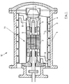
Ein Ausführungsbeispiel der Erfindung wird nachstehend anhand der beigefügten Zeichnung im einzelnen erläutert. In der Zeichnung zeigt
- Fig. 1:
- einen Motor im Längsschnitt und
- Fig. 2:
- einen Teilquerschnitt durch den Motor gem. Fig. 1.
- Fig. 1:
- a motor in longitudinal section and
- Fig. 2:
- a partial cross section through the engine acc. Fig. 1.
Der in der Fig. 1 insgesamt mit 10 bezeichnete Motor besteht aus einem Motorgehäuse 2, in dem sich ein den Elektromotor 11 umgebendes Motorfüllmedium 6 befindet, und einem das Motorgehäuse 2 umgebenden Druckgehäuse 1, in dem sich ein Gehäusefüllmedium 5 befindet. Über eine am Elektromotor 11 angebaute Druckausgleichsvorrichtung 7 wird der Druck des Motorfüllmediums 6 auf das Druckniveau des den Elektromotor 11 umgebenden Gehäusefüllmediums 5 gesetzt. An der Innenwandung des den Elektromotor 11 umgebenden Druckgehäuses 1 ist ein Wärmetauscher angebracht, der aus einem Kühlkanal 3 besteht, der über die Länge des zylinderförmigen Druckgehäuses 1 spiralförmig verläuft. Im dargestellten Beispiel sind sieben Spiralwindungen vorhanden. Als den Wärmetauscher 3 durchströmendes Kühlmedium dient das Motorfüllmedium 6. Es wird vom Elektromotor 11 über eine Zuleitung 8 in den spiralförmigen Kühlkanal 3 eingeleitet und am anderen Ende des spiralförmigen Kühlkanals 3 über eine Ableitung 8 wieder dem Elektromotor 11 zugeführt. Die Wärmeabgabe erfolgt im Kühlkanal 3: Wärmeleitung durch die Druckgehäusewand 1 und Wärmeübergang von der Druckgehäusewand 1 an das das Druckgehäuse 1 umgebende Medium. Die Kühlmitteleinlaß- und Auslaßöffnungen 8 am Motor befinden sich jeweils entgegengesetzt auf den Motorseiten AS und BS.1 consists of a
Wie aus Fig. 2 ersichtlich, überstreicht der Kühlmittelfluß die Entstehungsorte der Wärme, indem er durch die Ständernut a, den Motorspalt b und durch Kanäle in den Zähnen c und im Rücken d des Blechpakets axial durch den Elektromotor 11 geleitet wird.As can be seen from FIG. 2, the coolant flow passes over the places where the heat is generated by being passed axially through the stator groove a, the motor gap b and through channels in the teeth c and in the back d of the laminated core through the
Der Kühlmittelstrom wird durch den Motor selbst oder eine Kühlkreislaufpumpe erzwungen. Sofern der Motor selbst als Pumpe fungiert, kann dies entweder durch ein auf die Welle 9 gesetztes Quirlrad bewerkstelltigt werden oder (bzw. zusätzlich) durch eine Hohlwelle, die auf der einen Seite über eine axiale Kühlmitteleinlaßöffnung und auf der anderen Seite über radial ausgeführte Kühlmittelauslaßöffnungen verfügt und somit als Zentrifugalpumpe ausgebildet ist.The coolant flow is forced by the engine itself or a cooling circuit pump. If the motor itself acts as a pump, this can either be accomplished by a whirl wheel placed on the
Bei vertikaler Motoranordnung wird die Kühlmittelumwälzung durch die natürliche Konvektion unterstützt, wenn der Kühlmittelaustritt am Motor auf der unten liegenden Motorgehäuseseite angebracht ist.In the case of a vertical engine arrangement, the coolant circulation is supported by natural convection if the coolant outlet on the engine is on the bottom Motor housing side is attached.
Der Kühlkanal 3 sowie dessen Zu- und Ableitung 8 können dünnwandig 4 konzipiert werden, da das Kühlmedium über die Motormembran dem Druck im Druckkapselgehäuse angeglichen wird.The cooling
Claims (12)
einem Motorgehäuse (2), in dem sich ein den Motor (11) umgebendes Motorfüllmedium (6) befindet,
und einem das Motorgehäuse (2) umgebenden Druckgehäuse (1), in dem sich ein Gehäusefüllmedium (5) befindet,
wobei an der Innenwandung (1) des Druckgehäuses ein aus mindestens einem Kühlkanal (3) bestehender Wärmetauscher angeordnet ist, der von dem Motorfüllmedium (6) als Kühlmedium durchströmt wird
und wobei das Kühlmedium axial durch den Motor (11) geleitet wird.Electric motor with
a motor housing (2) in which a motor filling medium (6) surrounding the motor (11) is located,
and a pressure housing (1) surrounding the motor housing (2) and containing a housing filling medium (5),
A heat exchanger consisting of at least one cooling channel (3) is arranged on the inner wall (1) of the pressure housing and flows through the engine filling medium (6) as the cooling medium
and wherein the cooling medium is passed axially through the motor (11).
Applications Claiming Priority (2)
| Application Number | Priority Date | Filing Date | Title |
|---|---|---|---|
| DE4100135A DE4100135C1 (en) | 1991-01-04 | 1991-01-04 | |
| DE4100135 | 1991-01-04 |
Publications (2)
| Publication Number | Publication Date |
|---|---|
| EP0493704A1 true EP0493704A1 (en) | 1992-07-08 |
| EP0493704B1 EP0493704B1 (en) | 1995-04-05 |
Family
ID=6422565
Family Applications (1)
| Application Number | Title | Priority Date | Filing Date |
|---|---|---|---|
| EP91120978A Expired - Lifetime EP0493704B1 (en) | 1991-01-04 | 1991-12-06 | Electric motor |
Country Status (3)
| Country | Link |
|---|---|
| EP (1) | EP0493704B1 (en) |
| DE (2) | DE4100135C1 (en) |
| NO (1) | NO304089B1 (en) |
Cited By (7)
| Publication number | Priority date | Publication date | Assignee | Title |
|---|---|---|---|---|
| WO1997045914A1 (en) * | 1996-05-29 | 1997-12-04 | Asea Brown Boveri Ab | Rotary electric machine with axial cooling |
| WO1997048167A1 (en) * | 1996-06-13 | 1997-12-18 | Ksb Aktiengesellschaft | Liquid-filled underwater motor |
| WO1999005024A1 (en) * | 1997-07-21 | 1999-02-04 | Siemens Aktiengesellschaft | Electromotive gondola or ship drive system with cooling device |
| GB2342713A (en) * | 1996-09-26 | 2000-04-19 | Alstom Uk Ltd | Power equipment for use underwater |
| WO2001063725A1 (en) * | 2000-02-25 | 2001-08-30 | Voith Siemens Hydro Power Generation Gmbh & Co. Kg | High-voltage electric rotary machine and a method for cooling the conductors of said machine |
| EP1300924A2 (en) * | 2001-10-03 | 2003-04-09 | Nissan Motor Co., Ltd. | Rotating electric machine and cooling structure for rotating electric machine |
| DE102006049326A1 (en) * | 2006-10-19 | 2008-04-30 | Siemens Ag | Encapsulated electric machine with liquid-cooled stator |
Families Citing this family (23)
| Publication number | Priority date | Publication date | Assignee | Title |
|---|---|---|---|---|
| DE4209118C2 (en) * | 1991-12-23 | 1993-12-09 | Loher Ag | Asynchronous motor |
| DE4244644C2 (en) * | 1991-12-23 | 1994-12-22 | Loher Ag | Electric motor |
| JP2000515357A (en) | 1996-05-29 | 2000-11-14 | アセア、ブラウン、ボベリ、アクチエボラーグ | Rotary electric plant |
| SE9602079D0 (en) | 1996-05-29 | 1996-05-29 | Asea Brown Boveri | Rotating electric machines with magnetic circuit for high voltage and a method for manufacturing the same |
| WO1997045918A1 (en) | 1996-05-29 | 1997-12-04 | Asea Brown Boveri Ab | Insulated conductor for high-voltage windings and a method of manufacturing the same |
| SE510192C2 (en) | 1996-05-29 | 1999-04-26 | Asea Brown Boveri | Procedure and switching arrangements to reduce problems with three-tier currents that may occur in alternator and motor operation of AC machines connected to three-phase distribution or transmission networks |
| AU2989197A (en) | 1996-05-29 | 1998-01-05 | Asea Brown Boveri Ab | Conductor for high-voltage windings and a rotating electric machine comprising a winding including the conductor |
| SE509072C2 (en) | 1996-11-04 | 1998-11-30 | Asea Brown Boveri | Anode, anodizing process, anodized wire and use of such wire in an electrical device |
| SE515843C2 (en) | 1996-11-04 | 2001-10-15 | Abb Ab | Axial cooling of rotor |
| SE510422C2 (en) | 1996-11-04 | 1999-05-25 | Asea Brown Boveri | Magnetic sheet metal core for electric machines |
| SE512917C2 (en) | 1996-11-04 | 2000-06-05 | Abb Ab | Method, apparatus and cable guide for winding an electric machine |
| SE9704423D0 (en) | 1997-02-03 | 1997-11-28 | Asea Brown Boveri | Rotary electric machine with flushing support |
| SE9704431D0 (en) | 1997-02-03 | 1997-11-28 | Asea Brown Boveri | Power control of synchronous machine |
| SE508543C2 (en) | 1997-02-03 | 1998-10-12 | Asea Brown Boveri | Coiling |
| SE9704427D0 (en) | 1997-02-03 | 1997-11-28 | Asea Brown Boveri | Fastening device for electric rotary machines |
| SE508544C2 (en) | 1997-02-03 | 1998-10-12 | Asea Brown Boveri | Method and apparatus for mounting a stator winding consisting of a cable. |
| SE9704421D0 (en) | 1997-02-03 | 1997-11-28 | Asea Brown Boveri | Series compensation of electric alternator |
| SE9704422D0 (en) | 1997-02-03 | 1997-11-28 | Asea Brown Boveri | End plate |
| GB2331867A (en) | 1997-11-28 | 1999-06-02 | Asea Brown Boveri | Power cable termination |
| EP1042853A2 (en) | 1997-11-28 | 2000-10-11 | Abb Ab | Method and device for controlling the magnetic flux with an auxiliary winding in a rotating high voltage electric alternating current machine |
| US6801421B1 (en) | 1998-09-29 | 2004-10-05 | Abb Ab | Switchable flux control for high power static electromagnetic devices |
| NO325341B1 (en) * | 2005-12-05 | 2008-03-31 | Norsk Hydro Produksjon As | Dressing system for an electric motor, and a drive system for operating a impeller |
| DE102021206772A1 (en) | 2021-06-29 | 2022-12-29 | Scanlab Gmbh | Galvanometer drive with improved stator geometry |
Citations (5)
| Publication number | Priority date | Publication date | Assignee | Title |
|---|---|---|---|---|
| DE509174C (en) * | 1927-04-26 | 1930-10-04 | Wilhelm Jakob Hoffmann | Air cooling device on an electrical machine used for operation under water with a vertical shaft, which is arranged within a protective jacket with a hood attached |
| FR1022783A (en) * | 1950-08-03 | 1953-03-10 | Alsthom Cgee | Improvements in cooling of closed electrical machines |
| DE1149448B (en) * | 1961-05-04 | 1963-05-30 | Ritz Motorenbau K G | Underwater electric motor filled with a cooling medium with an attached heat exchanger |
| FR1422506A (en) * | 1965-01-15 | 1965-12-24 | Bbc Brown Boveri & Cie | Device for cooling an alternator for bulb group |
| EP0280660A2 (en) * | 1987-02-17 | 1988-08-31 | Ekochemie S.R.L. | Immersed electric motor to operate pumps and the like |
Family Cites Families (7)
| Publication number | Priority date | Publication date | Assignee | Title |
|---|---|---|---|---|
| DE516474C (en) * | 1926-11-13 | 1931-01-23 | Siemens Schuckertwerke Akt Ges | Waterproof encapsulated electrical machine with pronounced pole poles |
| DE720551C (en) * | 1937-11-04 | 1942-05-08 | Lloyd Dynamowerke Ag | Waterproof enclosed electrical machine |
| US2862120A (en) * | 1957-07-02 | 1958-11-25 | Onsrud Machine Works Inc | Fluid-cooled motor housing |
| DE1930080U (en) * | 1964-04-21 | 1965-12-30 | Friedrich Wilhelm Pleuger | EXPLOSION-PROOF ELECTRIC MOTOR. |
| DE1613014A1 (en) * | 1967-07-05 | 1970-09-17 | Messerschmitt Boelkow Blohm | Encapsulated electric motor with liquid cooling |
| DE8204396U1 (en) * | 1982-02-17 | 1983-09-22 | Stelzer, Erwin, Ing.(Grad.), 3530 Warburg | DRIVE DEVICE |
| DE3721398A1 (en) * | 1987-06-29 | 1989-01-19 | Bornemann J H Gmbh & Co | CONVEYOR UNIT CONSISTING OF A PUMP WITH A DRIVE DEVICE |
-
1991
- 1991-01-04 DE DE4100135A patent/DE4100135C1/de not_active Expired - Fee Related
- 1991-12-06 DE DE59105116T patent/DE59105116D1/en not_active Expired - Fee Related
- 1991-12-06 EP EP91120978A patent/EP0493704B1/en not_active Expired - Lifetime
- 1991-12-20 NO NO915061A patent/NO304089B1/en not_active IP Right Cessation
Patent Citations (5)
| Publication number | Priority date | Publication date | Assignee | Title |
|---|---|---|---|---|
| DE509174C (en) * | 1927-04-26 | 1930-10-04 | Wilhelm Jakob Hoffmann | Air cooling device on an electrical machine used for operation under water with a vertical shaft, which is arranged within a protective jacket with a hood attached |
| FR1022783A (en) * | 1950-08-03 | 1953-03-10 | Alsthom Cgee | Improvements in cooling of closed electrical machines |
| DE1149448B (en) * | 1961-05-04 | 1963-05-30 | Ritz Motorenbau K G | Underwater electric motor filled with a cooling medium with an attached heat exchanger |
| FR1422506A (en) * | 1965-01-15 | 1965-12-24 | Bbc Brown Boveri & Cie | Device for cooling an alternator for bulb group |
| EP0280660A2 (en) * | 1987-02-17 | 1988-08-31 | Ekochemie S.R.L. | Immersed electric motor to operate pumps and the like |
Cited By (12)
| Publication number | Priority date | Publication date | Assignee | Title |
|---|---|---|---|---|
| WO1997045914A1 (en) * | 1996-05-29 | 1997-12-04 | Asea Brown Boveri Ab | Rotary electric machine with axial cooling |
| WO1997048167A1 (en) * | 1996-06-13 | 1997-12-18 | Ksb Aktiengesellschaft | Liquid-filled underwater motor |
| GB2342713A (en) * | 1996-09-26 | 2000-04-19 | Alstom Uk Ltd | Power equipment for use underwater |
| GB2342713B (en) * | 1996-09-26 | 2000-10-25 | Alstom Uk Ltd | Power equipment for use underwater |
| US6145584A (en) * | 1996-09-26 | 2000-11-14 | Alstom Uk Ltd. | Power equipment for use underwater |
| WO1999005024A1 (en) * | 1997-07-21 | 1999-02-04 | Siemens Aktiengesellschaft | Electromotive gondola or ship drive system with cooling device |
| US6312298B1 (en) | 1997-07-21 | 2001-11-06 | Siemens Aktiengesellschaft | Electromotive drive system for a ship |
| WO2001063725A1 (en) * | 2000-02-25 | 2001-08-30 | Voith Siemens Hydro Power Generation Gmbh & Co. Kg | High-voltage electric rotary machine and a method for cooling the conductors of said machine |
| US6825584B2 (en) | 2000-02-25 | 2004-11-30 | Voith Siemens Hydro Power Generation Gmbh & Co. Kg | High-voltage electric rotary machine and a method for cooling the conductors of said machine |
| EP1300924A2 (en) * | 2001-10-03 | 2003-04-09 | Nissan Motor Co., Ltd. | Rotating electric machine and cooling structure for rotating electric machine |
| EP1300924A3 (en) * | 2001-10-03 | 2005-07-27 | Nissan Motor Co., Ltd. | Rotating electric machine and cooling structure for rotating electric machine |
| DE102006049326A1 (en) * | 2006-10-19 | 2008-04-30 | Siemens Ag | Encapsulated electric machine with liquid-cooled stator |
Also Published As
| Publication number | Publication date |
|---|---|
| DE59105116D1 (en) | 1995-05-11 |
| NO915061D0 (en) | 1991-12-20 |
| NO304089B1 (en) | 1998-10-19 |
| EP0493704B1 (en) | 1995-04-05 |
| DE4100135C1 (en) | 1992-05-14 |
| NO915061L (en) | 1992-07-06 |
Similar Documents
| Publication | Publication Date | Title |
|---|---|---|
| EP0493704B1 (en) | Electric motor | |
| DE3820003C2 (en) | ||
| DE19749108C5 (en) | electric motor | |
| EP0520333B1 (en) | Pump unit | |
| DE69923553T2 (en) | Drive device with a liquid-cooled electric motor and planetary gear | |
| EP0660492B1 (en) | Cooling system for a motor | |
| EP1248349A2 (en) | Asynchronous electric motor | |
| DE102016209173A1 (en) | Rotor for an electric machine | |
| DE2005802A1 (en) | Induction motor | |
| WO2012084585A2 (en) | Electric machine with enclosed, autonomous cooling medium circuit | |
| EP2109207A2 (en) | Liquid cooled electric machine and process for cooling an electric machine | |
| EP0858692B1 (en) | Liquid cooling system for electrical machines | |
| WO2016050387A1 (en) | Electrical machine with cooling | |
| DE102013020332A1 (en) | Electric machine i.e. asynchronous machine, for use in drive train of e.g. hybrid vehicle, has shaft comprising outlet opening for guiding coolant from channel of shaft to surrounding of shaft, and duct element comprising flow opening | |
| DE2724421A1 (en) | COOLING ARRANGEMENT FOR ROTOR WINDING HEADS OF DYNAMOELECTRIC MACHINES | |
| EP0688090B1 (en) | Motor cooling system | |
| DE102016112251A1 (en) | Electric machine with a cooling device | |
| DE112016000819T5 (en) | Electric rotary machine, preferably for a hybrid motor vehicle | |
| EP1910685B1 (en) | Electric motor having a coaxially arranged pump | |
| DE10307813A1 (en) | Electric machine for wind power generator or pod drive in ship, has axial cooling channels arranged in rotor, forming closed cooling circuit | |
| DE102006006839B4 (en) | Electric machine (generator or motor) | |
| DE2053663A1 (en) | Device for cooling collector rings | |
| DE1116797B (en) | Housing for electrical machines with double cooling jacket | |
| DE2228993C3 (en) | Liquid-cooled rotor for turbo generators | |
| EP2020735A2 (en) | Submersible motor with heat exchanger |
Legal Events
| Date | Code | Title | Description |
|---|---|---|---|
| PUAI | Public reference made under article 153(3) epc to a published international application that has entered the european phase |
Free format text: ORIGINAL CODE: 0009012 |
|
| AK | Designated contracting states |
Kind code of ref document: A1 Designated state(s): DE FR GB IT NL |
|
| 17P | Request for examination filed |
Effective date: 19921203 |
|
| 17Q | First examination report despatched |
Effective date: 19940315 |
|
| GRAA | (expected) grant |
Free format text: ORIGINAL CODE: 0009210 |
|
| AK | Designated contracting states |
Kind code of ref document: B1 Designated state(s): DE FR GB IT NL |
|
| PG25 | Lapsed in a contracting state [announced via postgrant information from national office to epo] |
Ref country code: IT Free format text: LAPSE BECAUSE OF FAILURE TO SUBMIT A TRANSLATION OF THE DESCRIPTION OR TO PAY THE FEE WITHIN THE PRESCRIBED TIME-LIMIT;WARNING: LAPSES OF ITALIAN PATENTS WITH EFFECTIVE DATE BEFORE 2007 MAY HAVE OCCURRED AT ANY TIME BEFORE 2007. THE CORRECT EFFECTIVE DATE MAY BE DIFFERENT FROM THE ONE RECORDED. Effective date: 19950405 Ref country code: NL Free format text: LAPSE BECAUSE OF NON-PAYMENT OF DUE FEES Effective date: 19950405 Ref country code: FR Effective date: 19950405 |
|
| REF | Corresponds to: |
Ref document number: 59105116 Country of ref document: DE Date of ref document: 19950511 |
|
| GBT | Gb: translation of ep patent filed (gb section 77(6)(a)/1977) |
Effective date: 19950427 |
|
| EN | Fr: translation not filed | ||
| NLV1 | Nl: lapsed or annulled due to failure to fulfill the requirements of art. 29p and 29m of the patents act | ||
| PLBE | No opposition filed within time limit |
Free format text: ORIGINAL CODE: 0009261 |
|
| STAA | Information on the status of an ep patent application or granted ep patent |
Free format text: STATUS: NO OPPOSITION FILED WITHIN TIME LIMIT |
|
| 26N | No opposition filed | ||
| PGFP | Annual fee paid to national office [announced via postgrant information from national office to epo] |
Ref country code: GB Payment date: 20011213 Year of fee payment: 11 |
|
| PGFP | Annual fee paid to national office [announced via postgrant information from national office to epo] |
Ref country code: DE Payment date: 20011220 Year of fee payment: 11 |
|
| REG | Reference to a national code |
Ref country code: GB Ref legal event code: IF02 |
|
| PG25 | Lapsed in a contracting state [announced via postgrant information from national office to epo] |
Ref country code: GB Free format text: LAPSE BECAUSE OF NON-PAYMENT OF DUE FEES Effective date: 20021206 |
|
| PG25 | Lapsed in a contracting state [announced via postgrant information from national office to epo] |
Ref country code: DE Free format text: LAPSE BECAUSE OF NON-PAYMENT OF DUE FEES Effective date: 20030701 |
|
| GBPC | Gb: european patent ceased through non-payment of renewal fee |