EP0493557B1 - Gleichstrom-lichtbogenofen - Google Patents
Gleichstrom-lichtbogenofen Download PDFInfo
- Publication number
- EP0493557B1 EP0493557B1 EP91912847A EP91912847A EP0493557B1 EP 0493557 B1 EP0493557 B1 EP 0493557B1 EP 91912847 A EP91912847 A EP 91912847A EP 91912847 A EP91912847 A EP 91912847A EP 0493557 B1 EP0493557 B1 EP 0493557B1
- Authority
- EP
- European Patent Office
- Prior art keywords
- copper
- base
- graphite
- arc furnace
- lining
- Prior art date
- Legal status (The legal status is an assumption and is not a legal conclusion. Google has not performed a legal analysis and makes no representation as to the accuracy of the status listed.)
- Expired - Lifetime
Links
- 229910000831 Steel Inorganic materials 0.000 claims abstract description 30
- 239000010959 steel Substances 0.000 claims abstract description 30
- OKTJSMMVPCPJKN-UHFFFAOYSA-N Carbon Chemical compound [C] OKTJSMMVPCPJKN-UHFFFAOYSA-N 0.000 claims abstract description 22
- RYGMFSIKBFXOCR-UHFFFAOYSA-N Copper Chemical compound [Cu] RYGMFSIKBFXOCR-UHFFFAOYSA-N 0.000 claims abstract description 22
- 229910052802 copper Inorganic materials 0.000 claims abstract description 22
- 239000010949 copper Substances 0.000 claims abstract description 22
- 229910002804 graphite Inorganic materials 0.000 claims abstract description 21
- 239000010439 graphite Substances 0.000 claims abstract description 21
- 238000007747 plating Methods 0.000 claims abstract description 8
- 239000000463 material Substances 0.000 claims 2
- 239000004020 conductor Substances 0.000 claims 1
- 239000011449 brick Substances 0.000 abstract 3
- 230000007423 decrease Effects 0.000 abstract 1
- 239000004575 stone Substances 0.000 description 11
- ZLNQQNXFFQJAID-UHFFFAOYSA-L magnesium carbonate Chemical compound [Mg+2].[O-]C([O-])=O ZLNQQNXFFQJAID-UHFFFAOYSA-L 0.000 description 5
- 229910000021 magnesium carbonate Inorganic materials 0.000 description 5
- 235000014380 magnesium carbonate Nutrition 0.000 description 5
- 239000001095 magnesium carbonate Substances 0.000 description 5
- 150000001875 compounds Chemical class 0.000 description 4
- 238000001816 cooling Methods 0.000 description 4
- XEEYBQQBJWHFJM-UHFFFAOYSA-N Iron Chemical group [Fe] XEEYBQQBJWHFJM-UHFFFAOYSA-N 0.000 description 2
- 239000011248 coating agent Substances 0.000 description 2
- 238000000576 coating method Methods 0.000 description 2
- 239000000155 melt Substances 0.000 description 2
- 229910052751 metal Inorganic materials 0.000 description 2
- 239000002184 metal Substances 0.000 description 2
- 239000002689 soil Substances 0.000 description 2
- YQOLEILXOBUDMU-KRWDZBQOSA-N (4R)-5-[(6-bromo-3-methyl-2-pyrrolidin-1-ylquinoline-4-carbonyl)amino]-4-(2-chlorophenyl)pentanoic acid Chemical compound CC1=C(C2=C(C=CC(=C2)Br)N=C1N3CCCC3)C(=O)NC[C@H](CCC(=O)O)C4=CC=CC=C4Cl YQOLEILXOBUDMU-KRWDZBQOSA-N 0.000 description 1
- 229910000881 Cu alloy Inorganic materials 0.000 description 1
- QVGXLLKOCUKJST-UHFFFAOYSA-N atomic oxygen Chemical compound [O] QVGXLLKOCUKJST-UHFFFAOYSA-N 0.000 description 1
- 230000015572 biosynthetic process Effects 0.000 description 1
- 229910052799 carbon Inorganic materials 0.000 description 1
- 229940125844 compound 46 Drugs 0.000 description 1
- 238000010276 construction Methods 0.000 description 1
- 239000000498 cooling water Substances 0.000 description 1
- 230000003247 decreasing effect Effects 0.000 description 1
- 230000000694 effects Effects 0.000 description 1
- 238000009408 flooring Methods 0.000 description 1
- 229910001385 heavy metal Inorganic materials 0.000 description 1
- 230000001771 impaired effect Effects 0.000 description 1
- 230000001939 inductive effect Effects 0.000 description 1
- 238000009413 insulation Methods 0.000 description 1
- 238000002844 melting Methods 0.000 description 1
- 230000008018 melting Effects 0.000 description 1
- 229910052760 oxygen Inorganic materials 0.000 description 1
- 239000001301 oxygen Substances 0.000 description 1
- 230000000149 penetrating effect Effects 0.000 description 1
- 239000002893 slag Substances 0.000 description 1
- 239000007921 spray Substances 0.000 description 1
Images
Classifications
-
- H—ELECTRICITY
- H05—ELECTRIC TECHNIQUES NOT OTHERWISE PROVIDED FOR
- H05B—ELECTRIC HEATING; ELECTRIC LIGHT SOURCES NOT OTHERWISE PROVIDED FOR; CIRCUIT ARRANGEMENTS FOR ELECTRIC LIGHT SOURCES, IN GENERAL
- H05B7/00—Heating by electric discharge
- H05B7/02—Details
- H05B7/06—Electrodes
-
- D—TEXTILES; PAPER
- D02—YARNS; MECHANICAL FINISHING OF YARNS OR ROPES; WARPING OR BEAMING
- D02J—FINISHING OR DRESSING OF FILAMENTS, YARNS, THREADS, CORDS, ROPES OR THE LIKE
- D02J1/00—Modifying the structure or properties resulting from a particular structure; Modifying, retaining, or restoring the physical form or cross-sectional shape, e.g. by use of dies or squeeze rollers
- D02J1/22—Stretching or tensioning, shrinking or relaxing, e.g. by use of overfeed and underfeed apparatus, or preventing stretch
- D02J1/222—Stretching in a gaseous atmosphere or in a fluid bed
-
- C—CHEMISTRY; METALLURGY
- C21—METALLURGY OF IRON
- C21C—PROCESSING OF PIG-IRON, e.g. REFINING, MANUFACTURE OF WROUGHT-IRON OR STEEL; TREATMENT IN MOLTEN STATE OF FERROUS ALLOYS
- C21C5/00—Manufacture of carbon-steel, e.g. plain mild steel, medium carbon steel or cast steel or stainless steel
- C21C5/52—Manufacture of steel in electric furnaces
- C21C5/5229—Manufacture of steel in electric furnaces in a direct current [DC] electric arc furnace
-
- D—TEXTILES; PAPER
- D01—NATURAL OR MAN-MADE THREADS OR FIBRES; SPINNING
- D01F—CHEMICAL FEATURES IN THE MANUFACTURE OF ARTIFICIAL FILAMENTS, THREADS, FIBRES, BRISTLES OR RIBBONS; APPARATUS SPECIALLY ADAPTED FOR THE MANUFACTURE OF CARBON FILAMENTS
- D01F6/00—Monocomponent artificial filaments or the like of synthetic polymers; Manufacture thereof
- D01F6/58—Monocomponent artificial filaments or the like of synthetic polymers; Manufacture thereof from homopolycondensation products
- D01F6/62—Monocomponent artificial filaments or the like of synthetic polymers; Manufacture thereof from homopolycondensation products from polyesters
-
- D—TEXTILES; PAPER
- D02—YARNS; MECHANICAL FINISHING OF YARNS OR ROPES; WARPING OR BEAMING
- D02J—FINISHING OR DRESSING OF FILAMENTS, YARNS, THREADS, CORDS, ROPES OR THE LIKE
- D02J1/00—Modifying the structure or properties resulting from a particular structure; Modifying, retaining, or restoring the physical form or cross-sectional shape, e.g. by use of dies or squeeze rollers
- D02J1/22—Stretching or tensioning, shrinking or relaxing, e.g. by use of overfeed and underfeed apparatus, or preventing stretch
- D02J1/225—Mechanical characteristics of stretching apparatus
-
- F—MECHANICAL ENGINEERING; LIGHTING; HEATING; WEAPONS; BLASTING
- F27—FURNACES; KILNS; OVENS; RETORTS
- F27D—DETAILS OR ACCESSORIES OF FURNACES, KILNS, OVENS OR RETORTS, IN SO FAR AS THEY ARE OF KINDS OCCURRING IN MORE THAN ONE KIND OF FURNACE
- F27D11/00—Arrangement of elements for electric heating in or on furnaces
- F27D11/08—Heating by electric discharge, e.g. arc discharge
-
- Y—GENERAL TAGGING OF NEW TECHNOLOGICAL DEVELOPMENTS; GENERAL TAGGING OF CROSS-SECTIONAL TECHNOLOGIES SPANNING OVER SEVERAL SECTIONS OF THE IPC; TECHNICAL SUBJECTS COVERED BY FORMER USPC CROSS-REFERENCE ART COLLECTIONS [XRACs] AND DIGESTS
- Y02—TECHNOLOGIES OR APPLICATIONS FOR MITIGATION OR ADAPTATION AGAINST CLIMATE CHANGE
- Y02P—CLIMATE CHANGE MITIGATION TECHNOLOGIES IN THE PRODUCTION OR PROCESSING OF GOODS
- Y02P10/00—Technologies related to metal processing
- Y02P10/20—Recycling
Definitions
- the invention relates to a direct current arc furnace of the type outlined in the preamble of claim 1.
- direct current arc furnaces in contrast to three-phase arc furnaces, it is possible to work with only one graphite electrode as cathode and one bottom electrode as anode, which can be set through the cover of the furnace. On the plant side, this results in less design effort.
- Such direct current arc furnaces are also characterized by a significantly lower electrode consumption and by a longer service life of the refractory lining of the vessel wall. As far as the energy side is concerned, consumption is lower, and there are also noticeably fewer network effects (flicker phenomena). Of the Due to lower inductive influences, the use of austenitic steel grades can largely be dispensed with in furnace construction. Another advantage of the DC arc furnace is its lower noise emissions.
- Certain problems in the direct current arc furnace are caused by the anodically connected bottom electrode, which forms the counter electrode to the cathodically connected graphite electrode, which can be set against the stove through the lid of the vessel.
- an iron core penetrating through the floor and the refractory lining sitting on the floor is initially provided, which, however, is subject to rapid melting away, especially in the case of melts with low carbon and high oxygen contents.
- a plurality of steel rods have been provided which extend from an anodically connected steel plate on the bottom of the vessel to the base of the oven (DE-OS 34 09 255).
- the refractory floor lining has already been proposed to be electrically conductive through the use of sheet metal or graphite-coated stones or stones with a higher graphite content, whereby a copper insert in the form of rails or sheets on which the anode current lies was also provided as an intermediate layer between the steel vessel bottom and the refractory lining (DE-OS 35 34 750 and DE-OS 34 13 745).
- One variant provides for a multi-layer refractory lining of the vessel bottom, consisting of several layers of refractory, electrically conductive stones and a refractory ramming compound applied thereon, steel rods being driven through the ramming compound into contact with the uppermost layer of stones (DE-OS 29 05 553 ).
- the refractory floor lining can be underpinned by an anodically connected copper plate.
- a copper plate itself is not suitable for taking on the supporting functions.
- a sheet steel base is therefore provided, which is provided with a covering of abutting copper sheet segments, which are combined with the steel sheet base by a plurality of bolts.
- a disadvantage of this prior art is the manner in which the load-bearing steel sheet floor is combined with the copper covering, for which a large number of bores in the steel sheet floor are provided with a matching hole pattern and is to be introduced into the copper sheet segments to be assigned to it, through which the bolts that combine the elements extend. This way of combining steel sheet floor and copper sheet segments is evidently very complex.
- Air gaps then inevitably remain between the steel sheet base and the copper covering, both between the copper sheet segments themselves and between the load-bearing steel sheet base and the copper segments, which are then enlarged during operation under the influence of the high operating temperature. This results in the risk of the copper coating being undermined by heavy metal from the use. As a result, the required cooling of the soil is impaired, and ultimately the soil durability.
- the invention has for its object to provide a solution for the vessel bottom provided with a copper coating of a DC arc furnace, which avoids the disadvantages shown in this regard.
- the vessel base consisting of copper-clad steel sheet according to the invention is a simple, compact component, which is accordingly inexpensive.
- the component combines with the desired largest possible contact area for the current transfer, avoiding the shortcomings with which, according to the prior art, with a Copper flooring in the form of rails, sheets or sheet metal blanks (segments) provided with sheet steel floors are afflicted.
- Embodiments of the invention result from the subclaims.
- the large contact area for the current transfer makes it possible, starting from the floor, to provide a decreasing proportion of the components in the lining which cause the electrical conductivity of the refractory lining, in particular graphite. This increases the service life of the refractory lining.
- a graphite intermediate layer inserted between the copper-clad sheet steel floor and the refractory lining on top of it improves the current transfer from the floor to the lining underpinned by it.
- plating made of a copper alloy with a high copper content can of course also be provided.
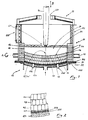
- the furnace consists of the vessel 21, which is mounted in a support structure 11 which can be tilted into the furnace platform (double arrow A), with the base 22 and the cover 23 which can be lifted off it an insulation 31 releasably flanged (212, 32, 223).
- the vessel 21, in particular the hearth 24 with the hearth sole 241, is delivered, that is to say provided with a refractory lining.
- the wall in the area of the hearth 24 is lined with magnesite stones 41 and the bottom with a plurality of layers 42, 43 and 44 made of graphite-containing magnesite stones, of which the bottom layer 42 with approx. 20% has the highest proportion of graphite, the following layer 43 one Share of approx. 10% and the third layer 44 has a graphite fraction below 10%, with the exception of a central region 43 ′, 44 ′, in which graphite-free magnesite stones are used at least in the upper stone layers.
- Remaining spaces between the wall lining 41 and the floor lining 42, 43, 44 are filled with refractory ramming compound 46.
- a graphite layer 47 is also inserted between the vessel bottom 22 and the bottom layer 42 of the bottom lining.
- Refractory, graphite-containing ramming compound can then also be applied to the uppermost stone layer 44; at least the uppermost layer 44 itself can also consist of refractory ramming compound.
- the vessel wall above the cooker 24 is formed by cooling elements, for example elements 213 through which cooling water flows or by spray cooling elements 213 '.
- An air baffle 224 is provided below the floor 22 for the floor cooling.
- the melt 61 In the hearth 24 there is the melt 61 with the slag 62 located on it.
- the focal spot 611 is formed in the center.
- the graphite electrode 71 which forms the cathode can be lowered and raised (double arrow B) in the central passage 231 in the vessel lid 23.
- the anode current is connected to the copper plating 222 of the vessel bottom 22 via the connections 226, 226 'extending through the sheet steel base 221'.
- the electrically conductive magnesite stones are recessed in the center of the bottom lining 42, 43, 44 in the upper layers 43, 44 and electrically non-conductive magnesite stones 43 ', 44' are used.
Landscapes
- Engineering & Computer Science (AREA)
- Chemical & Material Sciences (AREA)
- Textile Engineering (AREA)
- Mechanical Engineering (AREA)
- Organic Chemistry (AREA)
- General Engineering & Computer Science (AREA)
- Physics & Mathematics (AREA)
- Plasma & Fusion (AREA)
- Manufacturing & Machinery (AREA)
- Materials Engineering (AREA)
- Metallurgy (AREA)
- General Chemical & Material Sciences (AREA)
- Chemical Kinetics & Catalysis (AREA)
- Vertical, Hearth, Or Arc Furnaces (AREA)
- Furnace Housings, Linings, Walls, And Ceilings (AREA)
- Furnace Details (AREA)
- Discharge Heating (AREA)
- Arc Welding Control (AREA)
- Superconductors And Manufacturing Methods Therefor (AREA)
- Yarns And Mechanical Finishing Of Yarns Or Ropes (AREA)
Description
- Die Erfindung betrifft einen Gleichstrom-Lichtbogenofen der im Oberbegriff des Patentanspruchs 1 umrissenen Gattung.
- Bei Gleichstrom-Lichtbogenöfen ist es möglich, im Gegensatz zu Drehstrom-Lichtbogenöfen mit nur einer durch den Deckel des Ofens anstellbaren Graphitelektrode als Kathode und einer Bodenelektrode als Anode zu arbeiten. Anlagenseitig resultiert daraus ein geringerer konstruktiver Aufwand. Solche Gleichstrom-Lichtbogenöfen zeichnen sich dann auch durch einen wesentlich geringeren Elektrodenverbrauch sowie durch eine längere Standzeit der feuerfesten Auskleidung der Gefäßwandung aus. Was die Energieseite betrifft, ist der Verbrauch geringer, des weiteren kommt es zu merklich geringeren Netzrückwirkungen (Flicker-Erscheinungen). Der geringeren induktiven Einflüsse wegen kann bei der Ofenkonstruktion dann auch weitgehend auf die Verwendung austenitischer Stahlqualitäten verzichtet werden. Ein weiterer Vorteil des Gleichstrom-Lichtbogenofens sind seine geringere Geräuschemissionen.
- Gewisse Probleme wirft beim Gleichstrom-Lichtbogenofen die die Gegenelektrode zur kathodisch geschalteten, durch den Deckel des Gefäßes gegen den Herd anstellbaren Graphitelektrode bildende anodisch geschaltete Bodenelektrode auf. Hierfür hat man zunächst einen sich durch den Boden und die auf dem Boden aufsitzende feuerfeste Auskleidung durchdringenden Eisenkern vorgesehen, der allerdings zumal bei Schmelzen mit niedrigem Kohlenstoff- und hohem Sauerstoffgehalten einem schnellen Wegschmelzen unterworfen ist. Weitergehend hat man anstelle eines Eisenkerns mit vergleichsweise großem Querschnitt eine Mehrzahl von Stahlstäben vorgesehen, die sich von einer am Gefäßboden angesetzten, anodisch geschalteten Stahlplatte ausgehend bis zur Herdsohle erstrecken (DE-OS 34 09 255). Die Zustellung, das heißt das Ein- bzw. Aufbringen der feuerfesten Auskleidung bereitet hierbei erkennbar Schwierigkeiten. Schwierigkeiten bereitet auch das nachträgliche Eintreiben der Stahlstäbe in die feuerfeste Auskleidung bis zum Kontakt mit der anodisch geschalteten Bodenplatte. Soweit vorgeschlagen worden ist, den die Anode bildenden Bereich des Gefäßbodens auswechselbar auszubilden (DE-OS 35 35 692) ergeben sich entsprechende Probleme bei der Erstellung der Austauschelemente. In beiden Fällen bleibt die Ausbildung des Anodenbereichs im übrigen auf das Zentrum des Herdbodens beschränkt.
- Anstelle der die Anode ausbildendenden Stahlstäbe ist dann auch schon vorgeschlagen worden, die feuerfeste Bodenauskleidung selbst elektrisch leitend durch den Einsatz von blech- oder graphitummantelten Steinen oder aber Steinen mit einen höheren Graphitanteil auszubilden, wobei als Zwischenlage zwischen dem Gefäßboden aus Stahl und der feuerfesten Auskleidung auch schon eine Kupfereinlage ingestalt von Schienen oder Blechen vorgesehen wurde, an der der Anodenstrom liegt (DE-OS 35 34 750 und DE-OS 34 13 745). Eine Variante sieht eine mehrlagige feuerfeste Auskleidung des Gefäßbodens, bestehend aus mehreren Lagen von feuerfesten, elektrisch leitend ausgebildeten Steinen und einer darauf aufgebrachten feuerfesten Stampfmasse vor, wobei durch die Stampfmasse in Kontakt mit der obersten Steinlage gelangende Stahlstäbe getrieben sind (DE-OS 29 05 553). Auch hierbei ist bereits angesprochen, daß die feuerfeste Bodenauskleidung von einer anodisch geschalteten Kupferplatte unterfangen sein kann. Eine Kupferplatte selbst ist allerdings nicht geeignet, tragende Funktionen zu ubernehmen. Nach dem Stand der Technik ist deshalb ein Stahlblechboden vorgesehen, der mit einer Überdeckung aus stoßenden Kupferblechsegmenten versehen ist, die mit dem Stahlblechboden durch eine Vielzahl von Bolzen zusammengefaßt sind.
- Die Ausbildung des Gefäßbodens selbst als Anode erweist sich insoweit als vorteilhaft, als der Stromübergang bei größtmöglicher Kontaktfläche erfolgt, woraus eine niedrige spezifische Strombelastung des Gefäßbodens, speziell seiner feuerfesten Auskleidung, resultiert, was sich in einer Verbesserung der Standzeit des Bodens niederschlägt. Als nachteiligt erweist sich bei diesem Stand der Technik die Art und Weise der Zusammenfassung des tragenden Stahlblechbodens mit dem Kupferbelag, wofür bei übereinstimmendem Lochbild eine Vielzahl von Bohrungen in den Stahlblechboden und in die ihm zuzuordnenden Kupferblechsegmente einzubringen ist, durch die sich die die Elemente zusammenfassenden Bolzen erstrecken. Diese Art und Weise der Zusammenfassung von Stahlblechboden und Kupferblechsegmenten ist ersichtlich sehr aufwendig. Dabei verbleiben zwischen dem Stahlblechboden und der Kupferbelag dann zwangsläufig auch Luftspalte sowohl zwischen den Kupferblechsegmenten selbst als auch zwischen dem tragenden Stahlblechboden und den Kupfersegmenten, die im laufenden Betrieb unter der Einwirkung der hohen Betriebstemperatur dann auch noch eine Vergrösserung erfahren. Daraus resultiert das Risiko des Unterlaufens des Kupferbelages durch vom Einsatz herrührendes Schwermetall. Hierdurch wird die erforderliche Kühlung des Bodens beeinträchtigt, im Endeffekt dann auch die Bodenhaltbarkeit.
- Ausgehend vom Stand der Technik liegt der Erfindung die Aufgabe zugrunde, eine Lösung für den mit einem Kupferbelag versehenen Gefäßboden eines Gleichstrom-Lichtbogenofens anzugeben, die die insoweit aufgezeigten Nachteile vermeidet.
- Die Aufgabe wird bei gattungsgemäßen Gleichstrom-Lichtbogenöfen durch eine Ausbildung des Gefäßbodens entsprechend dem kennzeichnenden Teil des Patentanspruchs 1 gelöst.
- Bei dem erfindungsgemäß aus kupferplattiertem Stahlblech bestehenden Gefäßboden handelt es sich um ein einfaches, kompaktes Bauteil, das dementsprechend kostengünstig ist. Das Bauteil verbindet mit der gewünschten größtmöglichen Kontaktfläche für den Stromübergang die Vermeidung der Mängeln, mit denen nach dem Stand der Technik mit einem Kupferbelag in Gestalt von Schienen, Blechen bzw. Blechzuschnitten (Segmenten) versehene Stahlblechböden behaftet sind.
- Ausgestaltungen der Erfindung ergeben sich aus den Unteransprüchen. Die große Kontaktfläche für den Stromübergang gestattet es, ausgehend vom Boden einen abnehmenden Anteil von die elektrische Leitfähigkeit der feuerfesten Auskleidung hervorrufenden Bestandteilen, insbesondere Graphit, in der Auskleidung vorzusehen. Damit erhöht sich die Standzeit der feuerfesten Auskleidung. Mit entsprechender Zielsetzung kann vorgesehen sein, im Zentrum der Bodenauskleidung eine im wesentlichen von die elektrische Leitfähigkeit hervorrufenden Bestandteilen freie feuerfeste Auskleidung vorzusehen. Eine zwischen dem kupferplattiertem Stahlblechboden und der auf ihm aufsitzenden feuerfesten Auskleidung eingefügten Zwischenlage aus Graphit verbessert den Stromübergang vom Boden in die von ihm unterfangene Auskleidung. Anstelle einer Kupferplattierung für den tragenden Bestandteil des Gefäßbodens kann natürlich auch eine Plattierung aus einer Kupferlegierung mit hohem Kupferanteil vorgesehen sein.
- In der Zeichnung ist die Erfindung anhand eines in schematischer Weise dargestellten Gleichstrom-Lichtbogenofens weitergehend erläutert. Es zeigen:
- Figur 1
- den Lichtbogenofen im Schnitt,
- Figur 2
- einen Ausschnitt aus dem Gefäßboden in größerem Maßstab.
- Der Ofen besteht aus dem in einer in die Ofenplattform kippbar (Doppelpfeil A) integrierten Tragkonstruktion 11 gelagerten Gefäß 21 mit dem Boden 22 und dem von ihm abhebbaren Deckel 23. Der aus kupferplattiertem Stahlblech 221, 222 bestehende Boden 22 ist an den Gefäßmantel 211 unter Einfügung einer Isolierung 31 lösbar angeflanscht (212, 32, 223).
- Das Gefäß 21, insbesondere der Herd 24 mit der Herdsohle 241, ist zugestellt, also mit einer feuerfesten Auskleidung versehen. Konkret ist die Wandung im Bereich des Herdes 24 mit Magnesitsteinen 41 ausgekleidet und der Boden mit mehreren Lagen 42, 43 und 44 aus Graphit enthaltenden Magnesitsteinen, von denen die unterste Lage 42 mit ca. 20% den höchsten Graphitanteil aufweist, die folgende Lage 43 einen Anteil von ca. 10% und die dritte Lage 44 einen unter 10% liegenden Graphitanteil unter Aussparung eines zentrischen Bereichs 43′, 44′, in dem zumindest in den oberen Steinlagen graphitfreie Magnesitsteine eingesetzt sind. Verbleibende Zwischenräume zwischen der Wandausmauerung 41 und der Bodenausmauerung 42, 43, 44 sind mit feuerfester Stampfmasse 46 ausgefüllt. Zwischen dem Gefäßboden 22 und die unterste Lage 42 der Bodenauskleidung ist noch eine Graphitschicht 47 eingefügt. Auf die oberste Steinlage 44 kann dann auch noch feuerfeste, graphithaltige Stampfmasse aufgebracht sein, zumindest die oberste Lage 44 selbst kann auch aus feuerfester Stampfmasse bestehen. Die Gefäßwandung oberhalb des Herdes 24 wird gebildet von Kühlelementen, beispielsweise von kühlwasserdurchströmten Elementen 213 oder von Spritzkühlelementen 213′. Für die Bodenkühlung ist unterhalb des Bodens 22 ein Luftleitblech 224 vorgesehen.
- Im Herd 24 befindet sich die Schmelze 61 mit der auf ihr befindlichen Schlacke 62. Im Zentrum ist der Brennfleck 611 ausgebildet.
- Die die Kathode bildende Graphitelektrode 71 führt sich senk- und hebbar (Doppelpfeil B) in dem zentrischen Durchgang 231 im Gefäßdeckel 23. Der Anodenstrom liegt über die sich durch den Stahlblechboden 221 erstreckenden Anschlüsse 226, 226′ an der Kupferplattierung 222 des Gefäßbodens 22.
- Beim dargestellten Ofen sind im Zentrum der Bodenauskleidung 42, 43, 44 in den oberen Lagen 43, 44 die elektrisch leitend ausgebildeten Magnesitsteine ausgespart und elektrisch nichtleitende Magnesitsteine 43′, 44′ eingesetzt.
Claims (7)
- Gleichstrom-Lichtbogenofen mit einer durch den Deckel (23) des Gefäßes (21) gegen den Herd (24) anstellbaren kathodisch geschalteten Graphitelektrode (71), dessen die Anode bildender Gefäßboden aus einem tragenden Stahlblechboden (22) und einer darauf aufsitzenden Ausmauerung (42, 43, 44) aus feuerfestem, zumindest teilweise elektrisch leitendem Material besteht, wobei zwischen dem Stahlblechboden (22) und der feuerfesten Ausmauerung (42, 43, 44) eine Einlage aus Kupfer eingefügt ist, die anodisch geschaltet ist, gekennzeichnet durch einen kupferplattierten Stahlblechboden (221, 222) mit den Stahlblechboden (221) durchsetzenden, an der Kupferplattierung (222) liegenden Anschlüssen (226, 226′) für den Anodenstrom.
- Gleichstrom-Lichtbogenofen nach Anspruch 1, dadurch gekennzeichnet, daß die feuerfeste, auf dem Boden (22) aufsitzende Auskleidung (42, 43, 44) aus Graphit enthaltendem Material besteht.
- Gleichstrom-Lichtbogenofen nach Anspruch 1 oder Anspruch 2, dadurch gekennzeichnet, daß der Graphitgehalt der auf dem Gefäßboden aufsitzenden feuerfesten Auskleidung ausgehend vom Boden (22) zur Herdsohle (241) hin abnimmt.
- Gleichstrom-Lichtbogenofen nach Anspruch 3, dadurch gekennhzeichnet, daß der Graphitanteil im Bereich des Bodens ca. 20% beträgt und der Graphitanteil des des feuerfesten Materials im Bereich der Herdsohle (241) unter 10% liegt.
- Gleichstrom-Lichtbogenofen nach einem der Ansprüche 1 bis 4, dadurch gekennzeichnet, daß zwischen Boden (22) und der feuerfesten Auskleidung (42, 43, 44) eine Graphitschicht (47) eingefügt ist.
- Gleichstrom-Lichtbogenofen nach einem der Ansprüche 1 bis 5, gekennzeichnet durch eine im wesentlichen graphitfreie feuerfeste Auskleidung 43′, 44′) im zentrischen Bereich der Herdsohle (241).
- Gleichstrom-Lichtbogenofen nach einem der Ansprüche 1 bis 6, gekennzeichnet durch einen Kupferbelag (222) des Stahlblechbodens (221) einer Dicke von max. 10 mm.
Applications Claiming Priority (3)
| Application Number | Priority Date | Filing Date | Title |
|---|---|---|---|
| DE4022720 | 1990-07-17 | ||
| DE4022720A DE4022720A1 (de) | 1990-07-17 | 1990-07-17 | Untergefaess eines gleichstromlichtbogenofens |
| PCT/DE1991/000582 WO1992002112A1 (de) | 1990-07-17 | 1991-07-17 | Gleichstrom-lichtbogenofen |
Publications (2)
| Publication Number | Publication Date |
|---|---|
| EP0493557A1 EP0493557A1 (de) | 1992-07-08 |
| EP0493557B1 true EP0493557B1 (de) | 1995-01-11 |
Family
ID=6410452
Family Applications (1)
| Application Number | Title | Priority Date | Filing Date |
|---|---|---|---|
| EP91912847A Expired - Lifetime EP0493557B1 (de) | 1990-07-17 | 1991-07-17 | Gleichstrom-lichtbogenofen |
Country Status (10)
| Country | Link |
|---|---|
| US (1) | US5297159A (de) |
| EP (1) | EP0493557B1 (de) |
| JP (1) | JP3126380B2 (de) |
| KR (1) | KR940005839A (de) |
| AT (1) | ATE117158T1 (de) |
| CA (1) | CA2065423C (de) |
| DE (2) | DE4022720A1 (de) |
| DK (1) | DK0493557T3 (de) |
| ES (1) | ES2067239T3 (de) |
| WO (1) | WO1992002112A1 (de) |
Families Citing this family (7)
| Publication number | Priority date | Publication date | Assignee | Title |
|---|---|---|---|---|
| DE4339031C1 (de) * | 1993-11-15 | 1995-01-12 | Treibacher Chemische Werke Ag | Verfahren und Vorrichtung zur Herstellung eines Schleifmittels auf Basis Korund |
| DE4411591C2 (de) * | 1994-03-30 | 1996-06-05 | Mannesmann Ag | Bodenelektrode eines mit Gleichstrom beheizten Ofens |
| US5867523A (en) * | 1996-05-28 | 1999-02-02 | Hatch Associates Ltd. | Electric furnace with conductive hearth |
| DE19925599A1 (de) * | 1999-06-04 | 2000-12-07 | Sms Demag Ag | Verfahren und Vorrichtung zum Betrieb von Lichtbogenschmelzöfen und/oder Widerstandsschmelzöfen |
| EP2324825A1 (de) * | 2002-02-11 | 2011-05-25 | Bayer Healthcare LLC | Arylharnstoffe mit Angiogenese hemmender Aktivität |
| RU2394196C1 (ru) * | 2009-04-16 | 2010-07-10 | Сергей Иванович Огарышев | Плавильная печь |
| CN108773845A (zh) * | 2018-08-21 | 2018-11-09 | 刘凯 | 一种直流电电石炉 |
Family Cites Families (17)
| Publication number | Priority date | Publication date | Assignee | Title |
|---|---|---|---|---|
| US3952140A (en) * | 1972-08-02 | 1976-04-20 | Engineered Metal Products Company, Inc. | Modular divisible barrel-shaped shell for metallurgical furnaces |
| SE410654B (sv) * | 1978-02-28 | 1979-10-22 | Asea Ab | Likstromsljusbagsugn med minst en katodiskt ansluten elektrod och minst en bottnkontakt |
| SE415394B (sv) * | 1978-12-29 | 1980-09-29 | Asea Ab | Bottenkontakt vid likstromsljusbagsugn |
| SE423275B (sv) * | 1979-06-26 | 1982-04-26 | Asea Ab | Bottenkontakt vid likstromsljusbagsugn |
| SE431792B (sv) * | 1981-06-09 | 1984-02-27 | Asea Ab | Sett att driva en likstroms-ljusbagsugn |
| IT1177539B (it) * | 1984-02-02 | 1987-08-26 | Italimpianti | Perfezionamento nei forni elettronici ad arco di corrente continua |
| DE3413745C2 (de) * | 1983-04-21 | 1994-03-03 | Asea Ab | Gleichstromlichtbogenofen |
| SE452690B (sv) * | 1983-07-07 | 1987-12-07 | Asea Ab | Likstroms-ljusbagsugn |
| SE449132B (sv) * | 1984-01-25 | 1987-04-06 | Asea Ab | Likstromsljusbagsugn eller skenk for vermning |
| EP0150483B1 (de) * | 1984-01-31 | 1988-06-01 | BBC Brown Boveri AG | Bodenelektrodenarordnung für einen elektrischen Ofen |
| DE3409255A1 (de) * | 1984-03-14 | 1985-12-12 | Didier-Werke Ag, 6200 Wiesbaden | Herdboden, besonders fuer gleichstrom-lichtbogenoefen |
| DE3443574A1 (de) * | 1984-11-29 | 1986-05-28 | Fuchs Systemtechnik GmbH, 7601 Willstätt | Lichtbogenofen |
| DE3534750A1 (de) * | 1985-09-28 | 1987-04-16 | Krupp Gmbh | Boden eines elektrisch beheizten schmelzofens, insbesondere eines gleichstromofens |
| DE3535692A1 (de) * | 1985-10-05 | 1987-04-09 | Gutehoffnungshuette Man | Kontaktelektroden-anordnung fuer gleichstrom-lichtbogen- oder widerstands-schmelzoefen |
| US5173920A (en) * | 1989-08-21 | 1992-12-22 | Asea Brown Boveri Ltd. | Direct-current electric-arc furnace |
| US5052018A (en) * | 1989-10-12 | 1991-09-24 | Deutsche Voest-Alpine Industrieanlagen Gmbh | Anode for a direct current arc furnace |
| JP6128914B2 (ja) | 2013-03-27 | 2017-05-17 | 株式会社小松製作所 | 回転電機 |
-
1990
- 1990-07-17 DE DE4022720A patent/DE4022720A1/de not_active Withdrawn
-
1991
- 1991-07-17 ES ES91912847T patent/ES2067239T3/es not_active Expired - Lifetime
- 1991-07-17 DE DE59104251T patent/DE59104251D1/de not_active Expired - Fee Related
- 1991-07-17 JP JP03511974A patent/JP3126380B2/ja not_active Expired - Fee Related
- 1991-07-17 WO PCT/DE1991/000582 patent/WO1992002112A1/de not_active Ceased
- 1991-07-17 DK DK91912847.0T patent/DK0493557T3/da active
- 1991-07-17 CA CA002065423A patent/CA2065423C/en not_active Expired - Fee Related
- 1991-07-17 AT AT91912847T patent/ATE117158T1/de not_active IP Right Cessation
- 1991-07-17 US US07/838,743 patent/US5297159A/en not_active Expired - Fee Related
- 1991-07-17 EP EP91912847A patent/EP0493557B1/de not_active Expired - Lifetime
-
1993
- 1993-07-08 KR KR1019930012792A patent/KR940005839A/ko not_active Withdrawn
Also Published As
| Publication number | Publication date |
|---|---|
| JPH05502503A (ja) | 1993-04-28 |
| US5297159A (en) | 1994-03-22 |
| ES2067239T3 (es) | 1995-03-16 |
| CA2065423A1 (en) | 1992-01-18 |
| DK0493557T3 (da) | 1995-05-15 |
| EP0493557A1 (de) | 1992-07-08 |
| JP3126380B2 (ja) | 2001-01-22 |
| WO1992002112A1 (de) | 1992-02-06 |
| KR940005839A (ko) | 1994-03-22 |
| ATE117158T1 (de) | 1995-01-15 |
| DE4022720A1 (de) | 1992-01-23 |
| DE59104251D1 (de) | 1995-02-23 |
| CA2065423C (en) | 1996-04-23 |
Similar Documents
| Publication | Publication Date | Title |
|---|---|---|
| DE2312439C2 (de) | Kathodenwanne einer Aluminiumschmelzflußelektrolysezelle | |
| EP0731180B1 (de) | Kühlplatte für Schachtöfen | |
| DE2838965C2 (de) | Benetzbare Kathode für einen Schmelzflußelektrolyseofen | |
| DE3875437T2 (de) | Kathodenstromkollektor fuer die elektrogewinnung von aluminium. | |
| DE2905553A1 (de) | Gleichstrom-lichtbogenofen | |
| DE3413745C2 (de) | Gleichstromlichtbogenofen | |
| EP0705906B1 (de) | Kühlplatte für Schachtöfen | |
| EP0589150B1 (de) | Bodenelektrode für Gleichstrom-Lichtbogenöfen | |
| EP0151415B1 (de) | Gleichstrom-Lichtbogenofen oder Gleichstrom-Lichtbogenpfanne | |
| DE2943244A1 (de) | Gefaessdeckel fuer einen metallschmelzofen insbesondere elektrischen lichtbogenofen | |
| EP0493557A1 (de) | Gleichstrom-lichtbogenofen. | |
| EP0422406B1 (de) | Anode für einen Gleichstromlichtbogenofen | |
| DE3880940T2 (de) | ||
| EP0541044B1 (de) | Gleichstrom-Lichtbogenofen | |
| EP0887428A1 (de) | Kühlplatten für Schachtöfen | |
| DE3534750A1 (de) | Boden eines elektrisch beheizten schmelzofens, insbesondere eines gleichstromofens | |
| EP0530534B1 (de) | Ausmauerung für einen Gleichstrom-Lichtbogenofen | |
| DE3242209C2 (de) | ||
| DE19545984B4 (de) | Kühlplatte für Schmelzöfen | |
| EP0753077B1 (de) | Gleichstrombeheiztes metallurgisches gefäss mit bodenelektrode | |
| EP0699885B1 (de) | Ofengefäss für einen Gleichstromlichtbogenofen | |
| DE4126237C2 (de) | ||
| EP0291680B1 (de) | Lichtbogenofen mit einem auf einer Seite des Ofengefässes vorgesehenen Aufnahmeraum für Chargiergut | |
| DE2718293C2 (de) | ||
| DE3120170A1 (de) | "vorrichtung zur schmelzreduktion und zur gaserzeugung" |
Legal Events
| Date | Code | Title | Description |
|---|---|---|---|
| PUAI | Public reference made under article 153(3) epc to a published international application that has entered the european phase |
Free format text: ORIGINAL CODE: 0009012 |
|
| 17P | Request for examination filed |
Effective date: 19920224 |
|
| AK | Designated contracting states |
Kind code of ref document: A1 Designated state(s): AT BE CH DE DK ES FR GB GR IT LI LU NL SE |
|
| 17Q | First examination report despatched |
Effective date: 19931112 |
|
| GRAA | (expected) grant |
Free format text: ORIGINAL CODE: 0009210 |
|
| AK | Designated contracting states |
Kind code of ref document: B1 Designated state(s): AT BE CH DE DK ES FR GB GR IT LI LU NL SE |
|
| PG25 | Lapsed in a contracting state [announced via postgrant information from national office to epo] |
Ref country code: GR Free format text: LAPSE BECAUSE OF FAILURE TO SUBMIT A TRANSLATION OF THE DESCRIPTION OR TO PAY THE FEE WITHIN THE PRESCRIBED TIME-LIMIT Effective date: 19950111 |
|
| REF | Corresponds to: |
Ref document number: 117158 Country of ref document: AT Date of ref document: 19950115 Kind code of ref document: T |
|
| ITF | It: translation for a ep patent filed | ||
| REF | Corresponds to: |
Ref document number: 59104251 Country of ref document: DE Date of ref document: 19950223 |
|
| REG | Reference to a national code |
Ref country code: ES Ref legal event code: FG2A Ref document number: 2067239 Country of ref document: ES Kind code of ref document: T3 |
|
| ET | Fr: translation filed | ||
| REG | Reference to a national code |
Ref country code: DK Ref legal event code: T3 |
|
| GBT | Gb: translation of ep patent filed (gb section 77(6)(a)/1977) |
Effective date: 19950420 |
|
| PLBE | No opposition filed within time limit |
Free format text: ORIGINAL CODE: 0009261 |
|
| STAA | Information on the status of an ep patent application or granted ep patent |
Free format text: STATUS: NO OPPOSITION FILED WITHIN TIME LIMIT |
|
| 26N | No opposition filed | ||
| PGFP | Annual fee paid to national office [announced via postgrant information from national office to epo] |
Ref country code: GB Payment date: 20000719 Year of fee payment: 10 |
|
| PGFP | Annual fee paid to national office [announced via postgrant information from national office to epo] |
Ref country code: SE Payment date: 20000725 Year of fee payment: 10 |
|
| PGFP | Annual fee paid to national office [announced via postgrant information from national office to epo] |
Ref country code: LU Payment date: 20000727 Year of fee payment: 10 Ref country code: DK Payment date: 20000727 Year of fee payment: 10 |
|
| PGFP | Annual fee paid to national office [announced via postgrant information from national office to epo] |
Ref country code: NL Payment date: 20000731 Year of fee payment: 10 |
|
| PGFP | Annual fee paid to national office [announced via postgrant information from national office to epo] |
Ref country code: BE Payment date: 20000918 Year of fee payment: 10 |
|
| PGFP | Annual fee paid to national office [announced via postgrant information from national office to epo] |
Ref country code: CH Payment date: 20000927 Year of fee payment: 10 |
|
| PG25 | Lapsed in a contracting state [announced via postgrant information from national office to epo] |
Ref country code: LU Free format text: LAPSE BECAUSE OF NON-PAYMENT OF DUE FEES Effective date: 20010717 Ref country code: GB Free format text: LAPSE BECAUSE OF NON-PAYMENT OF DUE FEES Effective date: 20010717 Ref country code: DK Free format text: LAPSE BECAUSE OF NON-PAYMENT OF DUE FEES Effective date: 20010717 |
|
| PG25 | Lapsed in a contracting state [announced via postgrant information from national office to epo] |
Ref country code: SE Free format text: LAPSE BECAUSE OF NON-PAYMENT OF DUE FEES Effective date: 20010718 |
|
| PG25 | Lapsed in a contracting state [announced via postgrant information from national office to epo] |
Ref country code: LI Free format text: LAPSE BECAUSE OF NON-PAYMENT OF DUE FEES Effective date: 20010731 Ref country code: CH Free format text: LAPSE BECAUSE OF NON-PAYMENT OF DUE FEES Effective date: 20010731 Ref country code: BE Free format text: LAPSE BECAUSE OF NON-PAYMENT OF DUE FEES Effective date: 20010731 |
|
| BERE | Be: lapsed |
Owner name: FLOHE G.M.B.H. & CO. Effective date: 20010731 |
|
| PG25 | Lapsed in a contracting state [announced via postgrant information from national office to epo] |
Ref country code: NL Free format text: LAPSE BECAUSE OF NON-PAYMENT OF DUE FEES Effective date: 20020201 |
|
| EUG | Se: european patent has lapsed |
Ref document number: 91912847.0 |
|
| GBPC | Gb: european patent ceased through non-payment of renewal fee |
Effective date: 20010717 |
|
| REG | Reference to a national code |
Ref country code: CH Ref legal event code: PL |
|
| REG | Reference to a national code |
Ref country code: DK Ref legal event code: EBP |
|
| NLV4 | Nl: lapsed or anulled due to non-payment of the annual fee |
Effective date: 20020201 |
|
| PGFP | Annual fee paid to national office [announced via postgrant information from national office to epo] |
Ref country code: ES Payment date: 20030725 Year of fee payment: 13 Ref country code: AT Payment date: 20030725 Year of fee payment: 13 |
|
| PGFP | Annual fee paid to national office [announced via postgrant information from national office to epo] |
Ref country code: FR Payment date: 20030730 Year of fee payment: 13 |
|
| PG25 | Lapsed in a contracting state [announced via postgrant information from national office to epo] |
Ref country code: AT Free format text: LAPSE BECAUSE OF NON-PAYMENT OF DUE FEES Effective date: 20040717 |
|
| PG25 | Lapsed in a contracting state [announced via postgrant information from national office to epo] |
Ref country code: ES Free format text: LAPSE BECAUSE OF NON-PAYMENT OF DUE FEES Effective date: 20040719 |
|
| PGFP | Annual fee paid to national office [announced via postgrant information from national office to epo] |
Ref country code: DE Payment date: 20050124 Year of fee payment: 14 |
|
| PG25 | Lapsed in a contracting state [announced via postgrant information from national office to epo] |
Ref country code: FR Free format text: LAPSE BECAUSE OF NON-PAYMENT OF DUE FEES Effective date: 20050331 |
|
| REG | Reference to a national code |
Ref country code: FR Ref legal event code: ST |
|
| PG25 | Lapsed in a contracting state [announced via postgrant information from national office to epo] |
Ref country code: IT Free format text: LAPSE BECAUSE OF NON-PAYMENT OF DUE FEES;WARNING: LAPSES OF ITALIAN PATENTS WITH EFFECTIVE DATE BEFORE 2007 MAY HAVE OCCURRED AT ANY TIME BEFORE 2007. THE CORRECT EFFECTIVE DATE MAY BE DIFFERENT FROM THE ONE RECORDED. Effective date: 20050717 |
|
| REG | Reference to a national code |
Ref country code: ES Ref legal event code: FD2A Effective date: 20040719 |
|
| PG25 | Lapsed in a contracting state [announced via postgrant information from national office to epo] |
Ref country code: DE Free format text: LAPSE BECAUSE OF NON-PAYMENT OF DUE FEES Effective date: 20060201 |