EP0492575B1 - Interstage casing for a pump made of sheet metal and method of manufacturing the same - Google Patents
Interstage casing for a pump made of sheet metal and method of manufacturing the same Download PDFInfo
- Publication number
- EP0492575B1 EP0492575B1 EP91122108A EP91122108A EP0492575B1 EP 0492575 B1 EP0492575 B1 EP 0492575B1 EP 91122108 A EP91122108 A EP 91122108A EP 91122108 A EP91122108 A EP 91122108A EP 0492575 B1 EP0492575 B1 EP 0492575B1
- Authority
- EP
- European Patent Office
- Prior art keywords
- cylindrical
- cylindrical portion
- open end
- outside diameter
- interstage
- Prior art date
- Legal status (The legal status is an assumption and is not a legal conclusion. Google has not performed a legal analysis and makes no representation as to the accuracy of the status listed.)
- Expired - Lifetime
Links
Images


Classifications
-
- F—MECHANICAL ENGINEERING; LIGHTING; HEATING; WEAPONS; BLASTING
- F04—POSITIVE - DISPLACEMENT MACHINES FOR LIQUIDS; PUMPS FOR LIQUIDS OR ELASTIC FLUIDS
- F04D—NON-POSITIVE-DISPLACEMENT PUMPS
- F04D29/00—Details, component parts, or accessories
-
- F—MECHANICAL ENGINEERING; LIGHTING; HEATING; WEAPONS; BLASTING
- F04—POSITIVE - DISPLACEMENT MACHINES FOR LIQUIDS; PUMPS FOR LIQUIDS OR ELASTIC FLUIDS
- F04D—NON-POSITIVE-DISPLACEMENT PUMPS
- F04D29/00—Details, component parts, or accessories
- F04D29/40—Casings; Connections of working fluid
- F04D29/42—Casings; Connections of working fluid for radial or helico-centrifugal pumps
- F04D29/426—Casings; Connections of working fluid for radial or helico-centrifugal pumps especially adapted for liquid pumps
- F04D29/4266—Casings; Connections of working fluid for radial or helico-centrifugal pumps especially adapted for liquid pumps made of sheet metal
-
- F—MECHANICAL ENGINEERING; LIGHTING; HEATING; WEAPONS; BLASTING
- F04—POSITIVE - DISPLACEMENT MACHINES FOR LIQUIDS; PUMPS FOR LIQUIDS OR ELASTIC FLUIDS
- F04D—NON-POSITIVE-DISPLACEMENT PUMPS
- F04D1/00—Radial-flow pumps, e.g. centrifugal pumps; Helico-centrifugal pumps
- F04D1/06—Multi-stage pumps
- F04D1/063—Multi-stage pumps of the vertically split casing type
Definitions
- the present invention relates to an interstage casing for a pump made of sheet metal and a method of manufacturing the same, and more particularly to an interstage casing for a pump made of sheet metal and pressed to shape for use in a multistage centrifugal pump and to a method of manufacturing the above interstage casing.
- interstage casing for a pump made of sheet metal in which a casing is formed of sheet metal such as a stainless steel and manufactured by press work.
- FIG. 6 of the accompanying drawings the interstage casing is of a cylindrical receptacle-like structure comprising a cylindrical side wall 1 and a bottom wall 2 on an end thereof (on lefthand side) which is connected to a preceding interstage casing.
- the opposite axial end surfaces, denoted at 3a, 4a, respectively, of the cylindrical receptacle-like structure are formed by machining a bottom end 3 and an open end 4 perpendicularly to the axis of the interstage casing.
- the bottom end 3 has a radially outer surface 3b
- the open end 4 has a radially inner surface 4b.
- the radially outer and inner surfaces 3b, 4b of adjacent interstage casings are machined so that they fit one over the other, providing a spigot joint.
- the desired dimensional accuracy of the axial ends 3a, 4a and the spigot joint surfaces 3b, 4b is maintained by the machining process described above.
- the interstage casing houses a guide vane 6 surrounding an impeller 5.
- the interstage casing has a return passage 8 defined laterally of the guide vane 6 and between the guide vane 6 and a guide vane side wall 7 that is welded to the cylindrical receptacle-like structure of a next adjacent interstage casing.
- the interstage casing also accommodates a shaft 9 on which the impeller 5 is mounted.
- a liner ring 10 is attached to the bottom wall 2 and positioned between the inner circumferential surface thereof and the impeller 5.
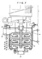
- FIG. 7 of the accompanying drawings shows in fragmentary cross section a vertical-shaft multistage centrifugal pump comprising interstage casings each of the structure shown in FIG. 6.
- the interstage casings, each denoted at 1a in FIG. 7, are assembled within an outer casing 11 having a suction port 12 and a discharge port 13.
- the shaft 9 is rotatably supported in the outer casing 11 through a shaft seal device 14.
- the liquid to be pumped is drawn from the suction port 12 and pressurized by the successive impellers 5 in the interstage casings 1a.
- the pressure head of the liquid is restored as the liquid passes through each of the guide vanes 6 and the return passages 8. Finally, the liquid is discharged out of the pump through the discharge port 13.
- the interstage casing of pressed sheet metal shown in FIG. 6 maintains a desired degree of dimensional accuracy for diameters and heights through the machining of the four regions, i.e., the radially outer surface 3b and the axial end surface 3a of the male member of a spigot joint on the bottom end 3, and the radially inner surface 4b and the axial end surface 4a of the female member of a spigot joint on the open end 4.
- the dimensional accuracy of these machined structures is considerably lower than that of casted structures because the wall thickness of the interstage casing structure is small.
- the cylindrical shape thereof tends to be deformed into an elliptical shape with a dimensional error ranging from 0.3 to 0.5 mm. Since the machined regions are reduced in thickness, it is necessary that the interstage casing blank be thick enough to provide desired mechanical strength.
- the invention relates to a pump made of sheet metal as referred to in the independent claims. Preferred embodiments are disclosed in the dependent claims.
- Another object of the present invention is to provide a method of manufacturing an interstage casing for a pump which can reduce the total number of steps to manufacture the interstage casing.
- an interstage casing for a pump made of sheet metal comprising: a cylindrical side wall having an open end on an end thereof, the open end having an axial end surface and a radially inner surface serving as a female member of a spigot joint; a bottom wall substantially perpendicular to the cylindrical side wall; a cylindrical portion provided between the bottom wall and the cylindrical side wall and having an outside diameter slightly smaller than an inside diameter of the open end of the cylindrical side wall; and a flat portion provided between the cylindrical portion and the cylindrical side wall so as to be engageable with the end surface of the open end of an adjacent interstage casing, the flat portion having an outside diameter slightly larger than an outside diameter of the open end.
- a method of manufacturing an interstage casing for a pump made of sheet metal comprising the steps of: forming a first pressed blank in the form of a cylindrical receptacle having a bottom wall, a first cylindrical portion joined to the bottom wall, and a second cylindrical portion having an outside diameter slightly larger than the outside diameter of the first cylindrical portion; and axially pressing the first pressed blank finally into an interstage casing while confining an end surface of an open end of the second cylindrical portion and radially inner and outer surfaces of the second cylindrical portion which extend from the end surface to a region near the first cylindrical portion and also confining a radially inner surface of the first cylindrical portion.
- the cylindrical portion is integrally joined to the bottom wall and disposed between the bottom wall and the cylindrical side wall, the cylindrical portion having a radially outer surface serving as the male member of a spigot joint.
- the cylindrical side wall has the radially inner surface serving as the female member of a spigot joint.
- the flat portion is integrally joined to the cylindrical portion through the recessed portion. When the radially inner surface is fitted over the radially outer surface of the cylindrical portion, the end surface of the open end of the adjacent interstage casing is held against the flat portion.
- the radially inner surface of the open end, the radially outer surface of the cylindrical portion, the flat portion, and the end surface of the open end are accurately pressed by a die assembly depending on the accuracy of the die assembly.
- the interstage casing is not subject to errors which would otherwise occur due to a machining process.
- the interstage casing further comprises a recessed portion provided between the cylindrical portion and the cylindrical side wall, the recessed portion being smaller in diameter than the cylindrical portion.
- An O ring can be mounted on the recessed potion, therefore, the interstage casing can employ an O ring which is most generally used as an interstage seal in multistage pumps. Consequently, the interstage casing of pressed sheet metal is widely applicable to high-pressure pumps.
- FIGS. 1 through 4 An interstage casing for a pump made of sheet metal according to an embodiment of the present invention will be described with reference to FIGS. 1 through 4.
- FIG. 1 shows in fragmentary cross section an upper half of an interstage casing according to an embodiment of the present invention.
- the interstage casing is used particularly in a multistage centrifugal pump.
- an interstage casing is in the form of a deformed cylindrical receptacle-like body comprising a cylindrical side wall 21 having a wall thickness t.
- the cylindrical side wall 21 has on an open end thereof an axial end surface 22 and a radially inner surface 23 as the female member of a spigot joint.
- the cylindrical receptacle-like body also includes a bottom wall 24 opposite to the open end. Between the cylindrical side wall 21 and the bottom wall 24, there are provided a cylindrical portion 25 joined to the bottom wall 24 and having an outside diameter that is substantially equal to or slightly smaller than the inside diameter of the open end, and a recessed portion 26 integrally joined to the cylindrical portion 25 and having a diameter smaller than that of the cylindrical portion 25.
- the cylindrical portion 25 serves as the male member of a spigot joint.
- the recessed portion 26 is joined to a flat portion 27 serving as a bottom wall end surface and integrally joined to the cylindrical side wall 21 through a protruding portion 28 that projects radially outwardly from the outer surface of the cylindrical side wall 21.
- the protruding portion 28 has an inside diameter smaller than the outside diameter of the open end of the cylindrical side wall 21.
- the protruding portion 28 has an outside diameter larger than the outside diameter of the open end of the cylindrical side wall 21, thus providing support for the axial end surface 22 of the cylindrical side wall of an adjacent interstage casing.
- the difference 2h between the outside diameter of the protruding portion 28 and the outside diameter of the cylindrical side wall 21 at the open end thereof is selected to be equal to or less than twice the wall thickness t.
- the protruding portion 28 has an inside diameter smaller than the outside diameter of the open end of the cylindrical side wall 21.
- the bottom wall 24 has a radially inner flange 29 for supporting a liner ring (not shown), the radially inner flange 29 defining a fluid passage 30 radially inwardly thereof.
- FIG. 2 fragmentarily shows the interstage casing shown in FIG. 1 which is fitted in an adjacent interstage casing.
- the axial end surface 22 of the open end of the adjacent interstage casing is held in abutment against the flat portion 27 as the bottom wall end surface of the interstage casing.
- the radially inner surface 23 of the open end of the adjacent interstage casing is fitted over the cylindrical portion 25 joined to the bottom wall 24 of the interstage casing, with an O ring 31 mounted on the recessed portion 26.
- the flat portion 27 extends perpendicularly to the cylindrical side wall 21.
- the axial end surface 22 has a full or substantially full surface area that engages the flat portion 27.
- the flat portion 27 may be inclined with respect to the cylindrical side wall 21 at certain angle so long as the contacting area of the flat portion 27 and the axial end surface 22 is secured.
- the radially inner surface 23 and the cylindrical portion 25, which are fitted together as a spigot joint, and the axial end surface 22 and the flat portion 27 that abut against each other are fabricated by molds with their dimensional accuracy achieved by the dimensional accuracy of the molds themselves.
- the interstage casing may be formed by bulging, which is one of the press forming processes.
- the inside diameter A of the protruding portion 28 is smaller than the outside diameter B of the open end of the cylindrical side wall 21, when the adjacent interstage casings are fastened to join them to each other, axial forces and internal pressure are developed to produce an axial force F which is applied as a compressive stress, but not as a bending stress, to the protruding portion 28. If the outside diameter B were smaller than the inside diameter A, then the protruding portion 28 would be subject to a bending stress, making it necessary to give certain mechanical strength to the local region to which the bending stress would be applied.
- the inside diameter A of the protruding portion 28 affects the flat portion 27 as the bottom wall end surface, it is necessary that the flat portion 27 provide a sufficient flat area.
- the radially outward projection of the protruding portion 28 may not necessarily be required if the flat portion 27 provides a sufficient flat area.
- FIG. 3 shows the upper half of the interstage casing shown in FIG. 1 with a return blade attached thereto.
- a return blade 32 is welded to the outer surface of the bottom wall 24 of the interstage casing.
- a side plate 33 is attached to a lateral end of the return blade 32 so that the return blade 32 is sandwiched between the side plate 33 and the bottom wall 24.
- An impeller 34 is mounted on a shaft 35 and housed in the interstage casing.
- a liner ring 36 is attached to the radially inner surface of the flange 29 in surrounding relation to an inlet of the impeller 34.
- the liquid discharged out of the impeller in the preceding interstage casing flows through a passage defined by the return blade 32 sandwiched between the bottom wall 24 and the side plate 33, and is introduced into the inlet of the impeller 34 of the next stage.
- the liquid is directed to a next impeller through a passage that is defined by a return blade 32 of a next interstage casing (on the righthand side as shown).
- the liner ring 36 around the inlet of the impeller 34 is attached to the flange 29 of the bottom wall 24 for preventing the liquid from leaking out under pressure.
- FIG. 4 shows the upper half of the interstage casing shown in FIG. 1 with a guide vane 41 housed therein.
- a guide vane 41 is disposed around the impeller 34.
- a side plate 42 is attached to a side (facing the preceding interstage casing) of the guide vane 41, defining a passage 41a for restoring the pressure of the liquid to be pumped.
- a return passage 41b is defined between the guide vane 41 and the bottom wall 24a of the next interstage casing, the return passage 41b communicating with the passage 41a.
- the guide vane 41 collects the liquid discharged from the impeller 34, and the liquid is sent to the next interstage casing through the passage 41a which restores the pressure of the liquid and the return passage 41b communicating therewith.
- a sheet metal such as a steel plate is blanked into a circular blank, which is pressed into a first pressed blank in the form of a cylindrical receptacle having a first cylindrical portion joined to a bottom wall and a second cylindrical portion joined to the first cylindrical portion and having an outside diameter slightly larger than the outside diameter of the first cylindrical portion.
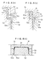
- the first pressed blank is pressed to a final shape using a die assembly M as shown in FIGS. 5(a) through 5(c).
- the die assembly M comprises an upper die 51, a radially inner lower die 52, and a radially outer lower die 53.
- FIG. 5(a) shows the first pressed blank, denoted at 50, placed in the die assembly M before being finally shaped.
- the first cylindrical portion, denoted at 50a is fitted over a smaller-diameter portion 52a of the radially inner lower die 52
- the second cylindrical portion, denoted at 50b is fitted over a larger-diameter portion 52b of the radially inner lower die 52.
- an intermediate step 50c by which the first and second cylindrical portions 50a, 50b are joined engages with a first step 52c of the radially inner lower die 52.
- the second cylindrical portion 50b has a lower end 50d held in abutment against a second step 52d of the radially inner lower die 52.
- the upper die 51 is moved downwardly from the position shown in FIG. 5(a) toward the lower dies 52, 53.
- the first pressed blank 50 is axially or vertically pressed into a shape shown in FIG. 5(b).
- the first cylindrical portion 50a is formed with the cylindrical potion 25 and the recessed portion 26 smaller in diameter than the cylindrical portion 25, and the intermediate step 50c is formed with the flat portion 27 joined to the recessed portion 26.
- the outside diameter of the cylindrical portion 25 is forcibly set to a predetermined dimension by an inner circumferential surface 51a of the upper die 51
- the inside diameter of the recessed portion 26 is forcibly set to a predetermined dimension by the smaller-diameter portion 52a of the radially inner lower die 52
- the flat portion 27 is also forcibly set to a predetermined degree of flatness by an end surface 51b of the upper die 51 and the first step 52c of the radially inner lower die 52.
- the second cylindrical portion 50b is formed with the protruding portion 28 contiguous to the flat portion 27 and projecting radially outwardly.
- the outside diameter of the protruding portion 28 is forcibly set to a predetermined dimension by a tapered inner circumferential surface 53a of the radially outer lower die 53.
- the interstage casing according to the present invention offers the following advantages: Since the interstage casing is not machined, it is not deformed or subjected to dimensional errors by forces that would be applied if the steel sheet were fastened for machining, and by stresses and heat that would be developed if the steel sheet were machined. The desired dimensional accuracy of certain regions of the interstage can be achieved by the dimensional accuracy of the die assembly used.
- the total number of steps required to fabricate the interstage casing is reduced because the machining process, which is entirely different from the press forming process, is eliminated.
- the interstage casing may be uniform in thickness, have a relatively small weight, and be reduced in cost.
- An O ring may be mounted on the recessed portion that is smaller in diameter than the cylindrical portion joined to the bottom wall and serving as the male member of a spigot joint. Therefore, the interstage casing, which is formed of pressed sheet metal, can be used in environments that should be free from liquid leakage and in pumps that develop relatively high pressures.
Abstract
Description
- The present invention relates to an interstage casing for a pump made of sheet metal and a method of manufacturing the same, and more particularly to an interstage casing for a pump made of sheet metal and pressed to shape for use in a multistage centrifugal pump and to a method of manufacturing the above interstage casing.
- Conventionally, there is known an interstage casing for a pump made of sheet metal in which a casing is formed of sheet metal such as a stainless steel and manufactured by press work. This type of interstage casing is shown in FIG. 6 of the accompanying drawings. As shown in FIG. 6, the interstage casing is of a cylindrical receptacle-like structure comprising a
cylindrical side wall 1 and abottom wall 2 on an end thereof (on lefthand side) which is connected to a preceding interstage casing. The opposite axial end surfaces, denoted at 3a, 4a, respectively, of the cylindrical receptacle-like structure are formed by machining a bottom end 3 and anopen end 4 perpendicularly to the axis of the interstage casing. The bottom end 3 has a radiallyouter surface 3b, and theopen end 4 has a radially inner surface 4b. The radially outer andinner surfaces 3b, 4b of adjacent interstage casings are machined so that they fit one over the other, providing a spigot joint. The desired dimensional accuracy of the axial ends 3a, 4a and thespigot joint surfaces 3b, 4b is maintained by the machining process described above. - The interstage casing houses a
guide vane 6 surrounding animpeller 5. The interstage casing has areturn passage 8 defined laterally of theguide vane 6 and between theguide vane 6 and a guidevane side wall 7 that is welded to the cylindrical receptacle-like structure of a next adjacent interstage casing. The interstage casing also accommodates ashaft 9 on which theimpeller 5 is mounted. Aliner ring 10 is attached to thebottom wall 2 and positioned between the inner circumferential surface thereof and theimpeller 5. - FIG. 7 of the accompanying drawings shows in fragmentary cross section a vertical-shaft multistage centrifugal pump comprising interstage casings each of the structure shown in FIG. 6. The interstage casings, each denoted at 1a in FIG. 7, are assembled within an
outer casing 11 having asuction port 12 and a discharge port 13. Theshaft 9 is rotatably supported in theouter casing 11 through ashaft seal device 14. - When the multistage centrifugal pump is in operation, the liquid to be pumped is drawn from the
suction port 12 and pressurized by thesuccessive impellers 5 in theinterstage casings 1a. The pressure head of the liquid is restored as the liquid passes through each of theguide vanes 6 and thereturn passages 8. Finally, the liquid is discharged out of the pump through the discharge port 13. - The interstage casing of pressed sheet metal shown in FIG. 6 maintains a desired degree of dimensional accuracy for diameters and heights through the machining of the four regions, i.e., the radially
outer surface 3b and the axial end surface 3a of the male member of a spigot joint on the bottom end 3, and the radially inner surface 4b and the axial end surface 4a of the female member of a spigot joint on theopen end 4. The dimensional accuracy of these machined structures is considerably lower than that of casted structures because the wall thickness of the interstage casing structure is small. When the machined casing structure is removed from a machine tool, the cylindrical shape thereof tends to be deformed into an elliptical shape with a dimensional error ranging from 0.3 to 0.5 mm. Since the machined regions are reduced in thickness, it is necessary that the interstage casing blank be thick enough to provide desired mechanical strength. - Sealing between the interstage casings is achieved by liquid gaskets that are of relatively low reliability since no installation space is available between the interstage casings for O-rings that are widely used in pump casings made by casting. Consequently, the interstage casings with liquid gaskets are not suitable for use in applications that require the development of very high pressures or environments that should be kept from the leakage of the liquid from the pump. With respect to the prior art, attention is drawn to German Laid-Open Publication DE-3816280, in which a casing for a centrifugal pump is disclosed. The casing consists of two parts with differ in outer diameter. At least the outer part is cup-shaped.
- The invention relates to a pump made of sheet metal as referred to in the independent claims. Preferred embodiments are disclosed in the dependent claims.
- It is therefore an object of the present invention to provide an interstage casing for a pump, made of sheet metal pressed to shape, which is free from machining processes that would otherwise be necessary to produce highly accurate regions, and hence from mechanical failures and dimensional errors that would otherwise possibly result from such machining processes, and which allows general O rings to be used as seals between the stages of the pump.
- Another object of the present invention is to provide a method of manufacturing an interstage casing for a pump which can reduce the total number of steps to manufacture the interstage casing.
- To achieve the above object, there is provided in accordance with one aspect of the present invention an interstage casing for a pump made of sheet metal, comprising: a cylindrical side wall having an open end on an end thereof, the open end having an axial end surface and a radially inner surface serving as a female member of a spigot joint; a bottom wall substantially perpendicular to the cylindrical side wall; a cylindrical portion provided between the bottom wall and the cylindrical side wall and having an outside diameter slightly smaller than an inside diameter of the open end of the cylindrical side wall; and a flat portion provided between the cylindrical portion and the cylindrical side wall so as to be engageable with the end surface of the open end of an adjacent interstage casing, the flat portion having an outside diameter slightly larger than an outside diameter of the open end.
- According to another aspect of the present invention, there is provided a method of manufacturing an interstage casing for a pump made of sheet metal, comprising the steps of: forming a first pressed blank in the form of a cylindrical receptacle having a bottom wall, a first cylindrical portion joined to the bottom wall, and a second cylindrical portion having an outside diameter slightly larger than the outside diameter of the first cylindrical portion; and axially pressing the first pressed blank finally into an interstage casing while confining an end surface of an open end of the second cylindrical portion and radially inner and outer surfaces of the second cylindrical portion which extend from the end surface to a region near the first cylindrical portion and also confining a radially inner surface of the first cylindrical portion.
- The cylindrical portion is integrally joined to the bottom wall and disposed between the bottom wall and the cylindrical side wall, the cylindrical portion having a radially outer surface serving as the male member of a spigot joint. The cylindrical side wall has the radially inner surface serving as the female member of a spigot joint. The flat portion is integrally joined to the cylindrical portion through the recessed portion. When the radially inner surface is fitted over the radially outer surface of the cylindrical portion, the end surface of the open end of the adjacent interstage casing is held against the flat portion. The radially inner surface of the open end, the radially outer surface of the cylindrical portion, the flat portion, and the end surface of the open end are accurately pressed by a die assembly depending on the accuracy of the die assembly. The interstage casing is not subject to errors which would otherwise occur due to a machining process.
- The interstage casing further comprises a recessed portion provided between the cylindrical portion and the cylindrical side wall, the recessed portion being smaller in diameter than the cylindrical portion. An O ring can be mounted on the recessed potion, therefore, the interstage casing can employ an O ring which is most generally used as an interstage seal in multistage pumps. Consequently, the interstage casing of pressed sheet metal is widely applicable to high-pressure pumps.
- The above and other objects, features, and advantages of the present invention will become apparent from the following description when taken in conjunction with the accompanying drawings which illustrate a preferred embodiment of the present invention by way of example.
-
- FIG. 1 is a fragmentary cross-sectional view of an upper half of an interstage casing according to an embodiment of the present invention;
- FIG. 2 is an enlarged fragmentary cross-sectional view showing the manner in which adjacent interstage casings according to the present invention fit one over the other;
- FIG. 3 is a fragmentary cross-sectional view of the upper half of the interstage casing with a return blade attached thereto according to the present invention;
- FIG. 4 is a fragmentary cross-sectional view of the upper half of the interstage casing with a guide vane housed therein according to the present invention;
- FIGS. 5(a), 5(b), and 5(c) are enlarged cross-sectional view showing a process of manufacturing the interstage casing according to the present invention;
- FIG. 6 is a fragmentary cross-sectional view of a conventional interstage casing; and
- FIG. 7 is a longitudinal cross-sectional view of a multistage centrifugal pump with the conventional interstage casings.
- An interstage casing for a pump made of sheet metal according to an embodiment of the present invention will be described with reference to FIGS. 1 through 4.
- FIG. 1 shows in fragmentary cross section an upper half of an interstage casing according to an embodiment of the present invention. The interstage casing is used particularly in a multistage centrifugal pump.
- As shown in FIG. 1, an interstage casing is in the form of a deformed cylindrical receptacle-like body comprising a
cylindrical side wall 21 having a wall thickness t. Thecylindrical side wall 21 has on an open end thereof anaxial end surface 22 and a radiallyinner surface 23 as the female member of a spigot joint. The cylindrical receptacle-like body also includes abottom wall 24 opposite to the open end. Between thecylindrical side wall 21 and thebottom wall 24, there are provided acylindrical portion 25 joined to thebottom wall 24 and having an outside diameter that is substantially equal to or slightly smaller than the inside diameter of the open end, and arecessed portion 26 integrally joined to thecylindrical portion 25 and having a diameter smaller than that of thecylindrical portion 25. Thecylindrical portion 25 serves as the male member of a spigot joint. Therecessed portion 26 is joined to aflat portion 27 serving as a bottom wall end surface and integrally joined to thecylindrical side wall 21 through a protrudingportion 28 that projects radially outwardly from the outer surface of thecylindrical side wall 21. The protrudingportion 28 has an inside diameter smaller than the outside diameter of the open end of thecylindrical side wall 21. The protrudingportion 28 has an outside diameter larger than the outside diameter of the open end of thecylindrical side wall 21, thus providing support for theaxial end surface 22 of the cylindrical side wall of an adjacent interstage casing. The difference 2h between the outside diameter of the protrudingportion 28 and the outside diameter of thecylindrical side wall 21 at the open end thereof is selected to be equal to or less than twice the wall thickness t. As described later on, the protrudingportion 28 has an inside diameter smaller than the outside diameter of the open end of thecylindrical side wall 21. Thebottom wall 24 has a radiallyinner flange 29 for supporting a liner ring (not shown), the radiallyinner flange 29 defining afluid passage 30 radially inwardly thereof. - FIG. 2 fragmentarily shows the interstage casing shown in FIG. 1 which is fitted in an adjacent interstage casing. The
axial end surface 22 of the open end of the adjacent interstage casing is held in abutment against theflat portion 27 as the bottom wall end surface of the interstage casing. The radiallyinner surface 23 of the open end of the adjacent interstage casing is fitted over thecylindrical portion 25 joined to thebottom wall 24 of the interstage casing, with anO ring 31 mounted on the recessedportion 26. Theflat portion 27 extends perpendicularly to thecylindrical side wall 21. Theaxial end surface 22 has a full or substantially full surface area that engages theflat portion 27. Incidentally, theflat portion 27 may be inclined with respect to thecylindrical side wall 21 at certain angle so long as the contacting area of theflat portion 27 and theaxial end surface 22 is secured. - The radially
inner surface 23 and thecylindrical portion 25, which are fitted together as a spigot joint, and theaxial end surface 22 and theflat portion 27 that abut against each other are fabricated by molds with their dimensional accuracy achieved by the dimensional accuracy of the molds themselves. The interstage casing may be formed by bulging, which is one of the press forming processes. - As shown in FIG. 2, since the inside diameter A of the protruding
portion 28 is smaller than the outside diameter B of the open end of thecylindrical side wall 21, when the adjacent interstage casings are fastened to join them to each other, axial forces and internal pressure are developed to produce an axial force F which is applied as a compressive stress, but not as a bending stress, to the protrudingportion 28. If the outside diameter B were smaller than the inside diameter A, then the protrudingportion 28 would be subject to a bending stress, making it necessary to give certain mechanical strength to the local region to which the bending stress would be applied. Inasmuch as the inside diameter A of the protrudingportion 28 affects theflat portion 27 as the bottom wall end surface, it is necessary that theflat portion 27 provide a sufficient flat area. The radially outward projection of the protrudingportion 28 may not necessarily be required if theflat portion 27 provides a sufficient flat area. - FIG. 3 shows the upper half of the interstage casing shown in FIG. 1 with a return blade attached thereto.
- As shown in FIG. 4, a return blade 32 is welded to the outer surface of the
bottom wall 24 of the interstage casing. Aside plate 33 is attached to a lateral end of the return blade 32 so that the return blade 32 is sandwiched between theside plate 33 and thebottom wall 24. Animpeller 34 is mounted on ashaft 35 and housed in the interstage casing. Aliner ring 36 is attached to the radially inner surface of theflange 29 in surrounding relation to an inlet of theimpeller 34. - During operation of the pump, the liquid discharged out of the impeller in the preceding interstage casing (on the lefthand side as shown) flows through a passage defined by the return blade 32 sandwiched between the
bottom wall 24 and theside plate 33, and is introduced into the inlet of theimpeller 34 of the next stage. After the liquid is discharged under pressure by theimpeller 34, the liquid is directed to a next impeller through a passage that is defined by a return blade 32 of a next interstage casing (on the righthand side as shown). Theliner ring 36 around the inlet of theimpeller 34 is attached to theflange 29 of thebottom wall 24 for preventing the liquid from leaking out under pressure. - FIG. 4 shows the upper half of the interstage casing shown in FIG. 1 with a
guide vane 41 housed therein. - As shown in FIG. 4, a
guide vane 41 is disposed around theimpeller 34. Aside plate 42 is attached to a side (facing the preceding interstage casing) of theguide vane 41, defining apassage 41a for restoring the pressure of the liquid to be pumped. Areturn passage 41b is defined between theguide vane 41 and thebottom wall 24a of the next interstage casing, thereturn passage 41b communicating with thepassage 41a. - When the pump is in operation, the
guide vane 41 collects the liquid discharged from theimpeller 34, and the liquid is sent to the next interstage casing through thepassage 41a which restores the pressure of the liquid and thereturn passage 41b communicating therewith. - A process of manufacturing the interstage casing shown in FIG. 1 will be described below with reference to FIG. 5.
- A sheet metal such as a steel plate is blanked into a circular blank, which is pressed into a first pressed blank in the form of a cylindrical receptacle having a first cylindrical portion joined to a bottom wall and a second cylindrical portion joined to the first cylindrical portion and having an outside diameter slightly larger than the outside diameter of the first cylindrical portion.
- Then, the first pressed blank is pressed to a final shape using a die assembly M as shown in FIGS. 5(a) through 5(c). As shown in FIG. 5(c), the die assembly M comprises an
upper die 51, a radially innerlower die 52, and a radially outerlower die 53. - FIG. 5(a) shows the first pressed blank, denoted at 50, placed in the die assembly M before being finally shaped. With the first pressed blank 50 placed in the die assembly M, the first cylindrical portion, denoted at 50a, is fitted over a smaller-
diameter portion 52a of the radially innerlower die 52, and the second cylindrical portion, denoted at 50b, is fitted over a larger-diameter portion 52b of the radially innerlower die 52. At the same time, anintermediate step 50c by which the first and secondcylindrical portions first step 52c of the radially innerlower die 52. As shown in FIG. 5(c), the secondcylindrical portion 50b has alower end 50d held in abutment against asecond step 52d of the radially innerlower die 52. - Then, the
upper die 51 is moved downwardly from the position shown in FIG. 5(a) toward the lower dies 52, 53. The first pressed blank 50 is axially or vertically pressed into a shape shown in FIG. 5(b). In FIG. 5(b), the firstcylindrical portion 50a is formed with thecylindrical potion 25 and the recessedportion 26 smaller in diameter than thecylindrical portion 25, and theintermediate step 50c is formed with theflat portion 27 joined to the recessedportion 26. At this time, the outside diameter of thecylindrical portion 25 is forcibly set to a predetermined dimension by an inner circumferential surface 51a of theupper die 51, and the inside diameter of the recessedportion 26 is forcibly set to a predetermined dimension by the smaller-diameter portion 52a of the radially innerlower die 52. Theflat portion 27 is also forcibly set to a predetermined degree of flatness by anend surface 51b of theupper die 51 and thefirst step 52c of the radially innerlower die 52. The secondcylindrical portion 50b is formed with the protrudingportion 28 contiguous to theflat portion 27 and projecting radially outwardly. The outside diameter of the protrudingportion 28 is forcibly set to a predetermined dimension by a tapered inner circumferential surface 53a of the radially outerlower die 53. - The interstage casing according to the present invention offers the following advantages:
Since the interstage casing is not machined, it is not deformed or subjected to dimensional errors by forces that would be applied if the steel sheet were fastened for machining, and by stresses and heat that would be developed if the steel sheet were machined. The desired dimensional accuracy of certain regions of the interstage can be achieved by the dimensional accuracy of the die assembly used. - The total number of steps required to fabricate the interstage casing is reduced because the machining process, which is entirely different from the press forming process, is eliminated.
- Inasmuch as the regions of the conventional interstage casing which are subject to greatest loads are machined, the other regions tend to have a larger thickness so that those regions under the greatest loads have a necessary thickness. According to the present invention, however, the interstage casing may be uniform in thickness, have a relatively small weight, and be reduced in cost.
- An O ring may be mounted on the recessed portion that is smaller in diameter than the cylindrical portion joined to the bottom wall and serving as the male member of a spigot joint. Therefore, the interstage casing, which is formed of pressed sheet metal, can be used in environments that should be free from liquid leakage and in pumps that develop relatively high pressures.
- Although a certain preferred embodiment of the present invention have been shown and described in detail, it should be understood that various changes and modifications may be made therein without departing from the scope of the appended claims.
Claims (7)
- An interstage casing for a pump made of sheet metal, comprising:
a cylindrical side wall (21) having an open end on an end thereof, said open end having an axial end surface (22) and a radially inner surface (23) serving as a female member of a spigot joint;
a bottom wall (24) substantially perpendicular to said cylindrical side wall (21);
a cylindrical portion (25) provided between said bottom wall (24) and said cylindrical side wall (21) and having an outside diameter slightly smaller than an inside diameter of said open end of said cylindrical side wall (21); and
a flat portion (27) provided between said cylindrical portion (25) and said cylindrical side wall (21) so as to be engageable with the end surface of the open end of an adjacent interstage casing, characterized in that said flat portion (27) has an outside diameter slightly larger than an outside diameter of said open end. - The interstage casing according to claim 1, further comprising a recessed portion (26) provided between said cylindrical portion (25) and said cylindrical side wall (21), said recessed portion (26) being smaller in diameter than said cylindrical portion (25) and providing a space for installing an O ring (31) therein.
- The interstage casing according to claim 1, wherein said flat portion (27) has an inside diameter smaller than an outside diameter of said cylindrical side wall (20) at said open end.
- The interstage casing according to claim 1, wherein said bottom wall (24) has a radially inner flange (29) for supporting a liner ring.
- A method of manufacturing an interstage casing for a pump made of sheet metal, comprising the steps of:
forming a first pressed blank (50) in the form of a cylindrical receptacle having a bottom wall (24), a first cylindrical portion (50a) joined to said bottom wall (24), and a second cylindrical portion (50b) having an outside diameter slightly larger than the outside diameter of said first cylindrical portion (50a); and
axially pressing said first pressed blank (50) finally into an interstage casing while confining an end surface (50d) of an open end of said second cylindrical portion (50b) and radially inner and outer surfaces of said second cylindrical portion (50b) which extend from said end surface (50d) to a region near said first cylindrical portion (50a) and also confining a radially inner surface of said first cylindrical portion (50a), whereby a flat portion (27) is formed between said first cylindrical portion (50a) and said second cylindrical portion (50b), said flat portion (27) having an outside diameter slightly larger than an outside diameter of said open end. - A connecting structure of interstage casings made of sheet metal in a multistage pump, the structure comprising:
a first interstage casing including a first cylindrical portion (50a), a second cylindrical portion (50b) having an outside diameter slightly larger than that of said first cylindrical portion (50a), a recessed portion (26) joined to said first cylindrical portion (50a) and smaller in diameter than said first cylindrical portion (50a), and a flat portion (27) joined to said recessed portion (26) and said first cylindrical portion (50a); and
a second interstage casing adjacent to said first interstage casing and including an open end having a radially inner surface which is fitted with said second cylindrical portion (50b) of said first interstage casing and an axial end surface which is engaged with said flat portion (27) of said first interstage casing, said flat portion (27) having an outside diameter slightly larger than an outside diameter of said open end. - A multistage centrifugal pump comprising:
a rotatable shaft;
a plurality of impellers (34) supported on said shaft; and
a plurality of series-connected interstage casings each for enclosing one of said impellers (34), each interstage casing having:
a cylindrical side wall (21) having an open end on an end thereof; said open end having an axial end surface (22) and a radially inner surface (23) serving as a female member of a spigot joint;
a bottom wall (24) substantially perpendicular to said cylindrical side wall (21);
a cylindrical portion (25) provided between said bottom wall (24) and said cylindrical side wall (21) and having an outside diameter slightly smaller than an inside diameter of said open end of said cylindrical side wall (21); and
a flat portion (27) provided between said cylindrical portion (25) and said cylindrical side wall (21) and engageable with the end surface of the open end of a next adjacent interstage casing, characterized in that said flat portion (27) has an outside diameter slightly larger than an outside diameter of said open end.
Applications Claiming Priority (2)
| Application Number | Priority Date | Filing Date | Title |
|---|---|---|---|
| JP405847/90 | 1990-12-25 | ||
| JP40584790 | 1990-12-25 |
Publications (2)
| Publication Number | Publication Date |
|---|---|
| EP0492575A1 EP0492575A1 (en) | 1992-07-01 |
| EP0492575B1 true EP0492575B1 (en) | 1995-08-02 |
Family
ID=18515456
Family Applications (1)
| Application Number | Title | Priority Date | Filing Date |
|---|---|---|---|
| EP91122108A Expired - Lifetime EP0492575B1 (en) | 1990-12-25 | 1991-12-23 | Interstage casing for a pump made of sheet metal and method of manufacturing the same |
Country Status (10)
| Country | Link |
|---|---|
| US (2) | US5318403A (en) |
| EP (1) | EP0492575B1 (en) |
| JP (1) | JPH0751960B2 (en) |
| KR (1) | KR100192115B1 (en) |
| AT (1) | ATE125906T1 (en) |
| DE (2) | DE69111777T2 (en) |
| DK (1) | DK0492575T3 (en) |
| ES (1) | ES2078421T3 (en) |
| GR (1) | GR3017320T3 (en) |
| IT (1) | IT1253563B (en) |
Families Citing this family (20)
| Publication number | Priority date | Publication date | Assignee | Title |
|---|---|---|---|---|
| DE4230713A1 (en) * | 1992-09-14 | 1994-03-17 | Klein Schanzlin & Becker Ag | Multi-part stage housing |
| DE4310466A1 (en) * | 1993-03-31 | 1994-10-06 | Klein Schanzlin & Becker Ag | Pump stage in sheet metal construction |
| DE29513904U1 (en) * | 1995-08-30 | 1997-01-09 | Sihi Gmbh & Co Kg | Side channel centrifugal pump with stage packages in sheet metal construction |
| US6267555B1 (en) * | 2000-01-12 | 2001-07-31 | Industrial Technology Research Institute | Sheet metal casing for multistage pump and method for manufacturing the same |
| TW431562U (en) * | 2000-02-02 | 2001-04-21 | Ind Tech Res Inst | Floating type vane wheel structure for multi-stage type pressing pump |
| TW415545U (en) * | 2000-02-02 | 2000-12-11 | Ind Tech Res Inst | Pump housing structure improvement of multi-step type pump |
| DE10033402A1 (en) * | 2000-07-08 | 2002-01-24 | Hilge Philipp Gmbh | Rotary pump has impeller wheel in two-part chamber with part with stop on which second part is supported so distance between two chamber parts is defined by supporting joint |
| DE10200579B4 (en) * | 2002-01-09 | 2013-06-06 | Hilge Gmbh & Co. Kg | Self-priming centrifugal pump |
| JP3986317B2 (en) * | 2002-01-21 | 2007-10-03 | 株式会社荏原製作所 | Multistage pump |
| US7011600B2 (en) * | 2003-02-28 | 2006-03-14 | Fallbrook Technologies Inc. | Continuously variable transmission |
| JP4593962B2 (en) * | 2004-04-26 | 2010-12-08 | 株式会社荏原製作所 | Centrifugal pump and method of manufacturing centrifugal pump |
| DE102007012661B4 (en) * | 2007-03-16 | 2011-06-22 | Trautmann, Christian, Dr. Ing., 69257 | A submersible pump unit |
| JP2007205360A (en) * | 2007-05-15 | 2007-08-16 | Ebara Corp | Centrifugal pump |
| JP5074218B2 (en) * | 2008-01-25 | 2012-11-14 | 株式会社日立産機システム | Multistage pump |
| DE102008037612B4 (en) * | 2008-11-28 | 2014-01-23 | Thyssenkrupp Steel Europe Ag | Method and tool set for the production of flanged, high-dimensional and deep-drawn half-shells |
| EP2228538B1 (en) * | 2009-03-10 | 2015-09-16 | Grundfos Management A/S | Multi-layer circulation pump aggregate |
| US9334876B2 (en) | 2011-04-12 | 2016-05-10 | Thermo Neslab Inc. | Pump casing and related apparatus and methods |
| US10233937B1 (en) | 2015-02-24 | 2019-03-19 | Franklin Electric Co., Inc. | Submersible pump thrust surface arrangement |
| EP3085961B1 (en) * | 2015-04-20 | 2020-08-05 | Grundfos Holding A/S | Multi-stage radial pump |
| JP6387997B2 (en) * | 2016-03-28 | 2018-09-12 | 株式会社豊田自動織機 | Fluid machinery |
Family Cites Families (11)
| Publication number | Priority date | Publication date | Assignee | Title |
|---|---|---|---|---|
| CA557444A (en) * | 1958-05-13 | R. Lung Kenneth | Centrifugal pump construction | |
| US2754785A (en) * | 1951-11-07 | 1956-07-17 | Lester T Zatko | Ridged housing stamping |
| JPS5481509A (en) * | 1977-12-09 | 1979-06-29 | Matsushita Refrig Co | Method of manufacturing fan casings |
| AT369515B (en) * | 1979-06-12 | 1983-01-10 | Garvenswerke Pumpen Motoren Un | PUMP AND METHOD FOR INSTALLING A SEAL IN A PUMP |
| IT8030902V0 (en) * | 1980-12-29 | 1980-12-29 | Lowara Spa | CONTAINER FOR MULTI-STAGE PUMP STAGE. |
| JPS62291495A (en) * | 1986-06-10 | 1987-12-18 | Fuji Electric Co Ltd | Centrifugal multistage blower |
| JPS63170593A (en) * | 1987-01-07 | 1988-07-14 | Hitachi Ltd | Water-returning vane of multi-stage pump |
| DE3729673A1 (en) * | 1987-09-04 | 1989-03-23 | Grundfos Int | MULTI-STAGE CENTRIFUGAL PUMP |
| DE3816280C2 (en) * | 1988-05-12 | 1997-03-20 | Klein Schanzlin & Becker Ag | Housing part for centrifugal pumps |
| JP2702530B2 (en) * | 1988-12-26 | 1998-01-21 | フォスター電機株式会社 | Manufacturing method of sheet metal stamped product |
| DK0379196T3 (en) * | 1989-01-19 | 1994-02-07 | Ebara Corp | Pump housing |
-
1991
- 1991-12-20 US US07/811,069 patent/US5318403A/en not_active Expired - Lifetime
- 1991-12-23 EP EP91122108A patent/EP0492575B1/en not_active Expired - Lifetime
- 1991-12-23 DE DE69111777T patent/DE69111777T2/en not_active Expired - Lifetime
- 1991-12-23 AT AT91122108T patent/ATE125906T1/en not_active IP Right Cessation
- 1991-12-23 ES ES91122108T patent/ES2078421T3/en not_active Expired - Lifetime
- 1991-12-23 IT ITVI910192A patent/IT1253563B/en active IP Right Grant
- 1991-12-23 DK DK91122108.3T patent/DK0492575T3/en active
- 1991-12-23 DE DE4142819A patent/DE4142819A1/en not_active Withdrawn
- 1991-12-24 JP JP3356420A patent/JPH0751960B2/en not_active Expired - Lifetime
- 1991-12-24 KR KR1019910024150A patent/KR100192115B1/en not_active IP Right Cessation
-
1993
- 1993-08-27 US US08/112,659 patent/US5369972A/en not_active Expired - Lifetime
-
1995
- 1995-09-06 GR GR950402449T patent/GR3017320T3/en unknown
Non-Patent Citations (1)
| Title |
|---|
| PATENT ABSTRACTS OF JAPAN vol. 3, no. 105 (M-71)5 September 1979, vol. 3, no. 105(M-71) 5 September 1979, & JP-A-54081509 (MATSUSHITA) 29 June 1979 * |
Also Published As
| Publication number | Publication date |
|---|---|
| ES2078421T3 (en) | 1995-12-16 |
| US5318403A (en) | 1994-06-07 |
| GR3017320T3 (en) | 1995-12-31 |
| KR920012756A (en) | 1992-07-27 |
| ITVI910192A1 (en) | 1993-06-23 |
| US5369972A (en) | 1994-12-06 |
| JPH0751960B2 (en) | 1995-06-05 |
| ATE125906T1 (en) | 1995-08-15 |
| DE69111777T2 (en) | 1995-12-07 |
| IT1253563B (en) | 1995-08-08 |
| ITVI910192A0 (en) | 1991-12-23 |
| EP0492575A1 (en) | 1992-07-01 |
| JPH06280794A (en) | 1994-10-04 |
| KR100192115B1 (en) | 1999-06-15 |
| DE69111777D1 (en) | 1995-09-07 |
| DE4142819A1 (en) | 1992-07-16 |
| DK0492575T3 (en) | 1995-09-18 |
Similar Documents
| Publication | Publication Date | Title |
|---|---|---|
| EP0492575B1 (en) | Interstage casing for a pump made of sheet metal and method of manufacturing the same | |
| EP0492604B1 (en) | Interstage casing for a pump made of sheet metal | |
| EP0566087B1 (en) | Pump casing made of sheet metal | |
| EP0492606B1 (en) | Interstage casing for a pump made of sheet metal | |
| JPS6193283A (en) | Reciprocation type complete hermetic vacuum pump | |
| GB2274418A (en) | Unitary rotors having hollow blades and their manufacture | |
| US4518311A (en) | Centrifugal pump | |
| JP2015535572A (en) | Vacuum pump | |
| US7648337B2 (en) | Multistage pump | |
| JP2018168741A (en) | Method for manufacturing fluid device with flange fastened to each other | |
| EP1020644B1 (en) | A fluid machinery, a flange for fluid machinery, and a method for manufacturing them | |
| AU2020400781B2 (en) | Composite seal structure for a machine, and method of manufacturing the composite seal structure | |
| JP2001041181A (en) | Scroll fluid machine | |
| US4688990A (en) | Pump construction | |
| CN215256816U (en) | Compressor | |
| JP6128912B2 (en) | Multistage pump | |
| JPS6346720Y2 (en) | ||
| RU2018751C1 (en) | Sealing unit | |
| JPS58167895A (en) | Barrel type multistage pump |
Legal Events
| Date | Code | Title | Description |
|---|---|---|---|
| PUAI | Public reference made under article 153(3) epc to a published international application that has entered the european phase |
Free format text: ORIGINAL CODE: 0009012 |
|
| AK | Designated contracting states |
Kind code of ref document: A1 Designated state(s): AT BE CH DE DK ES FR GB GR IT LI LU NL SE |
|
| 17P | Request for examination filed |
Effective date: 19921214 |
|
| 17Q | First examination report despatched |
Effective date: 19940329 |
|
| GRAA | (expected) grant |
Free format text: ORIGINAL CODE: 0009210 |
|
| ITF | It: translation for a ep patent filed |
Owner name: INTERPATENT ST.TECN. BREV. |
|
| AK | Designated contracting states |
Kind code of ref document: B1 Designated state(s): AT BE CH DE DK ES FR GB GR IT LI LU NL SE |
|
| REF | Corresponds to: |
Ref document number: 125906 Country of ref document: AT Date of ref document: 19950815 Kind code of ref document: T |
|
| REF | Corresponds to: |
Ref document number: 69111777 Country of ref document: DE Date of ref document: 19950907 |
|
| ET | Fr: translation filed | ||
| REG | Reference to a national code |
Ref country code: DK Ref legal event code: T3 |
|
| REG | Reference to a national code |
Ref country code: GR Ref legal event code: FG4A Free format text: 3017320 |
|
| PGFP | Annual fee paid to national office [announced via postgrant information from national office to epo] |
Ref country code: LU Payment date: 19951201 Year of fee payment: 5 |
|
| REG | Reference to a national code |
Ref country code: ES Ref legal event code: FG2A Ref document number: 2078421 Country of ref document: ES Kind code of ref document: T3 |
|
| PGFP | Annual fee paid to national office [announced via postgrant information from national office to epo] |
Ref country code: AT Payment date: 19951221 Year of fee payment: 5 Ref country code: GR Payment date: 19951221 Year of fee payment: 5 |
|
| PGFP | Annual fee paid to national office [announced via postgrant information from national office to epo] |
Ref country code: ES Payment date: 19951229 Year of fee payment: 5 |
|
| PGFP | Annual fee paid to national office [announced via postgrant information from national office to epo] |
Ref country code: BE Payment date: 19960117 Year of fee payment: 5 |
|
| PGFP | Annual fee paid to national office [announced via postgrant information from national office to epo] |
Ref country code: CH Payment date: 19960214 Year of fee payment: 5 |
|
| PLBE | No opposition filed within time limit |
Free format text: ORIGINAL CODE: 0009261 |
|
| STAA | Information on the status of an ep patent application or granted ep patent |
Free format text: STATUS: NO OPPOSITION FILED WITHIN TIME LIMIT |
|
| 26N | No opposition filed | ||
| PG25 | Lapsed in a contracting state [announced via postgrant information from national office to epo] |
Ref country code: AT Effective date: 19961223 Ref country code: LU Free format text: LAPSE BECAUSE OF NON-PAYMENT OF DUE FEES Effective date: 19961223 |
|
| PG25 | Lapsed in a contracting state [announced via postgrant information from national office to epo] |
Ref country code: CH Effective date: 19961231 Ref country code: LI Effective date: 19961231 Ref country code: BE Effective date: 19961231 |
|
| BERE | Be: lapsed |
Owner name: EBARA CORP. Effective date: 19961231 |
|
| PG25 | Lapsed in a contracting state [announced via postgrant information from national office to epo] |
Ref country code: GR Free format text: THE PATENT HAS BEEN ANNULLED BY A DECISION OF A NATIONAL AUTHORITY Effective date: 19970630 |
|
| REG | Reference to a national code |
Ref country code: GR Ref legal event code: MM2A Free format text: 3017320 |
|
| REG | Reference to a national code |
Ref country code: CH Ref legal event code: PL |
|
| PG25 | Lapsed in a contracting state [announced via postgrant information from national office to epo] |
Ref country code: ES Free format text: LAPSE BECAUSE OF NON-PAYMENT OF DUE FEES Effective date: 19971224 |
|
| REG | Reference to a national code |
Ref country code: GB Ref legal event code: IF02 |
|
| REG | Reference to a national code |
Ref country code: ES Ref legal event code: FD2A Effective date: 19980113 |
|
| PGFP | Annual fee paid to national office [announced via postgrant information from national office to epo] |
Ref country code: FR Payment date: 20101224 Year of fee payment: 20 Ref country code: DK Payment date: 20101210 Year of fee payment: 20 |
|
| PGFP | Annual fee paid to national office [announced via postgrant information from national office to epo] |
Ref country code: SE Payment date: 20101213 Year of fee payment: 20 Ref country code: GB Payment date: 20101222 Year of fee payment: 20 Ref country code: NL Payment date: 20101220 Year of fee payment: 20 Ref country code: IT Payment date: 20101224 Year of fee payment: 20 |
|
| PGFP | Annual fee paid to national office [announced via postgrant information from national office to epo] |
Ref country code: DE Payment date: 20101215 Year of fee payment: 20 |
|
| REG | Reference to a national code |
Ref country code: DE Ref legal event code: R071 Ref document number: 69111777 Country of ref document: DE |
|
| REG | Reference to a national code |
Ref country code: DE Ref legal event code: R071 Ref document number: 69111777 Country of ref document: DE |
|
| REG | Reference to a national code |
Ref country code: NL Ref legal event code: V4 Effective date: 20111223 |
|
| REG | Reference to a national code |
Ref country code: GB Ref legal event code: PE20 Expiry date: 20111222 |
|
| REG | Reference to a national code |
Ref country code: DK Ref legal event code: EUP |
|
| PG25 | Lapsed in a contracting state [announced via postgrant information from national office to epo] |
Ref country code: NL Free format text: LAPSE BECAUSE OF EXPIRATION OF PROTECTION Effective date: 20111223 |
|
| REG | Reference to a national code |
Ref country code: SE Ref legal event code: EUG |
|
| PG25 | Lapsed in a contracting state [announced via postgrant information from national office to epo] |
Ref country code: GB Free format text: LAPSE BECAUSE OF EXPIRATION OF PROTECTION Effective date: 20111222 |
|
| PG25 | Lapsed in a contracting state [announced via postgrant information from national office to epo] |
Ref country code: DE Free format text: LAPSE BECAUSE OF EXPIRATION OF PROTECTION Effective date: 20111224 |