EP0492290A1 - Driving wheel unit for an electric traction vehicle - Google Patents
Driving wheel unit for an electric traction vehicle Download PDFInfo
- Publication number
- EP0492290A1 EP0492290A1 EP91121282A EP91121282A EP0492290A1 EP 0492290 A1 EP0492290 A1 EP 0492290A1 EP 91121282 A EP91121282 A EP 91121282A EP 91121282 A EP91121282 A EP 91121282A EP 0492290 A1 EP0492290 A1 EP 0492290A1
- Authority
- EP
- European Patent Office
- Prior art keywords
- electric motor
- enclosing
- driving wheel
- integrally
- wheel
- Prior art date
- Legal status (The legal status is an assumption and is not a legal conclusion. Google has not performed a legal analysis and makes no representation as to the accuracy of the status listed.)
- Granted
Links
- 239000000725 suspension Substances 0.000 claims abstract description 11
- 230000002093 peripheral effect Effects 0.000 claims description 4
- 239000002184 metal Substances 0.000 claims description 2
- 239000006096 absorbing agent Substances 0.000 description 2
- 230000009347 mechanical transmission Effects 0.000 description 2
- 230000035939 shock Effects 0.000 description 2
Images

Classifications
-
- B—PERFORMING OPERATIONS; TRANSPORTING
- B60—VEHICLES IN GENERAL
- B60K—ARRANGEMENT OR MOUNTING OF PROPULSION UNITS OR OF TRANSMISSIONS IN VEHICLES; ARRANGEMENT OR MOUNTING OF PLURAL DIVERSE PRIME-MOVERS IN VEHICLES; AUXILIARY DRIVES FOR VEHICLES; INSTRUMENTATION OR DASHBOARDS FOR VEHICLES; ARRANGEMENTS IN CONNECTION WITH COOLING, AIR INTAKE, GAS EXHAUST OR FUEL SUPPLY OF PROPULSION UNITS IN VEHICLES
- B60K7/00—Disposition of motor in, or adjacent to, traction wheel
- B60K7/0007—Disposition of motor in, or adjacent to, traction wheel the motor being electric
-
- B—PERFORMING OPERATIONS; TRANSPORTING
- B60—VEHICLES IN GENERAL
- B60K—ARRANGEMENT OR MOUNTING OF PROPULSION UNITS OR OF TRANSMISSIONS IN VEHICLES; ARRANGEMENT OR MOUNTING OF PLURAL DIVERSE PRIME-MOVERS IN VEHICLES; AUXILIARY DRIVES FOR VEHICLES; INSTRUMENTATION OR DASHBOARDS FOR VEHICLES; ARRANGEMENTS IN CONNECTION WITH COOLING, AIR INTAKE, GAS EXHAUST OR FUEL SUPPLY OF PROPULSION UNITS IN VEHICLES
- B60K7/00—Disposition of motor in, or adjacent to, traction wheel
- B60K2007/0038—Disposition of motor in, or adjacent to, traction wheel the motor moving together with the wheel axle
-
- B—PERFORMING OPERATIONS; TRANSPORTING
- B60—VEHICLES IN GENERAL
- B60K—ARRANGEMENT OR MOUNTING OF PROPULSION UNITS OR OF TRANSMISSIONS IN VEHICLES; ARRANGEMENT OR MOUNTING OF PLURAL DIVERSE PRIME-MOVERS IN VEHICLES; AUXILIARY DRIVES FOR VEHICLES; INSTRUMENTATION OR DASHBOARDS FOR VEHICLES; ARRANGEMENTS IN CONNECTION WITH COOLING, AIR INTAKE, GAS EXHAUST OR FUEL SUPPLY OF PROPULSION UNITS IN VEHICLES
- B60K7/00—Disposition of motor in, or adjacent to, traction wheel
- B60K2007/0092—Disposition of motor in, or adjacent to, traction wheel the motor axle being coaxial to the wheel axle
Definitions
- the present invention refers to a driving wheel unit suitable for an electric traction vehicle.
- An aim of the invention is to produce a driving wheel unit for propelling an electric traction vehicle which has a simple and light structure, on which the wheels normally on sale for vehicles with endothermic engines currently in circulation can be mounted, and which is compact.
- a driving wheel unit suitable for an electric traction vehicle of the type comprising a stub axle connected to a wheel suspension of the vehicle and a wheel hub mounted idle on the axle and capable of being fitted angularly and integrally with a vehicle wheel, characterised by the fact that it further comprises a first enclosing element fixed angularly and integrally to the hub and projecting peripherally from it in a radial direction, at least one permanent magnet supported by said first enclosing element in such a manner as to define therewith a rotor of an electric motor, and a stator of an electric motor joined integrally with the stub axle and comprising at least one coil connectable with a source of electric power and a second enclosing element coaxial with and facing the first and supporting peripherally said coil.
- a driving wheel unit suitable for an electric traction vehicle otherwise known and not illustrated for simplicity provided on board with a suitable electric power supply also of a known type and not illustrated for simplicity, for example batteries.
- the unit 1 comprises a stub axle 2 and a hub 3, both of a known type, on which, according to the invention, are fitted respectively a stator 4 and a rotor 5 of an electric motor 6, of a generally known type.
- the stub axle 2 is joined in a known manner to a suspension 7 of the vehicle, which in the non-limitative example illustrated is of the rigid axle type, and comprises an axle 8 which has stub axle 2 joined integrally to it, and a shock absorber 9 joined to the body 10 of the vehicle and to the axle 8.
- the wheel unit 1 can also be supported by an independent type wheel suspension, for example the "McPherson" type, by simply joining the stub axle 2 in a known manner directly to the suspension upright, in turn joined to a typical shock absorber 9.
- the stub axle 2 supports the hub 3 idle in a known manner, for example by a roller bearing 11 fastened axially against a shoulder 12 of stub axle 2 by a nut 13.
- the hub 3 in turn supports, in a known manner, a wheel 14 of any known type commonly used on road vehicles.
- the wheel 14 is fixed by means of bolts 15 and a flange 16 to the hub 3, which is provided as part, and on the outside periphery, of a known brake drum 18.
- a brake support bracket 20 Integral with stub axle 2 is mounted a brake support bracket 20, which is positioned facing flange 16 of hub 3 and supports in a known manner respective known brake shoes 21 (only one of which is visible in figure 2) capable in use of entering into frictional contact with the drum 18 to brake the rotation of the wheel 14 with respect the stub axle 2, and a known hydraulic control device 22 for the brake shoes 21, attachable in a known manner not illustrated for simplicity to the brake circuit of the vehicle.
- the bracket 20 is connected to the axle 8 by means of bolts 23. If the suspension 7 is substituted by an independent type wheel suspension, the bracket 20 is then connected to the suspension upright or is integral thereto.
- the unit 1 further comprises a first enclosing element 25 of electric motor 6 fixed angularly and integrally to hub 3 projecting peripherally from it in a radial direction, at least one permanent magnet 26 (in the example several permanent magnets 26 arranged in a ring) supported peripherally by enclosing element 25 which, together with the magnet(s) 26, therefore defines the rotor 5, a second enclosing element 28 positioned coaxially with and facing element 25 and connected integrally with the stub axle 2, and at least one coil 29 of a known type (in the example several coils 29 arranged in a ring) connectable in a known manner not illustrated for simplicity with the said electric power supply and supported integrally by element 28 which, together with the coil(s) 29, thus defines the stator 4.
- a first enclosing element 25 of electric motor 6 fixed angularly and integrally to hub 3 projecting peripherally from it in a radial direction
- at least one permanent magnet 26 in the example several permanent magnets 26 arranged in a
- Elements 25,28 are both cup-shaped, positioned with the concavities facing each other, and each comprises a respective radially external front peripheral edge, indicated respectively by 31 and 32. These edges 31,32 cooperate with each other without touching to define between elements 25,28 which, in use are in relative rotation, a labyrinth seal to protect the motor 6.
- element 25 comprises a semi-toroidal element 33 of pressed sheet metal joined integrally to wheel hub 3 on brake drum 18, and an annular element 34 supporting the magnets 26 and positioned inside the semi-toroidal element 33 partially projecting outside it in an axial direction with a portion 35 thereof of smaller diameter joined to a lateral wall 36 radially external to semi-torioidal element 33.
- One end of the lateral wall 36 is provided radially outwards with a rim 40 which, together with projecting part 35 of element 34, separated from the rest of element 34 by an annular channel 41, delimits the said edge 31 of semi-enclosure 25, which thus has an overall shape conjugate with that of edge 32, which in radial section is substantially Z-shaped and faces rim 40 radially external thereto and to projecting portion 35 of element 34, thus creating a sinuous labyrinth seal between elements 25,28.
- Enclosing element 28 is in radial section substantially J-shaped in a position parallel with the wheel axle and, in the example, is obtained as part of brake support bracket 20 on the external periphery thereof.
- the stator 4 and rotor 5 are dimensioned with maximum external diameters which enable them to be housed entirely inside the wheel 14. Consequently, in use, the unit 1 can be fitted with a standard wheel and perform all the functions of a normal driving wheel unit, including that of braking the wheel 14, in the example by means of a braking device with a known drum already in general use.
- a rotating magnetic field is produced which acts on magnets 26 rotating the rotor 5 with respect to the stator 4. Motion is thus also transmitted to the hub 3 driving the wheel 14 without the need for mechanical transmission.
Landscapes
- Engineering & Computer Science (AREA)
- Chemical & Material Sciences (AREA)
- Combustion & Propulsion (AREA)
- Transportation (AREA)
- Mechanical Engineering (AREA)
- Arrangement Or Mounting Of Propulsion Units For Vehicles (AREA)
Abstract
Description
- The present invention refers to a driving wheel unit suitable for an electric traction vehicle.
- For the propulsion of electric traction vehicles it is known to be advantageous to use, instead of a single motor attached by a mechanical transmission to the driving wheels, several motors mounted directly on the driving wheels. From European patent application number 0345123, for example, one technical solution is known in which all four wheels of a vehicle are each provided with a respective independent propulsion unit. Each unit is suspended from two swinging suspension arms in an articulated quadrilateral arrangement, and has an output shaft; the respective wheel of the vehicle is fitted directly to the output shaft.
- The solution described in this European patent application is still not free from inconveniences: in particular, it requires the use of specially produced wheels and there are serious problems in accomodating and supporting the braking devices; finally it results in a relatively complex, heavy structure.
- An aim of the invention is to produce a driving wheel unit for propelling an electric traction vehicle which has a simple and light structure, on which the wheels normally on sale for vehicles with endothermic engines currently in circulation can be mounted, and which is compact.
- The abovementioned aim is achieved by the invention, which relates to a driving wheel unit suitable for an electric traction vehicle, of the type comprising a stub axle connected to a wheel suspension of the vehicle and a wheel hub mounted idle on the axle and capable of being fitted angularly and integrally with a vehicle wheel, characterised by the fact that it further comprises a first enclosing element fixed angularly and integrally to the hub and projecting peripherally from it in a radial direction, at least one permanent magnet supported by said first enclosing element in such a manner as to define therewith a rotor of an electric motor, and a stator of an electric motor joined integrally with the stub axle and comprising at least one coil connectable with a source of electric power and a second enclosing element coaxial with and facing the first and supporting peripherally said coil.
- For a better understanding of the invention, a non-limitative description is now given of one embodiment thereof, with reference to the appended drawings, in which:
- figure 1 illustrates a vehicle suspension fitted with a driving wheel unit produced according to the invention; and
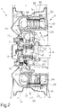
- figure 2 illustrates on an enlarged scale the driving wheel unit of figure 1.
- With reference to figures 1 and 2, there is indicated as a whole by 1 a driving wheel unit suitable for an electric traction vehicle otherwise known and not illustrated for simplicity, provided on board with a suitable electric power supply also of a known type and not illustrated for simplicity, for example batteries. The
unit 1 comprises a stub axle 2 and ahub 3, both of a known type, on which, according to the invention, are fitted respectively astator 4 and arotor 5 of anelectric motor 6, of a generally known type. The stub axle 2 is joined in a known manner to asuspension 7 of the vehicle, which in the non-limitative example illustrated is of the rigid axle type, and comprises anaxle 8 which has stub axle 2 joined integrally to it, and a shock absorber 9 joined to thebody 10 of the vehicle and to theaxle 8. It is obvious that, according to a possible variant not illustrated, thewheel unit 1 can also be supported by an independent type wheel suspension, for example the "McPherson" type, by simply joining the stub axle 2 in a known manner directly to the suspension upright, in turn joined to a typical shock absorber 9. - The stub axle 2 supports the
hub 3 idle in a known manner, for example by a roller bearing 11 fastened axially against ashoulder 12 of stub axle 2 by anut 13. Thehub 3 in turn supports, in a known manner, awheel 14 of any known type commonly used on road vehicles. In particular, thewheel 14 is fixed by means ofbolts 15 and aflange 16 to thehub 3, which is provided as part, and on the outside periphery, of a knownbrake drum 18. Integral with stub axle 2 is mounted abrake support bracket 20, which is positioned facingflange 16 ofhub 3 and supports in a known manner respective known brake shoes 21 (only one of which is visible in figure 2) capable in use of entering into frictional contact with thedrum 18 to brake the rotation of thewheel 14 with respect the stub axle 2, and a knownhydraulic control device 22 for thebrake shoes 21, attachable in a known manner not illustrated for simplicity to the brake circuit of the vehicle. In the example, thebracket 20 is connected to theaxle 8 by means ofbolts 23. If thesuspension 7 is substituted by an independent type wheel suspension, thebracket 20 is then connected to the suspension upright or is integral thereto. - According to the invention, the
unit 1 further comprises a first enclosingelement 25 ofelectric motor 6 fixed angularly and integrally tohub 3 projecting peripherally from it in a radial direction, at least one permanent magnet 26 (in the example severalpermanent magnets 26 arranged in a ring) supported peripherally by enclosingelement 25 which, together with the magnet(s) 26, therefore defines therotor 5, a second enclosingelement 28 positioned coaxially with and facingelement 25 and connected integrally with the stub axle 2, and at least onecoil 29 of a known type (in the exampleseveral coils 29 arranged in a ring) connectable in a known manner not illustrated for simplicity with the said electric power supply and supported integrally byelement 28 which, together with the coil(s) 29, thus defines thestator 4. -
Elements edges 31,32 cooperate with each other without touching to define betweenelements motor 6. - In
particular element 25 comprises a semi-toroidal element 33 of pressed sheet metal joined integrally towheel hub 3 onbrake drum 18, and anannular element 34 supporting themagnets 26 and positioned inside the semi-toroidal element 33 partially projecting outside it in an axial direction with aportion 35 thereof of smaller diameter joined to alateral wall 36 radially external to semi-torioidal element 33. One end of thelateral wall 36 is provided radially outwards with arim 40 which, together with projectingpart 35 ofelement 34, separated from the rest ofelement 34 by anannular channel 41, delimits the said edge 31 of semi-enclosure 25, which thus has an overall shape conjugate with that ofedge 32, which in radial section is substantially Z-shaped andfaces rim 40 radially external thereto and to projectingportion 35 ofelement 34, thus creating a sinuous labyrinth seal betweenelements - Enclosing
element 28 is in radial section substantially J-shaped in a position parallel with the wheel axle and, in the example, is obtained as part ofbrake support bracket 20 on the external periphery thereof. Thestator 4 androtor 5 are dimensioned with maximum external diameters which enable them to be housed entirely inside thewheel 14. Consequently, in use, theunit 1 can be fitted with a standard wheel and perform all the functions of a normal driving wheel unit, including that of braking thewheel 14, in the example by means of a braking device with a known drum already in general use. When current is supplied to the coil(s) 29, a rotating magnetic field is produced which acts onmagnets 26 rotating therotor 5 with respect to thestator 4. Motion is thus also transmitted to thehub 3 driving thewheel 14 without the need for mechanical transmission. - From what has been described, the advantages of the invention are evident. An integrated driving wheel unit of compact dimensions and great simplicity is obtained. It can be produced largely with standard components and is also fitted with braking devices. In particular, the cost of such a unit can be very low, since the
electric motor 6 is integrated into the wheel unit simply by attaching to the periphery of otherwise standard parts, such ashub 3 andbrake support bracket 20, two semi-enclosures one of which supports the elements of the stator and the other those of the rotor.
Claims (5)
- A driving wheel unit, suitable for an electric traction vehicle, of the type comprising a stub axle joined to a wheel suspension of the vehicle and a wheel hub mounted idle on the stub axle and capable of being fitted angularly and integrally with a vehicle wheel, characterised by the fact that it further comprises a first enclosing element fixed angularly and integrally to the hub and peripherally projecting from it in a radial direction, at least one permanent magnet supported peripherally by said first enclosing element in such a manner as to define thereby the rotor of an electric motor, and a stator of an electric motor connected integrally with the stub axle and comprising at least one coil connectable with a source of electric power, and a second enclosing element coaxial with and facing the first and supporting peripherally said coil.
- A driving wheel unit according to claim 1, characterised by the fact that said first and second enclosing elements are both cup-shaped positioned with their concavities facing each other and each has a respective radially external front peripheral edge; said edges cooperate with each other to define, between said first and second enclosing elements, a labyrinth seal.
- A driving wheel unit according to claim 2, characterised by the fact that said first enclosing element comprises a semi-toroidal element of pressed sheet metal joined integrally to said wheel hub, on a brake drum thereof, and an annular element supporting said permanent magnet and positioned inside the semi-toroidal element, with a portion thereof of smaller diameter partially projection from it in an axial direction, joined to a lateral wall radially external to the semi-toroidal element; one end of said lateral wall of the latter, provided with a rim, and said projecting portion of smaller diameter of said annular element, separated from the rest of the element by an annular channel, defining said peripheral front edge of the said enclosing element.
- A driving wheel unit according to claim 3, characterised by the fact that said second enclosing element is in radial section substantially J-shaped in a position parallel with the wheel axle and is obtained as part, and on the external periphery, of a brake support bracket integral with the stub axle; said peripheral front edge of the second enclosing element being in radial section substantially Z-shaped and being positioned radially facing the exterior of said rim of the edge of the lateral wall of said semi-toroidal element and said projecting portion of smaller diameter of said annular element.
- A driving wheel unit suitable for an electric traction vehicle, of the type comprising a wheel hub, a brake drum, means of braking capable of cooperating with the brake drum, and an electric motor comprising in turn a stator and a rotor, characterised by the fact that said stator supports said braking means directly and by the fact that said hub is comprised of the rotor of the electric motor, said rotor being obtained as part of the brake drum and supporting respective permanent magnets of the electric motor, while the respective coils of the electric motor are supported by the stator.
Applications Claiming Priority (2)
| Application Number | Priority Date | Filing Date | Title |
|---|---|---|---|
| IT6803890 | 1990-12-21 | ||
| IT68038A IT1241366B (en) | 1990-12-21 | 1990-12-21 | WHEEL-MOTOR UNIT FOR AN ELECTRIC DRIVE VEHICLE |
Publications (2)
| Publication Number | Publication Date |
|---|---|
| EP0492290A1 true EP0492290A1 (en) | 1992-07-01 |
| EP0492290B1 EP0492290B1 (en) | 1996-05-08 |
Family
ID=11307372
Family Applications (1)
| Application Number | Title | Priority Date | Filing Date |
|---|---|---|---|
| EP91121282A Expired - Lifetime EP0492290B1 (en) | 1990-12-21 | 1991-12-11 | Driving wheel unit for an electric traction vehicle |
Country Status (3)
| Country | Link |
|---|---|
| EP (1) | EP0492290B1 (en) |
| DE (1) | DE69119379T2 (en) |
| IT (1) | IT1241366B (en) |
Cited By (16)
| Publication number | Priority date | Publication date | Assignee | Title |
|---|---|---|---|---|
| EP0579084A1 (en) * | 1992-07-17 | 1994-01-19 | Siemens Aktiengesellschaft | Driving motor |
| US5327034A (en) * | 1992-07-14 | 1994-07-05 | Hydro-Quebec | Electrically motorized wheel assembly |
| US5412269A (en) * | 1993-06-17 | 1995-05-02 | Hydro-Quebec | Electrically motorized wheel assembly provided with a peripheral filler |
| FR2763284A1 (en) * | 1997-05-16 | 1998-11-20 | Conception & Dev Michelin Sa | PACKAGE INCLUDING A WHEEL AND INTEGRATED WHEEL SUSPENSION |
| AT405390B (en) * | 1997-03-19 | 1999-07-26 | Abb Daimler Benz Transp | ELECTRIC MOTOR WHEEL DRIVE FOR A VEHICLE WHEEL |
| US6343554B1 (en) | 1998-03-20 | 2002-02-05 | Bombardier Transportation Gmbh | Vehicle wheel, in particular for a low-platform vehicle |
| WO2003055712A1 (en) * | 2002-01-04 | 2003-07-10 | Sascha Mantovani | Electric motor with the rotor connected to the member that is to be rotated |
| WO2005000621A1 (en) * | 2003-06-25 | 2005-01-06 | Toyota Jidosha Kabushiki Kaisha | Suspension system for suspending a wheel having a motor therein |
| US6943478B2 (en) | 2003-11-14 | 2005-09-13 | Dura-Trac Motors, Inc. | Brushless permanent magnet wheel motor with variable axial rotor/stator alignment |
| US7350605B2 (en) * | 2003-09-04 | 2008-04-01 | Toyota Jidosha Kabushiki Kaisha | In-wheel motor capable of efficiently cooling electric motor and reduction gear |
| WO2008036202A3 (en) * | 2006-09-20 | 2008-07-03 | Harry K James | Direct drive electric traction motor |
| WO2013004410A1 (en) * | 2011-07-07 | 2013-01-10 | Schaeffler Technologies AG & Co. KG | Stator retaining plate having a brake anchor plate function |
| WO2013180663A3 (en) * | 2012-05-29 | 2014-03-06 | ELAPHE pogonske tehnologije, d.o.o. | Simple and accurate to assemble in-wheel electric motor |
| WO2019078217A1 (en) * | 2017-10-17 | 2019-04-25 | Ntn株式会社 | Vehicle power device |
| WO2019078216A1 (en) * | 2017-10-17 | 2019-04-25 | Ntn株式会社 | POWER DEVICE FOR VEHICLE AND BEARING DEVICE WITH GENERATOR |
| US11447003B2 (en) | 2017-10-17 | 2022-09-20 | Ntn Corporation | Vehicle power device and wheel bearing device with generator |
Families Citing this family (1)
| Publication number | Priority date | Publication date | Assignee | Title |
|---|---|---|---|---|
| IT202200008264A1 (en) * | 2022-04-27 | 2023-10-27 | Ferrari Spa | WHEEL DEVICE WITH INTEGRATED ELECTRIC MOTOR FOR A MOTOR VEHICLE |
Citations (5)
| Publication number | Priority date | Publication date | Assignee | Title |
|---|---|---|---|---|
| DE201263C (en) * | ||||
| US2150833A (en) * | 1937-11-30 | 1939-03-14 | Wayne A Hockett | Motor wheel unit |
| US2581551A (en) * | 1948-04-14 | 1952-01-08 | George M Myrmirides | Means for powering vehicles |
| FR2561593A1 (en) * | 1984-03-26 | 1985-09-27 | Bruyant Guy | Electric drive wheel |
| EP0337032A1 (en) * | 1988-03-29 | 1989-10-18 | Nippon Steel Corporation | Electric vehicle |
-
1990
- 1990-12-21 IT IT68038A patent/IT1241366B/en active IP Right Grant
-
1991
- 1991-12-11 DE DE69119379T patent/DE69119379T2/en not_active Expired - Fee Related
- 1991-12-11 EP EP91121282A patent/EP0492290B1/en not_active Expired - Lifetime
Patent Citations (5)
| Publication number | Priority date | Publication date | Assignee | Title |
|---|---|---|---|---|
| DE201263C (en) * | ||||
| US2150833A (en) * | 1937-11-30 | 1939-03-14 | Wayne A Hockett | Motor wheel unit |
| US2581551A (en) * | 1948-04-14 | 1952-01-08 | George M Myrmirides | Means for powering vehicles |
| FR2561593A1 (en) * | 1984-03-26 | 1985-09-27 | Bruyant Guy | Electric drive wheel |
| EP0337032A1 (en) * | 1988-03-29 | 1989-10-18 | Nippon Steel Corporation | Electric vehicle |
Cited By (27)
| Publication number | Priority date | Publication date | Assignee | Title |
|---|---|---|---|---|
| US5327034A (en) * | 1992-07-14 | 1994-07-05 | Hydro-Quebec | Electrically motorized wheel assembly |
| US5355039A (en) * | 1992-07-14 | 1994-10-11 | Hydro-Quebec | Electrically motorized wheel assembly |
| US5438228A (en) * | 1992-07-14 | 1995-08-01 | Hydro-Quebec | Electrically motorized wheel assembly |
| EP0579084A1 (en) * | 1992-07-17 | 1994-01-19 | Siemens Aktiengesellschaft | Driving motor |
| US5412269A (en) * | 1993-06-17 | 1995-05-02 | Hydro-Quebec | Electrically motorized wheel assembly provided with a peripheral filler |
| AT405390B (en) * | 1997-03-19 | 1999-07-26 | Abb Daimler Benz Transp | ELECTRIC MOTOR WHEEL DRIVE FOR A VEHICLE WHEEL |
| FR2763284A1 (en) * | 1997-05-16 | 1998-11-20 | Conception & Dev Michelin Sa | PACKAGE INCLUDING A WHEEL AND INTEGRATED WHEEL SUSPENSION |
| US6113119A (en) * | 1997-05-16 | 2000-09-05 | Conception Et Developpement Michelin S.A. | Assembly comprising a wheel and a suspension integrated into the wheel |
| US6343554B1 (en) | 1998-03-20 | 2002-02-05 | Bombardier Transportation Gmbh | Vehicle wheel, in particular for a low-platform vehicle |
| WO2003055712A1 (en) * | 2002-01-04 | 2003-07-10 | Sascha Mantovani | Electric motor with the rotor connected to the member that is to be rotated |
| US7735588B2 (en) | 2003-06-25 | 2010-06-15 | Toyota Jidosha Kabushiki Kaisha | Suspension system for suspending a wheel having a motor therein |
| KR100844091B1 (en) * | 2003-06-25 | 2008-07-04 | 도요다 지도샤 가부시끼가이샤 | Suspension systtem for suspending a wheel having a motor therein |
| CN100575134C (en) * | 2003-06-25 | 2009-12-30 | 丰田自动车株式会社 | Suspension system for suspending a wheel with an electric motor inside |
| WO2005000621A1 (en) * | 2003-06-25 | 2005-01-06 | Toyota Jidosha Kabushiki Kaisha | Suspension system for suspending a wheel having a motor therein |
| US7350605B2 (en) * | 2003-09-04 | 2008-04-01 | Toyota Jidosha Kabushiki Kaisha | In-wheel motor capable of efficiently cooling electric motor and reduction gear |
| US6943478B2 (en) | 2003-11-14 | 2005-09-13 | Dura-Trac Motors, Inc. | Brushless permanent magnet wheel motor with variable axial rotor/stator alignment |
| US7042128B2 (en) | 2003-11-14 | 2006-05-09 | Dura-Trac Motors, Inc. | Brushless permanent magnet wheel motor with variable axial rotor/stator alignment |
| WO2008036202A3 (en) * | 2006-09-20 | 2008-07-03 | Harry K James | Direct drive electric traction motor |
| US7658251B2 (en) | 2006-09-20 | 2010-02-09 | James Harry K | Direct drive electric traction motor |
| WO2013004410A1 (en) * | 2011-07-07 | 2013-01-10 | Schaeffler Technologies AG & Co. KG | Stator retaining plate having a brake anchor plate function |
| WO2013180663A3 (en) * | 2012-05-29 | 2014-03-06 | ELAPHE pogonske tehnologije, d.o.o. | Simple and accurate to assemble in-wheel electric motor |
| US9862264B2 (en) | 2012-05-29 | 2018-01-09 | Elaphe Pogonoske Tehnologije, D.O.O. | In-wheel electric motor |
| EP2855183B1 (en) * | 2012-05-29 | 2018-08-01 | Elaphe Pogonske Tehnologije D.o.o. | Simple and accurate to assemble in-wheel electric motor |
| WO2019078217A1 (en) * | 2017-10-17 | 2019-04-25 | Ntn株式会社 | Vehicle power device |
| WO2019078216A1 (en) * | 2017-10-17 | 2019-04-25 | Ntn株式会社 | POWER DEVICE FOR VEHICLE AND BEARING DEVICE WITH GENERATOR |
| JP2019073170A (en) * | 2017-10-17 | 2019-05-16 | Ntn株式会社 | Vehicle power device |
| US11447003B2 (en) | 2017-10-17 | 2022-09-20 | Ntn Corporation | Vehicle power device and wheel bearing device with generator |
Also Published As
| Publication number | Publication date |
|---|---|
| IT9068038A0 (en) | 1990-12-21 |
| EP0492290B1 (en) | 1996-05-08 |
| IT9068038A1 (en) | 1992-06-22 |
| DE69119379D1 (en) | 1996-06-13 |
| DE69119379T2 (en) | 1996-10-10 |
| IT1241366B (en) | 1994-01-10 |
Similar Documents
| Publication | Publication Date | Title |
|---|---|---|
| EP0492290B1 (en) | Driving wheel unit for an electric traction vehicle | |
| CN101400537B (en) | Linear drive travel system and vehicle | |
| US5600191A (en) | Driving assembly for motor wheels | |
| US6590306B2 (en) | Electric motor driven wheel | |
| US7528518B2 (en) | In-wheel motor | |
| KR102708798B1 (en) | In-wheel working device | |
| CA2743970C (en) | Electric motor wheel assembly | |
| EP0860626A3 (en) | Connection between a wheel hub bearing unit and brake rotor | |
| KR970043517A (en) | Drive of front-loading washing machine | |
| DE60235621D1 (en) | ELECTRIC WHEEL HUB DRIVE SYSTEM | |
| KR20100083521A (en) | Wheel structure for mounting in wheel motor | |
| US5219050A (en) | Eddy current braking apparatus | |
| US12533944B2 (en) | In-wheel motor | |
| US12485742B2 (en) | Wheel device with integrated electric motor for a motor vehicle | |
| JP3094345B2 (en) | Wheel motor | |
| JP2023163148A5 (en) | ||
| JPH10305735A (en) | Wheel-in motor | |
| JP2007153266A (en) | In-wheel motor | |
| JPH09275672A (en) | Eddy current retarder | |
| CN105228844B (en) | Driving wheel for vehicle | |
| JPH0237027A (en) | Electric car | |
| JPH07131961A (en) | Electric motor and its control device | |
| JP7718303B2 (en) | Drive unit | |
| JPH106947A (en) | Retarder braking system for trailers | |
| JPH0625722Y2 (en) | Electromagnetic clutch |
Legal Events
| Date | Code | Title | Description |
|---|---|---|---|
| PUAI | Public reference made under article 153(3) epc to a published international application that has entered the european phase |
Free format text: ORIGINAL CODE: 0009012 |
|
| AK | Designated contracting states |
Kind code of ref document: A1 Designated state(s): DE ES FR GB SE |
|
| 17P | Request for examination filed |
Effective date: 19921221 |
|
| 17Q | First examination report despatched |
Effective date: 19941011 |
|
| GRAH | Despatch of communication of intention to grant a patent |
Free format text: ORIGINAL CODE: EPIDOS IGRA |
|
| GRAA | (expected) grant |
Free format text: ORIGINAL CODE: 0009210 |
|
| AK | Designated contracting states |
Kind code of ref document: B1 Designated state(s): DE ES FR GB SE |
|
| PG25 | Lapsed in a contracting state [announced via postgrant information from national office to epo] |
Ref country code: ES Free format text: THE PATENT HAS BEEN ANNULLED BY A DECISION OF A NATIONAL AUTHORITY Effective date: 19960508 |
|
| REF | Corresponds to: |
Ref document number: 69119379 Country of ref document: DE Date of ref document: 19960613 |
|
| ET | Fr: translation filed | ||
| PLBE | No opposition filed within time limit |
Free format text: ORIGINAL CODE: 0009261 |
|
| STAA | Information on the status of an ep patent application or granted ep patent |
Free format text: STATUS: NO OPPOSITION FILED WITHIN TIME LIMIT |
|
| 26N | No opposition filed | ||
| PGFP | Annual fee paid to national office [announced via postgrant information from national office to epo] |
Ref country code: GB Payment date: 20011122 Year of fee payment: 11 |
|
| PGFP | Annual fee paid to national office [announced via postgrant information from national office to epo] |
Ref country code: SE Payment date: 20011126 Year of fee payment: 11 |
|
| REG | Reference to a national code |
Ref country code: GB Ref legal event code: IF02 |
|
| PG25 | Lapsed in a contracting state [announced via postgrant information from national office to epo] |
Ref country code: GB Free format text: LAPSE BECAUSE OF NON-PAYMENT OF DUE FEES Effective date: 20021211 |
|
| PG25 | Lapsed in a contracting state [announced via postgrant information from national office to epo] |
Ref country code: SE Free format text: LAPSE BECAUSE OF NON-PAYMENT OF DUE FEES Effective date: 20021212 |
|
| EUG | Se: european patent has lapsed | ||
| GBPC | Gb: european patent ceased through non-payment of renewal fee | ||
| PGFP | Annual fee paid to national office [announced via postgrant information from national office to epo] |
Ref country code: FR Payment date: 20041028 Year of fee payment: 14 |
|
| PGFP | Annual fee paid to national office [announced via postgrant information from national office to epo] |
Ref country code: DE Payment date: 20041230 Year of fee payment: 14 |
|
| PG25 | Lapsed in a contracting state [announced via postgrant information from national office to epo] |
Ref country code: DE Free format text: LAPSE BECAUSE OF NON-PAYMENT OF DUE FEES Effective date: 20060701 |
|
| PG25 | Lapsed in a contracting state [announced via postgrant information from national office to epo] |
Ref country code: FR Free format text: LAPSE BECAUSE OF NON-PAYMENT OF DUE FEES Effective date: 20060831 |
|
| REG | Reference to a national code |
Ref country code: FR Ref legal event code: ST Effective date: 20060831 |