EP0492127A2 - Bushing for switching devices insulated by pressure gas - Google Patents
Bushing for switching devices insulated by pressure gas Download PDFInfo
- Publication number
- EP0492127A2 EP0492127A2 EP91119617A EP91119617A EP0492127A2 EP 0492127 A2 EP0492127 A2 EP 0492127A2 EP 91119617 A EP91119617 A EP 91119617A EP 91119617 A EP91119617 A EP 91119617A EP 0492127 A2 EP0492127 A2 EP 0492127A2
- Authority
- EP
- European Patent Office
- Prior art keywords
- inner conductor
- device connection
- connection part
- current
- adapter
- Prior art date
- Legal status (The legal status is an assumption and is not a legal conclusion. Google has not performed a legal analysis and makes no representation as to the accuracy of the status listed.)
- Granted
Links
Images

Classifications
-
- H—ELECTRICITY
- H01—ELECTRIC ELEMENTS
- H01B—CABLES; CONDUCTORS; INSULATORS; SELECTION OF MATERIALS FOR THEIR CONDUCTIVE, INSULATING OR DIELECTRIC PROPERTIES
- H01B17/00—Insulators or insulating bodies characterised by their form
- H01B17/26—Lead-in insulators; Lead-through insulators
Definitions
- the invention relates to a bushing for pressurized gas-insulated switchgear assemblies according to the preamble of claim 1.
- Such bushings are used in gas-insulated switchgear gas-tight in the housing walls of these systems. After installing a system, it is necessary to subject the connected cables to a voltage test. It is already known that separate feedthroughs are additionally used for the testing of the cables, which are externally connected to a grounding rail in three phases and represent part of the inner grounding switch through contacts placed inside the system. With this construction, the outer earthing bar can be removed, the internal switch can be switched into the attached contacts inside, and a cable test can be carried out in this switching state. In this context, removing the external earth connection can result in a safety hazard. Otherwise, the arrangement described above is very expensive and the assignment is difficult to recognize.
- the invention specified in claim 1 is therefore based on the problem of creating an implementation that allows a simple test of the cable connected to the implementation while increasing the security and reducing the parts required for this.
- standard plugs and end closure fittings should be able to be connected to the bushing without great effort.
- a lateral adapter is introduced by a slight spatial enlargement of the bushing, the inner conductor of which can be connected in a simple and electrically tight manner to the current-carrying inner conductor of the bushing on the one hand and on the other hand a connection for testing the cable provides.
- a device connection part 1 is fastened with its fastening flange 2 to a switchgear assembly 17 .
- a section 4 adjoins the fastening flange 2 and is predominantly cylindrical. In the extension of this section 4 , a conical section 3 is arranged, which serves to connect a plug or a cable set (not shown).
- a current-carrying inner conductor 5 designed as a lead-through bolt is inserted axially in the device connection part 1 .
- section 4 there is a lateral opening 6 which serves to accommodate an adapter 7 .
- This adapter 7 contains an inner conductor 8 which is designed as a threaded stud bolt 12, 13, 14 .
- an externally threaded part is connected to the shoulder 12 of the threaded stud bolt 13 and on the other hand an internal thread part 14 .
- the adapter 7 has a bottom 10 with an axial bore 11 , which is designed such that the shoulder 12 of the threaded stud bolt 12, 13, 14 has a firm seat in the ground 10 of the adapter 7 has.
- the external thread part 13 engages in a threaded blind hole 9 of the current-carrying inner conductor 5
- the internal thread part 14 which has the same internal diameter as the external diameter of the external thread part 13 , serves to receive an external thread 16 of an insulating plug 15 .
- the lateral opening 6 of the device connection part 1 has a blind hole-like shape 19 which merges into an axial bore 20 in the region of the extension 12 .
- the design of the adapter 7 as a hollow cone means that the internal thread part 14 also has an external conical shape 21 which is adapted to the internal cone of the adapter 7 .
- the cone of the adapter 7 is guided up to the current-carrying inner conductor 5 of the device connection part 1 .
- a continuous threaded bore 22 is made in the current-carrying inner conductor 5 in order to be able to accommodate the elongated external thread part 13 .
- a double cone 23 is screwed into the current-carrying conductor 5 as a cable test connection.
- the double cone 23 consists of silicone rubber and has a shoulder bolt 24 made of electrolytic copper.
- the shoulder bolt 24 has a threaded part 25 on the side facing the current-carrying inner conductor 5 and a threaded part 26 on the side facing away from the current-carrying inner conductor 5 for receiving a wing nut 27 .
- the shoulder bolt 24 has a driving ring 28 which is screwed onto the shoulder bolt 24 and is cast by the silicone of the double cone 23 .
- the opening 6 in the device connection part 1 is closed by a molded part 29 made of insulating material.
- This molded part 29 is cast in a silicone rubber cone 30 , a driving ring 31 being provided for the silicone part (cast in the molded part 29 ).
Abstract
Description
Die Erfindung betrifft eine Durchführung für druckgasisolierte Schaltanlagen gemäß dem Oberbegriff des Anspruchs 1.The invention relates to a bushing for pressurized gas-insulated switchgear assemblies according to the preamble of
Derartige Durchführungen werden in druckgasisolierten Schaltanlagen gasdicht in den Gehäusewandungen dieser Anlagen eingesetzt. Nach der Installation einer Anlage ist es erforderlich, die angeschlossenen Kabel einer Spannungsprüfung zu unterziehen. Hierbei ist es bereits bekannt, daß für die Prüfung der Kabel gesonderte Durchführungen zusätzlich eingesetzt werden, welche außen mit einer Erdungsschiene dreiphasig verbunden sind und durch im Innenraum der Anlage aufgesetzte Kontakte einen Teil des inneren Erdungsschalters darstellen. Mit diesem Aufbau kann die äußere Erdungsschiene entfernt werden, der innenliegende Schalter in die aufgesetzten Kontakte im Inneren einschalten, wobei in diesem Schaltzustand eine Kabelprüfung erfolgen kann. In diesem Zusammenhang kann durch das Entfernen der äußeren Erdverbindung ein die Sicherheit gefährdeter Zustand entstehen. Im übrigen ist die zuvor beschriebene Anordnung sehr kostenaufwendig und die Zuordnung schlecht erkennbar.Such bushings are used in gas-insulated switchgear gas-tight in the housing walls of these systems. After installing a system, it is necessary to subject the connected cables to a voltage test. It is already known that separate feedthroughs are additionally used for the testing of the cables, which are externally connected to a grounding rail in three phases and represent part of the inner grounding switch through contacts placed inside the system. With this construction, the outer earthing bar can be removed, the internal switch can be switched into the attached contacts inside, and a cable test can be carried out in this switching state. In this context, removing the external earth connection can result in a safety hazard. Otherwise, the arrangement described above is very expensive and the assignment is difficult to recognize.
Der im Anspruch 1 angegebenen Erfindung liegt daher das Problem zugrunde, eine Durchführung zu schaffen, die eine einfache Prüfung des an die Durchführung angeschlossenen Kabels bei gleichzeitiger Erhöhung der Sicherheit und Verminderung der hierfür erforderlichen Teile gestattet. Hierbei sollen handelsübliche Stecker und Endverschlußarmaturen ohne größeren Aufwand an der Durchführung angeschlossen werden können.The invention specified in
Dieses Problem wird mit den Maßnahmen des Anspruchs 1 gelöst.This problem is solved with the measures of
Mit der Erfindung wird im angegebenen Anwendungsfall erreicht, daß durch eine geringe räumliche Vergrößerung der Durchführung ein seitlicher Adapter eingebracht wird, dessen Innenleiter einerseits mit dem stromführenden Innenleiter der Durchführung auf einfache Weise und elektrisch dicht verbunden werden kann und andererseits einen Anschluß für die Prüfung des Kabels vorsieht. Mit der Adapteranordnung an der Durchführung ist nunmehr auch eine eindeutige Zuordnung zum jeweiligen Kabel sichergestellt.With the invention in the specified application it is achieved that a lateral adapter is introduced by a slight spatial enlargement of the bushing, the inner conductor of which can be connected in a simple and electrically tight manner to the current-carrying inner conductor of the bushing on the one hand and on the other hand a connection for testing the cable provides. With the adapter arrangement on the bushing, a clear assignment to the respective cable is now also ensured.
Vorteilhafte Ausgestaltungen der Erfindung sind in den Ansprüchen 2 bis 13 angegeben.Advantageous embodiments of the invention are specified in
Ein Ausführungsbeispiel der Erfindung wird anhand der Figuren 1 bis 4 erläutert. Es zeigen
- Fig. 1
- die Durchführung mit einem verschlossenen Adapter in Seitenansicht und teilweise im Schnitt
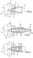
- Fig. 2
- eine weitere Ausführung der Durchführung mit verschlossenem Adapter, in Seitenansicht und teilweise im Schnitt
- Fig. 3
- die Durchführung mit einem eingeschraubten Kabelprüfanschluß in Seitenansicht und teilweise im Schnitt
- Fig. 4
- diese Durchführung mit einem eingeschraubten Verschlußstopfen, in Seitenansicht und teilweise im Schnitt.
- Fig. 1
- the implementation with a sealed adapter in side view and partly in section
- Fig. 2
- a further embodiment of the implementation with a closed adapter, in side view and partly in section
- Fig. 3
- the implementation with a screwed cable test connection in side view and partly in section
- Fig. 4
- this implementation with a screwed plug, in side view and partly in section.
Nach Fig. 1 ist ein Geräteanschlußteil 1 mit seinem Befestigungsflansch 2 an einer Schaltanlage 17 befestigt. An dem Befestigungsflansch 2 schließt sich ein Abschnitt 4 an, der vorwiegend zylindrisch ausgebildet ist. In Verlängerung dieses Abschnitts 4 ist ein konischer Abschnitt 3 angeordnet, der zum Anschluß eines Steckers oder einer Kabelgarnitur (nicht dargestellt) dient. Ein als Durchführungsbolzen ausgebildeter und stromführender Innenleiter 5 ist axial im Geräteanschlußteil 1 eingesetzt. Im Abschnitt 4 befindet sich eine seitliche öffnung 6, die der Aufnahme eines Adapters 7 dient. Dieser Adapter 7 enthält einen Innenleiter 8, der als Gewindeansatzbolzen 12,13,14 ausgebildet ist. An den Ansatz 12 des Gewindeansatzbolzens schließen sich einerseits ein Außengewindeteil 13 und andererseits ein Innengewindeteil 14 an. Um den Gewindeansatzbolzen 12,13,14 fachgerecht im Adapter 7 unterbringen zu können, besitzt der Adapter 7 einen Boden 10 mit einer axialen Bohrung 11, die so beschaffen ist, daß der Ansatz 12 des Gewindeansatzbolzens 12,13,14 einen festen Sitz im Boden 10 des Adapters 7 hat. Das Außengewindeteil 13 greift in eine Gewindesacklochbohrung 9 des stromführenden Innenleiters 5 ein, während daß Innengewindeteil 14, das den gleichen Innendurchmesser wie den Außendurchmesser des Außengewindeteils 13 aufweist, der Aufnahme eines Außengewindes 16 eines Isolierpfropfens 15 dient. Die seitliche öffnung 6 des Geräteanschlußteils 1 weist eine sacklochartige Form 19 auf, die im Bereich des Ansatzes 12 in eine axiale Bohrung 20 übergeht. Die Gestaltung des Adapters 7 als hohler Konus bringt es mit sich, daß das Innengewindeteil 14 ebenfalls eine an den Innenkonus des Adapters 7 angepaßte außenkonische Form 21 aufweist.1, a
Nach Fig. 2 ist der Konus des Adapters 7 bis an den stromführenden Innenleiter 5 des Geräteanschlußteils 1 geführt. Im stromführenden Innenleiter 5 ist eine durchgehende Gewindebohrung 22 eingebracht, um das verlängerte Außengewindeteil 13 aufnehmen zu können.2, the cone of the
Nach Fig. 3 ist ein Doppelkonus 23 als Kabelprüfanschluß in den stromführenden Leiter 5 eingeschraubt. Der Doppelkonus 23 besteht aus Silikonkautschuk und besitzt einen Ansatzbolzen 24 aus Elektrolytkupfer. Der Ansatzbolzen 24 besitzt an der zum stromführenden Innenleiter 5 gewandten Seite ein Gewindeteil 25 und an der vom stromführenden Innenleiter 5 abgewandten Seite ein Gewindeteil 26 zur Aufnahme einer Flügelmutter 27. Der Ansatzbolzen 24 weist einen Mitnahmering 28 auf, der am Ansatzbolzen 24 angedreht und vom Silikon des Doppelkonus 23 umgossen ist.3, a
Nach Herausnahme des Doppelkonus 23 nach Fig. 3 wird die Öffnung 6 im Geräteanschlußteil 1 durch ein Formteil 29 aus Isolierstoff verschlossen. Dieses Formteil 29 ist in einem Silikonkautschukkonus 30 eingegossen, wobei ein Mitnahmering 31 für das Silikonteil (im Formteil 29 gegossen) vorgesehen ist.After removing the
Claims (13)
Applications Claiming Priority (2)
| Application Number | Priority Date | Filing Date | Title |
|---|---|---|---|
| DE4040903 | 1990-12-20 | ||
| DE4040903A DE4040903A1 (en) | 1990-12-20 | 1990-12-20 | PERFORMANCE FOR GAS INSULATED SWITCHGEAR |
Publications (3)
| Publication Number | Publication Date |
|---|---|
| EP0492127A2 true EP0492127A2 (en) | 1992-07-01 |
| EP0492127A3 EP0492127A3 (en) | 1993-02-24 |
| EP0492127B1 EP0492127B1 (en) | 1995-05-24 |
Family
ID=6420858
Family Applications (1)
| Application Number | Title | Priority Date | Filing Date |
|---|---|---|---|
| EP91119617A Expired - Lifetime EP0492127B1 (en) | 1990-12-20 | 1991-11-18 | Bushing for switching devices insulated by pressure gas |
Country Status (3)
| Country | Link |
|---|---|
| EP (1) | EP0492127B1 (en) |
| DE (2) | DE4040903A1 (en) |
| ES (1) | ES2074634T3 (en) |
Cited By (1)
| Publication number | Priority date | Publication date | Assignee | Title |
|---|---|---|---|---|
| CN105810372A (en) * | 2016-04-29 | 2016-07-27 | 句容华源电器设备有限公司 | Insulating plug capable of measuring humidity |
Citations (3)
| Publication number | Priority date | Publication date | Assignee | Title |
|---|---|---|---|---|
| DE1023807B (en) * | 1954-08-31 | 1958-02-06 | Westinghouse Electric Corp | Multiple implementation for gas-tight sealed electrical devices and machines |
| DE1076214B (en) * | 1958-11-18 | 1960-02-25 | Liebknecht Transformat | Implementation for electrical devices |
| EP0147979A1 (en) * | 1983-12-14 | 1985-07-10 | Raychem Limited | High voltage connector |
-
1990
- 1990-12-20 DE DE4040903A patent/DE4040903A1/en not_active Withdrawn
-
1991
- 1991-11-18 ES ES91119617T patent/ES2074634T3/en not_active Expired - Lifetime
- 1991-11-18 EP EP91119617A patent/EP0492127B1/en not_active Expired - Lifetime
- 1991-11-18 DE DE59105585T patent/DE59105585D1/en not_active Expired - Fee Related
Patent Citations (3)
| Publication number | Priority date | Publication date | Assignee | Title |
|---|---|---|---|---|
| DE1023807B (en) * | 1954-08-31 | 1958-02-06 | Westinghouse Electric Corp | Multiple implementation for gas-tight sealed electrical devices and machines |
| DE1076214B (en) * | 1958-11-18 | 1960-02-25 | Liebknecht Transformat | Implementation for electrical devices |
| EP0147979A1 (en) * | 1983-12-14 | 1985-07-10 | Raychem Limited | High voltage connector |
Cited By (1)
| Publication number | Priority date | Publication date | Assignee | Title |
|---|---|---|---|---|
| CN105810372A (en) * | 2016-04-29 | 2016-07-27 | 句容华源电器设备有限公司 | Insulating plug capable of measuring humidity |
Also Published As
| Publication number | Publication date |
|---|---|
| DE59105585D1 (en) | 1995-06-29 |
| EP0492127B1 (en) | 1995-05-24 |
| EP0492127A3 (en) | 1993-02-24 |
| DE4040903A1 (en) | 1992-06-25 |
| ES2074634T3 (en) | 1995-09-16 |
Similar Documents
| Publication | Publication Date | Title |
|---|---|---|
| EP2431982B1 (en) | Plugable feedthrough and high voltage assembly with such a feedthrough | |
| DE1241885B (en) | Connection device for electrical cables | |
| EP0919076A1 (en) | Encapsulated gas isolated high voltage installation with a partitioned connector component | |
| EP1283564B1 (en) | Coupling member for a schielded electrical cable and process for its installation on a cable | |
| EP0492127B1 (en) | Bushing for switching devices insulated by pressure gas | |
| DE4008328C2 (en) | ||
| EP0678953B1 (en) | Cable termination for a metal-clad gas-insulated high voltage switch installation | |
| DE3041337A1 (en) | HV cable connector for mining equipment - has identical components for each cable end and interfacing adaptor | |
| DE3508329A1 (en) | Plug-in cable fitting | |
| DE19612535C1 (en) | Fuse connection device for compact network stations | |
| DE3538193C2 (en) | ||
| DE3436084C2 (en) | ||
| DE2145786A1 (en) | Removable circuit breaker for encapsulated systems | |
| DE975904C (en) | Single-conductor current transformer with a housing that can be plugged onto a busbar | |
| EP0110008A2 (en) | Connection device with a fuse for enclosed medium voltage switchgear | |
| DE3538210A1 (en) | Plug connection on a T-plug for screened heavy-current cables | |
| DE1615902C3 (en) | High-voltage distribution system encapsulated in insulating material | |
| DE3619789C1 (en) | Connecting device which can be connected to a bolt | |
| DE4135390C1 (en) | Current connecting plug for power supply - has rotatable fixing ring on housing allowing connection to housing of cooperating socket | |
| DE1218575B (en) | Terminal box with flashover protection for electrical machines | |
| EP0478098B1 (en) | Gas insulated medium voltage switchgear with feed-troughs for realising an external earthing connection | |
| DE2659234A1 (en) | CABLE ACCESSORY FOR CONNECTING A SHIELDED, PLASTIC INSULATED POWERFUL CABLE TO AN ELECTRICAL DEVICE | |
| DE19845005C1 (en) | Sleeve body for covering cable core end sections | |
| DE3214474A1 (en) | Switch panel filled with insulating gas | |
| DE202007018438U1 (en) | Plant container for a switchgear and associated ring cable branch |
Legal Events
| Date | Code | Title | Description |
|---|---|---|---|
| PUAI | Public reference made under article 153(3) epc to a published international application that has entered the european phase |
Free format text: ORIGINAL CODE: 0009012 |
|
| AK | Designated contracting states |
Kind code of ref document: A2 Designated state(s): DE ES FR IT |
|
| PUAL | Search report despatched |
Free format text: ORIGINAL CODE: 0009013 |
|
| AK | Designated contracting states |
Kind code of ref document: A3 Designated state(s): DE ES FR IT |
|
| 17P | Request for examination filed |
Effective date: 19930122 |
|
| 17Q | First examination report despatched |
Effective date: 19940823 |
|
| GRAA | (expected) grant |
Free format text: ORIGINAL CODE: 0009210 |
|
| AK | Designated contracting states |
Kind code of ref document: B1 Designated state(s): DE ES FR IT |
|
| REF | Corresponds to: |
Ref document number: 59105585 Country of ref document: DE Date of ref document: 19950629 |
|
| ITF | It: translation for a ep patent filed |
Owner name: ING. C. GREGORJ S.P.A. |
|
| ET | Fr: translation filed | ||
| REG | Reference to a national code |
Ref country code: ES Ref legal event code: FG2A Ref document number: 2074634 Country of ref document: ES Kind code of ref document: T3 |
|
| PLBI | Opposition filed |
Free format text: ORIGINAL CODE: 0009260 |
|
| PLBQ | Unpublished change to opponent data |
Free format text: ORIGINAL CODE: EPIDOS OPPO |
|
| 26 | Opposition filed |
Opponent name: FRITZ DRIESCHER KG Effective date: 19960226 |
|
| PLBF | Reply of patent proprietor to notice(s) of opposition |
Free format text: ORIGINAL CODE: EPIDOS OBSO |
|
| PLBF | Reply of patent proprietor to notice(s) of opposition |
Free format text: ORIGINAL CODE: EPIDOS OBSO |
|
| PGFP | Annual fee paid to national office [announced via postgrant information from national office to epo] |
Ref country code: ES Payment date: 19981111 Year of fee payment: 8 |
|
| PLBQ | Unpublished change to opponent data |
Free format text: ORIGINAL CODE: EPIDOS OPPO |
|
| PLAB | Opposition data, opponent's data or that of the opponent's representative modified |
Free format text: ORIGINAL CODE: 0009299OPPO |
|
| R26 | Opposition filed (corrected) |
Opponent name: FRITZ DRIESCHER KG SPEZIALFABRIK FUER ELEKTRIZITAE Effective date: 19960226 |
|
| PG25 | Lapsed in a contracting state [announced via postgrant information from national office to epo] |
Ref country code: ES Free format text: LAPSE BECAUSE OF NON-PAYMENT OF DUE FEES Effective date: 19991119 |
|
| PLBL | Opposition procedure terminated |
Free format text: ORIGINAL CODE: EPIDOS OPPC |
|
| PLBM | Termination of opposition procedure: date of legal effect published |
Free format text: ORIGINAL CODE: 0009276 |
|
| STAA | Information on the status of an ep patent application or granted ep patent |
Free format text: STATUS: OPPOSITION PROCEDURE CLOSED |
|
| 27C | Opposition proceedings terminated |
Effective date: 20001127 |
|
| PGFP | Annual fee paid to national office [announced via postgrant information from national office to epo] |
Ref country code: DE Payment date: 20031103 Year of fee payment: 13 |
|
| PGFP | Annual fee paid to national office [announced via postgrant information from national office to epo] |
Ref country code: FR Payment date: 20031107 Year of fee payment: 13 |
|
| REG | Reference to a national code |
Ref country code: ES Ref legal event code: FD2A Effective date: 20001214 |
|
| PG25 | Lapsed in a contracting state [announced via postgrant information from national office to epo] |
Ref country code: DE Free format text: LAPSE BECAUSE OF NON-PAYMENT OF DUE FEES Effective date: 20050601 |
|
| PG25 | Lapsed in a contracting state [announced via postgrant information from national office to epo] |
Ref country code: FR Free format text: LAPSE BECAUSE OF NON-PAYMENT OF DUE FEES Effective date: 20050729 |
|
| REG | Reference to a national code |
Ref country code: FR Ref legal event code: ST |
|
| PG25 | Lapsed in a contracting state [announced via postgrant information from national office to epo] |
Ref country code: IT Free format text: LAPSE BECAUSE OF NON-PAYMENT OF DUE FEES;WARNING: LAPSES OF ITALIAN PATENTS WITH EFFECTIVE DATE BEFORE 2007 MAY HAVE OCCURRED AT ANY TIME BEFORE 2007. THE CORRECT EFFECTIVE DATE MAY BE DIFFERENT FROM THE ONE RECORDED. Effective date: 20051118 |