EP0491436A2 - Matrix display device with write-in facility - Google Patents
Matrix display device with write-in facility Download PDFInfo
- Publication number
- EP0491436A2 EP0491436A2 EP91203273A EP91203273A EP0491436A2 EP 0491436 A2 EP0491436 A2 EP 0491436A2 EP 91203273 A EP91203273 A EP 91203273A EP 91203273 A EP91203273 A EP 91203273A EP 0491436 A2 EP0491436 A2 EP 0491436A2
- Authority
- EP
- European Patent Office
- Prior art keywords
- row
- elements
- storage means
- charge storage
- sensing
- Prior art date
- Legal status (The legal status is an assumption and is not a legal conclusion. Google has not performed a legal analysis and makes no representation as to the accuracy of the status listed.)
- Granted
Links
Images

Classifications
-
- G—PHYSICS
- G06—COMPUTING; CALCULATING OR COUNTING
- G06F—ELECTRIC DIGITAL DATA PROCESSING
- G06F3/00—Input arrangements for transferring data to be processed into a form capable of being handled by the computer; Output arrangements for transferring data from processing unit to output unit, e.g. interface arrangements
- G06F3/01—Input arrangements or combined input and output arrangements for interaction between user and computer
- G06F3/03—Arrangements for converting the position or the displacement of a member into a coded form
- G06F3/041—Digitisers, e.g. for touch screens or touch pads, characterised by the transducing means
- G06F3/0412—Digitisers structurally integrated in a display
-
- G—PHYSICS
- G06—COMPUTING; CALCULATING OR COUNTING
- G06F—ELECTRIC DIGITAL DATA PROCESSING
- G06F3/00—Input arrangements for transferring data to be processed into a form capable of being handled by the computer; Output arrangements for transferring data from processing unit to output unit, e.g. interface arrangements
- G06F3/01—Input arrangements or combined input and output arrangements for interaction between user and computer
- G06F3/03—Arrangements for converting the position or the displacement of a member into a coded form
- G06F3/041—Digitisers, e.g. for touch screens or touch pads, characterised by the transducing means
- G06F3/042—Digitisers, e.g. for touch screens or touch pads, characterised by the transducing means by opto-electronic means
Definitions
- This invention relates to a matrix display device for displaying information which includes optical sensing means for enabling input of information as well, for example by way of a light pen. More particularly, the invention is concerned with an active matrix liquid crystal display device comprising a display panel having an array of picture elements each comprising a liquid crystal display element and an associated switching means, sets of row and column address conductors connected to the picture elements and drive means for applying drive signals to the sets of conductors for driving the picture elements, the display panel further including an array of active addressed sensing elements each comprising a photo-sensitive element and a switching device.
- the display device consists of an active matrix liquid crystal display panel of generally conventional form having a row and column array of display elements connected to sets of row and column address conductors through respective thin film transistors (TFTs).
- TFTs thin film transistors
- the display elements are driven in normal fashion by applying a selection (gating) signal to each row conductor at a time in turn so as to turn on the TFTs of the picture elements associated with that row whereby data signals present on the column conductors are transferred to electrodes of the respective display elements in the row to produce the required display effect.
- a sensing element comprising a photodiode and a TFT, is provided for each picture element.
- the picture element TFTs, display element electrodes, the sense element TFTs and photoelectric elements, and the row and column address conductors are all formed on a common substrate of the display panel.
- the sense elements are operated in a similar fashion to the picture elements with a gating signal being applied to the TFTs of each row of sense elements in turn so as to turn those TFTs on and connect the photoelectric elements of the row of sense elements to a detection circuit which is responsive to an increase in the conductance of a photoelectric element caused by illumination from the light pen. Consequently, for an input to be detected the illumination of a sense element must coincide with the gating of the TFT of the sense element concerned.
- the display device is operated such that the display and sense functions are performed in separate frame periods.
- a basic frame interval is divided into a display frame interval, during which all rows of the picture elements are addressed with display information, followed by a light detection frame interval during which the conditions of the rows of sense elements are detected.
- a display frame interval during which all rows of the picture elements are addressed with display information
- a light detection frame interval during which the conditions of the rows of sense elements are detected.
- display and detection functions can be performed at the same time by using further sets of row and column conductors dedicated to the sense elements and separate from the row and column address conductors of the display elements so that the display and sense elements can be addressed independently of each other.
- the increase in the numbers of address conductors then required complicates fabrication and can lead to problems with yields.
- an active matrix liquid crystal display device as described in the opening paragraph which is characterised in that the sensing elements each include a charge storage means which is connected to the switching device, in that the switching devices are operable by the drive signals applied to the row and column address conductors so as to charge the charge storage means, in that the photo-sensitive element of each sensing element is arranged so as to discharge the charge storage means in response the illumination thereof, and in that the device includes detection means connected to the sensing elements for detecting periodically the state of charge of their charge storage means.
- each sensing element has in effect a sense memory function by virtue of its charge storage means.
- the state of the sensing element is changed following the operation of its switching device by the drive signals to charge its charge storage means, upon being illuminated by, for example, a light pen.
- the change in state of the sensing element can thus be detected after the event. This detection is therefore not dependent on the simultaneous illumination of the sensing element but can be carried out in a detection period to determine those sensing elements which have been subjected to illumination at some earlier time. Consequently, the possibility of illuminated sensing elements being undetected due to fast movement of the light pen is avoided.
- the drive means is preferably arranged in accordance with conventional practice to apply display data signals to the column address conductors and a selection signal to each row address conductor in turn so as to operate the switching means of the row of picture elements associated with the row address conductor to apply the data signals to their respective display elements.
- the switching devices of each row of sensing elements are preferably operable by a selection signal applied to an associated row address conductor so as to charge the charge storage means of the sensing elements according to the display data signals which are present on the associated column address conductors.
- each sensing element preferably comprises a capacitor which is connected between the switching device and a reference potential, which may be a row address conductor adjacent to that associated with the sensing element's switching device, or a source of predetermined potential comprising an auxiliary row conductor common to all sensing elements in a row.
- the charge storage means may comprise a capacitor formed separately to the photo-sensitive element or alternatively may be constituted by the self capacitance of the photo-sensitive element.
- the detection means is arranged to determine the state of the sensing elements during a display field.
- the detection means may be operable to determine the state of row of sensing elements associated with a row address conductor each time a drive signal is applied to that conductor.
- each row address period determined by the duration of a row selection signal applied by the drive means to each row address conductor may be divided into a detection interval during which the state of a sensing element associated with that row address conductor is determined followed by a drive interval during which data signals for the associated row of picture elements are applied to the column address conductors.
- the sensing elements thus may be driven at a rate corresponding to the driving of the picture elements, that is, each sensing element is driven once per display field period of the picture elements.
- the state of the sensing elements is detected at the same rate, that is once every display field period.
- the interval between driving and detecting is approximately one field period.
- the display and sense functions of the device may therefore be performed concurrently with each picture element and each sensing element being addressed once in every successive field period.
- the detection means is arranged to detect the charge state of the charge storage means of a sensing element by measuring the charging characteristic of the charge storage means in response to the application thereto of a predetermined potential. In this way, the detection of illuminated sensing elements can be accomplished in a simple and convenient manner.
- the display device is an active matrix addressed liquid crystal display device comprising a display panel, 10, having a row and column array of individually operable picture elements which consists of m rows (1 to m) with n horizontally arranged picture elements (1 to n) in each row.
- Each picture element, referenced at 12 is located at a respective intersection between crossing sets of m row address conductors 14 and n column address conductors 16. Only a few of the picture elements are shown in Figure 1, for clarity. In practice the total number of picture elements in the matrix array (m x n) may be several hundreds of thousands.
- the display device is suitable to provide a datagraphic display or a picture display.
- the display panel 10 further includes a matrix array of sensing elements 18, there being one sensing element located adjacent each picture element 12, except for the first column of picture elements, giving a high resolution sensing capability.
- Each picture element 12 comprises a switching device in the form of a thin film field effect transistor, TFT, 20 connected with a liquid crystal display element 21, the impedance of the display element being represented by a capacitor.
- the gates of all TFTs 20 of the picture elements in one row are connected to a respective one of the row address conductors 14.
- the sources of all TFTs 20 of picture elements in one column are connected to a respective one of the column address conductors 16.
- the drain terminals of the TFTs 20 are connected to a first electrode 22 of their associated display elements 21.
- the sets of row and column address conductors 14 and 16, the TFTs 20, and the display element first electrodes 22 are all carried on a transparent supporting plate of insulating material, for example glass.
- the display panel 10 comprises a second transparent supporting plate arranged parallel to, and spaced from, this supporting plate, which second plate carries a continuous transparent conductive layer constituting an electrode, 23, common to all display elements. Twisted nematic liquid crystal material is disposed between the two plates, the plates being sealed together around their periphery.
- Each liquid crystal display element thus consists of a first electrode, 22, connected to an associated TFT 20, an opposing portion of the common electrode 23, and liquid crystal material therebetween.
- the opposing plates are provided internally with orientation layers and externally with polarising layers in the usual manner.
- Each sensing element 18 comprises a switching device in the form of a TFT 24.
- the gates of all TFTs 24 of sensing elements in the same row are connected to a respective one of the row address conductors 14 and the sources of all TFTs 24 of sensing elements in the same column are connected to a respective one of the column address conductors 16.
- the source of the TFT 24 of a sensing element is connected to one side of charge storage device 25 in the form of a capacitor. The other side of the capacitor is connected to an adjacent row address conductor 14 associated with the next row of picture/sensing elements.
- the capacitor of a sensing element may instead be connected to a dedicated auxiliary row conductor which extends in the row direction parallel to and between adjacent row address conductor 14 and which is common to the capacitors of all sensing elements in a row.
- a dedicated auxiliary row conductor which extends in the row direction parallel to and between adjacent row address conductor 14 and which is common to the capacitors of all sensing elements in a row.
- the sensing element 18 further includes a photosensitive element 26 which is connected across the capacitor 25 between the drain of the TFT 24 and the next row address conductor 14 (or supplementary row conductor if used).
- the The photosensitive element can comprise other forms of photo conductive device which exhibit an increase in conductance in response to being illuminated, for example, a photo-diode, comprising a pin, nip, Schottky, or the like photo-diode. All such photosensitive elements can be fabricated using thin film processes.
- each element 28 can comprise a TFT whose source is connected to the next row conductor or an auxiliary row conductor and whose gate is connected to its drain which in turn is connected to the node between the TFT 24 and capacitor 25.
- the components 24, 25, 27, 28 and 29 of all the sensing elements in the array, together with their interconnections, are provided on the same supporting plate as the TFTs 20, the first electrodes 22 of the display elements 21, and the sets of row and column address conductors.
- the arrays of picture and sensing elements and the sets of row and column address conductors are fabricated on the supporting plate using technology commonly employed in the manufacture of active matrix liquid crystal display devices.
- This technology which typically involves the deposition and definition of superimposed thin film layers, is well established and widely documented and it is not thought necessary therefore to describe here in detail such fabrication techniques. Examples of suitable manufacturing processes are described in the aforementioned US-A-4,345,248, details of which are incorporated herein by reference.
- the TFTs 20 and 24 comprise hydrogenated amorphous silicon TFTs, and the photo-resistors 26 comprise amorphous silicon material.
- the display element electrodes comprise ITO, and the row and column conductors and the plates of the capacitors 26 comprise metal, for example aluminium or chromium. Other materials can be used, as will be apparent to persons skilled in the art.
- the row address conductors 14 are connected at their one ends to a row drive circuit 34 comprising a digital shift register whose operation is controlled by timing signals provided by a timing and control circuit 35 and which sequentially addresses the row conductors 14 on a row at a time basis.
- the row drive circuit 34 applies a selection, gating, signal to each row address conductor 14 in turn, and holds each conductor 14 at a reference potential level in the interval between successive selection signals.
- the column address conductors 16 are connected at their one ends to a column drive circuit 36, comprising a sample and hold circuit operated by a shift register to perform serial to parallel conversion, to which data in serial form is supplied from the timing and control circuit 35.
- a data signal for each picture element in a row is provided by the circuit 36 to the column address conductors 16, with data signals for the picture elements of each row in turn being supplied to the conductors 16 in synchronism with the selection signals applied to the row address conductors 14.
- the circuits 34 and 35 and the manner in which the picture elements are driven follow conventional practice and, accordingly, will not be described herein in detail.
- the circuit 36 is similarly of conventional form apart from a modification which will be described subsequently. Briefly, the TFTs 20 of the picture elements in a row are turned on by the application of a selection signal to their associated row address conductor whereupon the data signals present on the column address conductors 16 are transferred to the respective display elements 21 of that row.
- Light transmission through the display elements is modulated in accordance with the level of the applied data signal.
- the TFTs 20 ar turned off thereby isolating the associated display elements 21 from the conductors 16 so that the display elements remain substantially in the state into which they were driven until the next time they are addressed, i.e. in the subsequent field period.
- Each display element can produce a range of display effects, i.e. grey scale.
- the data signals may be binary signals producing a two level display output, light and dark, from the display elements.
- the column drive circuit can be of simplified form comprising a digital circuit, for example a shift register circuit with latched outputs.
- the polarity of the drive voltage applied to the display elements is periodically inverted, in accordance with known practice, for example after every field.
- part of the inverting column conductor data signals is applied to the common electrode 23 of the display elements so that the range of data signal voltages present on the column conductors 16 is minimised.
- the other ends of the column address conductors 16 are connected to a detection circuit 40 which comprises a set of sense amplifiers, one for each column conductor, whose function is to provide an output indicative of the state of the sensing elements 18, that is, according to whether or not they have been illuminated, for example by means of a light pen, referenced at 41 in Figure 1.
- the charge state of capacitor 25, e.g. the level of the charge stored in a capacitor 25, is dependent on whether or not the associated photosensitive element 26 has been illuminated.
- the detection circuit periodically addresses the capacitors 25 to sense their charge state and provides an output in accordance therewith indicating whether or not the capacitors have been subjected to illumination in the interval between successive addressing.
- the light pen 41 which consists of a light source which continuously emits light in operation, can be moved over the display panel whereby sensing elements located under the path of travel of the light pen are illuminated.
- the detection of those sensing elements which have been illuminated in this manner, representing the pattern of the light pen movement, enables data or information to be written into the device.
- the light pen emits a narrow, intense beam of light of a wavelength to which the photosensitive elements 26 of the sensing elements are responsive. If a high resolution input is required, the size of the beam should be sufficiently narrow to illuminate only one sensing element of the array at any given time.
- the beam should be large enough such that one sensing element is always illuminated. An ideal size would be a beam of diameter aprroximately equal to the diagonal of the picture/sensing element area.
- the photosensitive elements 26 can be formed so as to have a wavelength dependent photosensitivity which peaks in the region of the spectrum where the light pen output is concentrated.
- the light pen may comprise a narrow-band emitter, such as an LED.
- V R and Vc are respectively the row and column voltage waveforms.
- the row selection signal comprises a pulse of duration T r and magnitude V g .
- T F can be approximately equal to m.Tr
- the row conductor is held at a constant reference level V O .
- the data signal intended for a picture element is indicated at Vd, having a range of possible values according to the display effect desired, and is applied by the column driver circuit 36 to the column conductor 16 for a part only, shown at T2, of the duration of the selection signal.
- the column drive circuit is modified so as to present a high impedance to the column conductor in the intervals between successive data signals being applied to the column conductor, and intended for respective picture elements in the column of picture elements associated with the column conductor, and during these intervals a constant predetermined potential, indicated at Vx, is applied to the column conductor by the detection circuit 40.
- the selection signal pulse Vg applied to a row conductor 14 also turns on the TFTs 24 of the row of sensing elements 18 associated with that row conductor.
- the column voltage Vd can vary, in dependence on display requirements, the voltage Vs can also vary. If the mean data signal voltage (Vd) is Vm and the range of possible data signal voltages is 2Vn then Vs can be in the range (Vm + Vn - Vo) to (Vm - Vn - Vo).
- the TFTs 24, like the TFTs 20, connected to the row conductor 14 are turned off, thereby isolating the capacitors 25, until the row of sensing elements are next addressed in the subsequent field period.
- their capacitors 25 can be discharged to a greater or lesser extent by photoconduction through their associated photosensitive elements.
- the TFTs 20 and 24 of the picture elements and sensing elements of the row are again turned on.
- the voltage of the column conductors 16 at this time is set by the detection circuit 40 to Vx and the charging current required to charge the capacitors 25 and the display elements 21 to the column voltage Vx flows via the detection circuit 40 where it is sensed.
- the sensitivity of the photosensitive elements 26 of the elements 18 is chosen so that under normal, ambient, illumination the capacitors 25 are not discharged to any significant extent and accordingly very little charging current flows during this period in the case where the photosensitive elements have been subjected only to ambient illumination in the preceding field period.
- the sense amplifiers of the detection circuit 40 connected to respective column conductors 16, which may be current or charge sensing amplifiers, are responsive to the charges supplied to the capacitors 25 in the period T1. After amplification in the sense amplifiers the signals produced as a result of the recharging of the capacitors 25 are passed to a respective threshold circuit of the detection circuit 40 whose output switches state if the signal level exceeds a predetermined value which is set to lie between that produced by a "written" and an "unwritten” sensing element.
- Vx so as to lie slightly below Vm-Vn the polarity of the charging signals for written and unwritten sensing elements will be opposite, which can make discrimination between them easier.
- FIG. 6 illustrates schematically the circuit of one stage, 50, of the detection circuit 40 associated with a respective column conductor 16, the circuit 40 having identical stages for other column conductors.
- the stage consists of a sense amplifier 52, which in this case is a charge sensitive amplifier.
- the switch 56 is opened and during the period T1 of this next row address period, in which a subsequent row address conductor is supplied with a selection signal Vg, the signal from the column conductor representing the charge current for a capacitor 25 of the selected sensing element associated with the column conductor is integrated by the sense amplifier 52 and its associated capacitor 53.
- the resulting, integrated, output signal on line 54 is transferred to capacitor 58 by closing the electronic switch 59 for a short period.
- the switch 59 is then opened before the beginning of period T2, isolating the capacitor 58 from the source amplifier 52, and therefore from the effects of the data signal, Vd, which is then applied to the column conductor.
- the signals from the stages of the detection circuit 40 associated with every column conductor can be read out sequentially via respective buffers 61, by closing the switches 60 for each stage in turn, so as to achieve parallel to serial conversion, with the serial output of the detection circuit 40 being provided on the output line 62.
- the timing of the operation of the switches 56, 52 and 60 is controlled by the circuit 35.
- the serial output on line 62 is fed to a discriminator, for example a threshold level detector, whose binary output has first and second levels, representing the two possible states of the sensing elements, e.g. written or unwritten.
- the output of the detection circuit 40 may be supplied to one input of a data processing circuit, with an associated memory device, which provides signals to the column driver circuit for display purposes, in similar manner to that described in US-A-4345248.
- This operation of the detection circuit is repeated for each row of sense elements, in synchronism with the addressing of the rows of picture elements, so that the states of the array of sensing elements are determined over the course of the display field, the array being repeatedly addressed in this manner in successive display fields.
- each stage may include a respective threshold detector. Most conveniently, this can be achieved by including the thresholding function in the amplifier circuit 61.
- the switch 60 can then be a digital switch and the output provided on line 62 digital rather than analogue.
- Several parallel output lines 62 may be provided, each of which is connected with certain stages only, for example every eighth stage, so that a parallel output is obtained. The serial data rate in each output line 62 is then considerably reduced compared with that for a single output line.
- the capacitors 25 and photosensitive elements 26 of a row of sensing element 18 may be connected at their sides remote from the TFTs 24 to a respective supplementary row conductor to which a reference potential Vo is continuously applied rather than to the next row address conductor 14.
- each sensing element need not be provided as separately formed components as described previously but may instead be integrated in one component, for example as a photoconductive element having a self capacitance adequate to satisfy the operational requirements described above.
- the numbers of sensing elements in the array can be reduced, for example with a sensing element being provided for every two, three or four picture elements.
Abstract
Description
- This invention relates to a matrix display device for displaying information which includes optical sensing means for enabling input of information as well, for example by way of a light pen. More particularly, the invention is concerned with an active matrix liquid crystal display device comprising a display panel having an array of picture elements each comprising a liquid crystal display element and an associated switching means, sets of row and column address conductors connected to the picture elements and drive means for applying drive signals to the sets of conductors for driving the picture elements, the display panel further including an array of active addressed sensing elements each comprising a photo-sensitive element and a switching device.
- Examples of display devices of the above kind are disclosed in US-A- 4,345,248 which also describes typical uses, for instance as an output/input interface for a computer system through which data can be entered by writing with a light pen.
- In these known examples, the display device consists of an active matrix liquid crystal display panel of generally conventional form having a row and column array of display elements connected to sets of row and column address conductors through respective thin film transistors (TFTs). The display elements are driven in normal fashion by applying a selection (gating) signal to each row conductor at a time in turn so as to turn on the TFTs of the picture elements associated with that row whereby data signals present on the column conductors are transferred to electrodes of the respective display elements in the row to produce the required display effect. A sensing element, comprising a photodiode and a TFT, is provided for each picture element. The picture element TFTs, display element electrodes, the sense element TFTs and photoelectric elements, and the row and column address conductors are all formed on a common substrate of the display panel. The sense elements are operated in a similar fashion to the picture elements with a gating signal being applied to the TFTs of each row of sense elements in turn so as to turn those TFTs on and connect the photoelectric elements of the row of sense elements to a detection circuit which is responsive to an increase in the conductance of a photoelectric element caused by illumination from the light pen. Consequently, for an input to be detected the illumination of a sense element must coincide with the gating of the TFT of the sense element concerned. The display device is operated such that the display and sense functions are performed in separate frame periods. A basic frame interval is divided into a display frame interval, during which all rows of the picture elements are addressed with display information, followed by a light detection frame interval during which the conditions of the rows of sense elements are detected. Thus there will be some time delay between successive addressing of any one sense element. Because the presence of the light pen at a particular sense element can only be detected if it is at that sense element when the sense element is addressed then consequently for fast pen movements only a few points of movement will be detected. Moreover, because the device is operated using alternate, and temporally separate, display and detection frame intervals, the drive circuitry for the device becomes complicated and the quality of the display output is likely to be impaired. In one described embodiment, display and detection functions can be performed at the same time by using further sets of row and column conductors dedicated to the sense elements and separate from the row and column address conductors of the display elements so that the display and sense elements can be addressed independently of each other. However, the increase in the numbers of address conductors then required complicates fabrication and can lead to problems with yields.
- It is an object of the present invention to provide an improved display device having an input facility.
- More particularly, it is an object of the present invention to provide a display device which can sense accurately and reliably input points from a moving input means, such as a light pen.
- It is another object of the present invention to provide an improved display device having an input facility which is of simple construction and which can be manufactured easily and with high yield.
- According to the present invention there is provided an active matrix liquid crystal display device as described in the opening paragraph which is characterised in that the sensing elements each include a charge storage means which is connected to the switching device, in that the switching devices are operable by the drive signals applied to the row and column address conductors so as to charge the charge storage means, in that the photo-sensitive element of each sensing element is arranged so as to discharge the charge storage means in response the illumination thereof, and in that the device includes detection means connected to the sensing elements for detecting periodically the state of charge of their charge storage means.
- With such a device, each sensing element has in effect a sense memory function by virtue of its charge storage means. The state of the sensing element is changed following the operation of its switching device by the drive signals to charge its charge storage means, upon being illuminated by, for example, a light pen. The change in state of the sensing element can thus be detected after the event. This detection is therefore not dependent on the simultaneous illumination of the sensing element but can be carried out in a detection period to determine those sensing elements which have been subjected to illumination at some earlier time. Consequently, the possibility of illuminated sensing elements being undetected due to fast movement of the light pen is avoided.
- By arranging that the drive signals applied to the row and column address conductors for display purposes are used also to drive the sensing elements a significant simplification of the necessary circuit is obtained.
- The drive means is preferably arranged in accordance with conventional practice to apply display data signals to the column address conductors and a selection signal to each row address conductor in turn so as to operate the switching means of the row of picture elements associated with the row address conductor to apply the data signals to their respective display elements. Conveniently then, in similar manner, the switching devices of each row of sensing elements are preferably operable by a selection signal applied to an associated row address conductor so as to charge the charge storage means of the sensing elements according to the display data signals which are present on the associated column address conductors.
- The charge storage means of each sensing element preferably comprises a capacitor which is connected between the switching device and a reference potential, which may be a row address conductor adjacent to that associated with the sensing element's switching device, or a source of predetermined potential comprising an auxiliary row conductor common to all sensing elements in a row.
- The charge storage means may comprise a capacitor formed separately to the photo-sensitive element or alternatively may be constituted by the self capacitance of the photo-sensitive element.
- Preferably, the detection means is arranged to determine the state of the sensing elements during a display field. The detection means may be operable to determine the state of row of sensing elements associated with a row address conductor each time a drive signal is applied to that conductor. To this end, each row address period determined by the duration of a row selection signal applied by the drive means to each row address conductor may be divided into a detection interval during which the state of a sensing element associated with that row address conductor is determined followed by a drive interval during which data signals for the associated row of picture elements are applied to the column address conductors. The sensing elements thus may be driven at a rate corresponding to the driving of the picture elements, that is, each sensing element is driven once per display field period of the picture elements. Similarly, the state of the sensing elements is detected at the same rate, that is once every display field period. The interval between driving and detecting is approximately one field period. The display and sense functions of the device may therefore be performed concurrently with each picture element and each sensing element being addressed once in every successive field period.
- Preferably, the detection means is arranged to detect the charge state of the charge storage means of a sensing element by measuring the charging characteristic of the charge storage means in response to the application thereto of a predetermined potential. In this way, the detection of illuminated sensing elements can be accomplished in a simple and convenient manner.
- A display device in accordance with the present invention will now be described, by way of example, with reference to the accompanying drawings, in which:-
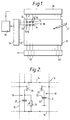
- Figure 1 is a schematic diagram of the display device;
- Figure 2 is a schematic circuit diagram of a part of a display panel of the display device showing typical picture and sensing elements of the panel;
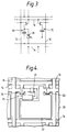
- Figure 3 is similar to Figure 2 but illustrates an alternative form of sensing element;
- Figure 4 is a diagrammatic plan view of a picture element and a sensing element of a panel of the display device;
- Figure 5 illustrates the waveforms and relative timing of signals present in operation of the display device; and
- Figure 6 shows a part of a detection circuit of the display device.
- It should be understood that the Figures are merely schematic and are not drawn to scale. In particular certain dimensions may have been exaggerated whilst other dimensions may have been reduced. It should also be understood that the same reference numerals are used through the Figure to indicate the same or similar parts.
- Referring to Figure 1, the display device is an active matrix addressed liquid crystal display device comprising a display panel, 10, having a row and column array of individually operable picture elements which consists of m rows (1 to m) with n horizontally arranged picture elements (1 to n) in each row. Each picture element, referenced at 12, is located at a respective intersection between crossing sets of m
row address conductors 14 and ncolumn address conductors 16. Only a few of the picture elements are shown in Figure 1, for clarity. In practice the total number of picture elements in the matrix array (m x n) may be several hundreds of thousands. The display device is suitable to provide a datagraphic display or a picture display. - The
display panel 10 further includes a matrix array ofsensing elements 18, there being one sensing element located adjacent eachpicture element 12, except for the first column of picture elements, giving a high resolution sensing capability. - The circuit of a typical combination of picture and sensing elements is shown in Figure 2. Each
picture element 12 comprises a switching device in the form of a thin film field effect transistor, TFT, 20 connected with a liquidcrystal display element 21, the impedance of the display element being represented by a capacitor. The gates of allTFTs 20 of the picture elements in one row are connected to a respective one of therow address conductors 14. The sources of allTFTs 20 of picture elements in one column are connected to a respective one of thecolumn address conductors 16. The drain terminals of theTFTs 20 are connected to afirst electrode 22 of their associateddisplay elements 21. As in standard practice in matrix liquid crystal display devices using TFT switches, the sets of row andcolumn address conductors TFTs 20, and the display elementfirst electrodes 22 are all carried on a transparent supporting plate of insulating material, for example glass. Thedisplay panel 10 comprises a second transparent supporting plate arranged parallel to, and spaced from, this supporting plate, which second plate carries a continuous transparent conductive layer constituting an electrode, 23, common to all display elements. Twisted nematic liquid crystal material is disposed between the two plates, the plates being sealed together around their periphery. Each liquid crystal display element thus consists of a first electrode, 22, connected to an associatedTFT 20, an opposing portion of thecommon electrode 23, and liquid crystal material therebetween. The opposing plates are provided internally with orientation layers and externally with polarising layers in the usual manner. - Each
sensing element 18 comprises a switching device in the form of aTFT 24. In similar manner to theTFTs 20 of the picture elements, the gates of allTFTs 24 of sensing elements in the same row are connected to a respective one of therow address conductors 14 and the sources of allTFTs 24 of sensing elements in the same column are connected to a respective one of thecolumn address conductors 16. The source of theTFT 24 of a sensing element is connected to one side ofcharge storage device 25 in the form of a capacitor. The other side of the capacitor is connected to an adjacentrow address conductor 14 associated with the next row of picture/sensing elements. In an alternative arrangement the capacitor of a sensing element may instead be connected to a dedicated auxiliary row conductor which extends in the row direction parallel to and between adjacentrow address conductor 14 and which is common to the capacitors of all sensing elements in a row. With this arrangement it is possible to control more easily the potential applied to this side of the capacitor, although it requires the provision of a set of such row conductors, corresponding in number to the number of rows of sensing elements, in addition to the row address conductors. In a further alternative arrangement, the source of theTFT 24 may be connected to the samecolumn address conductor 16 as theTFT 20 rather than an adjacent column conductor as shown. - The
sensing element 18 further includes aphotosensitive element 26 which is connected across thecapacitor 25 between the drain of theTFT 24 and the next row address conductor 14 (or supplementary row conductor if used). In this embodiment the The photosensitive element can comprise other forms of photo conductive device which exhibit an increase in conductance in response to being illuminated, for example, a photo-diode, comprising a pin, nip, Schottky, or the like photo-diode. All such photosensitive elements can be fabricated using thin film processes. Alternatively, each element 28 can comprise a TFT whose source is connected to the next row conductor or an auxiliary row conductor and whose gate is connected to its drain which in turn is connected to the node between theTFT 24 andcapacitor 25. - The
components TFTs 20, thefirst electrodes 22 of thedisplay elements 21, and the sets of row and column address conductors. - The arrays of picture and sensing elements and the sets of row and column address conductors are fabricated on the supporting plate using technology commonly employed in the manufacture of active matrix liquid crystal display devices. This technology, which typically involves the deposition and definition of superimposed thin film layers, is well established and widely documented and it is not thought necessary therefore to describe here in detail such fabrication techniques. Examples of suitable manufacturing processes are described in the aforementioned US-A-4,345,248, details of which are incorporated herein by reference.
- In this particular embodiment the
TFTs resistors 26 comprise amorphous silicon material. The display element electrodes comprise ITO, and the row and column conductors and the plates of thecapacitors 26 comprise metal, for example aluminium or chromium. Other materials can be used, as will be apparent to persons skilled in the art. - Referring again to Figure 1, the
row address conductors 14 are connected at their one ends to arow drive circuit 34 comprising a digital shift register whose operation is controlled by timing signals provided by a timing andcontrol circuit 35 and which sequentially addresses therow conductors 14 on a row at a time basis. Therow drive circuit 34 applies a selection, gating, signal to eachrow address conductor 14 in turn, and holds eachconductor 14 at a reference potential level in the interval between successive selection signals. Thecolumn address conductors 16 are connected at their one ends to acolumn drive circuit 36, comprising a sample and hold circuit operated by a shift register to perform serial to parallel conversion, to which data in serial form is supplied from the timing andcontrol circuit 35. A data signal for each picture element in a row is provided by thecircuit 36 to thecolumn address conductors 16, with data signals for the picture elements of each row in turn being supplied to theconductors 16 in synchronism with the selection signals applied to therow address conductors 14. Thecircuits circuit 36 is similarly of conventional form apart from a modification which will be described subsequently. Briefly, theTFTs 20 of the picture elements in a row are turned on by the application of a selection signal to their associated row address conductor whereupon the data signals present on thecolumn address conductors 16 are transferred to therespective display elements 21 of that row. Light transmission through the display elements is modulated in accordance with the level of the applied data signal. Following a row address, and termination of the selection signal, theTFTs 20 ar turned off thereby isolating the associateddisplay elements 21 from theconductors 16 so that the display elements remain substantially in the state into which they were driven until the next time they are addressed, i.e. in the subsequent field period. Each display element can produce a range of display effects, i.e. grey scale. In a variant, the data signals may be binary signals producing a two level display output, light and dark, from the display elements. In this case the column drive circuit can be of simplified form comprising a digital circuit, for example a shift register circuit with latched outputs. - In order to prevent degradation of the liquid crystal material, the polarity of the drive voltage applied to the display elements is periodically inverted, in accordance with known practice, for example after every field.
- Preferably, for reasons which will become apparent, part of the inverting column conductor data signals is applied to the
common electrode 23 of the display elements so that the range of data signal voltages present on thecolumn conductors 16 is minimised. - The other ends of the
column address conductors 16 are connected to adetection circuit 40 which comprises a set of sense amplifiers, one for each column conductor, whose function is to provide an output indicative of the state of thesensing elements 18, that is, according to whether or not they have been illuminated, for example by means of a light pen, referenced at 41 in Figure 1. The charge state ofcapacitor 25, e.g. the level of the charge stored in acapacitor 25, is dependent on whether or not the associatedphotosensitive element 26 has been illuminated. The detection circuit periodically addresses thecapacitors 25 to sense their charge state and provides an output in accordance therewith indicating whether or not the capacitors have been subjected to illumination in the interval between successive addressing. Thelight pen 41, which consists of a light source which continuously emits light in operation, can be moved over the display panel whereby sensing elements located under the path of travel of the light pen are illuminated. The detection of those sensing elements which have been illuminated in this manner, representing the pattern of the light pen movement, enables data or information to be written into the device. The light pen emits a narrow, intense beam of light of a wavelength to which thephotosensitive elements 26 of the sensing elements are responsive. If a high resolution input is required, the size of the beam should be sufficiently narrow to illuminate only one sensing element of the array at any given time. The beam should be large enough such that one sensing element is always illuminated. An ideal size would be a beam of diameter aprroximately equal to the diagonal of the picture/sensing element area. - In order to improve discrimination between signals from written and unwritten sensing elements the
photosensitive elements 26 can be formed so as to have a wavelength dependent photosensitivity which peaks in the region of the spectrum where the light pen output is concentrated. In this case, the light pen may comprise a narrow-band emitter, such as an LED. - Examples of the signal waveforms applied to row and column address conductors in operation are illustrated in Figure 5, in which VR and Vc are respectively the row and column voltage waveforms. The row selection signal comprises a pulse of duration Tr and magnitude Vg. For the remainder of the field period TF, where TF can be approximately equal to m.Tr, the row conductor is held at a constant reference level VO.
- The data signal intended for a picture element is indicated at Vd, having a range of possible values according to the display effect desired, and is applied by the
column driver circuit 36 to thecolumn conductor 16 for a part only, shown at T2, of the duration of the selection signal. The column drive circuit is modified so as to present a high impedance to the column conductor in the intervals between successive data signals being applied to the column conductor, and intended for respective picture elements in the column of picture elements associated with the column conductor, and during these intervals a constant predetermined potential, indicated at Vx, is applied to the column conductor by thedetection circuit 40. Thus during the first part, T1, of the row selection period Tr for arow address conductor 14, the column drive circuit is switched to a high impedance state and during the latter part, T2, of the row selection period the data signal Vd is applied to thecolumn conductor 16. As a result thedisplay element 21 of thepicture element 12 associated with these row and column conductors is charged to a voltage, VLC, given by:

where Ve is the voltage of theelectrode 23 common to all display elements. - The selection signal pulse Vg applied to a
row conductor 14 also turns on theTFTs 24 of the row ofsensing elements 18 associated with that row conductor. As a result, during the period T2 thecapacitors 25 of the row of sensing elements are charged to a voltage according to the voltage present on their respective column conductor with eachcapacitor 25 being charged to a level, Vs, given by:-

bearing in mind that the other side of the capacitor is connected to the succeeding row address address conductor which as this time is held at the reference level Vo. Since the column voltage Vd can vary, in dependence on display requirements, the voltage Vs can also vary. If the mean data signal voltage (Vd) is Vm and the range of possible data signal voltages is 2Vn then Vs can be in the range (Vm + Vn - Vo) to (Vm - Vn - Vo). - Following termination of the row selection signal (Vg) the
TFTs 24, like theTFTs 20, connected to therow conductor 14 are turned off, thereby isolating thecapacitors 25, until the row of sensing elements are next addressed in the subsequent field period. During the interval between successive addressing of the sensing elements in a row, corresponding to a field period, theircapacitors 25 can be discharged to a greater or lesser extent by photoconduction through their associated photosensitive elements. - At the start of the next row selection pulse signal applied to that
row conductor 14, i.e. at the start of period T1, when the column drivers are in the high impedance state, theTFTs column conductors 16 at this time is set by thedetection circuit 40 to Vx and the charging current required to charge thecapacitors 25 and thedisplay elements 21 to the column voltage Vx flows via thedetection circuit 40 where it is sensed. The sensitivity of thephotosensitive elements 26 of theelements 18 is chosen so that under normal, ambient, illumination thecapacitors 25 are not discharged to any significant extent and accordingly very little charging current flows during this period in the case where the photosensitive elements have been subjected only to ambient illumination in the preceding field period. There will normally be some charging current since acapacitor 25 may have been charged to any voltage in the possible range of data signal voltages Vd on the associatedcolumn conductor 16 during the latter part, T2, of the previous row address period and the voltage across thecapacitor 25 is now reset to Vx-Vo. The maximum charge flowing into acapacitor 25 will be in the range C(Vx-Vm-Vn) + dQ to C(Vx-Vm+Vn) + dQ, where dQ is the charge needed to replace the leakage caused by ambient illumination incident on thephotosensitive element 26 and C is the capacitance. - If during the preceding field period a
sensing element 18 has been "written" with thelight pen 41 then the comparatively high light intensity will have caused thephotosensitive element 26 of thesensing element 18 to conduct heavily, thus substantially discharging thecapacitor 25 so that a charge C(Vx-Vo) will flow into itscapacitor 25. - The sense amplifiers of the
detection circuit 40 connected torespective column conductors 16, which may be current or charge sensing amplifiers, are responsive to the charges supplied to thecapacitors 25 in the period T1. After amplification in the sense amplifiers the signals produced as a result of the recharging of thecapacitors 25 are passed to a respective threshold circuit of thedetection circuit 40 whose output switches state if the signal level exceeds a predetermined value which is set to lie between that produced by a "written" and an "unwritten" sensing element. - By selecting Vx so as to lie slightly below Vm-Vn the polarity of the charging signals for written and unwritten sensing elements will be opposite, which can make discrimination between them easier.
- The detection circuit will now be described with reference to Figure 6 although it should be appreciated that other forms of detection circuit could be employed for sensing the states of the sensing elements. Figure 6 illustrates schematically the circuit of one stage, 50, of the
detection circuit 40 associated with arespective column conductor 16, thecircuit 40 having identical stages for other column conductors. The stage consists of asense amplifier 52, which in this case is a charge sensitive amplifier. During the period T3 (Figure 5) of a row selection period beginning after the start of the data signal Vd and terminating slightly before the start of the row selection pulse signal Vg for the succeedingrow conductor 14, and after termination of Vd, afeedback capacitor 53 of theamplifier 52 is discharged, the amplifier output online 54 is reset to Vx and theinput 55 to the amplifier, connected to the associatedcolumn conductor 16, is clamped to the same potential (Vx) by the closure of theelectronic switch 56 connected across thecapacitor 53. At the end of the period T3 theswitch 56 is opened and during the period T1 of this next row address period, in which a subsequent row address conductor is supplied with a selection signal Vg, the signal from the column conductor representing the charge current for acapacitor 25 of the selected sensing element associated with the column conductor is integrated by thesense amplifier 52 and its associatedcapacitor 53. Near the end of this period T1 the resulting, integrated, output signal online 54 is transferred tocapacitor 58 by closing theelectronic switch 59 for a short period. Theswitch 59 is then opened before the beginning of period T2, isolating thecapacitor 58 from thesource amplifier 52, and therefore from the effects of the data signal, Vd, which is then applied to the column conductor. During this period, T2, the signals from the stages of thedetection circuit 40 associated with every column conductor can be read out sequentially viarespective buffers 61, by closing theswitches 60 for each stage in turn, so as to achieve parallel to serial conversion, with the serial output of thedetection circuit 40 being provided on theoutput line 62. The timing of the operation of theswitches circuit 35. - The serial output on
line 62 is fed to a discriminator, for example a threshold level detector, whose binary output has first and second levels, representing the two possible states of the sensing elements, e.g. written or unwritten. The output of thedetection circuit 40 may be supplied to one input of a data processing circuit, with an associated memory device, which provides signals to the column driver circuit for display purposes, in similar manner to that described in US-A-4345248. - This operation of the detection circuit is repeated for each row of sense elements, in synchronism with the addressing of the rows of picture elements, so that the states of the array of sensing elements are determined over the course of the display field, the array being repeatedly addressed in this manner in successive display fields.
- In another form of the detection circuit, each stage may include a respective threshold detector. Most conveniently, this can be achieved by including the thresholding function in the
amplifier circuit 61. Theswitch 60 can then be a digital switch and the output provided online 62 digital rather than analogue. Severalparallel output lines 62 may be provided, each of which is connected with certain stages only, for example every eighth stage, so that a parallel output is obtained. The serial data rate in eachoutput line 62 is then considerably reduced compared with that for a single output line. - Various modifications to the device are possible. For example, as mentioned previously, the
capacitors 25 andphotosensitive elements 26 of a row ofsensing element 18 may be connected at their sides remote from theTFTs 24 to a respective supplementary row conductor to which a reference potential Vo is continuously applied rather than to the nextrow address conductor 14. - It is envisaged that the
photosensitive element 26 andcapacitor 25 of each sensing element need not be provided as separately formed components as described previously but may instead be integrated in one component, for example as a photoconductive element having a self capacitance adequate to satisfy the operational requirements described above. - By sensing the ambient light level using a separate photosensor situated on the panel outside the display area or using a signal derived from the average of all sensing element outputs over the last field compensation may be achieved for the part of the output signal produced by the discharge of the
capacitors 25 caused by ambient illumination (i.e. dQ). - If a high resolution input capability is not required, then the numbers of sensing elements in the array can be reduced, for example with a sensing element being provided for every two, three or four picture elements.
Claims (9)
- An active matrix liquid crystal display device comprising a display panel having an array of picture elements each comprising a liquid crystal display element and an associated switching means, sets of row and column address conductors connected to the picture elements and drive means for applying drive signals to the sets of conductors for driving the picture elements, the display panel further including an array of active addressed sensing elements each comprising a photo-sensitive element and a switching device, characterised in that the sensing elements each include a charge storage means which is connected to the switching device, in that the switching devices are operable by the drive signals applied to the row and column address conductors so as to charge the charge storage means, in that the photo-sensitive element of each sensing element is arranged so as to discharge the charge storage means in response the illumination thereof, and in that the device includes detection means connected to the sensing elements for detecting periodically the state of charge of their charge storage means.
- An active matrix liquid crystal display device according to Claim 1, characterised in that the drive means is arranged to apply data signals to the column address conductors and a selection signal to each row address conductor in turn so as to operate the switching means of the picture elements associated with the row address conductor to apply the data signals to their respective display elements, and in that the switching devices of each row of sensing elements are operable by a selection signal applied to an associated row address conductor so as to charge the charge storage means of the sensing elements according to the data signals.
- An active matrix liquid crystal display device according to Claim 1 or Claim 2, characterised in that the charge storage means of each sensing element comprises a capacitor connected between the switching device of the sensing element and a row address conductor adjacent that associated with the switching means of the sensing element.
- An active matrix liquid crystal display device according to Claim 1 or Claim 2, characterised in that the charge storage means of each sensing element comprises a capacitor connected between the switching device of the sensing element and a source of predetermined potential comprising an auxiliary row conductor common to all sensing elements in a row.
- An active matrix liquid crystal display device according to any one of the preceding claims, characterised in that the detection means is arranged to determine the state of the sensing element charge storage means during a display field.
- An active matrix liquid crystal display device according to Claim 5, characterised in that the detection means is operable to determine the state of the charge storage means of a row of sensing elements associated with a row address conductor each time a drive signal is applied by the drive means to that row address conductor for driving the associated row of picture elements.
- An active matrix liquid crystal display device according to Claim 5 or Claim 6, characterised in that the drive means is arranged to apply a selection signal to each row address conductor and data signals to the column address conductors to drive the picture elements with each row address period, defined by the duration of the selection signal applied to a row address conductor, being divided into a detection interval during which the detection means is operable to detect the state of a sensing element associated with that row address conductor followed by a drive interval during which the drive means is operable to apply data signals for the row of picture elements to the column address conductors.
- An active matrix liquid crystal display device according to any one of Claims 5 to 7, characterised in that the detection means is arranged to detect the state of charge of the storage means of a sensing element by measuring the charging characteristic of the charge storage means in response to the application thereto of a predetermined potential.
- An active matrix liquid crystal display device according to any one of the preceding claims, characterised in that the device further comprises a light emitting means which is movable over the array of sensing elements so as to illuminate the photo-sensitive elements thereof, and in that the photo-sensitive elements are formed so as to have a wavelength dependent photosensitivity which peaks substantially in the region of the spectrum at which the output of the light emitting means is concentrated.
Applications Claiming Priority (2)
| Application Number | Priority Date | Filing Date | Title |
|---|---|---|---|
| GB909027481A GB9027481D0 (en) | 1990-12-19 | 1990-12-19 | Matrix display device with write-in facility |
| GB9027481 | 1990-12-19 |
Publications (3)
| Publication Number | Publication Date |
|---|---|
| EP0491436A2 true EP0491436A2 (en) | 1992-06-24 |
| EP0491436A3 EP0491436A3 (en) | 1993-02-10 |
| EP0491436B1 EP0491436B1 (en) | 1995-09-27 |
Family
ID=10687212
Family Applications (1)
| Application Number | Title | Priority Date | Filing Date |
|---|---|---|---|
| EP91203273A Expired - Lifetime EP0491436B1 (en) | 1990-12-19 | 1991-12-12 | Matrix display device with write-in facility |
Country Status (5)
| Country | Link |
|---|---|
| US (1) | US5485177A (en) |
| EP (1) | EP0491436B1 (en) |
| JP (1) | JP3188498B2 (en) |
| DE (1) | DE69113418T2 (en) |
| GB (1) | GB9027481D0 (en) |
Cited By (12)
| Publication number | Priority date | Publication date | Assignee | Title |
|---|---|---|---|---|
| EP0509589A2 (en) * | 1991-04-17 | 1992-10-21 | Philips Electronics Uk Limited | Optical touch input device |
| EP0587236A3 (en) * | 1992-09-07 | 1994-09-14 | Philips Electronics Uk Ltd | Matrix display device with light sensing function |
| EP0708400A3 (en) * | 1994-10-18 | 1998-01-14 | Xerox Corporation | Combination of 2-D detector array with display for image processing |
| EP0915367A1 (en) * | 1997-04-22 | 1999-05-12 | Matsushita Electric Industrial Co., Ltd. | Liquid crystal display with image reading function, image reading method and manufacturing method |
| US5959617A (en) * | 1995-08-10 | 1999-09-28 | U.S. Philips Corporation | Light pen input systems |
| WO2001099191A1 (en) * | 2000-06-20 | 2001-12-27 | Koninklijke Philips Electronics N.V. | Light-emitting matrix array display devices with light sensing elements |
| KR20030013135A (en) * | 2001-08-07 | 2003-02-14 | 권무순 | Dizitizer using Photoelectric Transformation Element |
| KR100717200B1 (en) * | 2000-06-20 | 2007-05-11 | 코닌클리케 필립스 일렉트로닉스 엔.브이. | Matrix array display devices with light sensing elements |
| EP2085810A1 (en) * | 2006-10-19 | 2009-08-05 | Sharp Kabushiki Kaisha | Display apparatus |
| DE102009025483A1 (en) * | 2009-06-18 | 2011-01-05 | Siemens Aktiengesellschaft | display |
| TWI401641B (en) * | 2004-12-23 | 2013-07-11 | Samsung Display Co Ltd | Display device, driving method thereof, and driving apparatus for the display device |
| US9971456B2 (en) | 2002-02-20 | 2018-05-15 | Apple Inc. | Light sensitive display with switchable detection modes for detecting a fingerprint |
Families Citing this family (41)
| Publication number | Priority date | Publication date | Assignee | Title |
|---|---|---|---|---|
| JP2653014B2 (en) * | 1993-07-26 | 1997-09-10 | 日本電気株式会社 | Active matrix liquid crystal display device |
| WO1997035297A2 (en) * | 1996-03-18 | 1997-09-25 | Philips Electronics N.V. | Display device |
| GB0014074D0 (en) * | 2000-06-10 | 2000-08-02 | Koninkl Philips Electronics Nv | Active matrix array devices |
| US6747290B2 (en) * | 2000-12-12 | 2004-06-08 | Semiconductor Energy Laboratory Co., Ltd. | Information device |
| JP3959454B2 (en) * | 2001-10-22 | 2007-08-15 | シャープ株式会社 | Input device and input / output device |
| GB2381644A (en) * | 2001-10-31 | 2003-05-07 | Cambridge Display Tech Ltd | Display drivers |
| US7009663B2 (en) * | 2003-12-17 | 2006-03-07 | Planar Systems, Inc. | Integrated optical light sensitive active matrix liquid crystal display |
| US7053967B2 (en) * | 2002-05-23 | 2006-05-30 | Planar Systems, Inc. | Light sensitive display |
| US7023503B2 (en) * | 2002-02-20 | 2006-04-04 | Planar Systems, Inc. | Image sensor with photosensitive thin film transistors |
| AU2003216481A1 (en) * | 2002-03-01 | 2003-09-16 | Planar Systems, Inc. | Reflection resistant touch screens |
| US7219241B2 (en) * | 2002-11-30 | 2007-05-15 | Intel Corporation | Method for managing virtual and actual performance states of logical processors in a multithreaded processor using system management mode |
| US20080084374A1 (en) * | 2003-02-20 | 2008-04-10 | Planar Systems, Inc. | Light sensitive display |
| US20080048995A1 (en) * | 2003-02-20 | 2008-02-28 | Planar Systems, Inc. | Light sensitive display |
| TWI363206B (en) * | 2003-02-28 | 2012-05-01 | Samsung Electronics Co Ltd | Liquid crystal display device |
| KR100954082B1 (en) * | 2003-04-08 | 2010-04-23 | 삼성전자주식회사 | Liquid crystal display device |
| GB0319909D0 (en) * | 2003-08-23 | 2003-09-24 | Koninkl Philips Electronics Nv | Touch-input active matrix display device |
| US20050134749A1 (en) * | 2003-12-19 | 2005-06-23 | Adiel Abileah | Reflection resistant display |
| US20060007248A1 (en) * | 2004-06-29 | 2006-01-12 | Damoder Reddy | Feedback control system and method for operating a high-performance stabilized active-matrix emissive display |
| US7773139B2 (en) * | 2004-04-16 | 2010-08-10 | Apple Inc. | Image sensor with photosensitive thin film transistors |
| JP2006323261A (en) * | 2005-05-20 | 2006-11-30 | Mitsubishi Electric Corp | Method for driving display device |
| US20070109239A1 (en) * | 2005-11-14 | 2007-05-17 | Den Boer Willem | Integrated light sensitive liquid crystal display |
| JP2007241358A (en) * | 2006-03-06 | 2007-09-20 | Hitachi Displays Ltd | Image display |
| KR100989959B1 (en) * | 2008-10-27 | 2010-10-26 | 하이디스 테크놀로지 주식회사 | In-Cell Type Optical Touch Sensing Liquid Crystal Display and Method for Detecting Light Performed by the LCD |
| JP5489114B2 (en) * | 2009-11-12 | 2014-05-14 | 株式会社ジャパンディスプレイ | Display device with imaging function, driving method, and electronic apparatus |
| US9823785B2 (en) | 2010-09-09 | 2017-11-21 | 3M Innovative Properties Company | Touch sensitive device with stylus support |
| US10019119B2 (en) | 2010-09-09 | 2018-07-10 | 3M Innovative Properties Company | Touch sensitive device with stylus support |
| US9389724B2 (en) | 2010-09-09 | 2016-07-12 | 3M Innovative Properties Company | Touch sensitive device with stylus support |
| US9310923B2 (en) | 2010-12-03 | 2016-04-12 | Apple Inc. | Input device for touch sensitive devices |
| US9329703B2 (en) | 2011-06-22 | 2016-05-03 | Apple Inc. | Intelligent stylus |
| US8638320B2 (en) | 2011-06-22 | 2014-01-28 | Apple Inc. | Stylus orientation detection |
| US8928635B2 (en) | 2011-06-22 | 2015-01-06 | Apple Inc. | Active stylus |
| US9176604B2 (en) | 2012-07-27 | 2015-11-03 | Apple Inc. | Stylus device |
| US9652090B2 (en) | 2012-07-27 | 2017-05-16 | Apple Inc. | Device for digital communication through capacitive coupling |
| US9557845B2 (en) | 2012-07-27 | 2017-01-31 | Apple Inc. | Input device for and method of communication with capacitive devices through frequency variation |
| US10048775B2 (en) | 2013-03-14 | 2018-08-14 | Apple Inc. | Stylus detection and demodulation |
| US10067580B2 (en) | 2013-07-31 | 2018-09-04 | Apple Inc. | Active stylus for use with touch controller architecture |
| US9576542B1 (en) * | 2014-12-02 | 2017-02-21 | Amazon Technologies, Inc. | Using display components for light sensing |
| US10067618B2 (en) | 2014-12-04 | 2018-09-04 | Apple Inc. | Coarse scan and targeted active mode scan for touch |
| CN104679355B (en) * | 2015-03-19 | 2017-10-10 | 合肥鑫晟光电科技有限公司 | A kind of optical touch screen and display device |
| US10474277B2 (en) | 2016-05-31 | 2019-11-12 | Apple Inc. | Position-based stylus communication |
| EP3850323A4 (en) * | 2018-09-12 | 2022-06-08 | Lenexa Medical Pty Ltd | Addressing circuit for conductor arrays |
Citations (2)
| Publication number | Priority date | Publication date | Assignee | Title |
|---|---|---|---|---|
| US4345248A (en) * | 1979-12-14 | 1982-08-17 | Citizen Watch Company Limited | Liquid crystal display device with write-in capability |
| US4655552A (en) * | 1984-03-17 | 1987-04-07 | Citizen Watch Co., Ltd. | Flat panel display device having on-screen data input function |
Family Cites Families (5)
| Publication number | Priority date | Publication date | Assignee | Title |
|---|---|---|---|---|
| JPS56104387A (en) * | 1980-01-22 | 1981-08-20 | Citizen Watch Co Ltd | Display unit |
| GB2081018B (en) * | 1980-07-31 | 1985-06-26 | Suwa Seikosha Kk | Active matrix assembly for display device |
| DE3602796A1 (en) * | 1986-01-30 | 1987-08-06 | Messerschmitt Boelkow Blohm | SENSOR ELEMENT WITH A MEMORY FOR ABNORMAL CHANGES IN THE INCIDENT LIGHT INTENSITY |
| JPH02278326A (en) * | 1989-04-19 | 1990-11-14 | Sharp Corp | Information input/output device |
| US5204661A (en) * | 1990-12-13 | 1993-04-20 | Xerox Corporation | Input/output pixel circuit and array of such circuits |
-
1990
- 1990-12-19 GB GB909027481A patent/GB9027481D0/en active Pending
-
1991
- 1991-11-26 US US07/797,852 patent/US5485177A/en not_active Expired - Fee Related
- 1991-12-12 EP EP91203273A patent/EP0491436B1/en not_active Expired - Lifetime
- 1991-12-12 DE DE69113418T patent/DE69113418T2/en not_active Expired - Fee Related
- 1991-12-19 JP JP33705991A patent/JP3188498B2/en not_active Expired - Fee Related
Patent Citations (2)
| Publication number | Priority date | Publication date | Assignee | Title |
|---|---|---|---|---|
| US4345248A (en) * | 1979-12-14 | 1982-08-17 | Citizen Watch Company Limited | Liquid crystal display device with write-in capability |
| US4655552A (en) * | 1984-03-17 | 1987-04-07 | Citizen Watch Co., Ltd. | Flat panel display device having on-screen data input function |
Cited By (19)
| Publication number | Priority date | Publication date | Assignee | Title |
|---|---|---|---|---|
| EP0509589B1 (en) * | 1991-04-17 | 1997-01-29 | Philips Electronics Uk Limited | Optical touch input device |
| US5838308A (en) * | 1991-04-17 | 1998-11-17 | U.S. Philips Corporation | Optical touch input device |
| EP0509589A2 (en) * | 1991-04-17 | 1992-10-21 | Philips Electronics Uk Limited | Optical touch input device |
| EP0587236A3 (en) * | 1992-09-07 | 1994-09-14 | Philips Electronics Uk Ltd | Matrix display device with light sensing function |
| US5386543A (en) * | 1992-09-07 | 1995-01-31 | U.S. Philips Corporation | Matrix display device with light sensing function and time-shared amplifier |
| US5917464A (en) * | 1994-10-18 | 1999-06-29 | Xerox Corporation | Combination of 2-D detector array with display for image processing |
| EP0708400A3 (en) * | 1994-10-18 | 1998-01-14 | Xerox Corporation | Combination of 2-D detector array with display for image processing |
| US5959617A (en) * | 1995-08-10 | 1999-09-28 | U.S. Philips Corporation | Light pen input systems |
| EP0915367A1 (en) * | 1997-04-22 | 1999-05-12 | Matsushita Electric Industrial Co., Ltd. | Liquid crystal display with image reading function, image reading method and manufacturing method |
| EP0915367A4 (en) * | 1997-04-22 | 2000-04-12 | Matsushita Electric Ind Co Ltd | Liquid crystal display with image reading function, image reading method and manufacturing method |
| WO2001099191A1 (en) * | 2000-06-20 | 2001-12-27 | Koninklijke Philips Electronics N.V. | Light-emitting matrix array display devices with light sensing elements |
| KR100716557B1 (en) * | 2000-06-20 | 2007-05-10 | 코닌클리케 필립스 일렉트로닉스 엔.브이. | Light-emitting matrix array display devices with light sensing elements |
| KR100717200B1 (en) * | 2000-06-20 | 2007-05-11 | 코닌클리케 필립스 일렉트로닉스 엔.브이. | Matrix array display devices with light sensing elements |
| KR20030013135A (en) * | 2001-08-07 | 2003-02-14 | 권무순 | Dizitizer using Photoelectric Transformation Element |
| US9971456B2 (en) | 2002-02-20 | 2018-05-15 | Apple Inc. | Light sensitive display with switchable detection modes for detecting a fingerprint |
| TWI401641B (en) * | 2004-12-23 | 2013-07-11 | Samsung Display Co Ltd | Display device, driving method thereof, and driving apparatus for the display device |
| EP2085810A1 (en) * | 2006-10-19 | 2009-08-05 | Sharp Kabushiki Kaisha | Display apparatus |
| EP2085810A4 (en) * | 2006-10-19 | 2011-01-19 | Sharp Kk | Display apparatus |
| DE102009025483A1 (en) * | 2009-06-18 | 2011-01-05 | Siemens Aktiengesellschaft | display |
Also Published As
| Publication number | Publication date |
|---|---|
| GB9027481D0 (en) | 1991-02-06 |
| EP0491436A3 (en) | 1993-02-10 |
| JPH04343387A (en) | 1992-11-30 |
| US5485177A (en) | 1996-01-16 |
| DE69113418D1 (en) | 1995-11-02 |
| DE69113418T2 (en) | 1996-05-15 |
| EP0491436B1 (en) | 1995-09-27 |
| JP3188498B2 (en) | 2001-07-16 |
Similar Documents
| Publication | Publication Date | Title |
|---|---|---|
| EP0491436B1 (en) | Matrix display device with write-in facility | |
| US5838308A (en) | Optical touch input device | |
| EP0587236B1 (en) | Matrix display device with light sensing function | |
| US10133384B2 (en) | Display device and method of driving the same | |
| US8643594B2 (en) | Display device | |
| US7800602B2 (en) | Photosensitive display panel | |
| US7196307B2 (en) | Optical sensor, method of reading optical sensor, matrix-type optical sensor circuit, and electronic apparatus | |
| US5204661A (en) | Input/output pixel circuit and array of such circuits | |
| KR101462149B1 (en) | Touch sensor, liquid crystal display panel having the same and method of sensing the same | |
| KR100470881B1 (en) | Electric circuit | |
| US5237314A (en) | Addressing a matrix device using electro-optical switching | |
| US20060012575A1 (en) | Touch sensitive active matrix display and method for touch sensing | |
| GB2232251A (en) | Touch sensor array systems | |
| EP0731440B1 (en) | Data line drivers with common reference ramp for a display device | |
| GB2245708A (en) | Touch sensor array systems | |
| CA2169795A1 (en) | Data line drivers with column initialization transistor | |
| JP2002023658A (en) | Dimming system | |
| RU2449345C1 (en) | Display device | |
| CN101859784B (en) | Photosensitive element, driving method thereof and liquid crystal display using photosensitive element | |
| JPS6244796A (en) | Camera display unit | |
| WO2008018016A1 (en) | Electrophoretic display devices | |
| EP0731439B1 (en) | A data line driver for applying brightness signals to a display | |
| EP0807302A1 (en) | Multiplexer circuit | |
| KR101502371B1 (en) | Liquid Crystal Display Device and Method for Driving the Same | |
| US8717308B2 (en) | Display device with series connected optical sensors for determining touch position |
Legal Events
| Date | Code | Title | Description |
|---|---|---|---|
| PUAI | Public reference made under article 153(3) epc to a published international application that has entered the european phase |
Free format text: ORIGINAL CODE: 0009012 |
|
| AK | Designated contracting states |
Kind code of ref document: A2 Designated state(s): DE FR GB |
|
| PUAL | Search report despatched |
Free format text: ORIGINAL CODE: 0009013 |
|
| AK | Designated contracting states |
Kind code of ref document: A3 Designated state(s): DE FR GB |
|
| 17P | Request for examination filed |
Effective date: 19930719 |
|
| 17Q | First examination report despatched |
Effective date: 19931229 |
|
| GRAA | (expected) grant |
Free format text: ORIGINAL CODE: 0009210 |
|
| AK | Designated contracting states |
Kind code of ref document: B1 Designated state(s): DE FR GB |
|
| REF | Corresponds to: |
Ref document number: 69113418 Country of ref document: DE Date of ref document: 19951102 |
|
| ET | Fr: translation filed | ||
| PLBE | No opposition filed within time limit |
Free format text: ORIGINAL CODE: 0009261 |
|
| STAA | Information on the status of an ep patent application or granted ep patent |
Free format text: STATUS: NO OPPOSITION FILED WITHIN TIME LIMIT |
|
| 26N | No opposition filed | ||
| REG | Reference to a national code |
Ref country code: FR Ref legal event code: CD |
|
| REG | Reference to a national code |
Ref country code: GB Ref legal event code: IF02 |
|
| PGFP | Annual fee paid to national office [announced via postgrant information from national office to epo] |
Ref country code: DE Payment date: 20060214 Year of fee payment: 15 |
|
| PGFP | Annual fee paid to national office [announced via postgrant information from national office to epo] |
Ref country code: GB Payment date: 20061218 Year of fee payment: 16 |
|
| PG25 | Lapsed in a contracting state [announced via postgrant information from national office to epo] |
Ref country code: DE Free format text: LAPSE BECAUSE OF NON-PAYMENT OF DUE FEES Effective date: 20070703 |
|
| PGFP | Annual fee paid to national office [announced via postgrant information from national office to epo] |
Ref country code: FR Payment date: 20061227 Year of fee payment: 16 |
|
| GBPC | Gb: european patent ceased through non-payment of renewal fee |
Effective date: 20071212 |
|
| REG | Reference to a national code |
Ref country code: FR Ref legal event code: ST Effective date: 20081020 |
|
| PG25 | Lapsed in a contracting state [announced via postgrant information from national office to epo] |
Ref country code: GB Free format text: LAPSE BECAUSE OF NON-PAYMENT OF DUE FEES Effective date: 20071212 |
|
| PG25 | Lapsed in a contracting state [announced via postgrant information from national office to epo] |
Ref country code: FR Free format text: LAPSE BECAUSE OF NON-PAYMENT OF DUE FEES Effective date: 20071231 |