EP0490361B1 - Extrudeuse pour extrudat difficilement miscible - Google Patents
Extrudeuse pour extrudat difficilement miscible Download PDFInfo
- Publication number
- EP0490361B1 EP0490361B1 EP91121254A EP91121254A EP0490361B1 EP 0490361 B1 EP0490361 B1 EP 0490361B1 EP 91121254 A EP91121254 A EP 91121254A EP 91121254 A EP91121254 A EP 91121254A EP 0490361 B1 EP0490361 B1 EP 0490361B1
- Authority
- EP
- European Patent Office
- Prior art keywords
- extruder
- housing
- screw
- section
- recited
- Prior art date
- Legal status (The legal status is an assumption and is not a legal conclusion. Google has not performed a legal analysis and makes no representation as to the accuracy of the status listed.)
- Expired - Lifetime
Links
- 238000002156 mixing Methods 0.000 claims abstract description 38
- 230000010006 flight Effects 0.000 claims abstract description 14
- 239000000463 material Substances 0.000 claims abstract description 7
- 238000012545 processing Methods 0.000 claims description 13
- 229920001971 elastomer Polymers 0.000 claims description 11
- 239000005060 rubber Substances 0.000 claims description 11
- 230000007423 decrease Effects 0.000 claims description 7
- 238000011144 upstream manufacturing Methods 0.000 claims description 5
- 238000001125 extrusion Methods 0.000 claims description 3
- 238000001816 cooling Methods 0.000 claims description 2
- 238000010438 heat treatment Methods 0.000 claims 1
- 229920001169 thermoplastic Polymers 0.000 claims 1
- 239000004416 thermosoftening plastic Substances 0.000 claims 1
- 238000012546 transfer Methods 0.000 abstract description 55
- 238000000034 method Methods 0.000 description 13
- 230000008569 process Effects 0.000 description 12
- 238000004519 manufacturing process Methods 0.000 description 7
- 239000000203 mixture Substances 0.000 description 7
- 238000013461 design Methods 0.000 description 6
- 150000001875 compounds Chemical class 0.000 description 5
- 238000012360 testing method Methods 0.000 description 5
- 244000043261 Hevea brasiliensis Species 0.000 description 4
- 230000000694 effects Effects 0.000 description 4
- 229920003052 natural elastomer Polymers 0.000 description 4
- 229920001194 natural rubber Polymers 0.000 description 4
- 238000004140 cleaning Methods 0.000 description 3
- 238000000265 homogenisation Methods 0.000 description 3
- 230000010349 pulsation Effects 0.000 description 3
- 230000009467 reduction Effects 0.000 description 3
- 230000003247 decreasing effect Effects 0.000 description 2
- 238000011161 development Methods 0.000 description 2
- 230000018109 developmental process Effects 0.000 description 2
- 238000005516 engineering process Methods 0.000 description 2
- 230000006872 improvement Effects 0.000 description 2
- 239000000155 melt Substances 0.000 description 2
- 239000002184 metal Substances 0.000 description 2
- 208000035859 Drug effect increased Diseases 0.000 description 1
- 230000001070 adhesive effect Effects 0.000 description 1
- 229920005601 base polymer Polymers 0.000 description 1
- 230000005540 biological transmission Effects 0.000 description 1
- 230000008859 change Effects 0.000 description 1
- 238000010276 construction Methods 0.000 description 1
- 238000007872 degassing Methods 0.000 description 1
- 230000006866 deterioration Effects 0.000 description 1
- 238000005265 energy consumption Methods 0.000 description 1
- 239000000945 filler Substances 0.000 description 1
- 230000012447 hatching Effects 0.000 description 1
- 238000011835 investigation Methods 0.000 description 1
- 238000004898 kneading Methods 0.000 description 1
- 230000035515 penetration Effects 0.000 description 1
- 239000002861 polymer material Substances 0.000 description 1
- 230000008092 positive effect Effects 0.000 description 1
- 238000010008 shearing Methods 0.000 description 1
- 239000007787 solid Substances 0.000 description 1
- 229920003051 synthetic elastomer Polymers 0.000 description 1
- 239000005061 synthetic rubber Substances 0.000 description 1
- 239000012815 thermoplastic material Substances 0.000 description 1
Images


Classifications
-
- B—PERFORMING OPERATIONS; TRANSPORTING
- B29—WORKING OF PLASTICS; WORKING OF SUBSTANCES IN A PLASTIC STATE IN GENERAL
- B29C—SHAPING OR JOINING OF PLASTICS; SHAPING OF MATERIAL IN A PLASTIC STATE, NOT OTHERWISE PROVIDED FOR; AFTER-TREATMENT OF THE SHAPED PRODUCTS, e.g. REPAIRING
- B29C48/00—Extrusion moulding, i.e. expressing the moulding material through a die or nozzle which imparts the desired form; Apparatus therefor
- B29C48/25—Component parts, details or accessories; Auxiliary operations
- B29C48/36—Means for plasticising or homogenising the moulding material or forcing it through the nozzle or die
- B29C48/50—Details of extruders
- B29C48/68—Barrels or cylinders
- B29C48/685—Barrels or cylinders characterised by their inner surfaces, e.g. having grooves, projections or threads
- B29C48/687—Barrels or cylinders characterised by their inner surfaces, e.g. having grooves, projections or threads having projections with a short length in the barrel direction, e.g. pins
-
- B—PERFORMING OPERATIONS; TRANSPORTING
- B29—WORKING OF PLASTICS; WORKING OF SUBSTANCES IN A PLASTIC STATE IN GENERAL
- B29C—SHAPING OR JOINING OF PLASTICS; SHAPING OF MATERIAL IN A PLASTIC STATE, NOT OTHERWISE PROVIDED FOR; AFTER-TREATMENT OF THE SHAPED PRODUCTS, e.g. REPAIRING
- B29C48/00—Extrusion moulding, i.e. expressing the moulding material through a die or nozzle which imparts the desired form; Apparatus therefor
- B29C48/25—Component parts, details or accessories; Auxiliary operations
- B29C48/285—Feeding the extrusion material to the extruder
- B29C48/29—Feeding the extrusion material to the extruder in liquid form
-
- B—PERFORMING OPERATIONS; TRANSPORTING
- B29—WORKING OF PLASTICS; WORKING OF SUBSTANCES IN A PLASTIC STATE IN GENERAL
- B29C—SHAPING OR JOINING OF PLASTICS; SHAPING OF MATERIAL IN A PLASTIC STATE, NOT OTHERWISE PROVIDED FOR; AFTER-TREATMENT OF THE SHAPED PRODUCTS, e.g. REPAIRING
- B29C48/00—Extrusion moulding, i.e. expressing the moulding material through a die or nozzle which imparts the desired form; Apparatus therefor
- B29C48/25—Component parts, details or accessories; Auxiliary operations
- B29C48/36—Means for plasticising or homogenising the moulding material or forcing it through the nozzle or die
- B29C48/395—Means for plasticising or homogenising the moulding material or forcing it through the nozzle or die using screws surrounded by a cooperating barrel, e.g. single screw extruders
-
- B—PERFORMING OPERATIONS; TRANSPORTING
- B29—WORKING OF PLASTICS; WORKING OF SUBSTANCES IN A PLASTIC STATE IN GENERAL
- B29C—SHAPING OR JOINING OF PLASTICS; SHAPING OF MATERIAL IN A PLASTIC STATE, NOT OTHERWISE PROVIDED FOR; AFTER-TREATMENT OF THE SHAPED PRODUCTS, e.g. REPAIRING
- B29C48/00—Extrusion moulding, i.e. expressing the moulding material through a die or nozzle which imparts the desired form; Apparatus therefor
- B29C48/25—Component parts, details or accessories; Auxiliary operations
- B29C48/36—Means for plasticising or homogenising the moulding material or forcing it through the nozzle or die
- B29C48/50—Details of extruders
- B29C48/505—Screws
- B29C48/56—Screws having grooves or cavities other than the thread or the channel
-
- B—PERFORMING OPERATIONS; TRANSPORTING
- B29—WORKING OF PLASTICS; WORKING OF SUBSTANCES IN A PLASTIC STATE IN GENERAL
- B29C—SHAPING OR JOINING OF PLASTICS; SHAPING OF MATERIAL IN A PLASTIC STATE, NOT OTHERWISE PROVIDED FOR; AFTER-TREATMENT OF THE SHAPED PRODUCTS, e.g. REPAIRING
- B29C48/00—Extrusion moulding, i.e. expressing the moulding material through a die or nozzle which imparts the desired form; Apparatus therefor
- B29C48/25—Component parts, details or accessories; Auxiliary operations
- B29C48/36—Means for plasticising or homogenising the moulding material or forcing it through the nozzle or die
- B29C48/50—Details of extruders
- B29C48/505—Screws
- B29C48/63—Screws having sections without mixing elements or threads, i.e. having cylinder shaped sections
-
- B—PERFORMING OPERATIONS; TRANSPORTING
- B29—WORKING OF PLASTICS; WORKING OF SUBSTANCES IN A PLASTIC STATE IN GENERAL
- B29C—SHAPING OR JOINING OF PLASTICS; SHAPING OF MATERIAL IN A PLASTIC STATE, NOT OTHERWISE PROVIDED FOR; AFTER-TREATMENT OF THE SHAPED PRODUCTS, e.g. REPAIRING
- B29C48/00—Extrusion moulding, i.e. expressing the moulding material through a die or nozzle which imparts the desired form; Apparatus therefor
- B29C48/25—Component parts, details or accessories; Auxiliary operations
- B29C48/36—Means for plasticising or homogenising the moulding material or forcing it through the nozzle or die
- B29C48/50—Details of extruders
- B29C48/68—Barrels or cylinders
- B29C48/685—Barrels or cylinders characterised by their inner surfaces, e.g. having grooves, projections or threads
- B29C48/686—Barrels or cylinders characterised by their inner surfaces, e.g. having grooves, projections or threads having grooves or cavities
-
- B—PERFORMING OPERATIONS; TRANSPORTING
- B29—WORKING OF PLASTICS; WORKING OF SUBSTANCES IN A PLASTIC STATE IN GENERAL
- B29C—SHAPING OR JOINING OF PLASTICS; SHAPING OF MATERIAL IN A PLASTIC STATE, NOT OTHERWISE PROVIDED FOR; AFTER-TREATMENT OF THE SHAPED PRODUCTS, e.g. REPAIRING
- B29C48/00—Extrusion moulding, i.e. expressing the moulding material through a die or nozzle which imparts the desired form; Apparatus therefor
- B29C48/25—Component parts, details or accessories; Auxiliary operations
- B29C48/92—Measuring, controlling or regulating
-
- B—PERFORMING OPERATIONS; TRANSPORTING
- B29—WORKING OF PLASTICS; WORKING OF SUBSTANCES IN A PLASTIC STATE IN GENERAL
- B29C—SHAPING OR JOINING OF PLASTICS; SHAPING OF MATERIAL IN A PLASTIC STATE, NOT OTHERWISE PROVIDED FOR; AFTER-TREATMENT OF THE SHAPED PRODUCTS, e.g. REPAIRING
- B29C2948/00—Indexing scheme relating to extrusion moulding
- B29C2948/92—Measuring, controlling or regulating
- B29C2948/92009—Measured parameter
- B29C2948/92047—Energy, power, electric current or voltage
-
- B—PERFORMING OPERATIONS; TRANSPORTING
- B29—WORKING OF PLASTICS; WORKING OF SUBSTANCES IN A PLASTIC STATE IN GENERAL
- B29C—SHAPING OR JOINING OF PLASTICS; SHAPING OF MATERIAL IN A PLASTIC STATE, NOT OTHERWISE PROVIDED FOR; AFTER-TREATMENT OF THE SHAPED PRODUCTS, e.g. REPAIRING
- B29C2948/00—Indexing scheme relating to extrusion moulding
- B29C2948/92—Measuring, controlling or regulating
- B29C2948/92009—Measured parameter
- B29C2948/92085—Velocity
- B29C2948/92095—Angular velocity
-
- B—PERFORMING OPERATIONS; TRANSPORTING
- B29—WORKING OF PLASTICS; WORKING OF SUBSTANCES IN A PLASTIC STATE IN GENERAL
- B29C—SHAPING OR JOINING OF PLASTICS; SHAPING OF MATERIAL IN A PLASTIC STATE, NOT OTHERWISE PROVIDED FOR; AFTER-TREATMENT OF THE SHAPED PRODUCTS, e.g. REPAIRING
- B29C2948/00—Indexing scheme relating to extrusion moulding
- B29C2948/92—Measuring, controlling or regulating
- B29C2948/92009—Measured parameter
- B29C2948/92085—Velocity
- B29C2948/92104—Flow or feed rate
-
- B—PERFORMING OPERATIONS; TRANSPORTING
- B29—WORKING OF PLASTICS; WORKING OF SUBSTANCES IN A PLASTIC STATE IN GENERAL
- B29C—SHAPING OR JOINING OF PLASTICS; SHAPING OF MATERIAL IN A PLASTIC STATE, NOT OTHERWISE PROVIDED FOR; AFTER-TREATMENT OF THE SHAPED PRODUCTS, e.g. REPAIRING
- B29C2948/00—Indexing scheme relating to extrusion moulding
- B29C2948/92—Measuring, controlling or regulating
- B29C2948/92009—Measured parameter
- B29C2948/92209—Temperature
-
- B—PERFORMING OPERATIONS; TRANSPORTING
- B29—WORKING OF PLASTICS; WORKING OF SUBSTANCES IN A PLASTIC STATE IN GENERAL
- B29C—SHAPING OR JOINING OF PLASTICS; SHAPING OF MATERIAL IN A PLASTIC STATE, NOT OTHERWISE PROVIDED FOR; AFTER-TREATMENT OF THE SHAPED PRODUCTS, e.g. REPAIRING
- B29C2948/00—Indexing scheme relating to extrusion moulding
- B29C2948/92—Measuring, controlling or regulating
- B29C2948/92009—Measured parameter
- B29C2948/92314—Particular value claimed
-
- B—PERFORMING OPERATIONS; TRANSPORTING
- B29—WORKING OF PLASTICS; WORKING OF SUBSTANCES IN A PLASTIC STATE IN GENERAL
- B29C—SHAPING OR JOINING OF PLASTICS; SHAPING OF MATERIAL IN A PLASTIC STATE, NOT OTHERWISE PROVIDED FOR; AFTER-TREATMENT OF THE SHAPED PRODUCTS, e.g. REPAIRING
- B29C2948/00—Indexing scheme relating to extrusion moulding
- B29C2948/92—Measuring, controlling or regulating
- B29C2948/92323—Location or phase of measurement
- B29C2948/92485—Start-up, shut-down or parameter setting phase; Emergency shut-down; Material change; Test or laboratory equipment or studies
-
- B—PERFORMING OPERATIONS; TRANSPORTING
- B29—WORKING OF PLASTICS; WORKING OF SUBSTANCES IN A PLASTIC STATE IN GENERAL
- B29C—SHAPING OR JOINING OF PLASTICS; SHAPING OF MATERIAL IN A PLASTIC STATE, NOT OTHERWISE PROVIDED FOR; AFTER-TREATMENT OF THE SHAPED PRODUCTS, e.g. REPAIRING
- B29C2948/00—Indexing scheme relating to extrusion moulding
- B29C2948/92—Measuring, controlling or regulating
- B29C2948/92504—Controlled parameter
- B29C2948/92514—Pressure
-
- B—PERFORMING OPERATIONS; TRANSPORTING
- B29—WORKING OF PLASTICS; WORKING OF SUBSTANCES IN A PLASTIC STATE IN GENERAL
- B29C—SHAPING OR JOINING OF PLASTICS; SHAPING OF MATERIAL IN A PLASTIC STATE, NOT OTHERWISE PROVIDED FOR; AFTER-TREATMENT OF THE SHAPED PRODUCTS, e.g. REPAIRING
- B29C2948/00—Indexing scheme relating to extrusion moulding
- B29C2948/92—Measuring, controlling or regulating
- B29C2948/92504—Controlled parameter
- B29C2948/92542—Energy, power, electric current or voltage
-
- B—PERFORMING OPERATIONS; TRANSPORTING
- B29—WORKING OF PLASTICS; WORKING OF SUBSTANCES IN A PLASTIC STATE IN GENERAL
- B29C—SHAPING OR JOINING OF PLASTICS; SHAPING OF MATERIAL IN A PLASTIC STATE, NOT OTHERWISE PROVIDED FOR; AFTER-TREATMENT OF THE SHAPED PRODUCTS, e.g. REPAIRING
- B29C2948/00—Indexing scheme relating to extrusion moulding
- B29C2948/92—Measuring, controlling or regulating
- B29C2948/92504—Controlled parameter
- B29C2948/9258—Velocity
- B29C2948/9259—Angular velocity
-
- B—PERFORMING OPERATIONS; TRANSPORTING
- B29—WORKING OF PLASTICS; WORKING OF SUBSTANCES IN A PLASTIC STATE IN GENERAL
- B29C—SHAPING OR JOINING OF PLASTICS; SHAPING OF MATERIAL IN A PLASTIC STATE, NOT OTHERWISE PROVIDED FOR; AFTER-TREATMENT OF THE SHAPED PRODUCTS, e.g. REPAIRING
- B29C2948/00—Indexing scheme relating to extrusion moulding
- B29C2948/92—Measuring, controlling or regulating
- B29C2948/92504—Controlled parameter
- B29C2948/9258—Velocity
- B29C2948/926—Flow or feed rate
-
- B—PERFORMING OPERATIONS; TRANSPORTING
- B29—WORKING OF PLASTICS; WORKING OF SUBSTANCES IN A PLASTIC STATE IN GENERAL
- B29C—SHAPING OR JOINING OF PLASTICS; SHAPING OF MATERIAL IN A PLASTIC STATE, NOT OTHERWISE PROVIDED FOR; AFTER-TREATMENT OF THE SHAPED PRODUCTS, e.g. REPAIRING
- B29C2948/00—Indexing scheme relating to extrusion moulding
- B29C2948/92—Measuring, controlling or regulating
- B29C2948/92504—Controlled parameter
- B29C2948/92704—Temperature
-
- B—PERFORMING OPERATIONS; TRANSPORTING
- B29—WORKING OF PLASTICS; WORKING OF SUBSTANCES IN A PLASTIC STATE IN GENERAL
- B29C—SHAPING OR JOINING OF PLASTICS; SHAPING OF MATERIAL IN A PLASTIC STATE, NOT OTHERWISE PROVIDED FOR; AFTER-TREATMENT OF THE SHAPED PRODUCTS, e.g. REPAIRING
- B29C2948/00—Indexing scheme relating to extrusion moulding
- B29C2948/92—Measuring, controlling or regulating
- B29C2948/92819—Location or phase of control
- B29C2948/92857—Extrusion unit
- B29C2948/92876—Feeding, melting, plasticising or pumping zones, e.g. the melt itself
- B29C2948/92885—Screw or gear
-
- B—PERFORMING OPERATIONS; TRANSPORTING
- B29—WORKING OF PLASTICS; WORKING OF SUBSTANCES IN A PLASTIC STATE IN GENERAL
- B29C—SHAPING OR JOINING OF PLASTICS; SHAPING OF MATERIAL IN A PLASTIC STATE, NOT OTHERWISE PROVIDED FOR; AFTER-TREATMENT OF THE SHAPED PRODUCTS, e.g. REPAIRING
- B29C2948/00—Indexing scheme relating to extrusion moulding
- B29C2948/92—Measuring, controlling or regulating
- B29C2948/92819—Location or phase of control
- B29C2948/92857—Extrusion unit
- B29C2948/92876—Feeding, melting, plasticising or pumping zones, e.g. the melt itself
- B29C2948/92895—Barrel or housing
-
- B—PERFORMING OPERATIONS; TRANSPORTING
- B29—WORKING OF PLASTICS; WORKING OF SUBSTANCES IN A PLASTIC STATE IN GENERAL
- B29C—SHAPING OR JOINING OF PLASTICS; SHAPING OF MATERIAL IN A PLASTIC STATE, NOT OTHERWISE PROVIDED FOR; AFTER-TREATMENT OF THE SHAPED PRODUCTS, e.g. REPAIRING
- B29C48/00—Extrusion moulding, i.e. expressing the moulding material through a die or nozzle which imparts the desired form; Apparatus therefor
- B29C48/03—Extrusion moulding, i.e. expressing the moulding material through a die or nozzle which imparts the desired form; Apparatus therefor characterised by the shape of the extruded material at extrusion
-
- B—PERFORMING OPERATIONS; TRANSPORTING
- B29—WORKING OF PLASTICS; WORKING OF SUBSTANCES IN A PLASTIC STATE IN GENERAL
- B29K—INDEXING SCHEME ASSOCIATED WITH SUBCLASSES B29B, B29C OR B29D, RELATING TO MOULDING MATERIALS OR TO MATERIALS FOR MOULDS, REINFORCEMENTS, FILLERS OR PREFORMED PARTS, e.g. INSERTS
- B29K2105/00—Condition, form or state of moulded material or of the material to be shaped
- B29K2105/0005—Condition, form or state of moulded material or of the material to be shaped containing compounding ingredients
Definitions
- the invention relates to an extruder for processing and manufacturing rubber and thermoplastic materials according to the preamble of claim 1.
- Such an extruder is known to the applicant.
- pin cylinder extruders have been used as discharge and homogenization extruders, as are known, for example, from DE-A-22 35 784 or DE-A-30 03 615 from the applicant.
- metal pins project radially through the extruder housing into the processing space of the extruder, the extruder screw having interrupted screw webs in this zone.
- extruders are characterized by a very high output and good homogenizing effect on the material to be processed and, at the same screw speed, also enable an increased material throughput per unit of time compared to conventional cold feed extruders with a shear part screw.
- an extruder mixing part which has become known as a transfer mixing part (DE-A-11 42 839).
- This mixing part is essentially characterized in that both the extruder screw and the inner wall of the extruder housing are provided with grooves and webs over a certain length, the length of the extruder screw decreasing to the same extent in the longitudinal direction of the extruder housing and then increasing again how the pitch of the housing grooves increases or decreases again.
- This design of the extruder screw and housing enables a complete exchange of extrudate between the screw grooves and the housing grooves, which causes a good mixing effect.
- EP-A-0 336 702 discloses a transfer mixing part with an adjustable throttle device arranged at the end of the extruder.
- the transfer extruder was able to claim a certain share of the market compared to the barrel extruder, especially if the overall length of the extruder was to be kept small.
- a transfer extruder is known from DE-A-27 31 438, in which the number of webs in the housing and on the screw in the transfer area decreases as the cross-sectional area of the screw flights increases, and increases with the cross-sectional area of the screw flights becoming smaller. Screw flights with a larger cross-sectional area have a greater width than screw flights with a smaller cross-sectional area.
- the object of the invention was to present a mixing and homogenizing extruder which, compared to the known devices, has a reduced mixing cost and at least the same mixing effect increased output, enables a significantly shorter overall length and an expansion of the previous fields of application of mixing and homogenizing extruders.
- plasticizing work that can be achieved by this extruder should be freely adjustable depending on the properties of the extrudate.
- the proposed extruder can be set for processing different rubber mixtures.
- the plasticizing performance or the friction energy converted in the transfer part for the extrudate can be preselected as desired and in relation to the mixture.
- a further freely selectable process parameter can be used in addition to the screw speed and the process part temperature.
- the design of the extruder screw and the housing bushing in the transfer area with regard to the independence of the number of flights and thus the number of webs from the cross-sectional area also allows inexpensive production while maintaining the self-cleaning ability and mixing quality of the extruder.
- housing grooves known per se in the feed area of the extruder in combination with the pin cylinder and transfer part allows a further surprising improvement in the mixing quality and output performance of the extruder.
- An extruder feed area proved to be particularly advantageous, in which a helical groove was worked into the inner wall of the extruder housing and had its starting point below the filler opening of the extruder and was formed downstream along a length of about 3 screw diameters.
- the groove had a maximum depth of about 1 cm and a constant width of 2.5 cm and slowly ran out at its ends to the inside diameter of the housing.
- the slope of the groove corresponded approximately to that of the extruder screws in the feed area.
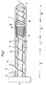
- FIG. 1 shows a schematic longitudinal section through a single-screw extruder 1.
- An extruder screw 6 is arranged within the extruder housing 2 and can be driven by a drive unit 5 about its longitudinal axis.
- the housing 2 has in the region of its upstream end a filling opening 3 for the material to be extruded, which leaves the extruder ready mixed and homogenized through the outlet opening 4.
- the extruder screw 6 has a screw geometry in the feed region 9 which is suitable for drawing the material fed through the filling opening 3 into the extruder and plasticizing it in a manner known per se.
- a pin cylinder area 7 is provided downstream of this feed area, in which two rows of pins 11 protrude radially through the extruder housing 2 in the direction of the screw axis into the processing space 14 of the extruder.
- the screw webs 12 are broken through in the pin plane in a known manner in order to avoid colliding with the pins 11.
- a transfer area 8 is arranged downstream of the pin cylinder area 7, in which in this exemplary embodiment the angles between the webs 18 of the extruder screw 6 and the webs 13 of the extruder housing 2 are greater than or equal to 105 °.
- the transfer area 8 can be divided into an inlet area and an outlet area, the two areas being separated from one another by the housing aisle with the greatest aisle depth.
- the number of gears in the inlet and outlet areas is constant, so that the number of webs in the inlet and outlet areas is independent of the gear cross-section of the housing or worm gears 16, 15.
- the last part of the process of the extruder screw 6 is formed by the pressure-increasing region 10, in which the screw geometry is selected such that the melt pressure can be raised to the necessary tool pressure in a known manner.
- the transfer area 8 could also be arranged upstream from the pin cylinder area 7, although the variant presented above produces the better mixing and homogenization results.
- the pin cylinder area also fulfills its mixing and homogenization task with more than two rows of pins. In terms of the cost-mix quality ratio, the pin cylinder area is best equipped with one to five rows of pins.
- the preferred length of the individual extruder areas is about 3 D for the feed area, 1.5 to 10 D, preferably 1.5 to 2 D for the pin barrel area, 2 to 2.5 D for the transfer area and approx 3 D for the pressure build-up area.
- additional process areas can also be arranged before, after or between the pin cylinder and transfer areas, e.g. Degassing or kneading areas.
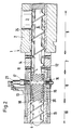
- FIG. 2 shows a pin transfer extruder 1 with throttle pins 11 in the transfer component.
- the filling area 9 of this extruder also corresponds to the usual cold feed extruder and has a ratio of screw length D to screw diameter of three.
- Downstream of the filling area 9 is an extruder section with a total length of 6 D in which the pin cylinder area 7 with two pin planes with extruder pins 11 arranged one behind the other is located.
- the transfer area is downstream of the pin cylinder area 7 8 with about 2 D and the pressure build-up area 9 with about 1.5 D in length.
- the temperature of the extruder barrel 2 is carried out in a known manner through temperature bores 19 in the housing wall 2.
- the transfer part of the extruder housing is locked in this embodiment as a housing bushing 20 in the housing 2.
- the pitch of the flights of the extruder screw and the transfer part bushing are chosen so that the webs between the screw and the bushing form an angle of equal to or more than 105 °. This advantageously results in the extrudate being subjected to an intensive shearing process as it passes through this transfer part, owing to the resulting large number of intersection points between screw and bush webs per screw rotation.
- the socket threads in the transfer part are not interrupted. Rather, they wind continuously and steadily from the inlet zone of the transfer part to its outlet zone in a roughly increasing or decreasing spiral around the imaginary longitudinal axis of the extruder.
- the screw core diameter increases from the max. Thread depth to the outside diameter, ie the thread volume of the screw 6 drops from the maximum value in the inlet area to zero.
- the volume of the bushing 20 has the opposite tendency.
- the passage volume effectively present for the extrudate is thus kept constant in the axial and radial transport directions. Due to these circumstances, there is inevitably a 100% extrudate exchange between screw 6 and cylinder liner 20.
- the flight volume of the screw 6 increases continuously and continuously decreases at the bushing 20, the total flight volume of the screw and bushing present for the extrudate again being kept constant.
- the number of flights in the inlet area and in the outlet area of the transfer area 8 is constant, as a result of which the number of screw and housing bush webs is independent of the screw and housing flight cross-sectional area.
- the machine has another process parameter, which can be freely selected and which extends the universality of the machine with regard to the processability of a wide range of different rubber compounds.
- a throttle element which has pins 17 distributed symmetrically on the circumference of the transfer component, which plunge radially into the uninterrupted gears of the transfer part bushing 20 and the gear volume of the bushing 20 in this range from the maximum value to can reduce to zero.
- This throttle pin 17 is among others attributable to the fact that for the first time it was possible to process rubber compound qualities with the pen transfer extruder that previously could not be processed with sufficient homogeneity with cold feed extrusion, also due to the use of specially optimized pen cylinder extruders. These are natural rubber grades, for example for the production of curb chains as well as tread compounds with the same base polymer for truck and EM tires.
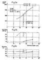
- FIGS. 3 ac show a graphical representation of test results which were achieved with an extruder according to the prior art (dashed curves) and a laboratory transfer pin extruder (solid curves) of comparable size.
- a natural rubber mixture NK 90-95 ML 1 + 4 (100 ° C) was used as extrudate, which as is known to be highly viscous and particularly difficult to process.
- a vertical line with hatching marks the speed of 25 revolutions per minute, up to which conventional extruders could process such a rubber mixture with acceptable quality.
- FIG. 3a the rubber output is plotted as a function of the screw speed
- FIG. 3b shows the melt temperature
- FIG. 3c the specific energy requirement per kg of extrudate as a function of the screw speed.
- FIG. 4 shows the extruder screw 6 in the transfer area 8 in one exemplary embodiment.
- the basically known increase or decrease in the cross-sectional area of the screw flight in the inlet or outlet area is brought about here only by the conical change in the core cross-section, that is to say the flight depth, of the screw.
- the number of gears in the inlet and outlet areas is different from one another, but is constant in the respective area. This has the consequence that the number of webs is independent of the cross-sectional area 22.
- the transfer screw in the area of the maximum extrudate transfer to the housing aisles for example in the area of the throttle pins 17, over Grooves 23 in the screw core.
- these grooves 23 connect the screw flights in the inlet and outlet area with one another, they do not allow material to be transported through them due to their small depth of approximately 1 mm and their small width of approximately 10 mm. Rather, the mixing performance of the transfer area can be improved even with difficult extrudates. This is done essentially by providing additional shaving edges through these grooves.
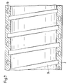
- FIG. 5 shows a schematic longitudinal section through a transfer housing bushing 20 which interacts with the transfer screw according to FIG. 4. It is also clear here that the number of housings is constant in the inlet and outlet areas, so that the number of housing webs remains independent of the housing cross-section.
- this design ensures excellent mixing quality with a very good self-cleaning effect, while, in particular in connection with the handling of the bushing component according to FIGS. 5 and 6, it becomes clear that the manufacturing effort for housing (and screw) gears of the same width is considerably reduced becomes.
- the proposed pin cylinder extruder can be used with or without throttle pins in the transfer part, although throttle pins should not be dispensed with in the optimal design.
- the adjustable throttle pins can also be arranged at the downstream end of the extruder, for example at the end of the pressure build-up area 10.
- FIG. 7 shows a longitudinal section through the extruder housing 2 with a housing groove 24 in the feed zone 8.
- the helical housing groove 24 has a depth of approximately 1 cm and a width of approximately 2.5 cm, although other groove depths and widths are also conceivable.
- the groove depth should not be selected greater than the groove width and the groove depth and groove width should not be less than 0.3 cm.
- the slope of the groove 24 corresponds approximately to the slope of the extruder screw in this area and extends over a length of approximately 3 to 5 screw diameters.
- the depth of the groove 24 slowly decreases at its ends until the housing inner wall is finally formed without grooves.
- the groove 24 turns in the opposite direction to the screw pitch (FIG. 2).
- the extrudate to be plasticized and mixed is provided with an enlarged housing wall surface, which improves the pulling behavior and thus the pulsation behavior of the extruder due to the increased adhesive effect.
- the groove walls can provide an enlarged heat transfer area, which, in particular in the case of a cooled extruder housing (see cooling duct 19 in FIG. 7), largely prevents undesired pre-plastification in the feed area of the extruder.
Landscapes
- Engineering & Computer Science (AREA)
- Mechanical Engineering (AREA)
- Extrusion Moulding Of Plastics Or The Like (AREA)
Claims (12)
- Extrudeuse pour la transformation et production de caoutchouc et de matières thermoplastiques comprenant un carter d'extrudeuse (2) avec une ouverture d'entrée et une ouverture de sortie (3, 4) et un entraînement (5) pour une vis d'extrudeuse (6) qui peut être tournée autour de son axe longitudinal dans la chambre de transformation (14) du carter (2) ainsi que des parties de cylindre à picots, Convert et d'étranglement,
caractérisée
en ce que l'extrudeuse (1) est pourvue de deux parties de mélangeage et d'homogénéisation (7, 8) arrangées l'une derrière l'autre,
en ce que l'une des parties est conçue comme partie de cylindre à picots (7) avec des picots (11) pénétrant radialement dans la chambre de transformation (14) du carter (2) et avec des filets de vis (12) intérrompus au niveau des picots (11),
en ce que l'autre partie est conçue comme partie Convert (8), dans laquelle la vis d'extrudeuse (6) présentant d'une zone d'entrée jusqu'à une zone de sortie une réduction continue du volume de filet jusqu'à zéro suivie d'une augmentation du volume de filet jusqu'à une valeur maximale et dans laquelle le carter d'extrudeuse (2) est pourvu de filets de carter ininterrompus qui, de la zone d'entrée jusqu'à la zone de sortie de la partie Convert, agrandissent leur volume de filet de zéro jusqu'à une valeur maximale et diminuent ensuite leur volume de filet jusqu'à zéro et dans laquelle les filets de carter vont en spirale autour d'une axe longitudinale théorique de l'extrudeuse,
en ce qu'au niveau du volume maximal des filets de carter sont arrangés des picots d'étranglement (17) ajustables radialement qui peuvent pénétrer à travers le carter (2) dans les filets de carter (16) ainsi que dans la chambre de transformation (14),
en ce que, dans les zones d'entrée et de sortie de la partie Convert (8), le nombre de filets et ainsi le nombre des hauts de filets de la vis (18) et du carter (13) sont indépendants de la superficie de filet du carter et de la vis (22) et
en ce que, dans la partie d'alimentation (9) de l'extrudeuse (1), la paroi intérieure du carter est pourvue d'une rainure hélicoïdale (24). - Extrudeuse selon revendication 1,
caractérisée en ce que
la partie de cylindre à picots (7) est arrangée en amont de la partie Convert (8). - Extrudeuse selon revendication 1,
caractérisée en ce que
l'extrudeuse est pourvue en amont des parties de mélangeage et d'homogénéisation (7, 8), d'une partie d'alimentation (9) et en aval d'une partie (10) servant à extruder la matière à la pression d'outil nécessaire. - Extrudeuse selon revendication 3,
caractérisée en ce que
dans le cas d'une longueur d'extrudeuse préférée de 10 diamètres de vis D, la longueur de la partie d'alimentation (9) est 3 D, de la partie de cylindre à picots (7) 1,5 à 2 D, de la partie à Convert (8) jusqu'à 2,5 D et de la zone de montée en pression (10) environ 3 D. - Extrudeuse selon les revendications 1 à 4,
caractérisée en ce que
la partie de cylindre à picots (7) comprend de préférence une à cinq rangées de picots (11). - Extrudeuse selon les revendications 1 à 5,
caractérisée en ce que
les picots d'étranglement ajustables (17) sont arrangés à l'extrémité en aval de l'extrudeuse (1). - Extrudeuse selon les revendications 1 et 6,
caractérisée en ce que
les picots d'étranglement (17) sont déplaçables au moyen de dispositifs d'ajustage (21) mécanique, pneumatique ou hydraulique. - Extrudeuse selon les revendications 1 à 7,
caractérisée en ce que
la vis d'extrudeuse (6) est pourvue dans la partie Convert (8) de rainures (23) plates et étroites qui relient les filets de vis (15) sur les côtés d'entrée et de sortie. - Extrudeuse selon les revendications 1 à 8,
caractérisée en ce que
la rainure (24) est dans le même sens par rapport au pas de la vis d'extrudeuse (6) dans la partie d'alimentation (9) du carter d'extrudeuse (12). - Extrudeuse selon revendication 9,
caractérisée en ce que
la largeur et la profondeur de la rainure (24) sont supérieres à 0,3 cm, la largeur de rainure étant de préférence 1 cm à 3 cm et la profondeur de rainure de 0,5 cm à 1,5 cm. - Extrudeuse selon les revendications 9 et 10,
caractérisée
en ce que la profondeur de rainure diminue lentement vers zéro aux extrémités et
en ce que la rainure (24) va en spirale sur une longueur de 1 à 3 diamètres de vis. - Extrudeuse selon les revendications 9 à 11,
caractérisée en ce que
le carter d'extrudeuse (2) peut être thermorégulé au moyen de canaux de thermorégulation (19).
Applications Claiming Priority (8)
| Application Number | Priority Date | Filing Date | Title |
|---|---|---|---|
| DE4039942 | 1990-12-14 | ||
| DE4039942A DE4039942C1 (fr) | 1990-12-14 | 1990-12-14 | |
| US07/693,224 US5141426A (en) | 1990-12-14 | 1991-04-29 | Degassing extruder |
| US07/693,237 US5147198A (en) | 1990-12-14 | 1991-04-29 | High performance extruder with a constant number of threads in the inlet and outlet regions of a transfer shearing section |
| US693221 | 1991-04-29 | ||
| US693224 | 1991-04-29 | ||
| US693237 | 1991-04-29 | ||
| US07/693,221 US5145352A (en) | 1990-12-14 | 1991-04-29 | Pin transfer extruder |
Publications (2)
| Publication Number | Publication Date |
|---|---|
| EP0490361A1 EP0490361A1 (fr) | 1992-06-17 |
| EP0490361B1 true EP0490361B1 (fr) | 1994-07-13 |
Family
ID=27435088
Family Applications (1)
| Application Number | Title | Priority Date | Filing Date |
|---|---|---|---|
| EP91121254A Expired - Lifetime EP0490361B1 (fr) | 1990-12-14 | 1991-12-11 | Extrudeuse pour extrudat difficilement miscible |
Country Status (7)
| Country | Link |
|---|---|
| EP (1) | EP0490361B1 (fr) |
| JP (1) | JPH0639901A (fr) |
| CN (1) | CN1035547C (fr) |
| AT (1) | ATE108364T1 (fr) |
| CA (1) | CA2057603C (fr) |
| DE (2) | DE4120016C1 (fr) |
| RU (1) | RU2008223C1 (fr) |
Cited By (1)
| Publication number | Priority date | Publication date | Assignee | Title |
|---|---|---|---|---|
| US6284192B1 (en) | 1998-11-02 | 2001-09-04 | Corning Incorporated | Extruding electrode material |
Families Citing this family (8)
| Publication number | Priority date | Publication date | Assignee | Title |
|---|---|---|---|---|
| US7390118B2 (en) * | 2004-10-15 | 2008-06-24 | Husky Injection Molding Systems Ltd. | Extruder assembly |
| DE102009040047A1 (de) * | 2009-09-04 | 2011-03-17 | Bayer Materialscience Ag | Verfahren zur Einarbeitung von Feststoffen in Polymere |
| CN102114699B (zh) * | 2011-01-24 | 2013-06-05 | 无锡市江南橡塑机械有限公司 | 一种混合型销钉机筒冷喂料挤出机 |
| KR20140034227A (ko) | 2011-05-13 | 2014-03-19 | 엔에프엠 웰딩 엔지니어스 인코포레이티드 | 개선된 탈수 기계 및 프로세스 |
| EP3053725A1 (fr) * | 2015-02-06 | 2016-08-10 | LANXESS Deutschland GmbH | Vis de gavage |
| JP7118971B2 (ja) | 2016-12-21 | 2022-08-16 | ビーエーエスエフ ソシエタス・ヨーロピア | 一軸押出機および一軸押出機の使用ならびに一軸押出機を用いて高吸収性ポリマの形態を変化させる方法 |
| DE102019119533B3 (de) * | 2019-07-18 | 2020-09-24 | Gneuss Gmbh | Extruder zur viskositätserhöhenden Aufbereitung von aufschmelzbaren Polymeren |
| CN113752520B (zh) * | 2021-09-01 | 2023-04-14 | 青岛科技大学 | 一种螺杆 |
Family Cites Families (11)
| Publication number | Priority date | Publication date | Assignee | Title |
|---|---|---|---|---|
| BE551763A (fr) * | 1961-05-15 | 1900-01-01 | ||
| US3632255A (en) * | 1969-01-10 | 1972-01-04 | Uniroyal Inc | Extrusion apparatus |
| US3613160A (en) * | 1969-11-24 | 1971-10-19 | Baker Perkins Inc | Variable bypass orifice for continuous mixer |
| DE2235784C3 (de) * | 1972-07-21 | 1986-01-09 | Uniroyal Englebert Reifen GmbH, 5100 Aachen | Einschnecken-Extruder zum Mischen und Homogenisieren von hochviskosen Kautschukmischungen und hochviskosen Thermoplasten |
| US4178104A (en) * | 1972-07-21 | 1979-12-11 | Uniroyal, Ag | Method and apparatus for mixing viscous materials |
| CA1074780A (fr) * | 1976-07-14 | 1980-04-01 | Frenkel C-D Aktiengesellschaft | Malaxeur transporteur a cylindre et a vis a rainures helicoidales de section variable et de sens opposes |
| CA1077922A (fr) * | 1976-07-14 | 1980-05-20 | Paul Meyer | Melangeur helicoidal a gorges multiples et tambour fixe |
| DE3003615C2 (de) * | 1980-02-01 | 1984-03-29 | Hermann Berstorff Maschinenbau Gmbh, 3000 Hannover | Schneckenstrangpresse mit Stiftzylinder |
| DE8110512U1 (de) * | 1981-04-07 | 1981-10-29 | Paul Kiefel GmbH Maschinenfabrik, 6520 Worms | Einzugsbuchse fuer einschnecken-extruder" |
| DE3133708C2 (de) * | 1981-08-26 | 1986-07-03 | Semen Il'ič Gdalin | Extruder zur Verarbeitung von Polymerwerkstoffen |
| GB8808107D0 (en) * | 1988-04-07 | 1988-05-11 | Meyer P | Method & means for improving uniformity-performance of cold feed rubber extruders |
-
1991
- 1991-06-18 DE DE4120016A patent/DE4120016C1/de not_active Expired - Lifetime
- 1991-12-07 CN CN91111462A patent/CN1035547C/zh not_active Expired - Fee Related
- 1991-12-11 AT AT91121254T patent/ATE108364T1/de not_active IP Right Cessation
- 1991-12-11 EP EP91121254A patent/EP0490361B1/fr not_active Expired - Lifetime
- 1991-12-11 DE DE59102181T patent/DE59102181D1/de not_active Expired - Fee Related
- 1991-12-13 CA CA002057603A patent/CA2057603C/fr not_active Expired - Fee Related
- 1991-12-13 JP JP3330957A patent/JPH0639901A/ja not_active Withdrawn
- 1991-12-13 RU SU915010423A patent/RU2008223C1/ru active
Cited By (1)
| Publication number | Priority date | Publication date | Assignee | Title |
|---|---|---|---|---|
| US6284192B1 (en) | 1998-11-02 | 2001-09-04 | Corning Incorporated | Extruding electrode material |
Also Published As
| Publication number | Publication date |
|---|---|
| EP0490361A1 (fr) | 1992-06-17 |
| RU2008223C1 (ru) | 1994-02-28 |
| DE59102181D1 (de) | 1994-08-18 |
| CN1062492A (zh) | 1992-07-08 |
| JPH0639901A (ja) | 1994-02-15 |
| CN1035547C (zh) | 1997-08-06 |
| ATE108364T1 (de) | 1994-07-15 |
| CA2057603C (fr) | 1996-09-24 |
| CA2057603A1 (fr) | 1992-06-15 |
| DE4120016C1 (fr) | 1992-07-02 |
Similar Documents
| Publication | Publication Date | Title |
|---|---|---|
| EP0490058B1 (fr) | Extrudeuse à haut rendement | |
| DE2731301A1 (de) | Vorrichtung zum kontinuierlichen mischen | |
| CH633990A5 (de) | Vorrichtung zum kontinuierlichen mischen von materialien. | |
| DE19928870C2 (de) | Einschnecken-Extruder | |
| DE3206325A1 (de) | "mehrwellige, kontinuierlich arbeitende misch- und knetmaschine fuer plastifizierbare massen mit ineinandergreifenden, gleichsinnig drehenden schnecken konstanten achsabstandes" | |
| DE1502335B2 (de) | Schneckenstrangprese fuer die verarbeitung von kunststoff | |
| DE2548490A1 (de) | Schneckenextruder | |
| DE3854984T2 (de) | Schneckenstrangpresse | |
| EP0171756A2 (fr) | Extrudeuse à vis | |
| EP0490361B1 (fr) | Extrudeuse pour extrudat difficilement miscible | |
| DE10114727B4 (de) | Schneckenelement für gleichsinnig drehende Mehrschneckenextruder | |
| EP0490362B1 (fr) | Extrudeuse à haut rendement à nombre de filets constant dans la zone d'entrée et dans la zone de sortie d'un élément de cisaillement par transfert | |
| EP0513593A2 (fr) | Dispositif pour l'extrusion de mélanges matières plastiques et caoutchouc | |
| DE1729145C3 (de) | Schneckenstrangpresse für Kunststoff | |
| DE102006014692B3 (de) | Schneckenelement | |
| EP0490360B1 (fr) | Procédé et extrudeuse pour le traitement et la fabrication de matières caoutchouteuses ou plastiques | |
| DE4137969C1 (fr) | ||
| DE10354172A1 (de) | Extruder | |
| DE4209179C1 (fr) | ||
| DE1912459A1 (de) | Verfahren und Vorrichtung zur Verarbeitung von hochviskosen Werkstoffen,insbesondere Kautschukmischungen in Einschnecken-Extrudern | |
| DE4114610C2 (de) | Stifttransferextruder | |
| DE69717417T2 (de) | Extrusionsvorrichtung | |
| DE2533195C3 (de) | Kontinuierlicher Doppelschneckenextruder | |
| EP0627980A1 (fr) | Extrudeuse a vis | |
| DE3839621A1 (de) | Planetwalzenextruder |
Legal Events
| Date | Code | Title | Description |
|---|---|---|---|
| PUAI | Public reference made under article 153(3) epc to a published international application that has entered the european phase |
Free format text: ORIGINAL CODE: 0009012 |
|
| 17P | Request for examination filed |
Effective date: 19920408 |
|
| AK | Designated contracting states |
Kind code of ref document: A1 Designated state(s): AT CH DE FR GB IT LI NL SE |
|
| 17Q | First examination report despatched |
Effective date: 19930924 |
|
| ITF | It: translation for a ep patent filed | ||
| GRAA | (expected) grant |
Free format text: ORIGINAL CODE: 0009210 |
|
| AK | Designated contracting states |
Kind code of ref document: B1 Designated state(s): AT CH DE FR GB IT LI NL SE |
|
| REF | Corresponds to: |
Ref document number: 108364 Country of ref document: AT Date of ref document: 19940715 Kind code of ref document: T |
|
| REF | Corresponds to: |
Ref document number: 59102181 Country of ref document: DE Date of ref document: 19940818 |
|
| ET | Fr: translation filed | ||
| GBT | Gb: translation of ep patent filed (gb section 77(6)(a)/1977) |
Effective date: 19940901 |
|
| EAL | Se: european patent in force in sweden |
Ref document number: 91121254.6 |
|
| PLBE | No opposition filed within time limit |
Free format text: ORIGINAL CODE: 0009261 |
|
| STAA | Information on the status of an ep patent application or granted ep patent |
Free format text: STATUS: NO OPPOSITION FILED WITHIN TIME LIMIT |
|
| 26N | No opposition filed | ||
| PGFP | Annual fee paid to national office [announced via postgrant information from national office to epo] |
Ref country code: AT Payment date: 19961209 Year of fee payment: 6 |
|
| PGFP | Annual fee paid to national office [announced via postgrant information from national office to epo] |
Ref country code: NL Payment date: 19961219 Year of fee payment: 6 |
|
| PGFP | Annual fee paid to national office [announced via postgrant information from national office to epo] |
Ref country code: CH Payment date: 19961230 Year of fee payment: 6 |
|
| PGFP | Annual fee paid to national office [announced via postgrant information from national office to epo] |
Ref country code: DE Payment date: 19970906 Year of fee payment: 7 |
|
| PGFP | Annual fee paid to national office [announced via postgrant information from national office to epo] |
Ref country code: GB Payment date: 19971202 Year of fee payment: 7 |
|
| PG25 | Lapsed in a contracting state [announced via postgrant information from national office to epo] |
Ref country code: AT Free format text: LAPSE BECAUSE OF NON-PAYMENT OF DUE FEES Effective date: 19971211 |
|
| PGFP | Annual fee paid to national office [announced via postgrant information from national office to epo] |
Ref country code: FR Payment date: 19971212 Year of fee payment: 7 |
|
| PGFP | Annual fee paid to national office [announced via postgrant information from national office to epo] |
Ref country code: SE Payment date: 19971218 Year of fee payment: 7 |
|
| PG25 | Lapsed in a contracting state [announced via postgrant information from national office to epo] |
Ref country code: LI Free format text: LAPSE BECAUSE OF NON-PAYMENT OF DUE FEES Effective date: 19971231 Ref country code: CH Free format text: LAPSE BECAUSE OF NON-PAYMENT OF DUE FEES Effective date: 19971231 |
|
| PG25 | Lapsed in a contracting state [announced via postgrant information from national office to epo] |
Ref country code: NL Free format text: LAPSE BECAUSE OF NON-PAYMENT OF DUE FEES Effective date: 19980701 |
|
| REG | Reference to a national code |
Ref country code: CH Ref legal event code: PL |
|
| NLV4 | Nl: lapsed or anulled due to non-payment of the annual fee |
Effective date: 19980701 |
|
| PG25 | Lapsed in a contracting state [announced via postgrant information from national office to epo] |
Ref country code: GB Free format text: LAPSE BECAUSE OF NON-PAYMENT OF DUE FEES Effective date: 19981211 |
|
| PG25 | Lapsed in a contracting state [announced via postgrant information from national office to epo] |
Ref country code: SE Free format text: LAPSE BECAUSE OF NON-PAYMENT OF DUE FEES Effective date: 19981212 |
|
| GBPC | Gb: european patent ceased through non-payment of renewal fee |
Effective date: 19981211 |
|
| PG25 | Lapsed in a contracting state [announced via postgrant information from national office to epo] |
Ref country code: FR Free format text: LAPSE BECAUSE OF NON-PAYMENT OF DUE FEES Effective date: 19990831 |
|
| REG | Reference to a national code |
Ref country code: FR Ref legal event code: ST |
|
| PG25 | Lapsed in a contracting state [announced via postgrant information from national office to epo] |
Ref country code: DE Free format text: LAPSE BECAUSE OF NON-PAYMENT OF DUE FEES Effective date: 19991001 |
|
| PG25 | Lapsed in a contracting state [announced via postgrant information from national office to epo] |
Ref country code: IT Free format text: LAPSE BECAUSE OF NON-PAYMENT OF DUE FEES;WARNING: LAPSES OF ITALIAN PATENTS WITH EFFECTIVE DATE BEFORE 2007 MAY HAVE OCCURRED AT ANY TIME BEFORE 2007. THE CORRECT EFFECTIVE DATE MAY BE DIFFERENT FROM THE ONE RECORDED. Effective date: 20051211 |