EP0489534B1 - Procédé d'extrusion et extrudeuse pour la fabrication d'un tuyau en résine phénolique - Google Patents
Procédé d'extrusion et extrudeuse pour la fabrication d'un tuyau en résine phénolique Download PDFInfo
- Publication number
- EP0489534B1 EP0489534B1 EP91310942A EP91310942A EP0489534B1 EP 0489534 B1 EP0489534 B1 EP 0489534B1 EP 91310942 A EP91310942 A EP 91310942A EP 91310942 A EP91310942 A EP 91310942A EP 0489534 B1 EP0489534 B1 EP 0489534B1
- Authority
- EP
- European Patent Office
- Prior art keywords
- die
- flow path
- screw
- extrusion
- inlet
- Prior art date
- Legal status (The legal status is an assumption and is not a legal conclusion. Google has not performed a legal analysis and makes no representation as to the accuracy of the status listed.)
- Expired - Lifetime
Links
- 238000001125 extrusion Methods 0.000 title claims description 93
- KXGFMDJXCMQABM-UHFFFAOYSA-N 2-methoxy-6-methylphenol Chemical compound [CH]OC1=CC=CC([CH])=C1O KXGFMDJXCMQABM-UHFFFAOYSA-N 0.000 title claims description 30
- 229920001568 phenolic resin Polymers 0.000 title claims description 30
- 239000005011 phenolic resin Substances 0.000 title claims description 30
- 239000000463 material Substances 0.000 claims description 32
- 238000010438 heat treatment Methods 0.000 claims description 14
- 238000000034 method Methods 0.000 claims description 14
- 230000006835 compression Effects 0.000 claims description 10
- 238000007906 compression Methods 0.000 claims description 10
- 238000007493 shaping process Methods 0.000 claims description 3
- 229920005989 resin Polymers 0.000 description 26
- 239000011347 resin Substances 0.000 description 26
- 230000000052 comparative effect Effects 0.000 description 10
- 238000010276 construction Methods 0.000 description 9
- 241000239290 Araneae Species 0.000 description 8
- 229920001187 thermosetting polymer Polymers 0.000 description 7
- 238000004519 manufacturing process Methods 0.000 description 5
- 238000000465 moulding Methods 0.000 description 3
- 238000002844 melting Methods 0.000 description 2
- 230000008018 melting Effects 0.000 description 2
- 229920000642 polymer Polymers 0.000 description 2
- 229920005992 thermoplastic resin Polymers 0.000 description 2
- -1 thermosetting resin Chemical compound 0.000 description 2
- 239000000654 additive Substances 0.000 description 1
- 238000005452 bending Methods 0.000 description 1
- 239000003795 chemical substances by application Substances 0.000 description 1
- 239000003086 colorant Substances 0.000 description 1
- 238000000748 compression moulding Methods 0.000 description 1
- 239000002270 dispersing agent Substances 0.000 description 1
- 239000000945 filler Substances 0.000 description 1
- 239000004088 foaming agent Substances 0.000 description 1
- 239000011521 glass Substances 0.000 description 1
- 238000001746 injection moulding Methods 0.000 description 1
- 238000004898 kneading Methods 0.000 description 1
- 239000004033 plastic Substances 0.000 description 1
- 229920003023 plastic Polymers 0.000 description 1
- 238000011417 postcuring Methods 0.000 description 1
- 239000000126 substance Substances 0.000 description 1
- 230000008961 swelling Effects 0.000 description 1
- 229920003002 synthetic resin Polymers 0.000 description 1
- 239000000057 synthetic resin Substances 0.000 description 1
- 229920001169 thermoplastic Polymers 0.000 description 1
- 239000002562 thickening agent Substances 0.000 description 1
- 238000001721 transfer moulding Methods 0.000 description 1
Images

Classifications
-
- B—PERFORMING OPERATIONS; TRANSPORTING
- B29—WORKING OF PLASTICS; WORKING OF SUBSTANCES IN A PLASTIC STATE IN GENERAL
- B29C—SHAPING OR JOINING OF PLASTICS; SHAPING OF MATERIAL IN A PLASTIC STATE, NOT OTHERWISE PROVIDED FOR; AFTER-TREATMENT OF THE SHAPED PRODUCTS, e.g. REPAIRING
- B29C48/00—Extrusion moulding, i.e. expressing the moulding material through a die or nozzle which imparts the desired form; Apparatus therefor
- B29C48/25—Component parts, details or accessories; Auxiliary operations
- B29C48/30—Extrusion nozzles or dies
- B29C48/32—Extrusion nozzles or dies with annular openings, e.g. for forming tubular articles
- B29C48/33—Extrusion nozzles or dies with annular openings, e.g. for forming tubular articles with parts rotatable relative to each other
-
- B—PERFORMING OPERATIONS; TRANSPORTING
- B29—WORKING OF PLASTICS; WORKING OF SUBSTANCES IN A PLASTIC STATE IN GENERAL
- B29C—SHAPING OR JOINING OF PLASTICS; SHAPING OF MATERIAL IN A PLASTIC STATE, NOT OTHERWISE PROVIDED FOR; AFTER-TREATMENT OF THE SHAPED PRODUCTS, e.g. REPAIRING
- B29C48/00—Extrusion moulding, i.e. expressing the moulding material through a die or nozzle which imparts the desired form; Apparatus therefor
- B29C48/022—Extrusion moulding, i.e. expressing the moulding material through a die or nozzle which imparts the desired form; Apparatus therefor characterised by the choice of material
-
- B—PERFORMING OPERATIONS; TRANSPORTING
- B29—WORKING OF PLASTICS; WORKING OF SUBSTANCES IN A PLASTIC STATE IN GENERAL
- B29C—SHAPING OR JOINING OF PLASTICS; SHAPING OF MATERIAL IN A PLASTIC STATE, NOT OTHERWISE PROVIDED FOR; AFTER-TREATMENT OF THE SHAPED PRODUCTS, e.g. REPAIRING
- B29C48/00—Extrusion moulding, i.e. expressing the moulding material through a die or nozzle which imparts the desired form; Apparatus therefor
- B29C48/03—Extrusion moulding, i.e. expressing the moulding material through a die or nozzle which imparts the desired form; Apparatus therefor characterised by the shape of the extruded material at extrusion
- B29C48/09—Articles with cross-sections having partially or fully enclosed cavities, e.g. pipes or channels
-
- B—PERFORMING OPERATIONS; TRANSPORTING
- B29—WORKING OF PLASTICS; WORKING OF SUBSTANCES IN A PLASTIC STATE IN GENERAL
- B29C—SHAPING OR JOINING OF PLASTICS; SHAPING OF MATERIAL IN A PLASTIC STATE, NOT OTHERWISE PROVIDED FOR; AFTER-TREATMENT OF THE SHAPED PRODUCTS, e.g. REPAIRING
- B29C48/00—Extrusion moulding, i.e. expressing the moulding material through a die or nozzle which imparts the desired form; Apparatus therefor
- B29C48/25—Component parts, details or accessories; Auxiliary operations
- B29C48/78—Thermal treatment of the extrusion moulding material or of preformed parts or layers, e.g. by heating or cooling
- B29C48/80—Thermal treatment of the extrusion moulding material or of preformed parts or layers, e.g. by heating or cooling at the plasticising zone, e.g. by heating cylinders
- B29C48/83—Heating or cooling the cylinders
- B29C48/832—Heating
-
- B—PERFORMING OPERATIONS; TRANSPORTING
- B29—WORKING OF PLASTICS; WORKING OF SUBSTANCES IN A PLASTIC STATE IN GENERAL
- B29K—INDEXING SCHEME ASSOCIATED WITH SUBCLASSES B29B, B29C OR B29D, RELATING TO MOULDING MATERIALS OR TO MATERIALS FOR MOULDS, REINFORCEMENTS, FILLERS OR PREFORMED PARTS, e.g. INSERTS
- B29K2061/00—Use of condensation polymers of aldehydes or ketones or derivatives thereof, as moulding material
- B29K2061/04—Phenoplasts
-
- B—PERFORMING OPERATIONS; TRANSPORTING
- B29—WORKING OF PLASTICS; WORKING OF SUBSTANCES IN A PLASTIC STATE IN GENERAL
- B29L—INDEXING SCHEME ASSOCIATED WITH SUBCLASS B29C, RELATING TO PARTICULAR ARTICLES
- B29L2023/00—Tubular articles
- B29L2023/22—Tubes or pipes, i.e. rigid
Definitions
- the present invention relates to an extrusion method used for obtaining a phenolic resin pipe and an extruder used in effecting said method.
- thermosetting resin As the method for molding a thermosetting resin, there are known compression molding, transfer molding, injection molding and extrusion. Various apparatuses suitable for respective methods are in use.
- plunger extrusion As one of the methods for molding a thermosetting resin, plunger extrusion is generally used.
- Japanese Patent Application Laid-Open No. 83155/1973 and Plastics Vol. 25, No. 3, p. 47 describe the production by plunger extrusion, of long shaped articles of simple configuration such as round bar, pipe and the like.
- Plunger extrusion makes it difficult to produce an extrudate of homogeneous quality and gives low productivity because it employs a high extrusion pressure in the mold cavity of the plunger extruder used and is conducted intermittently.
- extrusion using a so-called screw type equipment is disclosed in, for example, Japanese Patent Application Laid-Open No. 23661/1979 or Japanese Patent Application Laid-Open No. 18949/1974.
- Such extrusion uses an extruder wherein a thermosetting resin is kneaded and melt in an extrusion unit and the molten resin is extruded from the unit and introduced into a die unit through an adapter or the like in a time as short as possible to prevent the progress of thermosetting reaction and shaped into a final form.
- the resin heated and melt in a cylinder is introduced into a die through an adapter and shaped into a final form.
- the resin is squeezed and then expanded around a mandrel fixed by a spider; thus, the resin makes complex flow. Consequently, stagnation of flow takes place easily, giving rise to localized curing reaction, or slight fluctuation in pressure and/or temperature causes rapid appearance of curing reaction.
- a very large extrusion pressure is required and a special extruder capable of generating such a pressure is needed.
- U.K. Patent No. 2089717 discloses an extruder which corresponds to the extruder of Japanese Patent Application Laid-Open No. 23661/1979 minus the adapter and the spider and which comprises a screw, a cylinder, a die and a mandrel, wherein the mandrel is provided on the extension of the screw axis.
- This extruder was proposed for production of thermoplastic resin pipe.
- This extruder relates to an extrusion technique for obtaining a pipe of balanced strengths by utilizing the property of molten thermoplastic polymer that their molecules, when flowing through a small path at a high speed, are orientated to the flow direction and by orientating the polymer molecules to different directions at the inner and outer layers of the pipe.
- thermosetting resin shaped articles With respect to obtaining thermosetting resin shaped articles.
- An object of the present invention is to provide an extrusion method and an extruder used for obtaining a phenolic resin pipe at excellent productivity.
- Another object of the present invention is to provide an extrusion method capable of producing a shaped article having no quality problems such as (a) spider marks and (b) welds generated owing to the presence of spider.
- Another object of the present invention is to provide an extrusion method capable of producing a pipe having an outside diameter smaller than 20 mm.
- Another object of the present invention is to provide an extrusion method capable of producing a shaped article having no quality problem caused by the partial curing at the die inlet when a torpedo is used.
- Still other object of the present invention is to provide a phenolic resin pipe having excellent homogeneity.
- Fig. 1 illustrates a preferred extruder used in the extrusion method of the present invention.
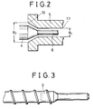
- Fig. 2 is an enlarged view showing the inlet of the die in the extruder of Fig. 1.
- Fig. 3 is an example of a detachable mandrel.
- an extrusion method for obtaining a phenolic resin pipe which method uses an extruder comprising a screw consisting of a feed zone, a compression zone and a metering zone, a cylinder having heating means corresponding to the feed zone, the compression zone and the metering zone, a die fitted to the front end of the cylinder, having a heating means, and a mandrel inserted into a through-hole formed in the screw along the screw axis and protruding into the die along the screw axis, or firmly fitted to the front end of the screw, and which method comprises shaping and extruding a phenolic resin material in the die in a state that the material before extrusion is cured to a certain extent and the material after extrusion can retain its own shape.
- This extrusion method has made it possible to produce a pipe having an outside diameter smaller than 20 mm which had been impossible to produce by the technique disclosed in U.S. Patent No. 4797242, and further can produce many different pipes in small amounts advantageously by using different dies and different mandrels.
- the extruder used in the present invention can be any of a single-screw extruder, a twin-screw extruder and a multi-screw extruder.
- the double-screw extruder and the multi-screw extruder must be those in which the screw front is integrated into a monoaxial state.
- the extruder used in the present invention may have a gas vent and/or a special kneading means between the feed zone and the metering zone.
- the extruder may further have, at the front end of the die, a unit having a cross section very slightly smaller than the die outlet so as to be able to control the back pressure applied to the resin being shaped and extruded.
- the screw is a type generally used in the extrusion of synthetic resin. It may be full-flighted or may have a torpedo shape having a smooth zone at the front end.
- the front end shape of the screw may be columnar or conical.
- a phenolic resin material fed from a hopper 1 is heated and melt in a cylinder 2 having heaters 3, sent forward by the rotation of a screw 4, and introduced into a die 5 in a molten state.
- the material at the die inlet is in a molten and homogeneous state so as to be adapted to the change of the flow path, by controlling the temperature of the heating zone of the cylinder communicating with the die inlet at 120-145°C, preferably 125-140°C. When the temperature of said heating zone is lower than 120°C, the material at the die inlet may not be in a molten and homogeneous state.
- the material When the temperature is higher than 145°C, the material may cause partial curing and may find the smooth change of the flow path difficult. Thereafter, the material is heated in the die to 150-200°C, preferably 150-185°C, whereby the curing of the material is promoted and the material is shaped and extruded as a shaped article in a state that the material after extrusion is cured so as to be able to retain its own shape.
- the heating temperature in the die is appropriately controlled depending upon the pipe thickness and extrusion speed employed. When the heating temperature is lower than 150°C, the curing reaction of the material does not proceed sufficiently. Meanwhile, the heating to higher than 200°C is unnecessary because the phenolic resin is sufficiently cured at temperatures up to 200°C.
- the cross section of the resin inlet 10 of the die is the same as the cross section formed by the cylinder and the screw front, and the cross section of the resin outlet 11 is the same as that of desired product.
- the resin flow path in the die is made so as to allow for smooth change from the inlet to the outlet.
- the inclination of the outer periphery of the flow path portion 8′ from the die inlet 10 to the starting point of the uniform flow path portion having the same cross section as the die outlet 11 is not larger than 35°, preferably not larger than 30° to the axis of the screw.
- the change in flow path in the portion 8′ is rapid, making the resin flow non-smooth.
- the mandrel 6 is, at one end, inserted into a through-hole 9 in the screw along the screw axis and, at other end, protruding into the die along the screw axis. Accordingly, no spider as used for supporting a mandrel in ordinary dies is necessary, whereby the flow of material resin is not hindered at all.
- the resin introduced into the die is sent forward through the constantly changing flow path portion in a molten state; in the uniform flow path portion having the same cross section as the die outlet, is shaped and cured; and is extruded as a shaped article 7.
- the length of the uniform flow path portion having the same cross section as the die outlet must be determined depending upon the combination of wall thickness of article, viscosity and curing rate of material used, other extrusion conditions, etc., but can be appropriately selected in a range of usually 1D to 30D (D is the inside diameter of die), preferably 5D to 25D, more preferably 5D to 20D.
- the shaped article obtained by the extrusion method of the present invention retains its own shape already right after extrusion and, by controlling the extrusion conditions, can be sufficiently shaped and cured to such an extent that it undergoes no easy deformation by an external force. Therefore, it causes no warpage, bending, swelling, etc. when put into actual usages.
- a post-curing treatment may be conducted.
- the treatment can increase the thermal deformation temperature of shaped article and allows the use of the resulting article at temperatures of, for example, 200°C or more.
- the phenolic resin material used in the present invention may comprise, as necessary, additives generally used in molding of phenolic resin, such as filler, releasing agent, thickener, coloring agent, dispersing agent, foaming agent, curing accelerator and the like.
- the phenolic resin material may further comprise other polymers and organic or inorganic fibrous substances such as glass and the like.
- the material preferably gives a flow amount of 0.05-25 g when subjected to the flow test by extrusion method according to JIS K 6911.
- test mold temperature 140°C
- extrusion pressure 150 kgf/cm2.
- An extruder having a cylinder diameter of 30 mm and an L/D ratio of 12 was used.
- the cylinder contained a full-flight screw having a feed zone 7D, a compression zone 1D, a metering zone 4D and a compression ratio of 1.5.
- a mandrel having an outer diameter of 5 mm was inserted into the screw along the screw axis.
- To the front end of the cylinder was fitted a die having a diameter of 9 mm, a length of 200 mm and a flow path construction as shown in Table 1. Using this extruder, extrusion was effected.
- the temperatures of the cylinder zones and the die were set as follows.
- the screw rotation was set at 8 rpm.
- a pipe having an outside diameter of 9 mm and a wall thickness of 2 mm could be obtained continuously by extrusion.
- the properties of the pipe are shown in Table 1.
- Extrusion was effected in the same manner as in Example 1 except that the outside diameter of the mandrel was changed to 8 mm, the diameter and length of the die were changed to 12 mm and 300 mm, respectively, and the rotation of the screw was changed to 12 rpm.
- Extrusion was effected in the same manner as in Example 1 except that there was used a phenolic resin material giving a flow amount of 0.2 g in the flow test, the outside diameter of the mandrel was changed to 11 mm, the diameter and length of the die were changed to 16 mm and 300 mm, respectively, and the rotation of the screw was changed to 15 rpm.
- Extrusion was effected in the same manner as in Example 1 except that there was used a phenolic resin material giving a flow amount of 18 g in the flow test, the outside diameter of the mandrel was changed to 18 mm, the diameter and length of the die were changed to 24 mm and 400 mm, respectively, and the rotation of the screw was changed to 20 rpm.
- a phenolic resin material giving a flow amount of 4 g in the flow test was used.
- An extruder having a cylinder diameter of 50 mm and an L/D ratio of 12 was used.
- the cylinder contained a full-flight screw having a feed zone 7D, a compression zone 1D, a metering zone 4D and a compression ratio of 1.5.
- a mandrel having an outer diameter of 22 mm was inserted into the screw along the screw axis.
- To the front end of the cylinder was fitted a die having a diameter of 39 mm, a length of 508 mm and a flow path construction as shown in Table 1. Using the above resin material and extruder, extrusion was effected.
- the temperatures of the cylinder zones and the die were set as follows.
- the screw rotation was set at 10 rpm.
- a pipe having an outside diameter of 39 mm and a wall thickness of 8.5 mm could be obtained continuously by extrusion.
- the properties of the pipe are shown in Table 1.
- Extrusion was effected in the same manner as in Example 5 except that the outside diameter of the mandrel was changed to 32 mm.
- Extrusion was effected in the same manner as in Example 1 except that the outside diameter of the mandrel was changed to 2 mm, the diameter and length of the die were changed to 6 mm and 300 mm, respectively, and the rotation of the screw was changed to 6 rpm. Extrusion load increased suddenly in about 5 minutes from the start of extrusion, and the continuation of extrusion became impossible.
- the construction of the die flow path is shown in Table 1.
- Extrusion was effected in the same manner as in Example 1 except that the outside diameter of the mandrel was changed to 37 mm, the diameter and length of the die were changed to 45 mm and 508 mm, respectively, the rotation of the screw was changed to 25 rpm, and the temperatures of the cylinder C4 zone and the die were changed to 135°C and 175°C, respectively.
- Extrusion load increased suddenly in about 4 minutes from the start of extrusion, and the continuation of extrusion became impossible.
- the construction of the die flow path is shown in Table 1.
- Extrusion was effected in the same manner as in Example 3 except that the outside diameter of the mandrel was changed to 6 mm, the diameter and length of the die were changed to 8 mm and 300 mm, respectively, the rotation of the screw was changed to 6 rpm, and the temperatures of the cylinder C4 zone and the die were changed to 125°C and 175°C.
- Extrusion load increased in about 5 minutes from the start of extrusion, and the continuation of extrusion became impossible.
- the construction of the die flow path is shown in Table 1.
- Extrusion was effected in the same manner as in Example 5 except that the outside diameter of the mandrel was changed to 1 mm, the diameter and length of the die were changed to 45 mm and 508 mm, respectively, the rotation of the screw was changed to 20 rpm, the temperatures of the cylinder C5 zone and the die were changed to 140°C and 160°C and a phenolic resin material giving a flow amount of 5 g was used. Extrusion load increased suddenly in about 5 minutes from the start of extrusion, and the continuation of extrusion became impossible. The construction of the die flow path is shown in Table 1.
- Extrusion was effected in the same manner as in Example 1 except that the inclination angle of the flow path-changing portion of the die was changed as shown in Table 1. Extrusion load was not stable and it was impossible to obtain a pipe of homogeneous quality.
- Extrusion was effected in the same manner as in Example 1 except that a phenolic resin material giving a flow amount of 35 g was used.
- the properties of the pipe obtained are shown in Table 1. Continuous extrusion was possible but the pipe surface had no gloss and was rough.
- Extrusion was effected in the same manner as in Example 1 except that the temperature of the cylinder C4 zone was changed to 110°C. Extrusion load fluctuated largely and soon became high, which made extrusion impossible.
- Extrusion was effected in the same manner as in Example 1 except that the temperature of the cylinder C4 zone was changed to 155°C and the temperature of the die was changed to 175°C. Extrusion load increased suddenly in about 15 minutes from the start of extrusion and the continuation of extrusion became impossible.
- Extrusion was effected in the same manner as in Example 1 except that the temperature of the cylinder C4 zone was changed to 125°C and the temperature of the die was changed to 140°C.
- the properties of the pipe obtained are shown in Table 1. The pipe had insufficient curing and, when heated to, for example, 135°C, was deformed even by a small force.
Claims (8)
- Procédé d'extrusion, pour obtenir un tuyau de résine phénolique, par utilisation d'une extrudeuse comprenant une vis, un cylindre, une filière et un mandrin, le mandrin étant inséré dans un trou débouchant formé dans la vis, le long de l'axe de la vis, et pénétrant dans la filière selon l'axe de la vis ; la filière satisfaisant aux formules suivantes :

- Procédé d'extrusion selon la revendication 1, dans lequel la quantité écoulée de la résine phénolique, lorsqu'on la soumet à l'essai d'écoulement par le procédé d'extrusion selon JIS K 6911, est de 0,05 à 25 g.
- Procédé d'extrusion selon la revendication 1, dans lequel la température de la zone de chauffage du cylindre, à l'arrière de l'entrée de la filière, est ajustée à 125-140°C et la température de la filière est ajustée à 150-185°C.
- Procédé d'extrusion selon la revendication 1, dans lequel la filière satisfait aux formules suivantes :

- Procédé d'extrusion selon la revendication 1, dans lequel l'inclinaison du pourtour extérieur de la portion de voie de passage de la filière, de l'entrée de la filière au point de départ de la portion de voie de passage uni forme ayant la même, section transversale que la sortie de la filière n'est pas supérieure à 30° relativement à l'axe de la vis.
- Procédé d'extrusion selon la revendication 1, dans lequel la longueur de la portion de voie de passage uniforme de la filière ayant la même section transversale que la sortie de la filière est 1 D à 30 D, où D est le diamètre intérieur de la filière.
- Procédé d'extrusion selon la revendication 6, dans lequel la longueur de la portion de voie de passage uniforme de la filière ayant la même section transversale que la sortie de la filière est 5 D à 20 D.
- Extrudeuse, pour l'obtention d'un tuyau de résine phénolique, comprenant une vis constituée d'une zone d'alimentation, d'une zone de compression et d'une zone de pompage, un cylindre ayant un dispositif de chauffage correspondant à la zone d'alimentation, la zone de compression et la zone de pompage, une filière montée à l'extrémité avant du cylindre ayant un dispositif de chauffage et un mandrin inséré dans un trou débouchant formé dans la vis, le long de l'axe de la vis, et pénétrant dans la filière selon l'axe de la vis, la filière satisfaisant aux formules suivantes :

Applications Claiming Priority (2)
| Application Number | Priority Date | Filing Date | Title |
|---|---|---|---|
| JP321190/90 | 1990-11-27 | ||
| JP32119090 | 1990-11-27 |
Publications (2)
| Publication Number | Publication Date |
|---|---|
| EP0489534A1 EP0489534A1 (fr) | 1992-06-10 |
| EP0489534B1 true EP0489534B1 (fr) | 1996-05-08 |
Family
ID=18129794
Family Applications (1)
| Application Number | Title | Priority Date | Filing Date |
|---|---|---|---|
| EP91310942A Expired - Lifetime EP0489534B1 (fr) | 1990-11-27 | 1991-11-27 | Procédé d'extrusion et extrudeuse pour la fabrication d'un tuyau en résine phénolique |
Country Status (6)
| Country | Link |
|---|---|
| US (1) | US5204039A (fr) |
| EP (1) | EP0489534B1 (fr) |
| JP (1) | JP2500277B2 (fr) |
| KR (1) | KR940009900B1 (fr) |
| CA (1) | CA2056131C (fr) |
| DE (1) | DE69119375T2 (fr) |
Families Citing this family (10)
| Publication number | Priority date | Publication date | Assignee | Title |
|---|---|---|---|---|
| DE4332698A1 (de) * | 1993-09-25 | 1995-03-30 | Huels Chemische Werke Ag | Verfahren zur kontinuierlichen Herstellung von fließ-, schäum- und härtfähigen Phenolresolharz-Mischungen |
| US5976432A (en) * | 1996-09-09 | 1999-11-02 | Plymouth Products, Inc. | Method and apparatus for the continuous extrusion of block elements |
| US5823668A (en) * | 1997-05-29 | 1998-10-20 | Spirex Corporation | Extruder and extrusion screw therefor |
| US6905667B1 (en) * | 2002-05-02 | 2005-06-14 | Zyvex Corporation | Polymer and method for using the polymer for noncovalently functionalizing nanotubes |
| DE10251152B4 (de) * | 2002-10-31 | 2007-10-04 | Rehau Ag + Co. | Extrudieren von peroxidischen vernetzbaren Formteilen aus Kunststoff |
| JP4684304B2 (ja) * | 2008-01-23 | 2011-05-18 | 日東電工株式会社 | 樹脂発泡体の製造方法及び樹脂発泡体 |
| US7975833B2 (en) * | 2008-07-15 | 2011-07-12 | General Electric Company | Material handling system and method |
| JP6451471B2 (ja) * | 2015-04-10 | 2019-01-16 | オムロン株式会社 | スイッチ装置 |
| DE102017106097B4 (de) | 2017-03-21 | 2022-08-11 | Technische Universität Chemnitz | Extrudervorrichtung und Extrusionsverfahren |
| FI128422B (en) * | 2019-01-11 | 2020-04-30 | Teknologian Tutkimuskeskus Vtt Oy | Single screw extruders and extrusion procedure |
Family Cites Families (26)
| Publication number | Priority date | Publication date | Assignee | Title |
|---|---|---|---|---|
| US3003194A (en) * | 1959-06-16 | 1961-10-10 | Perma Tubes Ltd | Method of producing bituminous glass-fiber pipe |
| US3292213A (en) * | 1964-09-23 | 1966-12-20 | Dow Chemical Co | Tube extrusion apparatus |
| US3317956A (en) * | 1964-12-22 | 1967-05-09 | Hedwin Corp | Mixing device for extruding apparatus |
| US3387331A (en) * | 1965-07-27 | 1968-06-11 | Rexall Drug Chemical | Apparatus for extruding seamless plastic tubing |
| DE2135549A1 (de) * | 1971-07-16 | 1973-01-25 | Krupp Gmbh | Kunststoffstrangpressen |
| JPS5217057B2 (fr) * | 1972-02-09 | 1977-05-13 | ||
| JPS5436614B2 (fr) * | 1972-06-06 | 1979-11-10 | ||
| FR2216097B1 (fr) * | 1973-02-07 | 1976-04-09 | Pont A Mousson | |
| US3870451A (en) * | 1973-04-30 | 1975-03-11 | Beloit Corp | Apparatus for extruding foamed thermoplastic material |
| GB1453516A (en) * | 1974-01-18 | 1976-10-27 | Dainippon Toryo Kk | Method for continuous extrusion moulding of thermosetting resins |
| US4001368A (en) * | 1974-02-08 | 1977-01-04 | Dai Nippon Toryo Co., Ltd. | Method for continuous extrusion molding of thermosetting resins |
| JPS5423661A (en) * | 1977-07-22 | 1979-02-22 | Mitsubishi Chem Ind Ltd | Continuous extrusion molding of thermosetting resin |
| US4240782A (en) * | 1979-10-17 | 1980-12-23 | The Gates Rubber Company | Extruder head for making elastomer-fiber composite hose |
| IT1195267B (it) * | 1980-04-15 | 1988-10-12 | Abc Ist Biolog Chem Spa | Derivati teofillinmetildiossolanici,procedimento per la loro preparazione e relative composizioni farmaceutiche |
| FI803964L (fi) * | 1980-12-19 | 1982-06-20 | Proplast Oy | Extruder foer framstaellning av plastroer |
| JPH0611514B2 (ja) * | 1983-03-29 | 1994-02-16 | 三井東圧化学株式会社 | 熱硬化性樹脂の押出成形方法 |
| NO173690C (no) * | 1983-03-29 | 1994-01-19 | Mitsui Toatsu Chemicals | Fremgangsmaate ved fremstilling av roer ved ekstruderingsforming av en termoherdende harpiks |
| JPS60245898A (ja) * | 1984-05-22 | 1985-12-05 | Mitsui Petrochem Ind Ltd | 超高分子量ポリエチレン製フレキシブルチユ−ブ、溶融流動性の悪い熱可塑性樹脂製チユ−ブの製造方法及びその製造装置 |
| JPS6116828A (ja) * | 1984-07-03 | 1986-01-24 | Mitsui Toatsu Chem Inc | 熱硬化性樹脂のスクリユ−型押出成形装置 |
| JPS6149823A (ja) * | 1984-08-16 | 1986-03-11 | Mitsui Toatsu Chem Inc | 熱硬化性樹脂の押出成形方法 |
| JPS6155151A (ja) * | 1984-08-27 | 1986-03-19 | Mitsui Toatsu Chem Inc | 熱硬化性樹脂成形材料 |
| JPS6155152A (ja) * | 1984-08-27 | 1986-03-19 | Mitsui Toatsu Chem Inc | 熱硬化性樹脂成形材料 |
| JPS6164749A (ja) * | 1984-09-07 | 1986-04-03 | Mitsui Toatsu Chem Inc | フェノール樹脂の連続押出成形方法 |
| JPS6164748A (ja) * | 1984-09-07 | 1986-04-03 | Mitsui Toatsu Chem Inc | フェノール樹脂の連続押出成形方法 |
| DE3676393D1 (de) * | 1985-08-12 | 1991-02-07 | Mitsui Petrochemical Ind | Blasfolie und verfahren und vorrichtung zur herstellung derselben. |
| US4798696A (en) * | 1987-05-08 | 1989-01-17 | A/S Sonnichsen Rorvalseverket | Method for extrusion of plastic tubes, and an apparatus for carrying out said method |
-
1991
- 1991-11-15 JP JP3300588A patent/JP2500277B2/ja not_active Expired - Lifetime
- 1991-11-25 CA CA002056131A patent/CA2056131C/fr not_active Expired - Fee Related
- 1991-11-25 US US07/797,056 patent/US5204039A/en not_active Expired - Fee Related
- 1991-11-26 KR KR1019910021291A patent/KR940009900B1/ko not_active IP Right Cessation
- 1991-11-27 EP EP91310942A patent/EP0489534B1/fr not_active Expired - Lifetime
- 1991-11-27 DE DE69119375T patent/DE69119375T2/de not_active Expired - Fee Related
Also Published As
| Publication number | Publication date |
|---|---|
| KR940009900B1 (ko) | 1994-10-18 |
| DE69119375D1 (de) | 1996-06-13 |
| JP2500277B2 (ja) | 1996-05-29 |
| US5204039A (en) | 1993-04-20 |
| EP0489534A1 (fr) | 1992-06-10 |
| DE69119375T2 (de) | 1996-11-21 |
| CA2056131A1 (fr) | 1992-05-28 |
| CA2056131C (fr) | 1994-06-28 |
| KR920009538A (ko) | 1992-06-25 |
| JPH054268A (ja) | 1993-01-14 |
Similar Documents
| Publication | Publication Date | Title |
|---|---|---|
| US3956438A (en) | Process for extruding a partially foamed thermoplastic product | |
| CN100493885C (zh) | 超临界流体辅助高分子材料挤出成型机 | |
| US3782870A (en) | Apparatus for extruding a partially foamed thermoplastic product | |
| EP1448354B1 (fr) | Appareil d'extrusion de tubes a parois minces | |
| US5863480A (en) | Process for making a filler reinforced thermoplastic composites having biaxially oriented components | |
| EP0489534B1 (fr) | Procédé d'extrusion et extrudeuse pour la fabrication d'un tuyau en résine phénolique | |
| US6210616B1 (en) | Profile extrusion of thermoplastic composites with high filler content | |
| JPH0611514B2 (ja) | 熱硬化性樹脂の押出成形方法 | |
| JPH0510211B2 (fr) | ||
| JPS6116828A (ja) | 熱硬化性樹脂のスクリユ−型押出成形装置 | |
| CN209937615U (zh) | 用于制造过氧化物交联聚乙烯管材的螺杆式塑料挤出装置 | |
| JPH07304086A (ja) | フェノール系樹脂中空棒状体の連続成型方法および装置 | |
| JPS60110420A (ja) | 合成樹脂複合管の製造方法及び装置 | |
| JPS6141521A (ja) | 熱硬化性樹脂の押出成形方法 | |
| US6592793B1 (en) | Apparatus and method for extruding pencils | |
| KR100451844B1 (ko) | 압출성형플라스틱제조품의제조방법및장치와,이플라스틱제조품 | |
| JPH0582285B2 (fr) | ||
| JPH10109349A (ja) | スクリュー押出機 | |
| JPH0467494B2 (fr) | ||
| JPS6144622A (ja) | 熱硬化性樹脂のスクリユ−型押出成形装置 | |
| JP2002113766A (ja) | ポリエチレン管の製造方法およびこの製造方法に用いる金型 | |
| JPH0565335B2 (fr) | ||
| JPH0548169B2 (fr) | ||
| CN117644636A (zh) | 一种超高分子量聚合物挤出成型方法及成型设备 | |
| JPS6155151A (ja) | 熱硬化性樹脂成形材料 |
Legal Events
| Date | Code | Title | Description |
|---|---|---|---|
| PUAI | Public reference made under article 153(3) epc to a published international application that has entered the european phase |
Free format text: ORIGINAL CODE: 0009012 |
|
| AK | Designated contracting states |
Kind code of ref document: A1 Designated state(s): DE FR GB NL |
|
| 17P | Request for examination filed |
Effective date: 19921007 |
|
| 17Q | First examination report despatched |
Effective date: 19940728 |
|
| GRAH | Despatch of communication of intention to grant a patent |
Free format text: ORIGINAL CODE: EPIDOS IGRA |
|
| GRAA | (expected) grant |
Free format text: ORIGINAL CODE: 0009210 |
|
| AK | Designated contracting states |
Kind code of ref document: B1 Designated state(s): DE FR GB NL |
|
| REF | Corresponds to: |
Ref document number: 69119375 Country of ref document: DE Date of ref document: 19960613 |
|
| ET | Fr: translation filed | ||
| PLBE | No opposition filed within time limit |
Free format text: ORIGINAL CODE: 0009261 |
|
| STAA | Information on the status of an ep patent application or granted ep patent |
Free format text: STATUS: NO OPPOSITION FILED WITHIN TIME LIMIT |
|
| 26N | No opposition filed | ||
| REG | Reference to a national code |
Ref country code: GB Ref legal event code: 732E |
|
| REG | Reference to a national code |
Ref country code: FR Ref legal event code: TP |
|
| NLS | Nl: assignments of ep-patents |
Owner name: MITSUI CHEMICALS, INC. |
|
| PGFP | Annual fee paid to national office [announced via postgrant information from national office to epo] |
Ref country code: FR Payment date: 20001110 Year of fee payment: 10 |
|
| PGFP | Annual fee paid to national office [announced via postgrant information from national office to epo] |
Ref country code: DE Payment date: 20001120 Year of fee payment: 10 |
|
| PGFP | Annual fee paid to national office [announced via postgrant information from national office to epo] |
Ref country code: GB Payment date: 20001122 Year of fee payment: 10 |
|
| PGFP | Annual fee paid to national office [announced via postgrant information from national office to epo] |
Ref country code: NL Payment date: 20001130 Year of fee payment: 10 |
|
| PG25 | Lapsed in a contracting state [announced via postgrant information from national office to epo] |
Ref country code: GB Free format text: LAPSE BECAUSE OF NON-PAYMENT OF DUE FEES Effective date: 20011127 |
|
| REG | Reference to a national code |
Ref country code: GB Ref legal event code: IF02 |
|
| PG25 | Lapsed in a contracting state [announced via postgrant information from national office to epo] |
Ref country code: NL Free format text: LAPSE BECAUSE OF NON-PAYMENT OF DUE FEES Effective date: 20020601 |
|
| PG25 | Lapsed in a contracting state [announced via postgrant information from national office to epo] |
Ref country code: DE Free format text: LAPSE BECAUSE OF NON-PAYMENT OF DUE FEES Effective date: 20020702 |
|
| GBPC | Gb: european patent ceased through non-payment of renewal fee |
Effective date: 20011127 |
|
| PG25 | Lapsed in a contracting state [announced via postgrant information from national office to epo] |
Ref country code: FR Free format text: LAPSE BECAUSE OF NON-PAYMENT OF DUE FEES Effective date: 20020730 |
|
| NLV4 | Nl: lapsed or anulled due to non-payment of the annual fee |
Effective date: 20020601 |
|
| REG | Reference to a national code |
Ref country code: FR Ref legal event code: ST |
|
| REG | Reference to a national code |
Ref country code: FR Ref legal event code: ST |