EP0489502A2 - Multiple blade set strip apparatus for cable and wire - Google Patents
Multiple blade set strip apparatus for cable and wire Download PDFInfo
- Publication number
- EP0489502A2 EP0489502A2 EP91310242A EP91310242A EP0489502A2 EP 0489502 A2 EP0489502 A2 EP 0489502A2 EP 91310242 A EP91310242 A EP 91310242A EP 91310242 A EP91310242 A EP 91310242A EP 0489502 A2 EP0489502 A2 EP 0489502A2
- Authority
- EP
- European Patent Office
- Prior art keywords
- wire
- sections
- blades
- sheathing
- section
- Prior art date
- Legal status (The legal status is an assumption and is not a legal conclusion. Google has not performed a legal analysis and makes no representation as to the accuracy of the status listed.)
- Granted
Links
- 238000000034 method Methods 0.000 claims abstract description 20
- 238000006073 displacement reaction Methods 0.000 claims abstract description 10
- 230000033001 locomotion Effects 0.000 claims description 15
- 238000000926 separation method Methods 0.000 claims description 9
- 230000000694 effects Effects 0.000 claims description 7
- 230000035515 penetration Effects 0.000 claims description 6
- 241000237858 Gastropoda Species 0.000 claims description 5
- 230000004044 response Effects 0.000 claims description 4
- 230000000063 preceeding effect Effects 0.000 claims 1
- 230000001681 protective effect Effects 0.000 claims 1
- 230000007246 mechanism Effects 0.000 description 3
- 239000002184 metal Substances 0.000 description 2
- 230000005540 biological transmission Effects 0.000 description 1
- 230000008878 coupling Effects 0.000 description 1
- 238000010168 coupling process Methods 0.000 description 1
- 238000005859 coupling reaction Methods 0.000 description 1
Images


Classifications
-
- H—ELECTRICITY
- H02—GENERATION; CONVERSION OR DISTRIBUTION OF ELECTRIC POWER
- H02G—INSTALLATION OF ELECTRIC CABLES OR LINES, OR OF COMBINED OPTICAL AND ELECTRIC CABLES OR LINES
- H02G1/00—Methods or apparatus specially adapted for installing, maintaining, repairing or dismantling electric cables or lines
- H02G1/12—Methods or apparatus specially adapted for installing, maintaining, repairing or dismantling electric cables or lines for removing insulation or armouring from cables, e.g. from the end thereof
- H02G1/1202—Methods or apparatus specially adapted for installing, maintaining, repairing or dismantling electric cables or lines for removing insulation or armouring from cables, e.g. from the end thereof by cutting and withdrawing insulation
- H02G1/1248—Machines
- H02G1/1251—Machines the cutting element not rotating about the wire or cable
- H02G1/1253—Machines the cutting element not rotating about the wire or cable making a transverse cut
- H02G1/1256—Machines the cutting element not rotating about the wire or cable making a transverse cut using wire or cable-clamping means
-
- Y—GENERAL TAGGING OF NEW TECHNOLOGICAL DEVELOPMENTS; GENERAL TAGGING OF CROSS-SECTIONAL TECHNOLOGIES SPANNING OVER SEVERAL SECTIONS OF THE IPC; TECHNICAL SUBJECTS COVERED BY FORMER USPC CROSS-REFERENCE ART COLLECTIONS [XRACs] AND DIGESTS
- Y10—TECHNICAL SUBJECTS COVERED BY FORMER USPC
- Y10T—TECHNICAL SUBJECTS COVERED BY FORMER US CLASSIFICATION
- Y10T29/00—Metal working
- Y10T29/49—Method of mechanical manufacture
- Y10T29/49002—Electrical device making
- Y10T29/49117—Conductor or circuit manufacturing
-
- Y—GENERAL TAGGING OF NEW TECHNOLOGICAL DEVELOPMENTS; GENERAL TAGGING OF CROSS-SECTIONAL TECHNOLOGIES SPANNING OVER SEVERAL SECTIONS OF THE IPC; TECHNICAL SUBJECTS COVERED BY FORMER USPC CROSS-REFERENCE ART COLLECTIONS [XRACs] AND DIGESTS
- Y10—TECHNICAL SUBJECTS COVERED BY FORMER USPC
- Y10T—TECHNICAL SUBJECTS COVERED BY FORMER US CLASSIFICATION
- Y10T29/00—Metal working
- Y10T29/51—Plural diverse manufacturing apparatus including means for metal shaping or assembling
- Y10T29/5136—Separate tool stations for selective or successive operation on work
- Y10T29/5137—Separate tool stations for selective or successive operation on work including assembling or disassembling station
- Y10T29/5139—Separate tool stations for selective or successive operation on work including assembling or disassembling station and means to sever work prior to disassembling
- Y10T29/514—Separate tool stations for selective or successive operation on work including assembling or disassembling station and means to sever work prior to disassembling comprising means to strip insulation from wire
-
- Y—GENERAL TAGGING OF NEW TECHNOLOGICAL DEVELOPMENTS; GENERAL TAGGING OF CROSS-SECTIONAL TECHNOLOGIES SPANNING OVER SEVERAL SECTIONS OF THE IPC; TECHNICAL SUBJECTS COVERED BY FORMER USPC CROSS-REFERENCE ART COLLECTIONS [XRACs] AND DIGESTS
- Y10—TECHNICAL SUBJECTS COVERED BY FORMER USPC
- Y10T—TECHNICAL SUBJECTS COVERED BY FORMER US CLASSIFICATION
- Y10T29/00—Metal working
- Y10T29/51—Plural diverse manufacturing apparatus including means for metal shaping or assembling
- Y10T29/5193—Electrical connector or terminal
Definitions
- This invention relates generally to wire or cable severing, as well as stripping sheathing from severed wire sections; and more particularly, it concerns unusual advantages, method and apparatus to effect severing of a wire or cable into two sections, and stripping of sheathing off ends of both sections, with minimal motions of severing and stripping elements and in minimum time.
- the method involves processing the wire into sections as byw displacing the wire endwise along an axis to a first position; severing the wire thereby to form wire forward and rearward sections, the forward section having a rearward end portion, and the rearward section having a forward end portion; and stripping sheathing from the forward section rearward portion and from the rearward section forward portion thereby to expose wire cores at those end portions.
- the cutter means typically may include three blade pairs, each pair including two blades located at opposite sides of the axis, both blades of one pair being displaced toward the wire to sever the wire, and both blades of the remaining two pairs being displaced toward the wire sections to strip sheathing from the rearward and forward portions during controlled endwise displacement of the sections.
- Both blades of one pair are typically displaced into overlapping relation to sever the wire, and both blades of each of the remaining two pairs are displaced to cut only into opposite sides of the sheathing and to strip sheathing from the end portions of the sections as the sections are displaced endwise simultaneously.
- Another object is to displace the two sections endwise, thereby to displace wire incorporating one of the sections to the first position.
- the method further includes the step of separating the sections axially relatively endwise after the step of severing of the wire and prior to the step of stripping of sheathing from the section end portions.
- the method may include the step of further separating the sections axially relatively endwise after the blades of the remaining two pairs have been displaced toward the wire sections to cut into the sheathing, thereby to pull sheathing slugs off the wire end portions to expose the wire end cores.
- Yet another object is to guide displacement of the wire endwise along the axis, at locations between blade pairs; and in this regard, both of the forward and rearward sections may be so guided.
- a further object is to carry out separation of the forward and rearward wire sections by advancing one section and retracting the other section, relative to the one blade pair; and the method typically involves carrying out further separation of the sections by further advancing the one section and further retracting the other section, relative to each one blade pair.
- Apparatus for processing wire into sections, as referred to, and to strip sheathing from the sections to expose wire core ends basically includes:
- each pair of conveyors defining a wire gripping zone, such zones maintained in alignment with the wire sections during separation of the latter.
- Means is further provided to maintain one conveyor of each pair laterally displaced relatively toward the other conveyor of the pair to clamp the wire sections between the conveyors of the pairs during the further separation of the wire sections, and operating the conveyor pairs in endless relation to effect the relative separation in a longitudinal direction.
- the blades of the first cutter means typically have positions of relative overlap to sever the wire, in response to operation of the first drive means; and the blades of the second and third cutter means typically have positions of penetration only into the sheathing of the section end portions and to such depths as to enable stripping of the sheathing end portions in response to the controllable driving of the conveyor means.
- novel and unusually effective apparatus is provided to advance the three sets of blades simultaneously toward the wire to first sever, and subsequently strip wire sheathing, at multiple axial locations, wire sections being axially displaced while severing blades are closed, and prior to closure of sheath stripping blades toward the sections.
- Figs. 1 a --1 f show in diagramsatic form the positions of both wire severing and sheathing stripping blades, during various steps in the wire processing procedure or method.
- the "wire" 10 (meant to also refer to cable) has a metal core 11 a and a tubular sheathing 11 b about the core.
- the wire is shown extending axially longitudinally in Figs. 1 a --1 f , the axis being located at 12.
- First cutter means is provided to include, or may be considered to include, multiple blades. See for example the two wire-cutting blades 13 a and 13 b of a first set, located or carried for movement laterally toward and away from the wire axis 12.
- Second and third cutter means are also provided, for sheathing stripping, and each may be considered to include multiple blades located for movement toward and away from the axis 12. See for example the second set of two blades 16 a and 16 b , and the third set of two blades 17 a and 17 b .
- Blades 16 a and 16 b are located or considered to be controllably simultaneously displaced, as by drive 18, laterally oppositely, toward one another (see arrows 19 a and 19 b in Fig. 1 d ), the drive also operable to retract the blades 16 a and 16 b away from one another.
- the blades 17 a and 17 b are located or carried to be controllably displaced, simultaneously, laterally oppositely toward one another (see arrows 20 a and 20 b in Fig. 1 d ), and drive 18 may be used for this purpose.
- blades 16 a and 16 b may be displaced toward one another at the same time and to the same extent as blades 17 a and 17 b are displaced toward another, as is clear from Fig. 1 d .
- the latter shows that the blades 16 a and 16 b , and 17 a and 17 b , do not sever the wire but may closely approach the wire while cutting into sheathing 11 for stripping purposes.
- Figs. 9-11 show the blades 16 a and 16 b to have V-shape, as do wire severing blades 13 a and 13 b , and blades 17 a and 17 b .
- Hote edges 16 a ′ and 16 a ⁇ and 16 b ′ and 16 b ⁇ (of blades 16 a and 16 b ) cutting into the sheathing in Fig. 10 a to approach the wire core from four sides for efficient stripping, while leaving the core uncut.
- Similar functioning of blade edges 17 a ′ and 17 a ⁇ , and 17 b ′ and 17 b ⁇ also takes place, as in Fig. 1 d .
- Fig. 1 a shows displacement of the wire axially endwise and longitudinally, as by a conveyor means 21 a to the first position as shown.
- Fig. 1 b shows the step of severing the wire thereby to form wire forward and rearward sections 10 a and 10 b , the blades 13 a and 13 b being advanced laterally to accomplish complete severing at locus 22, as shown.
- wire forward section 10 a has a rearward end portion 10 aa
- the wire rearward section 10 b has a forward end portion 10 bb .
- Fig. 1 c shows the step of controllably separating the two sections 10 a and 10 b axially endwise oppositely, as to the positions shown, in which the end portions 10 aa and 10 bb are spaced from the closed-together blades 13 a and 13 b .
- Wire drives 21 a and 21 b are controllably operated to engage and separate the two sections 10 a and 10 b , as indicated in Figs. 1 a and 1 c .
- Fig. 1 d shows a sub-step included within the step of stripping sheathing from the forward section rearward portion and from the rearward section forward portion thereby to expose wire ends at the portions.
- blades 16 a and 16 b are simultaneously advanced laterally oppositely, as to blade edge positions described above as respects Fig. 10 a
- blades 17 a and 17 b are also simultaneously advanced laterally oppositely (as to the same extent if such stripping is to be equal for each wire section).
- blades 13 a and 13 b now extend in laterally overlapping condition due to operation of drives 15 and 18 as one, i.e., equal rightward lateral displacement for blades 13 a , 16 a and 17 a , and equal leftward lateral displacement for blades 13 b , 16 b and 17 b ; however, they may be separately driven so as not to extend in such relation, as shown.
- Blades 13 a , 16 a and 17 a may be connected together to move rightwardly to equal extent; and blades 13 b , 16 b and 17 b may also be connected together to move leftwardly as one, for extreme simplicity.
- Fig. 1 e shows operation of the wire drives to further endwise separate the wire sections 10 a and 10 b so as to pull or strip two sheathing end portions 11 b ′ and 11 b ⁇ from the wire sections 10 a and 10 b , thereby to expose the wire core end portions 11 a ′ and 11 a ⁇ .
- the stripped sheathing end portions 11 b ′ and 11 b ⁇ , or slugs, are allowed to drop out from between the pairs of guides 24 and 25 which may be split, as shown, to provide slug drop-out openings, and may be movable to facilitate such drop out.
- Fig. 1 f shows all blades laterally retracted and the wire rearward section 10 b fully advanced into position corresponding to Fig. 1 a position for controlled length endwise positioning to be processed, as in Figs. 1 b --1 e to provide an exposed core end at its opposite end.
- controlled length wires or cables, with exposed core lengths at each end of each wire, is efficiently and rapidly and controllably provided. See master control 35 to control all the driving, as described, and to be described.
- a frame is provided, as at 40-44 and 44a, to mount two conveyors 45 and 46, which may be considered as included within the wire drives 30 and 31, as mentioned.
- Such conveyors may include two reawardly positioned endless belts 47 and 48, and two forwardly positioned endless belts 49 and 50.
- the belts provide stretches, as at 47′ and 48′, which are adapted to sidewise flatly grip the wire 10 (and specifically the wire rearward section 10 b ) for endwise advancement and retraction, as during separation of the sections 10 a and 10 b in Fig. 1 c ; and stretches 49′ and 50′ are adapted to sidewise grip the wire 10 (and specifically the wire forward section 10 a ) for endwise advancement and retraction.
- the belts 47 and 48 are driven to advance or retract the wire section 10 a as from a drive motor 52 (see Fig. 4).
- the output shaft 53 of the motor drives belt 54, as via a pulley 55, and belt 54 drives shafts 56 and 57.
- Shaft 56 drives another shaft 58, through gearing 59 and 60, to drive shaft 58 and upper conveyor belt 47 clockwise; whereas lower shaft 57 and lower belt 48 are driven counterclockwise in Fig. 2. This drives the wire forwardly; whereas when motor 52 is reversed, the wire is driven rearwardly. Additional axles or shafts for the conveyor belts 47 and 48 appear at 58 a and 57 a .
- Fig. 2 shows conveyor rotors 60 and 61, and 62 and 63. These carry the belts 47 and 48. Axles 58 a and 57 a are driven by drive belts 64 and 65 extending between pulleys on the shafts 58 and 58 a , and 57 and 57 a , as shown. Accordingly, when the belt stretches 47′ and 48′ are closed against opposite sides of the wire 10, and the motor 52 is operating, the wire is displaced endwise.
- Means is provided to move the conveyor belt stretches 47′ and 48′ toward one another to clutch the wire, and away from one another to de-clutch the wire. See for example in Figs. 3-5 the motor or drive 66 carried by a frame part 67 to rotate a vertical screw shaft 68, as via motor output shaft 69, pulley 70, belt 71, and pulley 72 on the screw shaft 68.
- the screw shaft has screw thread engagement at 33 and 34 with frame members 75 and 76.
- Frame member 76 supports the ends of shafts 58 and 58 a , via member extension 76 a , as at 58′ and 58 a ′; whereas frame member 75 supports the ends of shafts 57 and 57 a , via member extension 75 a , as at 57′ and 57 a ′.
- Screw threading interfit at 74 is oppositely "handed" relative to threading interfit at 73, so that when shaft 68 is rotated in one direction about its axis, the frame members 75 and 76 are displaced toward one another, whereby conveyor stretches 47′ and 48′ may clamp the wire; and when the shaft 68 is rotated in the opposite direction about its axis, the members 75 and 76 are displaced away from each other, and the wire is de-clutched.
- the bearing supports at 80 and 81 for shafts 58 and 57 are made loose enough to accommodate such up/down movement of those shafts at the conveyor belt drive locations. Note also couplings at 110 and 111.
- Tension springs 90 and 91 are provided (see Fig. 5) between fixed frame structure 92 and shoulders 76 a ′ on 76 a to yieldably urge the structures 76 and 76 a , and the belt stretch 47′ downwardly; and similarly, tension springs 93 and 94 are provided between fixed frame structure 95 and shoulder 75 a ′ on 75 to yieldably urge the structure 75 and 75 a and the belt stretch 48′ upwardly. This provides clearance "take-up" for better control of wire gripping or clamping.
- the forward conveyor unit 46 embodies conveyor belt drive and up/down movement the same as described in connection with unit 45 in Figs. 3-5.
- the drive motor 52 a for driving the belt stretches 49′ and 50′ forwardly and reversely is seen in Fig. 3, as is the motor 66 a to control belt clamping of the forward wire section.
- Mechanism between the motors 52 a and 66 a , and the respective forward conveyor belts 49 and 50, is the same as above described mechanism between motors 52 and 66 and the respective rearward conveyor belts 47 and 48; however, the motors 52 and 51 a are typically operated simultaneously, either to drive the wire or wire sections forwardly, as in Figs. 1 a and 1 f , or to drive the wire sections endwise oppositely, as in Figs. 1 c and 1 e .
- a master control to control all drives, in a pre-programmed manner, is seen at 125.
- the wire severing blades 13 a and 13 b are fully laterally retracted, as are the wire sheathing stripping blades 16 a and 16 b .
- Blades 17 a and 17 b are in axial alignment with blades 16 a and 16 b , and are not shown. Note V-angled blade edges 13 a ′ and 13 a ⁇ , and blade edges 13 b ′ and 13 b ⁇ .
- the blades 13 a , 16 a and 17 a at one side of the wire 10 are interconnected by axially extending carrier rod 80; and the blades 13 b , 16 b and 17 b at the opposite ends of the wire are interconnected by axially extending carrier rod 81, laterally spaced from rod 80.
- Rods 80 and 81 are relatively movable laterally toward one another to effect wire severing, as by blades 13 a and 13 b (see Fig. 9 and also Fig. 1 b ).
- Rods 80 and 81 are further laterally movable toward one another to effect penetration of the blade edges 16 a ′ and 16 a ⁇ , and 16 b ′ and 16 b ⁇ into the sheathing (as in Figs.
- the wire forward and rearward sections 10 a and 10 b are separated as in Fig. 1 e to endwise strip the slugs 10 aa and 10 bb , off the wire cores, as also seen in Fig. 11. Dropping of the slug is also seen in Fig. 11, as is lowering of a wire guide lower sector B of guide 11 b ⁇ , to release the slug.
- the upper guide sector is shown at A.
- a drive 130 is operable to lower and raise sector B..
- a laterally extending lead screw 90 is rotatable by n drive motor 91, carried by frame part 92. See connecting shaft 93.
- nuts 94 and 95 on the screw threads travel axially oppositely (see arrows 96 and 97) to move rod 80 to the right and rod 81 to the left, as in Figs. 9 and 10.
- a pair of parallel lead screws 90 may be utilized for these purposes, as see in Fig.
Landscapes
- Removal Of Insulation Or Armoring From Wires Or Cables (AREA)
- Processing Of Terminals (AREA)
Abstract
Description
- This invention relates generally to wire or cable severing, as well as stripping sheathing from severed wire sections; and more particularly, it concerns unusual advantages, method and apparatus to effect severing of a wire or cable into two sections, and stripping of sheathing off ends of both sections, with minimal motions of severing and stripping elements and in minimum time.
- There is continual need for equipment capable of severing wire or cable into sections, and also capable of rapidly and efficiently stripping sheathing off ends of those sections. It is desirable that these functions be carried out as a wire or cable travels along generally the same axis, i.e., progresses forwardly, and that multiple wire and cable sections of selected length be produced, each having its opposite ends stripped of sheathing, to expose bare metal core wire at each end. Further, it is desirable that simple, radial and axial stripping adjustments be achieved upon multiple wire sections.
- It is a major object of the invention to provide apparatus and method meeting the above need. The word "wire" will be used to include cable within its scope, and vice versa.
- Basically, the method involves processing the wire into sections as byw displacing the wire endwise along an axis to a first position; severing the wire thereby to form wire forward and rearward sections, the forward section having a rearward end portion, and the rearward section having a forward end portion; and stripping sheathing from the forward section rearward portion and from the rearward section forward portion thereby to expose wire cores at those end portions.
- In this regard, the cutter means typically may include three blade pairs, each pair including two blades located at opposite sides of the axis, both blades of one pair being displaced toward the wire to sever the wire, and both blades of the remaining two pairs being displaced toward the wire sections to strip sheathing from the rearward and forward portions during controlled endwise displacement of the sections. Both blades of one pair are typically displaced into overlapping relation to sever the wire, and both blades of each of the remaining two pairs are displaced to cut only into opposite sides of the sheathing and to strip sheathing from the end portions of the sections as the sections are displaced endwise simultaneously.
- Another object is to displace the two sections endwise, thereby to displace wire incorporating one of the sections to the first position. The method further includes the step of separating the sections axially relatively endwise after the step of severing of the wire and prior to the step of stripping of sheathing from the section end portions. In addition, the method may include the step of further separating the sections axially relatively endwise after the blades of the remaining two pairs have been displaced toward the wire sections to cut into the sheathing, thereby to pull sheathing slugs off the wire end portions to expose the wire end cores.
- Yet another object is to guide displacement of the wire endwise along the axis, at locations between blade pairs; and in this regard, both of the forward and rearward sections may be so guided.
- A further object is to carry out separation of the forward and rearward wire sections by advancing one section and retracting the other section, relative to the one blade pair; and the method typically involves carrying out further separation of the sections by further advancing the one section and further retracting the other section, relative to each one blade pair.
- Apparatus for processing wire into sections, as referred to, and to strip sheathing from the sections to expose wire core ends, basically includes:
- a) conveyor means for displacing the wire, including the sections, axially endwise,
- b) first cutter means including multiple blades located for movement toward the axis, and a first drive means for controllably displacing the multiple cutter blades toward the axis to sever the wire,
- c) second and third cutter means each including multiple blades located for movement toward the axis, and additional drive means for controllably displacing the multiple blades of the second and third cutter means toward the axis to cut into the sheathing, the second and third cutter means respectively located at axially opposite sides of the first cutter means and axially spaced therefrom,
- d) and drive means to controllably drive the conveyor means to
- i) position the wire to be severed by the first cutter means, thereby to produce forward and rearward wire sections,
- ii) relatively displace the sections axially, into positions to enable penetration of the second and third cutter means blades into the sheathing, for subsequent stripping of sheathing from a rearward portion of the forward section and from a forward portion of the rearward section, as during controlled endwise displacement of the sections by the conveyor means.
- Forward and rearward pairs of endless conveyors are typically employed, each pair of conveyors defining a wire gripping zone, such zones maintained in alignment with the wire sections during separation of the latter. Means is further provided to maintain one conveyor of each pair laterally displaced relatively toward the other conveyor of the pair to clamp the wire sections between the conveyors of the pairs during the further separation of the wire sections, and operating the conveyor pairs in endless relation to effect the relative separation in a longitudinal direction.
- As will also be seen, the blades of the first cutter means typically have positions of relative overlap to sever the wire, in response to operation of the first drive means; and the blades of the second and third cutter means typically have positions of penetration only into the sheathing of the section end portions and to such depths as to enable stripping of the sheathing end portions in response to the controllable driving of the conveyor means.
- In addition. novel and unusually effective apparatus is provided to advance the three sets of blades simultaneously toward the wire to first sever, and subsequently strip wire sheathing, at multiple axial locations, wire sections being axially displaced while severing blades are closed, and prior to closure of sheath stripping blades toward the sections.
- These and other objects and advantages of the invention, as well as the details of an illustrative embodiment, will be more fully understood from the following specification and drawings, in which:
-
- Figs. 1a--1f are diagrammatic views showing steps in the method of wire or cable processing;
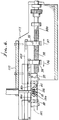
- Fig. 2 is a side view elevation showing wire displacing and processing apparatus;
- Fig. 3 is a top plan view showing the apparatus of Fig. 2;
- Fig. 4 is an end view, taken in elevation, showing wire belt displacing drive apparatus;
- Fig. 5 is an elevation showing spring urging of wire drive belts;
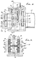
- Fig. 6 is an enlarged cross-section taken in elevation to show sheathing stripping actuator structure;
- Fig. 7 is a view like Fig. 6 but showing the blades in advanced positions;
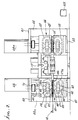
- Fig. 8 is a plan view of the Fig. 6 and Fig. 7 mechanism;
- Fig. 9 is an end view showing wire severing blades in wire severing position, as in Fig. 1b;
- Fig. 10 is an end view like Fig. 9 showing the sheathing stripping blades, in sheathing stripping position, as per Fig. 1d;
- Fig. 10a is a view showing stripping blade edge penetration into wire sheathing;
- Fig. 11 is a view like Figs. 9 and 11, but showing all blades in retracted position, as in figs. 1a and 1f; and
- Fig. 12 is an end view taken on lines 12-12 of Fig. 11.
- Referring first to Figs. 1a--1f, they show in diagramsatic form the positions of both wire severing and sheathing stripping blades, during various steps in the wire processing procedure or method. In this regard, the "wire" 10 (meant to also refer to cable) has a
metal core 11a and a tubular sheathing 11b about the core. The wire is shown extending axially longitudinally in Figs. 1a--1f, the axis being located at 12. - First cutter means is provided to include, or may be considered to include, multiple blades. See for example the two wire-
cutting blades 13a and 13b of a first set, located or carried for movement laterally toward and away from thewire axis 12. A first drive for controllably simultaneously enabling or advancing the blades toward one another, laterally oppositely (see arrows 14a and 14b in Fig. 1b), is shown at 15. That drive is also operable to retract theblades 13a and 13b away from one another. - Second and third cutter means are also provided, for sheathing stripping, and each may be considered to include multiple blades located for movement toward and away from the
axis 12. See for example the second set of twoblades blades 17a and 17b. -
Blades drive 18, laterally oppositely, toward one another (see arrows 19a and 19b in Fig. 1d), the drive also operable to retract theblades blades 17a and 17b are located or carried to be controllably displaced, simultaneously, laterally oppositely toward one another (seearrows 20a and 20b in Fig. 1d), anddrive 18 may be used for this purpose. Thus,blades blades 17a and 17b are displaced toward another, as is clear from Fig. 1d. The latter shows that theblades - Brief reference to Figs. 9-11 show the
blades blades 13a and 13b, andblades 17a and 17b. Hote edges 16a′ and 16a˝ and 16b′ and 16b˝ (ofblades blade edges 17a′ and 17a˝, and 17b′ and 17b˝ also takes place, as in Fig. 1d. - Fig. 1a shows displacement of the wire axially endwise and longitudinally, as by a conveyor means 21a to the first position as shown. Fig. 1b shows the step of severing the wire thereby to form wire forward and
rearward sections 10a and 10b, theblades 13a and 13b being advanced laterally to accomplish complete severing at locus 22, as shown. Note that wireforward section 10a has a rearward end portion 10aa; and the wire rearward section 10b has a forward end portion 10bb. - Fig. 1c shows the step of controllably separating the two
sections 10a and 10b axially endwise oppositely, as to the positions shown, in which the end portions 10aa and 10bb are spaced from the closed-together blades 13a and 13b.Guides sections 10a and 10b during the cutting and severing operation, as is clear from Figs. 1a--1f. Note thetapered entrances - Wire drives 21a and 21b are controllably operated to engage and separate the two
sections 10a and 10b, as indicated in Figs. 1a and 1c. - Fig. 1d shows a sub-step included within the step of stripping sheathing from the forward section rearward portion and from the rearward section forward portion thereby to expose wire ends at the portions. Note that
blades blades 17a and 17b are also simultaneously advanced laterally oppositely (as to the same extent if such stripping is to be equal for each wire section). Note thatblades 13a and 13b now extend in laterally overlapping condition due to operation ofdrives blades blades 13b, 16b and 17b; however, they may be separately driven so as not to extend in such relation, as shown.Blades blades 13b, 16b and 17b may also be connected together to move leftwardly as one, for extreme simplicity. - Fig. 1e shows operation of the wire drives to further endwise separate the
wire sections 10a and 10b so as to pull or strip two sheathing end portions 11b′ and 11b˝ from thewire sections 10a and 10b, thereby to expose the wirecore end portions 11a′ and 11a˝. The stripped sheathing end portions 11b′ and 11b˝, or slugs, are allowed to drop out from between the pairs ofguides - Fig. 1f shows all blades laterally retracted and the wire rearward section 10b fully advanced into position corresponding to Fig. 1a position for controlled length endwise positioning to be processed, as in Figs. 1b--1e to provide an exposed core end at its opposite end. Thus, controlled length wires (or cables), with exposed core lengths at each end of each wire, is efficiently and rapidly and controllably provided. See
master control 35 to control all the driving, as described, and to be described. - Referring now to Figs. 2-8, one form of apparatus to accomplish the above operations (Figs. 1a-1f) is shown in detail. A frame is provided, as at 40-44 and 44a, to mount two
conveyors endless belts endless belts sections 10a and 10b in Fig. 1c; and stretches 49′ and 50′ are adapted to sidewise grip the wire 10 (and specifically the wireforward section 10a) for endwise advancement and retraction. - The
belts wire section 10a as from a drive motor 52 (see Fig. 4). Theoutput shaft 53 of the motor drivesbelt 54, as via apulley 55, andbelt 54drives shafts Shaft 56 drives anothershaft 58, through gearing 59 and 60, to driveshaft 58 andupper conveyor belt 47 clockwise; whereaslower shaft 57 andlower belt 48 are driven counterclockwise in Fig. 2. This drives the wire forwardly; whereas whenmotor 52 is reversed, the wire is driven rearwardly. Additional axles or shafts for theconveyor belts - Fig. 2 shows
conveyor rotors belts Axles drive belts shafts wire 10, and themotor 52 is operating, the wire is displaced endwise. - Means is provided to move the conveyor belt stretches 47′ and 48′ toward one another to clutch the wire, and away from one another to de-clutch the wire. See for example in Figs. 3-5 the motor or drive 66 carried by a
frame part 67 to rotate avertical screw shaft 68, as viamotor output shaft 69,pulley 70,belt 71, andpulley 72 on thescrew shaft 68. The screw shaft has screw thread engagement at 33 and 34 withframe members Frame member 76 supports the ends ofshafts member extension 76a, as at 58′ and 58a′; whereasframe member 75 supports the ends ofshafts member extension 75a, as at 57′ and 57a′. Screw threading interfit at 74 is oppositely "handed" relative to threading interfit at 73, so that whenshaft 68 is rotated in one direction about its axis, theframe members shaft 68 is rotated in the opposite direction about its axis, themembers - The bearing supports at 80 and 81 for
shafts - Tension springs 90 and 91 are provided (see Fig. 5) between fixed
frame structure 92 andshoulders 76a′ on 76a to yieldably urge thestructures belt stretch 47′ downwardly; and similarly, tension springs 93 and 94 are provided between fixedframe structure 95 andshoulder 75a′ on 75 to yieldably urge thestructure belt stretch 48′ upwardly. This provides clearance "take-up" for better control of wire gripping or clamping. - The
forward conveyor unit 46 embodies conveyor belt drive and up/down movement the same as described in connection withunit 45 in Figs. 3-5. Thedrive motor 52a for driving the belt stretches 49′ and 50′ forwardly and reversely is seen in Fig. 3, as is themotor 66a to control belt clamping of the forward wire section. Mechanism between themotors forward conveyor belts motors rearward conveyor belts motors 52 and 51a are typically operated simultaneously, either to drive the wire or wire sections forwardly, as in Figs. 1a and 1f, or to drive the wire sections endwise oppositely, as in Figs. 1c and 1e. A master control to control all drives, in a pre-programmed manner, is seen at 125. - Referring to Fig. 11, the
wire severing blades 13a and 13b are fully laterally retracted, as are the wiresheathing stripping blades Blades 17a and 17b are in axial alignment withblades blade edges 13a′ and 13a˝, and blade edges 13b′ and 13b˝. Theblades wire 10 are interconnected by axially extendingcarrier rod 80; and theblades 13b, 16b and 17b at the opposite ends of the wire are interconnected by axially extendingcarrier rod 81, laterally spaced fromrod 80.Rods blades 13a and 13b (see Fig. 9 and also Fig. 1b).Rods rearward sections 10a and 10b are separated as in Fig. 1e to endwise strip the slugs 10aa and 10bb, off the wire cores, as also seen in Fig. 11. Dropping of the slug is also seen in Fig. 11, as is lowering of a wire guide lower sector B of guide 11b˝, to release the slug. The upper guide sector is shown at A. Adrive 130 is operable to lower and raise sector B.. - Means to effect the described lateral movement of the
blade carrier rods lead screw 90 is rotatable byn drive motor 91, carried byframe part 92. See connectingshaft 93. Asscrew 90 rotates in one direction about itsaxis 90a, nuts 94 and 95 on the screw threads travel axially oppositely (seearrows 96 and 97) to moverod 80 to the right androd 81 to the left, as in Figs. 9 and 10. Seeconnectors nut 94 withrod 81, andconnectors nut 95 withrod 80. A pair of parallel lead screws 90 may be utilized for these purposes, as see in Fig. 8, each driven by themotor 91, with one lead screw associated withblades blades 17a and 17b. Balanced force transmission to the two sets of blades is thereby effected. See also frame elements 110-116 supporting the structure, as indicated. Bearings appear at 117 and 118. An additional tubular wire guide is seen at 119.
Claims (25)
- A method of processing wire to cut the wire into sections and to strip sheathing from the wire to expose wire ends at opposite ends of the sections, and by operation of wire feed means and cutter means, the steps that include operating the feed means and cutter means to:a) displace the wire endwise along an axis to a first position,b) sever the wire thereby to form wire forward and rearward sections, the forward section having a rearward end portion, and the rearward section having a forward end portion, andc) stripping sheathing from the forward section rearward portion and from the rearward section forward portion thereby to expose wire ends at said portions,d) said cutter means including three blade pairs, each pair including two blades located at opposite sides of said axis, both blades of one pair being displaced toward the wire to sever the wire, and both blades of the remaining two pairs being displaced toward the wire sections to strip sheathing from said rearward and forward portions during controlled endwise displacement of said sections.
- A method as claimed in claim 1 including displacing the two sections endwise, thereby to displace wire incorporating one of the sections to said first position.
- A method as claimed in claim 1 or claim 2, wherein both blades of said one pair are displaced into overlapping relation to sever the wire, and both blades of each of the remaining two pairs are displaced to cut only into opposite sides of the sheathing to strip sheathing from said end portion of said section as said sections are displaced endwise simultaneously.
- A method as claimed in claim 1, including separating said sections axially relatively endwise after said step b) severing of the wire and prior to said step c) stripping of sheathing from said section ends.
- A method as claimed in claim 4, including further separating said sections axially relatively endwise after said blades of the remaining two pairs have been displaced toward the wire sections to cut into the sheathing, thereby to pull sheathing slugs off said wire end portions to expose said wire ends.
- A method as claimed in any preceeding claim, including guiding one or more of said displacements of the wire or wire sections endwise along said axis, at locations between blade pairs.
- A method as claimed in claim 4, wherein said separating of the sections is carried out by advancing one section and retracting the other section, relative to said one blade pair.
- A method as claimed in claim 7, wherein said further separating of the sections is carried out by further advancing the one section and further retracting the other section, relative to each one blade pair.
- A method as claimed in claim 8, including means for advancing said one section and retracting said other section, said means including forward and rearward pairs of endless conveyors, each pair of conveyors defining a wire gripping zone, and including the step of maintaining said zones in alignment with said wire sections during said further separating of the sections, axially.
- A method as claimed in claim 9, including maintaining at least one conveyor of each pair displaced relatively toward the other conveyor of said pair to clamp the wire section between said conveyors of said pairs during said further separation of the wire section, and operating said conveyor pairs in endless relation to effect said relative separation.
- Processing means for processing longitudinally axially extending wire that includes a core and protective structure extending about the core, the combination comprisinga) first blade means for relative movement laterally to sever the wire,b) other blade means spaced axially from said first blade means for relative movement laterally to penetrate said wire structure to selected depth,c) said first and other blade means being operatively interconnected to move laterally to first sever the wire and to then penetrate said structure to said selected depth.
- Processing means as claimed in claim 11, wherein said wire has longitudinal axis, said first blade means having a first cutting edge and said other blade means having another cutting edge, said cutting edges differentially spaced from said axis as said first and other blade means are simultaneously moved toward said axis prior to said severing of the wire.
- Processing means as claimed in claim 11 or claim 12, wherein said first blade means includes a first set of blades, and said other blade means includes second and third sets of blades.
- Processing means as claimed in any of claims 11 to 13, including wire guides between said first and second cutter means, and between said first and third cutter means, said guides including elements that remain in guiding position, and other elements movable out of guiding position to allow dropping of sheathing slugs stripped from wire ends.
- Processing means as claimed in claim 14, including drive means operatively connected with said other elements to effect movement thereby into and out of wire guiding position.
- Apparatus for processing wire to cut the wire into sections and to strip sheathing from the sections to expose section wire ends, the apparatus comprising:a) conveyor means for displacing the wire, including said sections, axially endwise,b) first cutter means including multiple blades located for movement toward said axis, a first drive means for controllably displacing said multiple blades toward said axis to sever the wire,c) second and third cutter means each including multiple blades located for movement toward said axis, and additional drive means for controllably displacing said multiple blades of said second and third cutter means toward said axis to cut into said sheathing, said second and third cutter means respectively located at axially opposite sides of said first cutter means and axially spaced therefrom,d) and drive means to controllably drive said conveyor means toi) position the wire to be severed by said first cutter means, thereby to produce forward and rearward wire sections,ii) relatively displace said sections axially, into positions to enable penetration of said second and third cutter means blades into said sheathing, for subsequent stripping of sheathing from a rearward portion of the forward section and from a forward portion of the rearward section, as during controlled endwise displacement of said sections by said conveyor means.
- Apparatus as claimed in claim 16, wherein said blades of said first cutter means have positions of relative overlap to sever the wire, in response to operation of said first drive means.
- Apparatus as claimed in claim 16 or claim 17, wherein said blades of said second and third cutter means have positions of penetration only into said sheathing of said section end portions to enable stripping of said sheathing end portions in response to said controllable driving of said conveyor means.
- Apparatus as claimed in any of claims 16 to 18, wherein said conveyor means includes forward and rearward pairs of endless conveyors to respectively engage and displace the wire sections, while the blades of the first cutter means are closed in overlapping relation.
- Apparatus as claimed in claim 19, including actuator means to maintain at least one conveyor of each pair displaced relatively toward the other conveyor of said pair, to clamp the wire section between the conveyors during further separation of the sections and during sheathing stripping.
- Apparatus as claimed in claim 19, wherein said conveyor comprise endless belts and including a driver to controllably advance and retract said belts endlessly.
- Apparatus as claimed in claim 20, wherein said actuator means includes a rotary screw, a drive to rotate the screw, and follower means to convert rotary motion of the screw into linear motion acting to displace the conveyor or conveyors, as aforesaid.
- Apparatus as claimed in any of claims 16 to 22, wherein said blades of the first cutter means have V-shaped edges.
- Apparatus as claimed in claim 23, wherein the blades of each of the second or third cutter means have V-shaped edges to cut into the sheathing, as aforesaid.
- Apparatus as claimed in claim 23, wherein said edges of the first cutter means blades are closer to said axis than said edges of the second and third cutter means blades, as said blades approach said axis for wire severing and sheathing stripping.
Priority Applications (1)
| Application Number | Priority Date | Filing Date | Title |
|---|---|---|---|
| EP95118745A EP0707365B1 (en) | 1990-11-09 | 1991-11-05 | Multiple blade set strip apparatus for cable and wire |
Applications Claiming Priority (2)
| Application Number | Priority Date | Filing Date | Title |
|---|---|---|---|
| US07/611,057 US5146673A (en) | 1990-11-09 | 1990-11-09 | Multiple blade set strip process for cable and wire |
| US611057 | 1990-11-09 |
Related Child Applications (2)
| Application Number | Title | Priority Date | Filing Date |
|---|---|---|---|
| EP95118745.9 Division-Into | 1991-11-05 | ||
| EP95118745A Division EP0707365B1 (en) | 1990-11-09 | 1991-11-05 | Multiple blade set strip apparatus for cable and wire |
Publications (3)
| Publication Number | Publication Date |
|---|---|
| EP0489502A2 true EP0489502A2 (en) | 1992-06-10 |
| EP0489502A3 EP0489502A3 (en) | 1993-03-31 |
| EP0489502B1 EP0489502B1 (en) | 1997-07-16 |
Family
ID=24447449
Family Applications (2)
| Application Number | Title | Priority Date | Filing Date |
|---|---|---|---|
| EP95118745A Expired - Lifetime EP0707365B1 (en) | 1990-11-09 | 1991-11-05 | Multiple blade set strip apparatus for cable and wire |
| EP91310242A Expired - Lifetime EP0489502B1 (en) | 1990-11-09 | 1991-11-05 | Multiple blade set strip apparatus for cable and wire |
Family Applications Before (1)
| Application Number | Title | Priority Date | Filing Date |
|---|---|---|---|
| EP95118745A Expired - Lifetime EP0707365B1 (en) | 1990-11-09 | 1991-11-05 | Multiple blade set strip apparatus for cable and wire |
Country Status (6)
| Country | Link |
|---|---|
| US (1) | US5146673A (en) |
| EP (2) | EP0707365B1 (en) |
| JP (1) | JPH04265607A (en) |
| AT (2) | ATE221703T1 (en) |
| CA (1) | CA2054445C (en) |
| DE (2) | DE69126849T2 (en) |
Cited By (4)
| Publication number | Priority date | Publication date | Assignee | Title |
|---|---|---|---|---|
| WO1997017751A1 (en) * | 1995-11-06 | 1997-05-15 | Schleuniger Holding Ag | Insulation stripping device |
| CN1047479C (en) * | 1993-03-24 | 1999-12-15 | 住友电装株式会社 | Apparatus for stepped-end processing of flat multi-core electric wires |
| US6910256B2 (en) * | 1995-11-06 | 2005-06-28 | Schleuniger Holding Ag | Continuous cable processing apparatus |
| CN112332318A (en) * | 2020-10-16 | 2021-02-05 | 南京子田商贸有限公司 | Environment-friendly communication cable automatic peeling device convenient to carry |
Families Citing this family (28)
| Publication number | Priority date | Publication date | Assignee | Title |
|---|---|---|---|---|
| US5664324A (en) * | 1990-11-09 | 1997-09-09 | Eubanks Engineering Company | Wire and cable cutting and stripping using adjacent blades |
| US5469763A (en) * | 1990-11-09 | 1995-11-28 | Eubanks Engineering Company | Wire and cable processing system |
| US5375485A (en) * | 1990-11-09 | 1994-12-27 | Eubanks Engineering Company | Wire and cable cutting and stripping using slidable interfitting blades with complementary configurations |
| US5293683A (en) * | 1990-11-09 | 1994-03-15 | Eubanks Engineering Company | Method for processing cable and wire |
| US5456148A (en) * | 1990-11-09 | 1995-10-10 | Eubanks Engineering Company | Wire and cable drive apparatus in wire and cable cutting and stripping system |
| US5528962A (en) * | 1990-11-09 | 1996-06-25 | Eubanks Engineering Company | Multiple blade set strip apparatus for cable and wire |
| US5517882A (en) * | 1990-11-09 | 1996-05-21 | Eubanks Engineering Company | Wire and cable cutting and stripping using slidable interfitting blades with complementary configurations |
| EP0509192A1 (en) * | 1991-04-17 | 1992-10-21 | Ttc Technology Trading Company | Device for separating and stripping electrical cables in a cable processing machine |
| US5398573A (en) * | 1992-06-24 | 1995-03-21 | Artos Engineering Company | Adjustable wire cutting and stripping apparatus |
| CH684374A5 (en) * | 1992-11-17 | 1994-08-31 | Komax Holding Ag | Kabelzuführungs- and -wechseleinrichtung for a wire processing machine. |
| JP2608235B2 (en) * | 1993-03-02 | 1997-05-07 | 日本オートマチックマシン株式会社 | Minimum forming method for strip length |
| JPH06253430A (en) * | 1993-03-02 | 1994-09-09 | Japan Automat Mach Co Ltd | Device for setting quantity of cut of covered wire |
| US5361489A (en) * | 1993-09-28 | 1994-11-08 | Bronislav Vatel | Methods of stripping insulation from wires |
| US5445051A (en) * | 1994-02-23 | 1995-08-29 | Carpenter Manufacturing Co., Inc. | Measure-cut-strip wire processing apparatus |
| US5522130A (en) * | 1994-10-13 | 1996-06-04 | Artos Engineering Company | Laser positioning system for wire cutting and stripping apparatus |
| US5689874A (en) * | 1996-09-20 | 1997-11-25 | The Whitaker Corporation | Wire cut and strip mechanism |
| US5979272A (en) * | 1997-02-10 | 1999-11-09 | Artos Engineering Company | Device for gathering, cutting and stripping insulated wire |
| JP5534727B2 (en) * | 2009-07-15 | 2014-07-02 | 三桜工業株式会社 | Metal tube exposure method for resin-coated metal tubes |
| WO2014025405A1 (en) * | 2012-08-09 | 2014-02-13 | Dwfritz Automation Inc. | Methods and apparatus for precision insertion |
| US9880213B2 (en) * | 2013-08-19 | 2018-01-30 | Oes, Inc. | Conductor monitor device and method |
| US9945892B2 (en) | 2013-08-19 | 2018-04-17 | Oes, Inc. | Wire processing machine including a conductor monitor device |
| DE102015009989A1 (en) * | 2015-07-31 | 2017-02-02 | Komax SLE GmbH & Co. KG | Cable clamping device for widening screen braids of cables |
| US12100941B2 (en) * | 2018-12-11 | 2024-09-24 | Shinmaywa Industries, Ltd. | Electrical wire processing device |
| US11654474B2 (en) * | 2019-05-02 | 2023-05-23 | Youn Ho Jung | Wire feeding unit and wire bending apparatus including the same |
| CN112713485B (en) * | 2021-01-18 | 2022-09-16 | 深圳泰华互联技术有限公司 | Quick cable connector |
| CN112864962B (en) * | 2021-02-02 | 2022-08-23 | 国网湖北省电力有限公司黄冈供电公司 | Automatic cable peeling device for electric power construction |
| CN113555824B (en) * | 2021-07-25 | 2023-03-03 | 启晗电力建设集团有限公司 | Peeler convenient for peeling high-voltage cable |
| CN116021463B (en) * | 2022-11-10 | 2025-08-05 | 国网湖北省电力有限公司孝感供电公司 | A fastening device for installing a fastening wire clamp during live power distribution work |
Family Cites Families (84)
| Publication number | Priority date | Publication date | Assignee | Title |
|---|---|---|---|---|
| US1433320A (en) * | 1922-10-24 | Charles john wersel | ||
| US1477678A (en) * | 1921-02-07 | 1923-12-18 | Miner P Wetmore | Machine for stripping insulation from electric wires |
| GB609834A (en) * | 1946-02-27 | 1948-10-07 | Percy Archibald Sporing | A machine for stripping the insulation from the ends of insulated electric conductors |
| US2523936A (en) * | 1948-08-30 | 1950-09-26 | Ideal Ind | Wire stripper |
| US2671363A (en) * | 1950-08-28 | 1954-03-09 | Gen Electric | Electrically-controlled cable stripping machine |
| US2645959A (en) * | 1950-10-06 | 1953-07-21 | Western Electric Co | Wire stripping and twisting device |
| US2811063A (en) * | 1953-09-08 | 1957-10-29 | Robert M Mcmanigal | Wire cutter and insulation stripping apparatus |
| US2722145A (en) * | 1954-04-29 | 1955-11-01 | Edward J Schulenburg | Apparatus for stripping insulation from insulated wire |
| US2765685A (en) * | 1954-06-07 | 1956-10-09 | North American Aviation Inc | Wire stripper |
| US2934982A (en) * | 1956-07-02 | 1960-05-03 | Robert M Mcmanigal | Wire cutter and insulation stripping apparatus |
| US2880635A (en) * | 1956-09-13 | 1959-04-07 | Sperry Rand Corp | Wire stripping machine |
| US3251253A (en) * | 1963-08-05 | 1966-05-17 | Edward Floyd Eubanks | Apparatus for working filamentary materials |
| US3176550A (en) * | 1963-09-12 | 1965-04-06 | Gen Electric | Wire stripping machine |
| US3222957A (en) * | 1964-06-08 | 1965-12-14 | Ingersoll Rand Co | Wire-stripper mechanism |
| US3292462A (en) * | 1965-03-17 | 1966-12-20 | Northern Electric Co | Wire stripping device |
| US3376627A (en) * | 1965-11-26 | 1968-04-09 | Amp Inc | Wire stripping apparatus |
| NL132869C (en) * | 1966-08-24 | |||
| FR1556926A (en) * | 1967-03-28 | 1969-02-07 | Lucas Industries Ltd | |
| GB1238342A (en) * | 1968-03-27 | 1971-07-07 | ||
| GB1207889A (en) * | 1968-05-03 | 1970-10-07 | Amp Inc | Insulation stripping unit for attachment to an electrical connector crimping press and a connector crimping press having insulation stripping means |
| US3612111A (en) * | 1969-09-29 | 1971-10-12 | Gen Electric | Wire cutting and stripping apparatus |
| US3653412A (en) * | 1970-06-15 | 1972-04-04 | Artos Engineering Co | Conveyor transfer unit |
| US3701301A (en) * | 1971-03-17 | 1972-10-31 | Artos Engineering Co | Wire length measuring and cutting apparatus |
| US3769681A (en) * | 1971-03-23 | 1973-11-06 | F Eubanks | Apparatus for attaching terminals to electric conductors |
| JPS5433103Y2 (en) * | 1972-11-01 | 1979-10-12 | ||
| JPS5539432B2 (en) * | 1972-11-01 | 1980-10-11 | ||
| US3857306A (en) * | 1973-06-15 | 1974-12-31 | Artos Engineering Co | Cable cutting and stripping machine |
| US3869781A (en) * | 1974-02-25 | 1975-03-11 | Eubanks Eng Co | Apparatus for attaching terminals to electric conductors |
| US3872584A (en) * | 1974-02-27 | 1975-03-25 | Amp Inc | Method and apparatus for processing a plurality of wire leads |
| US3881374A (en) * | 1974-05-24 | 1975-05-06 | Artos Engineering Co | Rotary wire stripper |
| JPS5240667B2 (en) * | 1974-07-25 | 1977-10-13 | ||
| US3927590A (en) * | 1974-10-10 | 1975-12-23 | Artos Engineering Co | Apparatus for producing electrical conductors of measured length |
| JPS5149487A (en) * | 1974-10-25 | 1976-04-28 | Shin Meiwa Ind Co Ltd | Hifukusensetsudan hifukuhagitori oyobi shinsenyoriki |
| US3918330A (en) * | 1974-11-18 | 1975-11-11 | Artos Engineering Co | Insulated wire cutting and stripping apparatus |
| JPS5169178A (en) * | 1974-12-13 | 1976-06-15 | Hitachi Ltd | Hifukudensenno sokuchokatsuto sutoritsupuhoho |
| US3921472A (en) * | 1975-03-12 | 1975-11-25 | Artos Engineering Co | Rotary wire stripper |
| GB1564199A (en) * | 1975-11-11 | 1980-04-02 | Weidmueller Kg C | Tools for stripping sheating from cables and the like |
| CH609176A5 (en) * | 1976-04-26 | 1979-02-15 | Loepfe K Automation Ag | |
| US4091695A (en) * | 1977-02-28 | 1978-05-30 | Molex Incorporated | Wire preparation machine with variable insulation stripping mechanism |
| DE2857307C2 (en) * | 1977-03-25 | 1982-05-19 | Shin Meiwa Industry Co.,Ltd., Nishinomiya, Hyogo | Cutting and stripping device |
| AU524248B2 (en) * | 1978-02-01 | 1982-09-09 | Utilux Pty Limited | Electric cable processing |
| US4156961A (en) * | 1978-05-17 | 1979-06-05 | Shin Meiwa Industry Co., Ltd. | Wire collecting apparatus for use with wire cutting and insulation stripping machine |
| US4166315A (en) * | 1978-06-05 | 1979-09-04 | Artos Engineering Company | Wire gathering mechanism for wire lead production apparatus |
| US4165768A (en) * | 1978-06-05 | 1979-08-28 | Artos Engineering Company | Wire straightening mechanism for wire lead production apparatus |
| US4164808A (en) * | 1978-06-05 | 1979-08-21 | Artos Engineering Company | Apparatus for producing sets of accurately and identically sized wire leads |
| US4175316A (en) * | 1978-06-05 | 1979-11-27 | Artos Engineering Company | Wire lead clamping mechanism for wire lead production apparatus |
| GB2030898B (en) * | 1978-07-04 | 1982-06-16 | Burndy Corp | Electrical lead transfer unit |
| US4194281A (en) * | 1978-09-25 | 1980-03-25 | Artos Engineering Company | Apparatus and method for stripping wire leads |
| JPS55105910A (en) * | 1979-02-08 | 1980-08-14 | Shin Meiwa Ind Co Ltd | Device for feeding long wire for wire cutter or like |
| CH643406A5 (en) * | 1979-02-19 | 1984-05-30 | Klaussner Hans Jurgen | Device for stripping the insulation off electrical conductors |
| US4244101A (en) * | 1979-02-26 | 1981-01-13 | Eubanks Engineering Co. | Apparatus for attaching terminals to electric conductors |
| US4261230A (en) * | 1979-06-25 | 1981-04-14 | Black & Decker Inc. | Wire stripping machine and stripping element therefor |
| US4350061A (en) * | 1979-11-01 | 1982-09-21 | Ideal Industries, Inc. | Wire stripping mechanism |
| US4327609A (en) * | 1979-11-19 | 1982-05-04 | Bunker Ramo Corporation | Apparatus for removing the insulation from electrical wires |
| US4364289A (en) * | 1980-03-20 | 1982-12-21 | Belden Corporation | Wire stripper apparatus |
| CA1176436A (en) * | 1980-10-07 | 1984-10-23 | Vladimiro Teagno | Method and apparatus for making modular electrical harnesses including wire holding head |
| US4370786A (en) * | 1981-02-20 | 1983-02-01 | Artos Engineering Company | Wire lead forming machine |
| FR2513478A1 (en) * | 1981-09-24 | 1983-03-25 | Automatismes Tech Avancees | METHOD AND MACHINE FOR CUTTING INTO AN ELECTRICAL WIRE TRONCONS OF LENGTHS DETERMINED AND FOR TREATING AND EQUIPPING THE TWO END OF THESE TRONCONS |
| US4446615A (en) * | 1982-03-16 | 1984-05-08 | Eubanks Engineering Company | Apparatus for attaching terminals to the ends of electric conductors |
| US4502586A (en) * | 1982-03-31 | 1985-03-05 | Artos Engineering Company | Belt type conveyor for conveying wire segments |
| US4521946A (en) * | 1982-03-31 | 1985-06-11 | Artos Engineering Company | Cutter and belt type conveyor for wire segments |
| FR2525403A1 (en) * | 1982-04-16 | 1983-10-21 | Automatismes Tech Avancees | Automatic conveyor mechanism for cutting and stripping wire sections - uses system of toothed belts to increase accuracy of wire length drawn and has articulated jaw mechanism to strip insulation |
| US4597179A (en) * | 1983-04-29 | 1986-07-01 | Sidney Goforth | Component lead processor trimming and forming tool |
| US4493233A (en) * | 1983-06-22 | 1985-01-15 | Artos Engineering Company | Apparatus for cutting and conveying segments of wire or cable |
| DE3325719A1 (en) * | 1983-07-16 | 1985-01-31 | Grote & Hartmann Gmbh & Co Kg, 5600 Wuppertal | METHOD AND DEVICE FOR PRODUCING CABLES FITTED WITH ELECTRICAL CONNECTORS |
| JPS6039787A (en) * | 1983-08-12 | 1985-03-01 | 住友電気工業株式会社 | Automatic molding machine of terminal press-bonded wire |
| US4543717A (en) * | 1983-12-16 | 1985-10-01 | Tektronix, Inc. | Cable stripper |
| JPS60204206A (en) * | 1984-03-27 | 1985-10-15 | 株式会社小寺電子製作所 | Automatic wire cutting and exfoliating machine |
| US4638558A (en) * | 1984-05-31 | 1987-01-27 | Mts Vektronics Corporation | Wire processing method and apparatus |
| US4838129A (en) * | 1984-09-21 | 1989-06-13 | Eubanks Engineering Co. | Wire insulation stripping apparatus |
| US4601093A (en) * | 1984-09-21 | 1986-07-22 | Eubanks Engineering Co. | Wire insulation stripping apparatus |
| JPS61196706A (en) * | 1985-02-22 | 1986-08-30 | イリ シユテパン | Insulator stripping apparatus |
| US4584912A (en) * | 1985-05-06 | 1986-04-29 | Artos Engineering Company | Wire feeding, cutting and stripping apparatus having clutch-operated feed and cam-operated cutter/stripper |
| JPS61273114A (en) * | 1985-05-25 | 1986-12-03 | 株式会社 小寺電子製作所 | Cutting in and peeling of cover for automatic wire cutter/peeler |
| US4802512A (en) * | 1986-02-25 | 1989-02-07 | Kabushiki, Kaisha, Kodera, Denshi, Seisakusho | Automatic wire decorticating and cutting method and apparatus |
| US4713880A (en) * | 1986-04-08 | 1987-12-22 | Artos Engineering Company | Lead making machine |
| JP2628631B2 (en) * | 1986-04-09 | 1997-07-09 | アポロ精工株式会社 | Wire stripper device and automatic wiring device using the same |
| US4833778A (en) * | 1986-12-22 | 1989-05-30 | Eubanks Engineering Co. | Wire processing apparatus and method |
| JPS63181610A (en) * | 1987-01-20 | 1988-07-26 | 株式会社小寺電子製作所 | Automatic wire cutting/stripping |
| JP2870761B2 (en) * | 1988-07-04 | 1999-03-17 | 日本エー・エム・ピー株式会社 | Electric harness manufacturing equipment |
| US4869135A (en) * | 1988-07-18 | 1989-09-26 | Eubanks Engineering Co. | Apparatus for step stripping wire means |
| JPH0817107B2 (en) * | 1989-04-19 | 1996-02-21 | 日本圧着端子製造株式会社 | Method and device for cutting shielded ribbon cable in automatic crimping machine |
| JPH0349815A (en) * | 1989-07-17 | 1991-03-04 | K D S:Kk | Automatic wire cutting and peeling device |
| EP0423443B1 (en) * | 1989-10-18 | 1994-09-28 | Ttc Technology Trading Company | Process and device for carrying-out the process to feed a cable into a cable manufacturing automaton |
-
1990
- 1990-11-09 US US07/611,057 patent/US5146673A/en not_active Expired - Lifetime
-
1991
- 1991-10-29 CA CA002054445A patent/CA2054445C/en not_active Expired - Fee Related
- 1991-11-05 AT AT95118745T patent/ATE221703T1/en not_active IP Right Cessation
- 1991-11-05 DE DE69126849T patent/DE69126849T2/en not_active Expired - Fee Related
- 1991-11-05 AT AT91310242T patent/ATE155620T1/en not_active IP Right Cessation
- 1991-11-05 EP EP95118745A patent/EP0707365B1/en not_active Expired - Lifetime
- 1991-11-05 DE DE69133081T patent/DE69133081T2/en not_active Expired - Fee Related
- 1991-11-05 EP EP91310242A patent/EP0489502B1/en not_active Expired - Lifetime
- 1991-11-11 JP JP3294459A patent/JPH04265607A/en active Pending
Cited By (6)
| Publication number | Priority date | Publication date | Assignee | Title |
|---|---|---|---|---|
| CN1047479C (en) * | 1993-03-24 | 1999-12-15 | 住友电装株式会社 | Apparatus for stepped-end processing of flat multi-core electric wires |
| WO1997017751A1 (en) * | 1995-11-06 | 1997-05-15 | Schleuniger Holding Ag | Insulation stripping device |
| EP1271729A3 (en) * | 1995-11-06 | 2003-08-06 | Schleuniger Holding AG | Insulation stripping device |
| US6910256B2 (en) * | 1995-11-06 | 2005-06-28 | Schleuniger Holding Ag | Continuous cable processing apparatus |
| US8234772B2 (en) | 1995-11-06 | 2012-08-07 | Schleuniger Holding Ag | Continuous cable processing apparatus |
| CN112332318A (en) * | 2020-10-16 | 2021-02-05 | 南京子田商贸有限公司 | Environment-friendly communication cable automatic peeling device convenient to carry |
Also Published As
| Publication number | Publication date |
|---|---|
| EP0707365A1 (en) | 1996-04-17 |
| DE69133081D1 (en) | 2002-09-05 |
| EP0489502B1 (en) | 1997-07-16 |
| CA2054445A1 (en) | 1992-05-10 |
| DE69126849D1 (en) | 1997-08-21 |
| DE69133081T2 (en) | 2003-01-16 |
| EP0489502A3 (en) | 1993-03-31 |
| DE69126849T2 (en) | 1998-01-08 |
| EP0707365B1 (en) | 2002-07-31 |
| ATE221703T1 (en) | 2002-08-15 |
| ATE155620T1 (en) | 1997-08-15 |
| US5146673A (en) | 1992-09-15 |
| JPH04265607A (en) | 1992-09-21 |
| CA2054445C (en) | 1994-12-13 |
Similar Documents
| Publication | Publication Date | Title |
|---|---|---|
| EP0489502B1 (en) | Multiple blade set strip apparatus for cable and wire | |
| US5199328A (en) | Multiple blade set strip apparatus for cable and wire | |
| US5402693A (en) | Multiple blade set strip apparatus for cable and wire | |
| US5630341A (en) | Method for processing cable and wire | |
| US6854177B2 (en) | Apparatus for processing wire | |
| US5539967A (en) | Multiple blade set strip apparatus for cable and wire | |
| US5653016A (en) | Wire and cable drive apparatus in wire and cable cutting and stripping system | |
| EP1079478A1 (en) | Method and device for cutting and/or removing insulation from insulated cables | |
| US5515602A (en) | Multiple blade set strip apparatus for cable and wire | |
| US5297457A (en) | Multiple blade set strip apparatus for cable and wire | |
| US5285569A (en) | Method of processing wire using multiple blade set | |
| US5265502A (en) | Multiple blade set strip apparatus for cable and wire | |
| US5469763A (en) | Wire and cable processing system | |
| US5528962A (en) | Multiple blade set strip apparatus for cable and wire | |
| US5375485A (en) | Wire and cable cutting and stripping using slidable interfitting blades with complementary configurations | |
| US5517882A (en) | Wire and cable cutting and stripping using slidable interfitting blades with complementary configurations | |
| CN121749008A (en) | An electrical engineering and automation wiring device |
Legal Events
| Date | Code | Title | Description |
|---|---|---|---|
| PUAI | Public reference made under article 153(3) epc to a published international application that has entered the european phase |
Free format text: ORIGINAL CODE: 0009012 |
|
| AK | Designated contracting states |
Kind code of ref document: A2 Designated state(s): AT BE CH DE DK ES FR GB GR IT LI LU NL SE |
|
| PUAL | Search report despatched |
Free format text: ORIGINAL CODE: 0009013 |
|
| AK | Designated contracting states |
Kind code of ref document: A3 Designated state(s): AT BE CH DE DK ES FR GB GR IT LI LU NL SE |
|
| 17P | Request for examination filed |
Effective date: 19930913 |
|
| 17Q | First examination report despatched |
Effective date: 19940629 |
|
| GRAH | Despatch of communication of intention to grant a patent |
Free format text: ORIGINAL CODE: EPIDOS IGRA |
|
| GRAH | Despatch of communication of intention to grant a patent |
Free format text: ORIGINAL CODE: EPIDOS IGRA |
|
| GRAH | Despatch of communication of intention to grant a patent |
Free format text: ORIGINAL CODE: EPIDOS IGRA |
|
| GRAH | Despatch of communication of intention to grant a patent |
Free format text: ORIGINAL CODE: EPIDOS IGRA |
|
| GRAA | (expected) grant |
Free format text: ORIGINAL CODE: 0009210 |
|
| AK | Designated contracting states |
Kind code of ref document: B1 Designated state(s): AT BE CH DE DK ES FR GB GR IT LI LU NL SE |
|
| DX | Miscellaneous (deleted) | ||
| PG25 | Lapsed in a contracting state [announced via postgrant information from national office to epo] |
Ref country code: AT Effective date: 19970716 Ref country code: BE Effective date: 19970716 Ref country code: ES Free format text: THE PATENT HAS BEEN ANNULLED BY A DECISION OF A NATIONAL AUTHORITY Effective date: 19970716 Ref country code: GR Free format text: LAPSE BECAUSE OF FAILURE TO SUBMIT A TRANSLATION OF THE DESCRIPTION OR TO PAY THE FEE WITHIN THE PRESCRIBED TIME-LIMIT Effective date: 19970716 Ref country code: DK Effective date: 19970716 Ref country code: NL Free format text: LAPSE BECAUSE OF FAILURE TO SUBMIT A TRANSLATION OF THE DESCRIPTION OR TO PAY THE FEE WITHIN THE PRESCRIBED TIME-LIMIT Effective date: 19970716 |
|
| REF | Corresponds to: |
Ref document number: 155620 Country of ref document: AT Date of ref document: 19970815 Kind code of ref document: T |
|
| REG | Reference to a national code |
Ref country code: CH Ref legal event code: NV Representative=s name: PATENTANWAELTE SCHAAD, BALASS, MENZL & PARTNER AG Ref country code: CH Ref legal event code: EP |
|
| REF | Corresponds to: |
Ref document number: 69126849 Country of ref document: DE Date of ref document: 19970821 |
|
| ET | Fr: translation filed | ||
| PG25 | Lapsed in a contracting state [announced via postgrant information from national office to epo] |
Ref country code: SE Effective date: 19971016 |
|
| PG25 | Lapsed in a contracting state [announced via postgrant information from national office to epo] |
Ref country code: LU Free format text: LAPSE BECAUSE OF NON-PAYMENT OF DUE FEES Effective date: 19971105 |
|
| NLV1 | Nl: lapsed or annulled due to failure to fulfill the requirements of art. 29p and 29m of the patents act | ||
| PLBE | No opposition filed within time limit |
Free format text: ORIGINAL CODE: 0009261 |
|
| STAA | Information on the status of an ep patent application or granted ep patent |
Free format text: STATUS: NO OPPOSITION FILED WITHIN TIME LIMIT |
|
| 26N | No opposition filed | ||
| REG | Reference to a national code |
Ref country code: GB Ref legal event code: IF02 |
|
| PGFP | Annual fee paid to national office [announced via postgrant information from national office to epo] |
Ref country code: CH Payment date: 20081125 Year of fee payment: 18 |
|
| PGFP | Annual fee paid to national office [announced via postgrant information from national office to epo] |
Ref country code: IT Payment date: 20081127 Year of fee payment: 18 |
|
| PGFP | Annual fee paid to national office [announced via postgrant information from national office to epo] |
Ref country code: FR Payment date: 20081117 Year of fee payment: 18 |
|
| PGFP | Annual fee paid to national office [announced via postgrant information from national office to epo] |
Ref country code: DE Payment date: 20081223 Year of fee payment: 18 |
|
| PGFP | Annual fee paid to national office [announced via postgrant information from national office to epo] |
Ref country code: GB Payment date: 20081128 Year of fee payment: 18 |
|
| REG | Reference to a national code |
Ref country code: CH Ref legal event code: PL |
|
| GBPC | Gb: european patent ceased through non-payment of renewal fee |
Effective date: 20091105 |
|
| REG | Reference to a national code |
Ref country code: FR Ref legal event code: ST Effective date: 20100730 |
|
| PG25 | Lapsed in a contracting state [announced via postgrant information from national office to epo] |
Ref country code: LI Free format text: LAPSE BECAUSE OF NON-PAYMENT OF DUE FEES Effective date: 20091130 Ref country code: FR Free format text: LAPSE BECAUSE OF NON-PAYMENT OF DUE FEES Effective date: 20091130 Ref country code: CH Free format text: LAPSE BECAUSE OF NON-PAYMENT OF DUE FEES Effective date: 20091130 |
|
| PG25 | Lapsed in a contracting state [announced via postgrant information from national office to epo] |
Ref country code: DE Free format text: LAPSE BECAUSE OF NON-PAYMENT OF DUE FEES Effective date: 20100601 |
|
| PG25 | Lapsed in a contracting state [announced via postgrant information from national office to epo] |
Ref country code: GB Free format text: LAPSE BECAUSE OF NON-PAYMENT OF DUE FEES Effective date: 20091105 |
|
| PG25 | Lapsed in a contracting state [announced via postgrant information from national office to epo] |
Ref country code: IT Free format text: LAPSE BECAUSE OF NON-PAYMENT OF DUE FEES Effective date: 20091105 |