EP0489142B1 - Unterseepumpenanlage - Google Patents
Unterseepumpenanlage Download PDFInfo
- Publication number
- EP0489142B1 EP0489142B1 EP91912239A EP91912239A EP0489142B1 EP 0489142 B1 EP0489142 B1 EP 0489142B1 EP 91912239 A EP91912239 A EP 91912239A EP 91912239 A EP91912239 A EP 91912239A EP 0489142 B1 EP0489142 B1 EP 0489142B1
- Authority
- EP
- European Patent Office
- Prior art keywords
- mas tree
- pump unit
- hanger
- tree
- conductor means
- Prior art date
- Legal status (The legal status is an assumption and is not a legal conclusion. Google has not performed a legal analysis and makes no representation as to the accuracy of the status listed.)
- Expired - Lifetime
Links
Images
Classifications
-
- E—FIXED CONSTRUCTIONS
- E21—EARTH OR ROCK DRILLING; MINING
- E21B—EARTH OR ROCK DRILLING; OBTAINING OIL, GAS, WATER, SOLUBLE OR MELTABLE MATERIALS OR A SLURRY OF MINERALS FROM WELLS
- E21B33/00—Sealing or packing boreholes or wells
- E21B33/02—Surface sealing or packing
- E21B33/03—Well heads; Setting-up thereof
- E21B33/068—Well heads; Setting-up thereof having provision for introducing objects or fluids into, or removing objects from, wells
- E21B33/076—Well heads; Setting-up thereof having provision for introducing objects or fluids into, or removing objects from, wells specially adapted for underwater installations
-
- E—FIXED CONSTRUCTIONS
- E21—EARTH OR ROCK DRILLING; MINING
- E21B—EARTH OR ROCK DRILLING; OBTAINING OIL, GAS, WATER, SOLUBLE OR MELTABLE MATERIALS OR A SLURRY OF MINERALS FROM WELLS
- E21B33/00—Sealing or packing boreholes or wells
- E21B33/02—Surface sealing or packing
- E21B33/03—Well heads; Setting-up thereof
- E21B33/035—Well heads; Setting-up thereof specially adapted for underwater installations
- E21B33/0353—Horizontal or spool trees, i.e. without production valves in the vertical main bore
-
- F—MECHANICAL ENGINEERING; LIGHTING; HEATING; WEAPONS; BLASTING
- F04—POSITIVE - DISPLACEMENT MACHINES FOR LIQUIDS; PUMPS FOR LIQUIDS OR ELASTIC FLUIDS
- F04D—NON-POSITIVE-DISPLACEMENT PUMPS
- F04D13/00—Pumping installations or systems
- F04D13/02—Units comprising pumps and their driving means
- F04D13/06—Units comprising pumps and their driving means the pump being electrically driven
- F04D13/08—Units comprising pumps and their driving means the pump being electrically driven for submerged use
- F04D13/10—Units comprising pumps and their driving means the pump being electrically driven for submerged use adapted for use in mining bore holes
-
- F—MECHANICAL ENGINEERING; LIGHTING; HEATING; WEAPONS; BLASTING
- F04—POSITIVE - DISPLACEMENT MACHINES FOR LIQUIDS; PUMPS FOR LIQUIDS OR ELASTIC FLUIDS
- F04D—NON-POSITIVE-DISPLACEMENT PUMPS
- F04D29/00—Details, component parts, or accessories
- F04D29/60—Mounting; Assembling; Disassembling
- F04D29/605—Mounting; Assembling; Disassembling specially adapted for liquid pumps
- F04D29/606—Mounting in cavities
Definitions
- the invention relates to a subsea fluid extraction system.
- submersible pumps In subsea or undersea fluid extraction systems, operational efficiency can be improved by the use of submersible pumps, in particular where production is for wells remote from a mother platform or fluid processing facility, so that the well effluent requires to be transported over substantial distances.
- Submersible pumps could also be used in multi-phase marginal field wells where the fluid is monophasic downhole.
- electrically powered submersible pumps tend to be very prone to breakdown and are generally unreliable. Average operational times before failure may be only a few months. More often than not, failure is due to a damaged external power cable. Such pumps are accordingly unattractive economically because of the cost of frequent well shut-downs.
- the present invention is concerned with the provision of a fluid extraction system of the kind described in which the above-mentioned disadvantage is avoided.
- the invention thus provides a subsea fluid extraction system of the kind described in which the elongate conductor means comprises a rigid tubular or pipe-like electrical conductor assembly comprising a plurality of concentric tubular conductors adapted to suspend and support the pump unit and provide at least one fluid passage communicating to the pump unit and adapted to incorporate fluid passages for circulation of barrier fluid through the pump unit (23).
- the X-mas tree of the invention thus can comprise a hollow stem having at its upper end, which is normally closed by a protective cap, a hanger for the conductor assembly or power tubing.
- Production tubing extends downhole from the wellhead structure and the conductor assembly is suspended from the hanger so as to extend within it to define a space between the tubing and the assembly for the well effluent.
- Valving for the pumped effluent is carried by an X-mas tree block below the hanger.
- the mounting of the conductor assembly or power tubing in the X-mas tree permits the pump unit to be run and retrieved on the rigid power tubing in a manner similar to a wire line operation, that is, the power tubing or assembly is run through the X-mas tree. In appropriate circumstances, the pump system can be run and and pulled without killing the well.
- the electrical conductor assembly can be suitably configured in accordance with the disclosures of EP 0 063 444 (FD1/2), and EP 0 089 121 9FD3), with conductor tubing surrounded by outer piping to constitute power tubing in which a barrier fluid can be circulated between the wellhead and downhole equipment.
- the conductor assembly can thus conveniently comprise a plurality of concentric tubular conductors, typically three for a 3-phase power supply, separated by solid insulation. External insulation for the tubular conductors can be effected similarly and/or by dielectric fluid, typically an insulating oil which may be circulated within and outside the conductor tubing by means of spaced outer tubing within which the conductor tubing is received.
- the system of the invention thus includes no electric cabling susceptible to damage during running and pulling operations so the mean time before failure is expected to be substantially increased as compared with prior art systems, perhaps to two or three years, with evident economic advantage. Moreover, cable handling and feed-through equipment is rendered unnecessary.
- a barrier fluid circulated by means of the power tubing can be employed for cooling lubrication and internal overpressure protection of downhole equipment.
- the barrier fluid can be used to operate a deep set downhole safety valve (DHSV). No separate control line to the DHSV is then required, so a vulnerable item can be eliminated.
- DHSV deep set downhole safety valve
- Electrical power supply connection and also fluid connection if required can be made to the hanger and thus to the power tubing by means of a female connector carried at a position to one side of the X-mas tree and adapted for a wet mateable connection with an upright connector element, which can be mounted on a transformer unit on the wellhead structure.
- An umbilical conveys the necessary supplies to the transformer unit.
- horizontal stab-in connections can be provided for between the transformer unit and the X-mas tree and/or between the umbilical and the transformer unit.
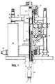
- the subsea wellhead equipment illustrated is mounted on a permanent guide base 1.
- the base supports production tubing 2 extending downhole through a central aperture in the guide base and comprising an upper tubing end portion above the guide base to which is secured a wellhead connector 4.
- a casing hanger 5 Internally of the tubing 2 is a casing hanger 5 for 24.45 cm (9 5/8 inches) casing 6.
- Above the wellhead connector is located an X-mas tree 10 supporting within it a hanger 11 for 17.78 cm (7 inches) tubing 12 extending downhole concentrically within the casing 6.
- Valving for the well effluent is located above the connector 4.
- the annular space between the casing 6 and the tubing 12 is communicated outwardly of an X-mas tree block 14 through a master valve 15 and a wing valve 16.
- the space within the tubing 12 is similarly communicated outwardly through a master valve 19 and a wing valve 20 in the block 14.
- the upper part of the X-mas tree 10 has releasably secured within it a pump hanger 21 from which there extends downhole conductor or power tubing 22 carrying at its lower end a pump unit 23, shown schematically comprising suitable pump or impeller means driven by an electric motor.
- a protection cap 24 closes off the upper end of the X-mas tree 10.
- the pump hanger 21 serves additionally as a mechanical seal barrier in the X-mas tree.
- An additional plug with seals can be installed between the pump hanger 21 and the protection cap 24 to provide an extra seal barrier against the well if deemed necessary.
- the power tubing 22 comprises an assembly of three concentric electrical conductor tubes with insulating sleeves between them, surrounded by outer tubing with spacing from the conductor assembly. The interior of the conductor assembly and the space between it and the outer tubing provide flow and return paths for barrier fluid, typically a dielectric oil.
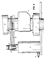
- Fluid and electrical power supply connections from an umbilical 30 are made to the hanger 21 and thence to the power tubing 22 by way of a transformer unit 32 mounted on the guide base 1 adjacent the X-mas tree 10.
- a connector element 34 extends upright so as to make a wet mateable connection with a passive vertical female connector element 35 carried at the free end of an arm 36 projecting laterally from the X-mas tree.
- the connector elements 34 and 35 provide concentric electrical and fluid communications and the inner end of the arm 36 at 37 constitutes, in effect, a similar but permanent connection with electrical conductors and fluid passages 39 within the pump hanger 21. This arrangement permits vertical installation of the hanger 21 and the X-mas tree 10 with automatic establishment of the electrical and barrier fluid connections upon landing.
- a horizontal stab multi-connector with hydraulic stroking, could be employed at the X-mas tree interface, in replacement of the wet mateable connector above the transformer unit 31. This permits independent installation and retrieval of the transformer unit and the X-mas tree, in any desired sequence.
- a horizontal stab multi-connector could be employed at the umbilical head, with a permanent or "hard-pipe” connection between the transformer unit and the X-mas tree. This permits the umbilical to be installed and retrieved independently of the module comprising the X-mas tree and the transformer unit, thereby extending the operational water depth of the system and limiting the risk of damage to the umbilical.
- the power tubing 22 is conveniently constructed of sections of 12-15 metres length with conventional pindown and box-up connections for the outer tubing sections.
- the electrical conductor tubing is in corresponding lengths and is suspended within each tubular section by suitable spacing elements.
- Each length of the conductor tubing is configured at each end to ensure electrical continuity for the respective conductor tubes throughout its length from the wellhead to the pump unit.
- the pump unit 23 connected directly to the power tubing 22 so as to be carried thereby, can be run down the production tubing through the X-mas tree 10 during installation, to be landed at a predetermined setting depth on a landing shoulder with a seal nipple which is integrated into the downhole completion assembly. Sealing to the X-mas tree 10 is effected by the seal arrangements described above. Conversely, retrieval of the pump unit 23 can be effected by lifting the production tubing to carry the pump unit up through the X-mas tree.
Landscapes
- Engineering & Computer Science (AREA)
- Mining & Mineral Resources (AREA)
- Life Sciences & Earth Sciences (AREA)
- Geology (AREA)
- General Engineering & Computer Science (AREA)
- Mechanical Engineering (AREA)
- Geochemistry & Mineralogy (AREA)
- General Life Sciences & Earth Sciences (AREA)
- Physics & Mathematics (AREA)
- Fluid Mechanics (AREA)
- Environmental & Geological Engineering (AREA)
- Structures Of Non-Positive Displacement Pumps (AREA)
- Jet Pumps And Other Pumps (AREA)
- Pipeline Systems (AREA)
- Connector Housings Or Holding Contact Members (AREA)
- Laying Of Electric Cables Or Lines Outside (AREA)
- Sampling And Sample Adjustment (AREA)
- Manufacture Of Tobacco Products (AREA)
- Reciprocating Pumps (AREA)
Claims (6)
- Untersee-Fluidextraktionssystem mit Bohrlochausrüstung, wobei die Bohrlochausrüstung folgendes umfaßt: einen Steigrohrkopf (10) mit einer durchgehenden Bohrung darin, eine elektrisch angetriebene Pumpeneinheit (23), die mit einem länglichen Leiter (22) an der Bohrlochausrüstung aufgehängt ist, wobei die Pumpeneinheit und der Leiter so angeordnet sind, daß sie durch die Bohrung des Steigrohrkopfes abgelassen und gefischt werden, ein Aufhängemittel (21) in dem Steigrohrkopf, in den der Leiter eingreift, um die Pumpeneinheit an dem Steigrohrkopf aufzuhängen, und ein elektrisches Anschlußmittel (37) in dem Aufhängemittel für eine elektrische Kommunikation des Leiters außerhalb des Steigrohrkopfes, dadurch gekennzeichnet, daß der längliche Leiter (22) eine starre röhrenförmige oder rohrähnliche Stromleiterbaugruppe aufweist, umfassend eine Mehrzahl von konzentrischen röhrenförmigen Leitern, an denen die Pumpeneinheit aufgehängt ist und die diese tragen und die wenigstens einen Fluidkanal in Verbindung mit der Pumpeneinheit (23) bereitstellen, und die Fluidkanäle für die Zirkulation von Sperrfluid durch die Pumpeneinheit (23) beinhalten.
- System nach Anspruch 1, bei dem die Pumpenaufhängung (21) so angeordnet ist, daß sie mit dem Steigrohrkopf (10) zusammenwirkt, um eine mechanische Dichtungsbarriere dazwischen zu bilden.
- System nach einem der vorherigen Ansprüche, bei dem das elektrische Anschlußmittel (37) die Verbindung zwischen dem Leiter (22) und einer elektrischen Stromquelle (32) außerhalb des Steigrohrkopfes (10) herstellt.
- System nach Anspruch 3, bei dem das elektrische Anschlußmittel (37) einen Arm (36) aufweist, der lateral vom Steigrohrkopf (10) zu einer lösbaren Anschlußvorrichtung für den Anschluß an eine elektrische Stromquelle (32) verläuft.
- System nach Anspruch 4, bei dem die lösbare Anschlußvorrichtung ein vertikales Aufnahmeanschlußelement (35) aufweist, das so angeordnet ist, daß es zusammen mit einem festen Anschlußelement (34) der Bohrlochausrüstung nach dem Landen der Aufhängung (21) und des Steigrohrkopfes (10) auf der Ausrüstung einen ineinandersteckbaren Anschluß bildet.
- System nach einem der vorhergehenden Ansprüche, bei dem an dem Steigrohrkopf (10) Ventile (15, 16, 19, 20) für Bohrlochabwasser montiert sind, das zwischen dem Leiter (22) und dem Produktionsrohr (2) extrahiert wird, in dem der Leiter verläuft.
Applications Claiming Priority (3)
| Application Number | Priority Date | Filing Date | Title |
|---|---|---|---|
| GB909014237A GB9014237D0 (en) | 1990-06-26 | 1990-06-26 | Subsea pump system |
| GB9014237 | 1990-06-26 | ||
| PCT/GB1991/001031 WO1992000438A1 (en) | 1990-06-26 | 1991-06-26 | Subsea pump system |
Publications (2)
| Publication Number | Publication Date |
|---|---|
| EP0489142A1 EP0489142A1 (de) | 1992-06-10 |
| EP0489142B1 true EP0489142B1 (de) | 1997-01-15 |
Family
ID=10678246
Family Applications (1)
| Application Number | Title | Priority Date | Filing Date |
|---|---|---|---|
| EP91912239A Expired - Lifetime EP0489142B1 (de) | 1990-06-26 | 1991-06-26 | Unterseepumpenanlage |
Country Status (11)
| Country | Link |
|---|---|
| US (1) | US5280766A (de) |
| EP (1) | EP0489142B1 (de) |
| AT (1) | ATE147832T1 (de) |
| BR (1) | BR9105802A (de) |
| CA (1) | CA2065324C (de) |
| DE (1) | DE69124212T2 (de) |
| DK (1) | DK0489142T3 (de) |
| ES (1) | ES2095941T3 (de) |
| GB (1) | GB9014237D0 (de) |
| NO (1) | NO304848B1 (de) |
| WO (1) | WO1992000438A1 (de) |
Families Citing this family (48)
| Publication number | Priority date | Publication date | Assignee | Title |
|---|---|---|---|---|
| DE69231713T3 (de) | 1992-06-01 | 2009-10-29 | Cooper Cameron Corp., Houston | Bohrlochkopf |
| DE69319239T2 (de) | 1993-08-04 | 1998-10-22 | Cooper Cameron Corp | Elektrische Verbindung |
| GB9604803D0 (en) * | 1996-03-07 | 1996-05-08 | Expro North Sea Ltd | High pressure tree cap |
| AU9791898A (en) * | 1997-10-07 | 1999-04-27 | Fmc Corporation | Slimbore subsea completion system and method |
| US6923273B2 (en) | 1997-10-27 | 2005-08-02 | Halliburton Energy Services, Inc. | Well system |
| US6293345B1 (en) * | 1998-03-26 | 2001-09-25 | Dril-Quip, Inc. | Apparatus for subsea wells including valve passageway in the wall of the wellhead housing for access to the annulus |
| GB2365890C (en) * | 2000-08-21 | 2006-02-07 | Fmc Corp | Multiple bore christmas tree outlet |
| US6688392B2 (en) | 2002-05-23 | 2004-02-10 | Baker Hughes Incorporated | System and method for flow/pressure boosting in a subsea environment |
| WO2005047646A1 (en) | 2003-05-31 | 2005-05-26 | Des Enhanced Recovery Limited | Apparatus and method for recovering fluids from a well and/or injecting fluids into a well |
| US6763882B2 (en) | 2002-11-07 | 2004-07-20 | Seaboard International, Inc. | Insulated casing and tubing hangers |
| US6966381B2 (en) | 2003-04-09 | 2005-11-22 | Cooper Cameron Corporation | Drill-through spool body sleeve assembly |
| US7150325B2 (en) * | 2003-07-25 | 2006-12-19 | Baker Hughes Incorporated | ROV retrievable sea floor pump |
| US7552762B2 (en) * | 2003-08-05 | 2009-06-30 | Stream-Flo Industries Ltd. | Method and apparatus to provide electrical connection in a wellhead for a downhole electrical device |
| US7410002B2 (en) * | 2003-08-05 | 2008-08-12 | Stream-Flo Industries, Ltd. | Method and apparatus to provide electrical connection in a wellhead for a downhole electrical device |
| KR101164754B1 (ko) * | 2003-10-23 | 2012-07-12 | 에이비 사이언스 | 티로신 키나제 억제제로서의 2-아미노아릴옥사졸 화합물 |
| BRPI0508049B8 (pt) | 2004-02-26 | 2016-10-11 | Cameron Systems Ireland Ltd | sistema de conexão para equipamento submerso de interface de fluxo |
| BRPI0400926B1 (pt) * | 2004-04-01 | 2015-05-26 | Petroleo Brasileiro Sa | Sistema de módulo de bombeio submarino e método de instalação do mesmo |
| US7219737B2 (en) * | 2004-09-21 | 2007-05-22 | Kelly Melvin E | Subsea wellhead arrangement for hydraulically pumping a well |
| US20080260539A1 (en) * | 2005-10-07 | 2008-10-23 | Aker Kvaerner Subsea As | Apparatus and Method For Controlling Supply of Barrier Gas in a Compressor Module |
| WO2007118170A1 (en) * | 2006-04-06 | 2007-10-18 | Baker Hughes Incorporated | Subsea flowline jumper containing esp |
| US7823643B2 (en) | 2006-06-05 | 2010-11-02 | Fmc Technologies Inc. | Insulation shroud with internal support structure |
| GB2440940B (en) * | 2006-08-18 | 2009-12-16 | Cameron Internat Corp Us | Wellhead assembly |
| GB0618001D0 (en) * | 2006-09-13 | 2006-10-18 | Des Enhanced Recovery Ltd | Method |
| NO325803B1 (no) * | 2006-10-13 | 2008-07-21 | Framo Eng As | Anordning ved tetningssystem |
| US7710081B2 (en) * | 2006-10-27 | 2010-05-04 | Direct Drive Systems, Inc. | Electromechanical energy conversion systems |
| GB0625191D0 (en) * | 2006-12-18 | 2007-01-24 | Des Enhanced Recovery Ltd | Apparatus and method |
| GB0625526D0 (en) | 2006-12-18 | 2007-01-31 | Des Enhanced Recovery Ltd | Apparatus and method |
| US8011436B2 (en) * | 2007-04-05 | 2011-09-06 | Vetco Gray Inc. | Through riser installation of tree block |
| NO328294B1 (no) * | 2007-07-17 | 2010-01-25 | Reelwell As | Fremgangsmate og anordning for rengjoring og forsegling av bronn |
| US20090038804A1 (en) * | 2007-08-09 | 2009-02-12 | Going Iii Walter S | Subsurface Safety Valve for Electric Subsea Tree |
| US7963335B2 (en) * | 2007-12-18 | 2011-06-21 | Kellogg Brown & Root Llc | Subsea hydraulic and pneumatic power |
| US8040007B2 (en) * | 2008-07-28 | 2011-10-18 | Direct Drive Systems, Inc. | Rotor for electric machine having a sleeve with segmented layers |
| US9095856B2 (en) | 2010-02-10 | 2015-08-04 | Dresser-Rand Company | Separator fluid collector and method |
| US8534366B2 (en) | 2010-06-04 | 2013-09-17 | Zeitecs B.V. | Compact cable suspended pumping system for lubricator deployment |
| US8663483B2 (en) | 2010-07-15 | 2014-03-04 | Dresser-Rand Company | Radial vane pack for rotary separators |
| WO2012009158A2 (en) | 2010-07-15 | 2012-01-19 | Dresser-Rand Company | Enhanced in-line rotary separator |
| US8657935B2 (en) | 2010-07-20 | 2014-02-25 | Dresser-Rand Company | Combination of expansion and cooling to enhance separation |
| US8821362B2 (en) | 2010-07-21 | 2014-09-02 | Dresser-Rand Company | Multiple modular in-line rotary separator bundle |
| JP5936144B2 (ja) | 2010-09-09 | 2016-06-15 | ドレッサー ランド カンパニーDresser−Rand Company | 洗浄可能に制御された排水管 |
| US8746345B2 (en) * | 2010-12-09 | 2014-06-10 | Cameron International Corporation | BOP stack with a universal intervention interface |
| US8794332B2 (en) * | 2011-05-31 | 2014-08-05 | Vetco Gray Inc. | Annulus vent system for subsea wellhead assembly |
| US9151131B2 (en) * | 2011-08-16 | 2015-10-06 | Zeitecs B.V. | Power and control pod for a subsea artificial lift system |
| NO345643B1 (no) * | 2011-09-26 | 2021-05-25 | Schlumberger Technology Bv | Elektrisk kraft våt-make sammenstilling, våt-sammenpassbart tilknytningssystem og frem-gangsmåte for fremstilling derav |
| EP2717401B1 (de) * | 2012-10-05 | 2015-01-28 | Siemens Aktiengesellschaft | Unterwasser-Stromsystem |
| WO2015018945A2 (en) | 2013-08-09 | 2015-02-12 | Linde Aktiengesellschaft | Subsea well stream treatment |
| US9702215B1 (en) * | 2016-02-29 | 2017-07-11 | Fmc Technologies, Inc. | Subsea tree and methods of using the same |
| BR102016010696B1 (pt) * | 2016-05-11 | 2022-07-05 | Fmc Technologies Do Brasil Ltda | Bloco de funções integradas para uso em sistemas submarinos |
| NO347166B1 (en) * | 2020-12-15 | 2023-06-19 | Vetco Gray Scandinavia As | Compact dual header manifold layout |
Family Cites Families (10)
| Publication number | Priority date | Publication date | Assignee | Title |
|---|---|---|---|---|
| US3347311A (en) * | 1963-08-19 | 1967-10-17 | Armco Steel Corp | Underwater well completion |
| US3437149A (en) * | 1967-05-31 | 1969-04-08 | Shaffer Tool Works | Cable feed-through means and method for well head constructions |
| US3638732A (en) * | 1970-01-12 | 1972-02-01 | Vetco Offshore Ind Inc | Underwater wellhead electric connection apparatus for submerged electric motor driven well pumps and method of installation |
| US4154302A (en) * | 1977-10-31 | 1979-05-15 | Shafco Industries, Inc. | Cable feed-through method and apparatus for well head constructions |
| GB2051500B (en) * | 1979-06-16 | 1983-10-12 | Vickers Offshore Projects & De | Electrical connector |
| US4391330A (en) * | 1979-09-25 | 1983-07-05 | Trw Inc. | Apparatus and method for installing and energizing submergible pump in underwater well |
| US4331203A (en) * | 1980-09-25 | 1982-05-25 | Trw Inc. | Method and apparatus for the installation and withdrawal of pumping equipment in an underwater well |
| US4462464A (en) * | 1980-12-08 | 1984-07-31 | Harold D. Brown | Wellhead with hydraulic pump actuator |
| EP0063444B1 (de) * | 1981-04-10 | 1986-07-09 | Framo Developments (U.K.) Limited | Elektrisch angetriebenes Unterwasserpumpensystem |
| US4804045A (en) * | 1986-11-06 | 1989-02-14 | Reed Lehman T | Oil and gas well diversionary spool assembly |
-
1990
- 1990-06-26 GB GB909014237A patent/GB9014237D0/en active Pending
-
1991
- 1991-06-26 AT AT91912239T patent/ATE147832T1/de not_active IP Right Cessation
- 1991-06-26 ES ES91912239T patent/ES2095941T3/es not_active Expired - Lifetime
- 1991-06-26 CA CA002065324A patent/CA2065324C/en not_active Expired - Lifetime
- 1991-06-26 BR BR919105802A patent/BR9105802A/pt not_active IP Right Cessation
- 1991-06-26 WO PCT/GB1991/001031 patent/WO1992000438A1/en not_active Ceased
- 1991-06-26 EP EP91912239A patent/EP0489142B1/de not_active Expired - Lifetime
- 1991-06-26 DK DK91912239.0T patent/DK0489142T3/da active
- 1991-06-26 US US07/836,014 patent/US5280766A/en not_active Expired - Lifetime
- 1991-06-26 DE DE69124212T patent/DE69124212T2/de not_active Expired - Fee Related
-
1992
- 1992-02-19 NO NO920646A patent/NO304848B1/no not_active IP Right Cessation
Also Published As
| Publication number | Publication date |
|---|---|
| DE69124212D1 (de) | 1997-02-27 |
| GB9014237D0 (en) | 1990-08-15 |
| DE69124212T2 (de) | 1997-08-07 |
| NO920646L (no) | 1992-02-26 |
| ES2095941T3 (es) | 1997-03-01 |
| BR9105802A (pt) | 1992-11-17 |
| WO1992000438A1 (en) | 1992-01-09 |
| CA2065324A1 (en) | 1991-12-27 |
| EP0489142A1 (de) | 1992-06-10 |
| NO304848B1 (no) | 1999-02-22 |
| US5280766A (en) | 1994-01-25 |
| ATE147832T1 (de) | 1997-02-15 |
| CA2065324C (en) | 2003-06-03 |
| NO920646D0 (no) | 1992-02-19 |
| DK0489142T3 (da) | 1997-07-07 |
Similar Documents
| Publication | Publication Date | Title |
|---|---|---|
| EP0489142B1 (de) | Unterseepumpenanlage | |
| US9784063B2 (en) | Subsea production system with downhole equipment suspension system | |
| US20150330194A1 (en) | Downhole Equipment Suspension and Power System Background | |
| US8474520B2 (en) | Wellbore drilled and equipped for in-well rigless intervention ESP | |
| US8079418B2 (en) | Plug in pump for inverted shroud assembly | |
| NO20161876A1 (en) | Downhole equipment suspension and lateral power system | |
| US7677320B2 (en) | Subsea well with electrical submersible pump above downhole safety valve | |
| US4928771A (en) | Cable suspended pumping system | |
| US10428630B2 (en) | Apparatus, system and method for live well artificial lift completion | |
| GB2576587A (en) | Wet connection system for downhole equipment | |
| US10774608B2 (en) | Subsea system and methodology utilizing production receptacle structure | |
| EP3601724B1 (de) | Drahtseil, insbesondere mit selbsttragendem seil | |
| EP4673628A1 (de) | Selbstverkapselte elektrische tauchpumpe (esp) | |
| EP3565945B1 (de) | Unteroberflächenhänger für umbilikal eingesetzte elektrische tauchpumpe | |
| GB2071766A (en) | Pump Systems for Installation in Wells | |
| WO2021262033A1 (ru) | Способ монтажа установки электроцентробежного насоса на грузонесущем кабеле (варианты) |
Legal Events
| Date | Code | Title | Description |
|---|---|---|---|
| PUAI | Public reference made under article 153(3) epc to a published international application that has entered the european phase |
Free format text: ORIGINAL CODE: 0009012 |
|
| AK | Designated contracting states |
Kind code of ref document: A1 Designated state(s): AT BE CH DE DK ES FR GB GR IT LI LU NL SE |
|
| 17P | Request for examination filed |
Effective date: 19920626 |
|
| 17Q | First examination report despatched |
Effective date: 19930924 |
|
| GRAG | Despatch of communication of intention to grant |
Free format text: ORIGINAL CODE: EPIDOS AGRA |
|
| GRAH | Despatch of communication of intention to grant a patent |
Free format text: ORIGINAL CODE: EPIDOS IGRA |
|
| GRAH | Despatch of communication of intention to grant a patent |
Free format text: ORIGINAL CODE: EPIDOS IGRA |
|
| ITF | It: translation for a ep patent filed | ||
| GRAA | (expected) grant |
Free format text: ORIGINAL CODE: 0009210 |
|
| AK | Designated contracting states |
Kind code of ref document: B1 Designated state(s): AT BE CH DE DK ES FR GB GR IT LI LU NL SE |
|
| PG25 | Lapsed in a contracting state [announced via postgrant information from national office to epo] |
Ref country code: AT Effective date: 19970115 Ref country code: BE Effective date: 19970115 Ref country code: CH Effective date: 19970115 Ref country code: GR Free format text: LAPSE BECAUSE OF FAILURE TO SUBMIT A TRANSLATION OF THE DESCRIPTION OR TO PAY THE FEE WITHIN THE PRESCRIBED TIME-LIMIT Effective date: 19970115 Ref country code: LI Effective date: 19970115 |
|
| REF | Corresponds to: |
Ref document number: 147832 Country of ref document: AT Date of ref document: 19970215 Kind code of ref document: T |
|
| REG | Reference to a national code |
Ref country code: CH Ref legal event code: EP |
|
| REF | Corresponds to: |
Ref document number: 69124212 Country of ref document: DE Date of ref document: 19970227 |
|
| REG | Reference to a national code |
Ref country code: ES Ref legal event code: FG2A Ref document number: 2095941 Country of ref document: ES Kind code of ref document: T3 |
|
| ET | Fr: translation filed | ||
| PG25 | Lapsed in a contracting state [announced via postgrant information from national office to epo] |
Ref country code: SE Effective date: 19970415 |
|
| REG | Reference to a national code |
Ref country code: GB Ref legal event code: 732E |
|
| PG25 | Lapsed in a contracting state [announced via postgrant information from national office to epo] |
Ref country code: LU Free format text: LAPSE BECAUSE OF NON-PAYMENT OF DUE FEES Effective date: 19970630 |
|
| REG | Reference to a national code |
Ref country code: DK Ref legal event code: T3 |
|
| REG | Reference to a national code |
Ref country code: CH Ref legal event code: PL |
|
| REG | Reference to a national code |
Ref country code: FR Ref legal event code: TP |
|
| NLS | Nl: assignments of ep-patents |
Owner name: FRAMO ENGINEERING A/S |
|
| REG | Reference to a national code |
Ref country code: ES Ref legal event code: PC2A |
|
| PLBE | No opposition filed within time limit |
Free format text: ORIGINAL CODE: 0009261 |
|
| STAA | Information on the status of an ep patent application or granted ep patent |
Free format text: STATUS: NO OPPOSITION FILED WITHIN TIME LIMIT |
|
| 26N | No opposition filed | ||
| REG | Reference to a national code |
Ref country code: FR Ref legal event code: CA |
|
| PGFP | Annual fee paid to national office [announced via postgrant information from national office to epo] |
Ref country code: DK Payment date: 20000613 Year of fee payment: 10 |
|
| PGFP | Annual fee paid to national office [announced via postgrant information from national office to epo] |
Ref country code: ES Payment date: 20000623 Year of fee payment: 10 |
|
| PGFP | Annual fee paid to national office [announced via postgrant information from national office to epo] |
Ref country code: DE Payment date: 20000626 Year of fee payment: 10 |
|
| PG25 | Lapsed in a contracting state [announced via postgrant information from national office to epo] |
Ref country code: DK Free format text: LAPSE BECAUSE OF NON-PAYMENT OF DUE FEES Effective date: 20010626 |
|
| PG25 | Lapsed in a contracting state [announced via postgrant information from national office to epo] |
Ref country code: ES Free format text: LAPSE BECAUSE OF NON-PAYMENT OF DUE FEES Effective date: 20010627 |
|
| REG | Reference to a national code |
Ref country code: GB Ref legal event code: IF02 |
|
| REG | Reference to a national code |
Ref country code: DK Ref legal event code: EBP |
|
| PG25 | Lapsed in a contracting state [announced via postgrant information from national office to epo] |
Ref country code: DE Free format text: LAPSE BECAUSE OF NON-PAYMENT OF DUE FEES Effective date: 20020403 |
|
| REG | Reference to a national code |
Ref country code: ES Ref legal event code: FD2A Effective date: 20030303 |
|
| PGFP | Annual fee paid to national office [announced via postgrant information from national office to epo] |
Ref country code: NL Payment date: 20050605 Year of fee payment: 15 |
|
| PG25 | Lapsed in a contracting state [announced via postgrant information from national office to epo] |
Ref country code: NL Free format text: LAPSE BECAUSE OF NON-PAYMENT OF DUE FEES Effective date: 20070101 |
|
| NLV4 | Nl: lapsed or anulled due to non-payment of the annual fee |
Effective date: 20070101 |
|
| PGFP | Annual fee paid to national office [announced via postgrant information from national office to epo] |
Ref country code: FR Payment date: 20100709 Year of fee payment: 20 |
|
| PGFP | Annual fee paid to national office [announced via postgrant information from national office to epo] |
Ref country code: IT Payment date: 20100618 Year of fee payment: 20 |
|
| PGFP | Annual fee paid to national office [announced via postgrant information from national office to epo] |
Ref country code: GB Payment date: 20100623 Year of fee payment: 20 |
|
| REG | Reference to a national code |
Ref country code: GB Ref legal event code: PE20 Expiry date: 20110625 |
|
| PG25 | Lapsed in a contracting state [announced via postgrant information from national office to epo] |
Ref country code: GB Free format text: LAPSE BECAUSE OF EXPIRATION OF PROTECTION Effective date: 20110625 |