EP0487848B1 - A loading apparatus having a suction-hold mechanism - Google Patents
A loading apparatus having a suction-hold mechanism Download PDFInfo
- Publication number
- EP0487848B1 EP0487848B1 EP91115580A EP91115580A EP0487848B1 EP 0487848 B1 EP0487848 B1 EP 0487848B1 EP 91115580 A EP91115580 A EP 91115580A EP 91115580 A EP91115580 A EP 91115580A EP 0487848 B1 EP0487848 B1 EP 0487848B1
- Authority
- EP
- European Patent Office
- Prior art keywords
- substrate
- suction head
- suction
- loading apparatus
- load
- Prior art date
- Legal status (The legal status is an assumption and is not a legal conclusion. Google has not performed a legal analysis and makes no representation as to the accuracy of the status listed.)
- Expired - Lifetime
Links
Images


Classifications
-
- G—PHYSICS
- G11—INFORMATION STORAGE
- G11B—INFORMATION STORAGE BASED ON RELATIVE MOVEMENT BETWEEN RECORD CARRIER AND TRANSDUCER
- G11B7/00—Recording or reproducing by optical means, e.g. recording using a thermal beam of optical radiation by modifying optical properties or the physical structure, reproducing using an optical beam at lower power by sensing optical properties; Record carriers therefor
- G11B7/24—Record carriers characterised by shape, structure or physical properties, or by the selection of the material
- G11B7/26—Apparatus or processes specially adapted for the manufacture of record carriers
-
- B—PERFORMING OPERATIONS; TRANSPORTING
- B65—CONVEYING; PACKING; STORING; HANDLING THIN OR FILAMENTARY MATERIAL
- B65G—TRANSPORT OR STORAGE DEVICES, e.g. CONVEYORS FOR LOADING OR TIPPING, SHOP CONVEYOR SYSTEMS OR PNEUMATIC TUBE CONVEYORS
- B65G47/00—Article or material-handling devices associated with conveyors; Methods employing such devices
- B65G47/74—Feeding, transfer, or discharging devices of particular kinds or types
- B65G47/90—Devices for picking-up and depositing articles or materials
- B65G47/91—Devices for picking-up and depositing articles or materials incorporating pneumatic, e.g. suction, grippers
- B65G47/914—Devices for picking-up and depositing articles or materials incorporating pneumatic, e.g. suction, grippers provided with drive systems incorporating rotary and rectilinear movements
-
- B—PERFORMING OPERATIONS; TRANSPORTING
- B65—CONVEYING; PACKING; STORING; HANDLING THIN OR FILAMENTARY MATERIAL
- B65G—TRANSPORT OR STORAGE DEVICES, e.g. CONVEYORS FOR LOADING OR TIPPING, SHOP CONVEYOR SYSTEMS OR PNEUMATIC TUBE CONVEYORS
- B65G47/00—Article or material-handling devices associated with conveyors; Methods employing such devices
- B65G47/74—Feeding, transfer, or discharging devices of particular kinds or types
- B65G47/90—Devices for picking-up and depositing articles or materials
- B65G47/91—Devices for picking-up and depositing articles or materials incorporating pneumatic, e.g. suction, grippers
- B65G47/918—Devices for picking-up and depositing articles or materials incorporating pneumatic, e.g. suction, grippers with at least two picking-up heads
Definitions
- the present invention relates to a loading apparatus having a suction-hold mechanism according to the precharacterizing portion of claim 1.
- a compact disk (hereinafter, referred to as a CD) has been widely used to record a large amount of digitized sound and image information.
- the substrate of the CD is made of transparent synthetic resin on the surface of which a large number of so-called pits are formed in accordance with digital information of "1" or "0".
- An aluminum thin film layer having high light reflectivity is deposited on the thus formed surface by use of a sputtering technique. The thus recorded information is read by the presence or absence of the reflected light of a laser light beam applied to the CD.
- the aluminum thin film deposition of a single substrate can be performed in a relatively short period.
- a continuous film deposition with respect to a large number of substrates can be achieved.
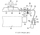
- a disk substrate 81 is transferred and loaded in a film-deposition chamber 80, which is a vacuum chamber, by use of a suction head 87.
- the suction head 87 serves both to transfer the substrate 81 and to hermetically seal the film-deposition chamber 80.
- a plurality of suction pads 41 which hold substrate 81 by sucking are provided on the suction head 87.
- the suction head 87 is fixed to a rotating shaft 86 which is rotatable in a direction indicated by arrow X3, and is movable vertically in a direction indicated by arrow Y3.
- a drive mechanism 82 constituted by a motor 83 and a gear arrangement 84, and an air cylinder 85.
- the suction pads 87a are connected to an external exhaust system 91 by way of an exhaust-and-intake passage 88 formed piercing through the suction head 87 and rotating shaft 86, an outlet 89, and a pipe 90.
- the external exhaust system 91 serves as an operation source which causes the suction pads 87a to capture and release substrate 81.
- the system 91 comprises a bifurcated pipe 92, valves 93a and 93b, and an exhaust pump 94 such as a vacuum pump.
- the above-described substrate loading apparatus 95 receives substrate 81 from a plurality of suction pads 96 of a conveyor-type transferring apparatus (not shown), and loads the thus received substrate 81 in the film-deposition chamber 80 shown in Figure 10.
- the valve 93a is opened so as to cause the suction pads 87a to capture substrate 81.
- the rotating shaft 86 is driven by the motor 83 to rotate by about 180 degrees. As a result, the thus captured substrate 81 is caused to face the film-deposition chamber 80.
- suction head 87 is moved down toward film-deposition chamber 80 by use of the air cylinder 85. Thereafter, valve 93a is closed, and valve 93b is opened to introduce the atmosphere. As a result, substrate 81 is transferred in film-deposition chamber 80.
- the length of pipe 90 must be increased.
- the lengthy pipe 90 has disadvantages such that a large space is required for pipe 90 to achieve the torsional swiveling motions. Further, these motions of pipe 90 are dangerous for the operator.
- suction head 87 carries only a single sheet of substrate 81 at a time.
- the loading cycle speed of the apparatus can be increased only by the increase of the rotation speed of the drive mechanism 82. This inevitably limits the increase of the loading cycle speed. Therefore, the improvement of the loading apparatus has been desired.
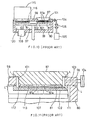
- Figure 10 shows the conventional film-deposition chamber 80 which comprises an upper wall plate 98, a load-lock section 99, and a sputtering section 100. Further, a load-lock chamber 101 is formed in the upper wall plate 98 at a position over the load-lock section 99.
- the load-lock chamber 101 which is shown in an enlarged cross-sectional view of Figure 11, serves as a boundary chamber between the atmospheric pressure and a vacuum when substrate 81 to be sputtered is delivered to a susceptor 102 from suction head 87 or when sputtered substrate 81 is delivered to suction head 87 from susceptor 102.
- a passage 103 which serves both to exhaust and intake, is formed in the upper wall plate 98.
- the passage 103 is connected to an external rotary pump 105 through a bifurcated pipe 104, a valve 106a and a pipe 109.
- valve 81 When substrate 81 is delivered to susceptor 102 from suction head 87, valve 81 is opened to coarsely exhaust load-lock chamber 101 to a vacuum of an intermediate degree, which is against the sucking force of suction pads 87a. Thus, substrate 81 can be delivered to susceptor 102 from suction head 87. Thereafter, a transferring table 107, to which susceptor 102 is fixed, is moved downward. Further, film-deposition chamber 80 and load-lock chamber 101 are still exhausted to a vacuum of a higher degree by use of an exhaust vent 108.
- substrate 81 is held by suction pads 87a and a ring-shaped rim 111 formed in the periphery of suction head 87, as shown in Figure 11. This is because suction head 87 must hold substrate 81 without touching its surface on which information has been recorded.
- the conventional substrate loading apparatus has the following disadvantages. Specifically, when sputtered substrate 81 is delivered to suction head 87 from susceptor 102, the pressure in load-lock chamber 101 is changed to the atmospheric pressure. On the other hand, substrate 81 has been captured by suction pads 87a and in close contact with rim 111. This forms a hermetically sealed space 112 interposing substrate 81 for a certain period, and the pressure in the space 112 differs from the atmospheric pressure in this period. Thus, substrate 81 might be deformed by bending into a shape illustrated by the dotted line 113. As a result, the information-recorded surface of substrate 81 might be directly touched to suction head 87 and damaged.
- Such damage to the information-recorded surface of substrate 81 can also occur even when substrate 81 is delivered to susceptor 102 from suction head 87. This is because susceptor 102 receives substrate 81 in a plane-contact manner. Even a minute scar on the information-recorded surface of substrate 81 causes substrate 81 per se to be a defect. Thus, the improvement, in which such undesirable damage that can occur in the process of transferring is avoided, has been desired.
- suction head 87 to which pipe 90 for exhaust and intake is connected (see Figure 9), is moved in turn-over reciprocating motions.
- suction head drive mechanism 82 to which pipe 90 for exhaust and intake is connected (see Figure 9)
- suction head drive mechanism 82 to which pipe 90 for exhaust and intake is connected (see Figure 9)
- substrate loading is performed in a sheet-by-sheet manner.
- the speed increase of substrate loading is inevitably limited. If an attempt is made to increase the speed of substrate loading, the load applied to suction head arive mechanism 82 is still increased.
- the information-recorded surface of substrate 81 might be damaged while being received and delivered in load-lock chamber 101 because of deformation caused by the pressure difference between both sides of substrate 81.
- the prior art document FR-A-2 491 381 discloses a device for automatically transferring small pieces such as electronic components via a transfer head which is provided with a pair of suction nozzles. Said suction nozzles are supported on said transfer head in a manner so as to be rotatable around a common axis extending perpendicular to the pivot axis of said transfer head. Each of said rotatable suction nozzles is communicating with an associated suction pipe which is connected with its one end to said transfer head and with its other end to a pivot structure. Said pivot structure is formed with a suction passage which is communicating with a stationary suction channel when said suction nozzle is pivoted into a workpiece transfer position.
- a loading apparatus having a suction-hold mechanism, comprising a suction head having a plurality of suction pads for holding an object to be transferred, a rotation mechanism for rotating the suction head, a pipe connected to the suction pads, and a fixed exhaust system connected to the pipe, the loading apparatus transferring the object from a first position to a second position along a direction crossing the rotating shaft of the rotation mechanism, the improvement of the apparatus comprising:
- the object to be transferred is preferable to be disk-or sheet-shaped.
- any complicated cubic objects may be applicable as long as they can be appropriately sucked.
- the loading apparatus is applied to a continuous sputtering system in which an aluminum film is deposited on each of CD substrates by use of a sputtering technique.
- the flexible pipes are wound around the rotating shaft, and then connected to the external exhaust-and-intake systems.
- the entire apparatus can be structured in a compact configuration.
- a shock absorber is provided to absorb the shock upon the turn of the suction head, and to lighten the load applied to the drive mechanism.
- a plurality of suction pads are provided on both surfaces of the suction head.
- the peripheral portions of both the suction head and the susceptor are formed so as to be lower than their respective center portions.
- the substrate is supported by a plurality of convex portions provided in the periphery of the susceptor. Assume that the imaginary lines, which are connected between any two of the convex portions opposing to each other, pass through the center of the substrate. In this case, the substrate is easily caused to rotate about the center line which supports the substrate. Thus, the substrate might be placed on the susceptor in an inclined state. To avoid this, the number of the convex portions are determined to be odd numbers whereby the imaginary lines connected between any two of the convex portions do not pass through the center of the substrate. As a result, the substrate can be transferred safely and assuredly without inclining.
- Figure 1 through Figure 3 are schematic configuration diagram illustrating a first embodiment of a substrate loading apparatus according to the present invention.
- a large number of substrates 11 of CD and the like are sequentially transferred by an external transferring apparatus 10, e.g., a belt-conveyor and the like.
- the thus transferred substrates 11 are captured in a sheet-by sheet manner by suction pads 15 of a substrate transferring apparatus 13, which is rotatable about a shaft 14 (in a direction indicated by arrow X1) and is movable vertically in a direction indicated by arrow Y1.
- the thus captured substrate 11 is transferred to a substrate loading apparatus 16.
- the substrate loading apparatus 16 receives substrate 11 and load it into an internal transferring apparatus 21 provided in a film-deposition chamber 20 through a load-lock chamber 23.
- the loading of substrate 11 is performed by use of suction pads 18a and 18b provided on both surfaces of a suction head 17.
- the film-deposition chamber 20 comprises an upper wall plate 24, a load-lock section 25 and a sputtering section 26, as shown in Figure 1.
- the load-lock chamber 23 is formed in the upper wall plate 24 at a position over the load-lock section 25.
- substrate 11 is placed on a susceptor 28 of a transferring table 27, and transferred to the sputtering section 26 from the load-lock section 25.
- the transferring of substrate 11 is performed by the rotation of transferring table 27.
- An opening 29 is provided in the upper wall plate 24 at a position over the sputtering section 26, and a sputtering source chamber 30 is disposed at a position over the opening 29. Further, a mask 54 which receives substrate 11 is attached to opening 29. An aluminum film is deposited on the upper surface of substrate 11 which is being in close contact with the lower surface of mask 31. The film-deposition is performed in a short period of about 2 seconds. The sputtering source chamber 30 is exhausted through an exhaust vent 32 of film-deposition chamber 20 while substrate 11 is not being in close contact with mask 31.
- the load-lock chamber 23 formed in upper wall plate 24 serves as a boundary chamber between the atmosphere and a vacuum when substrate 11 is delivered to susceptor 27 from suction head 17 and when sputtered substrate 11 is delivered to suction head 17 from susceptor 27.
- the loading apparatus 16 comprises a plurality of suction pads 18a and 18b provided on both surfaces of the disc-shaped suction head 17, a pair of passages 34a and 34b connected respectively to suction pads 18a and 18b, a pair of pipes 35a and 35b, and a pair of external exhaust systems 40a and 40b fixedly installed outside.
- the pipes 35a and 35b are made of synthetic resin having colors different from each other for the ease of discrimination, and are flexible, hermetic and translucent.
- Each of pipes 35a and 35b has one end connected respectively to outlets 37a and 37b provided in the radial direction of rotating shaft 36. Further, pipes 35a and 35b are wound relatively loosely by plural turns around the circumference of rotating shaft 36. The other ends of pipes 35a and 35b are respectively connected to the external exhaust systems 40a and 40b.
- the capture and release of substrate 11 in the loading apparatus 16 are performed by the open-and-close operations of valves 42a, 42b, 43a and 43b of bifurcated pipes 41a and 41b and the operations of vacuum pumps 44a and 44b in the external exhaust systems 40a and 40b. These operations are performed cooperatively with the operations of suction-head drive mechanism 45, substrate transferring apparatus 13 shown in Figure 1, and internal transferring apparatus 21 in film-deposition chamber 20. The entire cooperative operations are controlled in accordance with control signals produced from a control apparatus (not shown).
- a plurality of suction pads 18a and 18b are provided on both surfaces of suction head 17 so as to constitute two substrate transferring systems.
- pipes 35a and 35b are wound around the circumference of rotating shaft 36 in a coil-shaped fashion, and then connected to the external exhaust systems 40a and 40b.
- the thus received momentum thereof can be absorbed in a circumferential direction of the coil of pipes 35a and 35b.
- shearing forces applied to pipes 35a and 35b per se become smaller.
- the rotational reciprocating motions applied to pipes 35a and 35b are received in the circumferential direction of the coil.
- such motions are changed into smaller expansion and contraction in the radial directions of pipes 35a and 35b.
- a stopper mechanism 49 which comprises a disc-shaped stopper 47 provided at the end of rotating shaft 36 and a screw 48, serves to prevent the wound pipes 35a and 35b from falling off, and to incorporate the same in a compact space.
- suction-head drive mechanism 45 is structured in the following manner. Specifically, a rack 51 is engaged with a pinion 50 fixed to rotating shaft 36. The rack 51 is slidably reciprocated by high-pressure air supplied alternately through pipes 52. Thus, the linear reciprocating motions of rack 51 can be changed into the rotational reciprocating motions of rotating shaft 36 in a range of about 180 degrees.
- a pair of shock absorbers 53 and 54 are provided to absorb the shock upon the turn of rotating shaft 36, which is caused by the inertia moment of suction head 17. This alleviates the load applied to pinion 50 and rack 51.
- shock absorbers 53 and 54 are fixed to the movable block of air-cylinder 55. Further, shock absorbers 53 and 54, in which rubber materials 56 and 57 are respectively filled, are situated on both sides of rotating shaft 36. An arm 58 is fixed to rotating shaft 36, and a top head portion 58a of arm 58 hits shock absorbers 53 and 54 each time suction head 17 travels in a direction indicated by arrow Y and turns. As a result, each shock upon the turn of suction head 17 can be absorbed by either one of shock absorbers 53 or 54.
- shock absorbers 53 and 54 can be replaced with other elastic means, e.g., coil-springs incorporated in concave portions filled with oil.
- a load-lock chamber 23 is formed in an upper wall plate 24 of a film-deposition chamber 20. Further, as shown in an enlarged cross-sectional view of Figure 5, an exhaust-and-intake passage 60 having one end exposed to load-lock chamber 23 is laterally formed in upper wall plate 24.
- a suction head 17 for transferring substrate 11 is disc-shaped, and has two surfaces on which plural suction pads 18a and 18b are provided to capture substrates 11. The peripheral portions of the respective surfaces of suction head 17 are lower than the center portions thereof such that bevelled portions 61 are formed in a taper fashion.
- substrate 11 which has been captured and transferred by suction pads 18b, is delivered to a susceptor 28 of a transferring table 27 through load-lock chamber 23.
- a valve 62 is opened, and load-lock chamber 23 is exhausted by use of an exhaust pump 64 to be a vacuum.
- substrate 11 is released from suction pads 18b, and then placed on susceptor 28.
- the surface of susceptor 28, on which substrate 11 is placed has a peripheral portion formed lower than the center portion thereof.
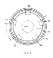
- a plurality of convex portions 63 are provided in the perpheral portion of susceptor 28 so as to support substrate 11 without touching its surface on which information has been recorded.
- susceptor 28 has an odd number (e.g., five) of convex portions 63 separated at equal distances t, as shown in Figure 6. All the imaginary straight lines connected between any two convex portions 63 do not pass through the center P of substrate 11. Thus, a two-point support on the line passing through the center P (i.e., both extreme ends on the diameter) can be avoided. As a result, the undesirable rotation or shift of substrate 11 can be effectively prevented. Further, the distances t between adjacent convex portions 63 are sufficiently large so that the atmosphere can be smoothly introduced into the space between susceptor 28 and substrate 11. Thus, the pressure difference between both sides of substrate 11 never can occur.
- substrate 11 is transferred to suction head 17 from susceptor 28.
- valve 62 is closed, and the other valve (not shown) is opened so as the introduce the atmosphere into load-lock chamber 23.
- the peripheral portions of both surfaces of suction head 17 are formed lower than the center portions thereof.
- the peripheral portion of suction head 17 is separated from substrate 11.
- the atmosphere can be easily introduced into the space between substrate 11 and suction had 17. This can avoid the pressure difference between both sides of substrate 11.
- substrate 11 is free from being deformed by bending unlike in the case of the conventional loading apparatus. Further, the surface of substrate 11, on which information has been recorded, does not touch suction head 17, so that the surface is free from damage.
- suction head 17 has a bevelled portion 61, as shown in Figure 5.
- an exhaust-and-intake passage 60 communicated to load-lock chamber 23 may also be formed in a more shortened configuration without a bifurcated pipe 65 installed outside.
- a common passage 60 and bifurcated passages 66a and 66b are formed in an upper wall plate 24. Further, bifurcated passages 66a and 66b have one end connected to common passage 60, and two other ends connected respectively to external pipes (later described in detail). The bifurcated passages 66a and 66b are respectively bent downward at their midway points. In this embodiment, bifurcated passages 66a and 66b respectively serve as an exhaust pipe and an intake pipe with respect to load-lock chamber 23.
- the wall-of film-deposition chamber 20 extends in a block fashion to upper wall plate 24 so as to make close contact, and two concave-shaped manifolds 67a and 67b are formed in the thus extended wall of film-deposition chamber 20. Further, two ends of bifurcated passages 66a and 66b are exposed respectively to manifolds 67a and 67b through valve members 71a and 71b of a pair of valve mechanisms 70a and 70b.
- valve mechanisms 70a and 70b have cylinders 72b and 72b coupled respectively to valve members 71a and 71b.
- the valve mechanisms 70a and 70b serve to perform the open-and-close operations of the outlet ends of bifurcated passages 66a and 66b.
- a wall surface 73 of upper wall plate 24, on which the outlet ends of bifurcated passages 66a and 66b are disposed serves also as inner wall surface of manifolds 67a and 67b.
- the valve mechanism can be structured in a compact configuration.
- reference characters L represent O-rings for sealing.
- suction head 17 having both surfaces on which suction pads 18a and 18b are respectively provided is applied to the turn-over type substrate loading apparatus.
- the present invention is not limited to this but can also be applied to a pick-and place type substrate loading apparatus which employs a suction head having only one surface on which suction pads are provided.
- the loading apparatus according to the present invention has been applied to the sputtering system.
- the present invention is not limited to this but can also be applied to an etching system, a semiconductor wafer-processing system and the like as long as the applications are cases wherein a load-lock chamber is formed in the wall of an apparatus and the delivery and reception of an object are performed in the load-lock chamber.
- the same advantages as those in the respective embodiments can also be obtained.
- the load-lock type apparatus can efficiently transfer an object to be processed without damage. This can be achieved by the simple improvement of the suction head.
- the apparatus of this invention can be widely used in many applications other than the sputtering system, and has significant advantages in terms of practical applications.
Landscapes
- Engineering & Computer Science (AREA)
- Mechanical Engineering (AREA)
- Manufacturing & Machinery (AREA)
- Physical Vapour Deposition (AREA)
- Container, Conveyance, Adherence, Positioning, Of Wafer (AREA)
- Feeding Of Articles By Means Other Than Belts Or Rollers (AREA)
- Controlling Sheets Or Webs (AREA)
Description
Claims (11)
- Loading apparatus having a suction-hold mechanism, comprising a suction head (17) having a number of suction pads (18a) communicating with a stationary exhaust system via a flexible pipe for holding an object to be transferred, a rotation mechanism (16) for rotating said suction head (17) around an axis (X2) of a rotating shaft (36),characterized in thatrotating means (50, 51) for rotating said suction head (17) so as to turn over at a first position,and means for reciprocating said suction head (17) between first and second positions so as to transfer said object therebetween along a direction transverse to the rotating shaft (36) of said rotation mechanism,
said suction head (17) includes two surfaces facing in opposite directions, each surface having a number of suction pads (18a, 18b) for suck-holding said object and for receiving and delivering said object at said first and second positions, said suction pads (18a, 18b) are communicating with the exhaust system (40a, 40b) via a pair of flexible pipes (35a, 35b) wherein said flexible pipes (35a, 35b) being wound along the circumference of said rotating shaft (36). - Loading apparatus according to claim 1, characterized by a valve means (42a, 43a, 42b, 43b) for selectively operating said suction pads (18a, 18b) so as to selectively suck the respective object.
- Loading apparatus according to claim 1 or 2, characterized in that said suction head (17) is construed so as to transport a disk substrate (11) as said object by suck-holding between a first position at which said disk substrate (11) is received, to a second position situated in a load-lock chamber (23) provided in a portion of a vacuum chamber, said load-lock chamber (23) being used when a disk substrate (11) is transferred into said vacuum chamber and transferred out therefrom, wherein said rotating means (50, 51) are construed such as to pivot the surfaces of said suction head (17) to alternately face said load-lock chamber (23) at a position separated from said load-lock chamber (23), wherein said rotating means (50, 51) are rotating said suction head (17) about an axis (X2) extending in a direction parallel to said surfaces of said suction head (17).
- Load apparatus according to claim 3, characterized by a shock absorber for absorbing a shock upon the stoppage of said suction head (17) in rotational reciprocating motions.
- Loading apparatus according to claim 4, characterized in that said suction head (17) is construed so as to hold said substrate (11) to be transferred into said vacuum chamber while the suction pads on the other surface of said suction head (17) are provided to hold a substrate (11) to be transferred out.
- Loading apparatus according to claim 1, characterized in that the rotation of said suction head (17) are half-turn reciprocating motions.
- Loading apparatus according to at least one of claims 1 to 6, characterized in that said apparatus includes a drive mechanism for giving said suction head repetitive vertical motions and rotational reciprocating motions around an axis (X2) of a shaft (36) at a position separate from said vacuum chamber.
- Loading apparatus according to at least one of claims 1 to 7, characterized in that said rotational reciprocating motions are performed by use of the linear reciprocating motions of a rack (51) engaged with a pinion (50) fixed to the rotating shaft (36) of said drive mechanism (45, 46, 50, 51).
- Loading apparatus according to claim 8, characterized in that said pipes (35a, 35b) are made of synthetic resin having colours different from each other, each pipe (35a, 35b) having one end connected to openings (37a, 37) provided in the rotating shaft (36) in a direction perpendicular to the axis (X2) of the shaft (36), said pipe (35, 35b) being wound around the circumference of the shaft (36) and prevented from falling off by a stopper (47) attached to the end of the shaft (36).
- Loading apparatus according to claim 9, characterized in that each of the surfaces of said suction head (17) has a periphery thinner than the center portion thereof, and that a transferring table (27) is provided in said vacuum chamber for supporting the substrate (11), said table (27) having a surface on which the substrate (11) is placed, the surface having a periphery thinner than the center portion thereof and also having a plurality of convex portions (63) formed in said periphery for supporting the substrate (11).
- Loading apparatus according to claim 10, characterized in that the number of convex portions (63) formed in the periphery of the transferring table is determined to be an odd number.
Applications Claiming Priority (2)
| Application Number | Priority Date | Filing Date | Title |
|---|---|---|---|
| JP336690/90 | 1990-11-30 | ||
| JP2336690A JPH0639697B2 (en) | 1990-11-30 | 1990-11-30 | Substrate loading device |
Publications (2)
| Publication Number | Publication Date |
|---|---|
| EP0487848A1 EP0487848A1 (en) | 1992-06-03 |
| EP0487848B1 true EP0487848B1 (en) | 1998-01-07 |
Family
ID=18301802
Family Applications (1)
| Application Number | Title | Priority Date | Filing Date |
|---|---|---|---|
| EP91115580A Expired - Lifetime EP0487848B1 (en) | 1990-11-30 | 1991-09-13 | A loading apparatus having a suction-hold mechanism |
Country Status (4)
| Country | Link |
|---|---|
| US (1) | US5336029A (en) |
| EP (1) | EP0487848B1 (en) |
| JP (1) | JPH0639697B2 (en) |
| DE (1) | DE69128612T2 (en) |
Cited By (1)
| Publication number | Priority date | Publication date | Assignee | Title |
|---|---|---|---|---|
| CN107104072A (en) * | 2017-04-25 | 2017-08-29 | 京东方科技集团股份有限公司 | One kind inhales ball |
Families Citing this family (33)
| Publication number | Priority date | Publication date | Assignee | Title |
|---|---|---|---|---|
| DE4225248A1 (en) * | 1992-07-31 | 1994-02-03 | Erfurt Umformtechnik Gmbh | Blank feeder for a press |
| DE4232959C2 (en) * | 1992-10-01 | 2001-05-10 | Leybold Ag | Device for introducing and discharging disc-shaped substrates |
| FI92170C (en) * | 1993-02-09 | 1994-10-10 | Valmet Paper Machinery Inc | Grab to grip the end tags |
| KR100267617B1 (en) * | 1993-04-23 | 2000-10-16 | 히가시 데쓰로 | Vacuum process apparatus and vacuum processing method |
| ES2075800B1 (en) * | 1993-10-14 | 1998-07-16 | Torres Martinez M | INSTALLATION FOR THE TRANSPORT AND TURNING OF LARGE PARTS. |
| US5496409A (en) * | 1994-07-18 | 1996-03-05 | United Microelectronics Corporation | Particle contamination apparatus for semiconductor wafer processing |
| US5599268A (en) * | 1994-07-20 | 1997-02-04 | Tetra Laval Holdings & Finance S.A. | Belt driven linear transport apparatus for packaging machine |
| ES2115466B1 (en) * | 1994-09-22 | 1999-02-16 | Torres Martinez M | LARGE PIECE CONVEYOR AND TURNER. |
| JP3354761B2 (en) * | 1995-08-30 | 2002-12-09 | オリジン電気株式会社 | Disk coating equipment |
| TW401582B (en) * | 1997-05-15 | 2000-08-11 | Tokyo Electorn Limtied | Apparatus for and method of transferring substrates |
| JP2000133693A (en) * | 1998-08-19 | 2000-05-12 | Shibaura Mechatronics Corp | Vacuum device and mechanism for driving the same |
| DE10062011B4 (en) * | 2000-12-13 | 2005-02-24 | Infineon Technologies Ag | holder |
| WO2002095795A2 (en) * | 2001-05-18 | 2002-11-28 | Mattson Thermal Products Gmbh | Device for receiving plate-shaped objects |
| JP3810714B2 (en) * | 2002-07-29 | 2006-08-16 | エスペック株式会社 | Thin layer substrate manufacturing method, thin layer substrate transfer device, and thin layer substrate transfer suction pad |
| US6837664B2 (en) | 2002-09-10 | 2005-01-04 | Douglas Machine, Inc. | Multiple head rotary set-up |
| DE102005038976B4 (en) * | 2004-02-17 | 2016-08-04 | Josef Moser | Movement device with sinusoidal motion sequence |
| DE102006002367B3 (en) * | 2006-01-17 | 2007-10-04 | Mühlbauer Ag | Apparatus and method for transferring a plurality of chips from a wafer to a substrate |
| DE102007001722B4 (en) * | 2007-01-11 | 2009-03-12 | Hubertus Heigl | Device for picking up, transporting and sorting electronic components |
| US8167524B2 (en) * | 2007-11-16 | 2012-05-01 | Asm Assembly Automation Ltd | Handling system for inspecting and sorting electronic components |
| CN102039279A (en) * | 2009-10-15 | 2011-05-04 | 梁启明 | Intravenous infusion needle hose sequencing device |
| US9920418B1 (en) * | 2010-09-27 | 2018-03-20 | James Stabile | Physical vapor deposition apparatus having a tapered chamber |
| CN103249258B (en) * | 2012-02-06 | 2015-12-16 | 无锡华润安盛科技有限公司 | Substrate apparatus for automatically loading |
| JP6059565B2 (en) * | 2013-03-13 | 2017-01-11 | 三星ダイヤモンド工業株式会社 | Adsorption reversing device |
| CN103879747B (en) * | 2014-03-12 | 2017-01-04 | 黟县越驰科技电子有限公司 | The feeding device of magnet former |
| CN104625685B (en) * | 2015-02-16 | 2016-09-14 | 吴中经济技术开发区越溪斯特拉机械厂 | A kind of rotating and moving device of configuration-changeable of mobile phone display screen pneumatic machinery mobile device |
| CN104649008B (en) * | 2015-02-16 | 2017-03-01 | 吴中经济技术开发区越溪斯特拉机械厂 | A kind of mobile phone display screen pneumatic machinery mobile device |
| WO2017142531A1 (en) * | 2016-02-17 | 2017-08-24 | Wheelabrator Group, Inc. | Turnover mechanism of a conveyor system of a blast wheel machine |
| JP6727049B2 (en) * | 2016-07-12 | 2020-07-22 | 東京エレクトロン株式会社 | Joining system |
| CN106672619A (en) * | 2017-02-15 | 2017-05-17 | 苏州迈瑞微电子有限公司 | Molding compound transfer equipment and method |
| CN107195577B (en) * | 2017-05-08 | 2019-11-05 | 深圳市华星光电技术有限公司 | Substrate turnover device and its method for being detached from substrate |
| FR3084518B1 (en) * | 2018-07-25 | 2020-10-30 | Commissariat Energie Atomique | GRIPPING DEVICE FOR A SINGLE-LAYER OR MULTI-LAYER STRUCTURE INCLUDING A ROTARY AND THERMAL GRIPPING ELEMENT |
| CN110683354A (en) * | 2019-09-26 | 2020-01-14 | 苏州领裕电子科技有限公司 | Novel annular highlight product transferring system and method |
| CN112722790A (en) * | 2021-02-04 | 2021-04-30 | 四川通安实业有限公司 | License plate die assembly's upset snatchs structure |
Family Cites Families (12)
| Publication number | Priority date | Publication date | Assignee | Title |
|---|---|---|---|---|
| US1447428A (en) * | 1921-10-31 | 1923-03-06 | Ramsay Erskine | Automatic rotary dump |
| US3071258A (en) * | 1959-04-09 | 1963-01-01 | Continental Can Co | Bundle inverting means |
| IT1064030B (en) * | 1976-06-11 | 1985-02-18 | Carle & Montanari Spa | MECHANISM FOR THE WITHDRAWAL AS WELL AS THE STORAGE OF SWEET ITEMS |
| JPS5837590Y2 (en) * | 1980-10-08 | 1983-08-24 | ファナック株式会社 | Double hand for shaft work |
| FR2491381A1 (en) * | 1980-10-08 | 1982-04-09 | Rech Const Electroniq Et | Vacuum type micro-electronic component PCB mounting appts. - has shaft on which tubes are rotatably mounted to transfer vacuum while rotating about shaft and principal axes of tube |
| JPS5821665Y2 (en) * | 1980-10-08 | 1983-05-09 | ファナック株式会社 | Through type double hand |
| EP0061505B1 (en) * | 1981-03-26 | 1984-11-28 | Carl Freudenberg Firma | Method of making the cushioned inner sole |
| AU548550B2 (en) * | 1983-03-01 | 1985-12-19 | Dart Industries Inc. | Extensible workpiece manipulator |
| JPS605509A (en) * | 1983-06-24 | 1985-01-12 | Hitachi Ltd | Molecular beam epitaxy equipment |
| US4752180A (en) * | 1985-02-14 | 1988-06-21 | Kabushiki Kaisha Toshiba | Method and apparatus for handling semiconductor wafers |
| FR2597453B1 (en) * | 1986-04-18 | 1988-08-05 | Tech Nles Ste Gle | DEVICE FOR TRANSFERRING OBJECTS, ESPECIALLY GLASS PLATES |
| DE69108079T2 (en) * | 1990-03-30 | 1995-11-02 | Sony Corp | Sputtering system. |
-
1990
- 1990-11-30 JP JP2336690A patent/JPH0639697B2/en not_active Expired - Fee Related
-
1991
- 1991-09-12 US US07/757,982 patent/US5336029A/en not_active Expired - Lifetime
- 1991-09-13 DE DE69128612T patent/DE69128612T2/en not_active Expired - Fee Related
- 1991-09-13 EP EP91115580A patent/EP0487848B1/en not_active Expired - Lifetime
Cited By (1)
| Publication number | Priority date | Publication date | Assignee | Title |
|---|---|---|---|---|
| CN107104072A (en) * | 2017-04-25 | 2017-08-29 | 京东方科技集团股份有限公司 | One kind inhales ball |
Also Published As
| Publication number | Publication date |
|---|---|
| US5336029A (en) | 1994-08-09 |
| JPH0639697B2 (en) | 1994-05-25 |
| DE69128612T2 (en) | 1998-04-23 |
| DE69128612D1 (en) | 1998-02-12 |
| JPH04202775A (en) | 1992-07-23 |
| EP0487848A1 (en) | 1992-06-03 |
Similar Documents
| Publication | Publication Date | Title |
|---|---|---|
| EP0487848B1 (en) | A loading apparatus having a suction-hold mechanism | |
| JP3419457B2 (en) | Articulated arm transfer device | |
| US5280983A (en) | Semiconductor processing system with robotic autoloader and load lock | |
| JPH0261064A (en) | Apparatus for coating substrate by merry-go-round system | |
| KR100832212B1 (en) | Vacuum processing apparatus | |
| JPH0366580A (en) | Device for holding and carrying disc | |
| CN101019220A (en) | Advanced low cost high throughput processing platform | |
| GB2262656A (en) | Processing semiconductor wafers | |
| KR20090083452A (en) | Rotation introducing mechanism, substrate transfer device, and vacuum treating apparatus | |
| USRE40192E1 (en) | Vacuum process apparatus | |
| KR20010074921A (en) | Device and method for handling individual wafers | |
| US6679675B2 (en) | Method and apparatus for processing wafers | |
| JP3632812B2 (en) | Substrate transfer equipment | |
| JPH07113151B2 (en) | Equipment for loading and unloading workpieces in the vacuum chamber | |
| JP4557418B2 (en) | Multi-layer film forming equipment | |
| JP2511566B2 (en) | Transfer device | |
| US20030106789A1 (en) | Chamber for the transport of workpieces in a vacuum atmosphere, a chamber combination and a method for transporting a workpiece | |
| JP3325749B2 (en) | Vacuum processing equipment | |
| US20040221811A1 (en) | Method and apparatus for processing wafers | |
| KR930009991B1 (en) | Apparatus for the inward and outward transfer of a workpiece in a vacuum chamber | |
| JPH04202776A (en) | Loading device | |
| JP2500820B2 (en) | Adsorption mechanism | |
| JPH0463277A (en) | Piping device for repeated rotating mechanism | |
| JPH04129916A (en) | Conveying device | |
| JP4350653B2 (en) | Optical disc manufacturing method and optical disc manufacturing apparatus |
Legal Events
| Date | Code | Title | Description |
|---|---|---|---|
| PUAI | Public reference made under article 153(3) epc to a published international application that has entered the european phase |
Free format text: ORIGINAL CODE: 0009012 |
|
| 17P | Request for examination filed |
Effective date: 19910913 |
|
| AK | Designated contracting states |
Kind code of ref document: A1 Designated state(s): DE FR GB |
|
| RAP1 | Party data changed (applicant data changed or rights of an application transferred) |
Owner name: SHIBAURA ENGINEERING WORKS CO., LTD. Owner name: SONY CORPORATION |
|
| 17Q | First examination report despatched |
Effective date: 19950131 |
|
| GRAG | Despatch of communication of intention to grant |
Free format text: ORIGINAL CODE: EPIDOS AGRA |
|
| GRAG | Despatch of communication of intention to grant |
Free format text: ORIGINAL CODE: EPIDOS AGRA |
|
| GRAH | Despatch of communication of intention to grant a patent |
Free format text: ORIGINAL CODE: EPIDOS IGRA |
|
| GRAH | Despatch of communication of intention to grant a patent |
Free format text: ORIGINAL CODE: EPIDOS IGRA |
|
| GRAA | (expected) grant |
Free format text: ORIGINAL CODE: 0009210 |
|
| AK | Designated contracting states |
Kind code of ref document: B1 Designated state(s): DE FR GB |
|
| REF | Corresponds to: |
Ref document number: 69128612 Country of ref document: DE Date of ref document: 19980212 |
|
| ET | Fr: translation filed | ||
| PLBE | No opposition filed within time limit |
Free format text: ORIGINAL CODE: 0009261 |
|
| STAA | Information on the status of an ep patent application or granted ep patent |
Free format text: STATUS: NO OPPOSITION FILED WITHIN TIME LIMIT |
|
| 26N | No opposition filed | ||
| REG | Reference to a national code |
Ref country code: GB Ref legal event code: IF02 |
|
| PGFP | Annual fee paid to national office [announced via postgrant information from national office to epo] |
Ref country code: GB Payment date: 20080924 Year of fee payment: 18 |
|
| PGFP | Annual fee paid to national office [announced via postgrant information from national office to epo] |
Ref country code: DE Payment date: 20081030 Year of fee payment: 18 |
|
| PGFP | Annual fee paid to national office [announced via postgrant information from national office to epo] |
Ref country code: FR Payment date: 20080922 Year of fee payment: 18 |
|
| GBPC | Gb: european patent ceased through non-payment of renewal fee |
Effective date: 20090913 |
|
| REG | Reference to a national code |
Ref country code: FR Ref legal event code: ST Effective date: 20100531 |
|
| PG25 | Lapsed in a contracting state [announced via postgrant information from national office to epo] |
Ref country code: DE Free format text: LAPSE BECAUSE OF NON-PAYMENT OF DUE FEES Effective date: 20100401 Ref country code: FR Free format text: LAPSE BECAUSE OF NON-PAYMENT OF DUE FEES Effective date: 20090930 |
|
| PG25 | Lapsed in a contracting state [announced via postgrant information from national office to epo] |
Ref country code: GB Free format text: LAPSE BECAUSE OF NON-PAYMENT OF DUE FEES Effective date: 20090913 |