EP0487777B1 - Calibration unit with integral joint for a plastic elements extruder - Google Patents
Calibration unit with integral joint for a plastic elements extruder Download PDFInfo
- Publication number
- EP0487777B1 EP0487777B1 EP90122932A EP90122932A EP0487777B1 EP 0487777 B1 EP0487777 B1 EP 0487777B1 EP 90122932 A EP90122932 A EP 90122932A EP 90122932 A EP90122932 A EP 90122932A EP 0487777 B1 EP0487777 B1 EP 0487777B1
- Authority
- EP
- European Patent Office
- Prior art keywords
- calibrating
- calibration unit
- extruder
- parts
- members
- Prior art date
- Legal status (The legal status is an assumption and is not a legal conclusion. Google has not performed a legal analysis and makes no representation as to the accuracy of the status listed.)
- Expired - Lifetime
Links
Images
Classifications
-
- B—PERFORMING OPERATIONS; TRANSPORTING
- B29—WORKING OF PLASTICS; WORKING OF SUBSTANCES IN A PLASTIC STATE IN GENERAL
- B29C—SHAPING OR JOINING OF PLASTICS; SHAPING OF MATERIAL IN A PLASTIC STATE, NOT OTHERWISE PROVIDED FOR; AFTER-TREATMENT OF THE SHAPED PRODUCTS, e.g. REPAIRING
- B29C48/00—Extrusion moulding, i.e. expressing the moulding material through a die or nozzle which imparts the desired form; Apparatus therefor
- B29C48/25—Component parts, details or accessories; Auxiliary operations
- B29C48/88—Thermal treatment of the stream of extruded material, e.g. cooling
- B29C48/90—Thermal treatment of the stream of extruded material, e.g. cooling with calibration or sizing, i.e. combined with fixing or setting of the final dimensions of the extruded article
-
- B—PERFORMING OPERATIONS; TRANSPORTING
- B29—WORKING OF PLASTICS; WORKING OF SUBSTANCES IN A PLASTIC STATE IN GENERAL
- B29C—SHAPING OR JOINING OF PLASTICS; SHAPING OF MATERIAL IN A PLASTIC STATE, NOT OTHERWISE PROVIDED FOR; AFTER-TREATMENT OF THE SHAPED PRODUCTS, e.g. REPAIRING
- B29C48/00—Extrusion moulding, i.e. expressing the moulding material through a die or nozzle which imparts the desired form; Apparatus therefor
- B29C48/03—Extrusion moulding, i.e. expressing the moulding material through a die or nozzle which imparts the desired form; Apparatus therefor characterised by the shape of the extruded material at extrusion
- B29C48/09—Articles with cross-sections having partially or fully enclosed cavities, e.g. pipes or channels
-
- B—PERFORMING OPERATIONS; TRANSPORTING
- B29—WORKING OF PLASTICS; WORKING OF SUBSTANCES IN A PLASTIC STATE IN GENERAL
- B29C—SHAPING OR JOINING OF PLASTICS; SHAPING OF MATERIAL IN A PLASTIC STATE, NOT OTHERWISE PROVIDED FOR; AFTER-TREATMENT OF THE SHAPED PRODUCTS, e.g. REPAIRING
- B29C48/00—Extrusion moulding, i.e. expressing the moulding material through a die or nozzle which imparts the desired form; Apparatus therefor
- B29C48/03—Extrusion moulding, i.e. expressing the moulding material through a die or nozzle which imparts the desired form; Apparatus therefor characterised by the shape of the extruded material at extrusion
- B29C48/12—Articles with an irregular circumference when viewed in cross-section, e.g. window profiles
-
- B—PERFORMING OPERATIONS; TRANSPORTING
- B29—WORKING OF PLASTICS; WORKING OF SUBSTANCES IN A PLASTIC STATE IN GENERAL
- B29C—SHAPING OR JOINING OF PLASTICS; SHAPING OF MATERIAL IN A PLASTIC STATE, NOT OTHERWISE PROVIDED FOR; AFTER-TREATMENT OF THE SHAPED PRODUCTS, e.g. REPAIRING
- B29C48/00—Extrusion moulding, i.e. expressing the moulding material through a die or nozzle which imparts the desired form; Apparatus therefor
- B29C48/25—Component parts, details or accessories; Auxiliary operations
- B29C48/88—Thermal treatment of the stream of extruded material, e.g. cooling
- B29C48/911—Cooling
- B29C48/9135—Cooling of flat articles, e.g. using specially adapted supporting means
- B29C48/915—Cooling of flat articles, e.g. using specially adapted supporting means with means for improving the adhesion to the supporting means
- B29C48/916—Cooling of flat articles, e.g. using specially adapted supporting means with means for improving the adhesion to the supporting means using vacuum
-
- B—PERFORMING OPERATIONS; TRANSPORTING
- B29—WORKING OF PLASTICS; WORKING OF SUBSTANCES IN A PLASTIC STATE IN GENERAL
- B29C—SHAPING OR JOINING OF PLASTICS; SHAPING OF MATERIAL IN A PLASTIC STATE, NOT OTHERWISE PROVIDED FOR; AFTER-TREATMENT OF THE SHAPED PRODUCTS, e.g. REPAIRING
- B29C2791/00—Shaping characteristics in general
- B29C2791/004—Shaping under special conditions
- B29C2791/006—Using vacuum
-
- B—PERFORMING OPERATIONS; TRANSPORTING
- B29—WORKING OF PLASTICS; WORKING OF SUBSTANCES IN A PLASTIC STATE IN GENERAL
- B29C—SHAPING OR JOINING OF PLASTICS; SHAPING OF MATERIAL IN A PLASTIC STATE, NOT OTHERWISE PROVIDED FOR; AFTER-TREATMENT OF THE SHAPED PRODUCTS, e.g. REPAIRING
- B29C48/00—Extrusion moulding, i.e. expressing the moulding material through a die or nozzle which imparts the desired form; Apparatus therefor
- B29C48/25—Component parts, details or accessories; Auxiliary operations
- B29C48/88—Thermal treatment of the stream of extruded material, e.g. cooling
- B29C48/90—Thermal treatment of the stream of extruded material, e.g. cooling with calibration or sizing, i.e. combined with fixing or setting of the final dimensions of the extruded article
- B29C48/904—Thermal treatment of the stream of extruded material, e.g. cooling with calibration or sizing, i.e. combined with fixing or setting of the final dimensions of the extruded article using dry calibration, i.e. no quenching tank, e.g. with water spray for cooling or lubrication
-
- B—PERFORMING OPERATIONS; TRANSPORTING
- B29—WORKING OF PLASTICS; WORKING OF SUBSTANCES IN A PLASTIC STATE IN GENERAL
- B29C—SHAPING OR JOINING OF PLASTICS; SHAPING OF MATERIAL IN A PLASTIC STATE, NOT OTHERWISE PROVIDED FOR; AFTER-TREATMENT OF THE SHAPED PRODUCTS, e.g. REPAIRING
- B29C48/00—Extrusion moulding, i.e. expressing the moulding material through a die or nozzle which imparts the desired form; Apparatus therefor
- B29C48/25—Component parts, details or accessories; Auxiliary operations
- B29C48/88—Thermal treatment of the stream of extruded material, e.g. cooling
- B29C48/911—Cooling
- B29C48/9115—Cooling of hollow articles
- B29C48/912—Cooling of hollow articles of tubular films
- B29C48/913—Cooling of hollow articles of tubular films externally
Definitions
- the invention relates to a calibration unit of an extruder for profiles, which is composed of detachably connected inner and outer caliber parts.
- the invention has for its object to provide a calibration unit of an extruder for profiles, the parts of which can be easily positioned with high dimensional accuracy.
- This object is achieved according to the invention in that at least two parts of the outer caliber parts are connected to one another by an integrated hinge. Each integrated joint should extend over the entire axial length of the caliber.
- the one or more inner caliber parts are detachably connected to one another via an axial link guide.
- the one or more hinged outer caliber parts should be lockable at the ends facing away from the joint or joints with other caliber parts.
- caliber parts are produced in one operation by wire erosion from a stress-free annealed workpiece.
- the calibration unit can be opened and closed easily and quickly when starting up or shutting down or in the event of an extrusion line malfunctioning.
- the integrated joints ensure a high degree of dimensional accuracy without it being necessary to apply special care and time when closing to achieve a high degree of dimensional accuracy.
- the calibration unit according to the invention is therefore suitable for automatic operation.
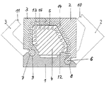
- the calibration unit shown in the drawing consists of three outer parts 1-3 and an inner part 4, which are fixed to each other in the closed state of the calibration unit. They form a cavity 5 between them for the profile to be extruded.
- the outer parts 1 - 3 consist of a base 1 and two side parts 2, 3 which are held there in an articulated manner and can be folded out from the excellent position into the dot-dash position.
- the articulated connection of each of these side parts 2, 3 consists of a circular cylindrical hinge pin 6, 7 molded on a longitudinal edge of each side part 2, 3 and a circular cylindrical bearing shell 8, 9 formed in the base 1.
- the side parts 2, 3 On its other longitudinal edge, have a link-like guide 10, 11, which locks the two side parts 2, 3 in the closed state of the calibration.
- the inner part 4 of the calibration unit is fixed with a dovetail guide 12 on the base 1 in the normal plane to the axial plane. In the axial direction, the inner part 4, like the side parts 2, 3, is locked with respect to the base 1 by means not shown.
- Both in the inner part 4 and in the side parts 2, 3, axial vacuum and / or cooling channels 13-15 are formed adjacent to the cavity 5.
- the individual parts are Wire erosion made from a stress-free annealed steel block. Appropriate path controls are required for the creation of the circular cross-sections of the joints.
Description
Die Erfindung bezieht sich auf eine Kalibriereinheit eines Extruders für Profile, die aus lösbar miteinander verbundenen inneren und äußeren Kaliberteilen zusammengesetzt ist.The invention relates to a calibration unit of an extruder for profiles, which is composed of detachably connected inner and outer caliber parts.
Bei einer bekannten Kalibriereinheit (EP-A-0 207 064) dieser Art sind die einzeln gefertigten Kaliberteile durch Schraubverbindungen oder andere Verbindungsteile zusammengehalten. Ein wesentlicher Nachteil einer solchen Kalibriereinheit besteht darin, daß mit immer höheren Anforderungen an die Maßhaltigkeit die Positionierung der Einzelteile einen erheblichen Aufwand erfordert. Dieser Aufwand kann auch nicht dadurch wesentlich vermindert werden, daß manche Teile über Gelenkscharniere miteinander verbunden sind, denn auch diese Scharniere müssen beim Zusammenbau genau positioniert werden. Hinzu kommt, daß solche Scharniere einen nicht unerheblichen fertigungstechnischen und montagetechnischen Aufwand erfordern und der konstruktiv bedingte Gelenkpunkt ungünstig liegt.In a known calibration unit (EP-A-0 207 064) of this type, the individually manufactured caliber parts are held together by screw connections or other connecting parts. A major disadvantage of such a calibration unit is that the positioning of the individual parts requires considerable effort with increasing demands on dimensional accuracy. This effort can also not be significantly reduced by the fact that some parts are connected to one another via articulated hinges, because these hinges also have to be positioned exactly during assembly. In addition, such hinges have a not inconsiderable manufacturing and assembly technology Require effort and the design-related hinge point is unfavorable.
Der Erfindung liegt die Aufgabe zugrunde, eine Kalibriereinheit eines Extruders für Profile zu schaffen, dessen Teile problemlos mit hoher Maßhaltigkeit positioniert werden können.The invention has for its object to provide a calibration unit of an extruder for profiles, the parts of which can be easily positioned with high dimensional accuracy.
Diese Aufgabe wird erfindungsgemäß dadurch gelöst, daß von den äußeren Kaliberteilen mindestens zwei Teile über ein integriertes Gelenk aufklappbar miteinander verbunden sind. Dabei sollte sich jedes integrierte Gelenk über die gesamte axiale Länge des Kalibers erstrecken.This object is achieved according to the invention in that at least two parts of the outer caliber parts are connected to one another by an integrated hinge. Each integrated joint should extend over the entire axial length of the caliber.
Das oder die inneren Kaliberteile sind nach einer Ausgestaltung der Erfindung über eine axiale Kulissenführung lösbar miteinander verbunden.The one or more inner caliber parts are detachably connected to one another via an axial link guide.
Das oder die aufklappbaren äußeren Kaliberteile sollten an ihren dem beziehungsweise den Gelenken abgewandten Enden kulissenartig mit anderen Kaliberteilen verriegelbar sein.The one or more hinged outer caliber parts should be lockable at the ends facing away from the joint or joints with other caliber parts.
Besonders hat sich bewährt, wenn die Kaliberteile durch Drahterosion aus einem spannungsfrei geglühten Werkstück in einem Arbeitsgang hergestellt sind.It has proven particularly useful if the caliber parts are produced in one operation by wire erosion from a stress-free annealed workpiece.
Die besonderen Vorteile der Erfindung bestehen darin, daß beim An- bzw. Abfahren oder bei Störungen einer Extrusionslinie einfach und schnell die Kalibiereinheit geöffnet und geschlossen werden kann. Die integrierten Gelenke sorgen für eine hohe Maßhaltigkeit, ohne daß es notwendig ist, beim Schließen besondere Sorgfalt und Zeit zur Erzielung einer hohen Maßhaltigkeit aufzubringen. Deshalb eignet sich die erfindungsgemäße Kalibriereinheit für den automatischen Betrieb.The particular advantages of the invention are that the calibration unit can be opened and closed easily and quickly when starting up or shutting down or in the event of an extrusion line malfunctioning. The integrated joints ensure a high degree of dimensional accuracy without it being necessary to apply special care and time when closing to achieve a high degree of dimensional accuracy. The calibration unit according to the invention is therefore suitable for automatic operation.
Im folgenden wird die Erfindung anhand einer ein Ausführungsbeispiel im Querschnitt darstellenden Zeichnung näher erläutert.The invention is explained in more detail below with reference to a drawing showing an exemplary embodiment in cross section.
Die in der Zeichnung dargestellte Kalibriereinheit besteht aus drei äußeren Teilen 1-3 und einem inneren Teil 4, die im geschlossenen Zustand der Kalibriereinheit zueinander fest positioniert sind. Sie bilden zwischen sich einen Hohlraum 5 für das zu extrudierende Profil.The calibration unit shown in the drawing consists of three outer parts 1-3 and an inner part 4, which are fixed to each other in the closed state of the calibration unit. They form a
Die äußeren Teile 1-3 bestehen aus einem Sockel 1 und zwei daran gelenkig gehaltenen, aus der ausgezeichneten Lage in die strichpunktierte Lage aufklappbaren Seitenteilen 2,3. Die gelenkige Verbindung jedes dieser Seitenteile 2,3 besteht aus einem an einem Längsrand eines jeden Seitenteils 2,3 angeformten kreiszylindrischen Gelenkzapfen 6,7 und einer im Sockel 1 ausgebildeten kreiszylindrischen Lagerschale 8,9. An ihrem anderen Längsrand weisen die Seitenteile 2,3 eine kulissenartige Führung 10,11 auf, die im geschlossenen Zustand der Kalibrierung die beiden Seitenteile 2,3 miteinander verriegelt.The outer parts 1 - 3 consist of a
Das innere Teil 4 der Kalibriereinheit ist mit einer Schwalbenschwanzführung 12 auf dem Sockel 1 in der Normalebene zur Axialebene festgelegt. In axialer Richtung sind das Innenteil 4 wie die Seitenteile 2,3 gegenüber dem Sockel 1 mit nicht dargestellten Mitteln verriegelt.The inner part 4 of the calibration unit is fixed with a
Sowohl im Innenteil 4 als auch in den Seitenteilen 2,3 sind dem Hohlraum 5 benachbart axiale Vakuum- und/oder Kühlkanäle 13-15 ausgebildet.Both in the inner part 4 and in the
Um zu einer toleranzarmen, sich aus verschiedenen Teilen zusammensetzenden Kalibriereinheit mit integrierten Gelenken zu kommen, werden die einzelnen Teile durch Drahterosion aus einem spannungsfrei geglühten Stahlblock hergestellt. Hierbei sind entsprechende Bahnsteuerungen für die Erstellung der Kreisquerschnitte der Gelenke notwendig.In order to arrive at a low-tolerance calibration unit made up of different parts with integrated joints, the individual parts are Wire erosion made from a stress-free annealed steel block. Appropriate path controls are required for the creation of the circular cross-sections of the joints.
Claims (5)
- A calibrating unit of an extruder for sections, which is made up of releasably interconnected inner and outer calibrating members (1-4), characterized in that of the outer calibrating members (1-3) at least two members (1, 2 and/or 1, 3) are interconnected via an integrated joint (6, 8 and/or 7, 9).
- A calibrating unit according to claim 1, characterized in that each integrated joint (6, 8; 7, 9) extends over the whole axial length of the calibrating unit.
- A calibrating unit according to claims 1 or 2, characterized in that an inner calibrating member (4) is releasably connected via an axial connecting link guide (12) to another calibrating member (1).
- A calibrating unit according to one of claims 1 to 3, characterized in that at its end remote from the joint (6, 8; 7, 9) each calibrating member (2, 3) which can be hinged open can be locked after the fashion of a connecting link guide to another calibrating member (3; 2).
- A calibrating unit according to one of claims 1 to 4, characterized in that the calibrating members (1-5) are produced in a single operation by wire erosion from a workpiece annealed tension-free.
Priority Applications (1)
| Application Number | Priority Date | Filing Date | Title |
|---|---|---|---|
| AT90122932T ATE119464T1 (en) | 1990-11-30 | 1990-11-30 | CALIBRATION UNIT WITH INTEGRATED JOINT FOR AN EXTRUDER FOR PLASTIC PROFILES. |
Applications Claiming Priority (2)
| Application Number | Priority Date | Filing Date | Title |
|---|---|---|---|
| DE3936226 | 1989-10-31 | ||
| DE4028116A DE4028116A1 (en) | 1989-10-31 | 1990-09-05 | CALIBRATION UNIT WITH INTEGRATED JOINT FOR AN EXTRUDER FOR PLASTIC PROFILES |
Publications (2)
| Publication Number | Publication Date |
|---|---|
| EP0487777A1 EP0487777A1 (en) | 1992-06-03 |
| EP0487777B1 true EP0487777B1 (en) | 1995-03-08 |
Family
ID=25886599
Family Applications (1)
| Application Number | Title | Priority Date | Filing Date |
|---|---|---|---|
| EP90122932A Expired - Lifetime EP0487777B1 (en) | 1989-10-31 | 1990-11-30 | Calibration unit with integral joint for a plastic elements extruder |
Country Status (3)
| Country | Link |
|---|---|
| US (1) | US5169650A (en) |
| EP (1) | EP0487777B1 (en) |
| DE (2) | DE9007479U1 (en) |
Families Citing this family (3)
| Publication number | Priority date | Publication date | Assignee | Title |
|---|---|---|---|---|
| AT412769B (en) * | 2000-01-14 | 2005-07-25 | Greiner Extrusionstechnik Gmbh | FORMING DEVICE FOR AN EXTRUSION SYSTEM |
| US6979189B2 (en) * | 2003-07-16 | 2005-12-27 | Rex Baxter | Apparatus and method for adjusting component features |
| DK200501539A (en) * | 2005-11-08 | 2007-05-09 | Lm Glasfiber As | Molding device with hinge mechanism and method for closing a molding device |
Family Cites Families (15)
| Publication number | Priority date | Publication date | Assignee | Title |
|---|---|---|---|---|
| GB357446A (en) * | 1930-01-27 | 1931-09-24 | Maurer Alfred | Solution regulating device for use in the manufacture of cellulose films of various thickness |
| US2587930A (en) * | 1947-07-30 | 1952-03-04 | Cascades Plywood Corp | Method of and apparatus for extruding |
| DE1184941B (en) * | 1962-07-09 | 1965-01-07 | Bayer Ag | Calibration device for the production of plastic profiles |
| US3378887A (en) * | 1963-09-04 | 1968-04-23 | John C. Reib | Vacuum sizer |
| DE2236363B2 (en) * | 1972-07-25 | 1979-12-06 | Paul Troester Maschinenfabrik, 3000 Hannover | Two-part, open, wide die head for a screw extruder |
| DE2412818A1 (en) * | 1974-03-16 | 1975-09-25 | Bellaplast Maschinenbau Gmbh | Calibrator for extruded thermoplastics tube - comprising two sets of plates which can be opened to introduce pipe |
| DE2504190C3 (en) * | 1975-02-01 | 1984-08-16 | Dynamit Nobel Ag, 5210 Troisdorf | Method and device for calibrating an extruded profile made of thermoplastic material |
| DE2535286C3 (en) * | 1975-08-07 | 1979-01-25 | Dynamit Nobel Ag, 5210 Troisdorf | Method for calibrating a coextruded profile strip made of thermoplastics |
| DE3121697A1 (en) * | 1981-02-06 | 1982-12-16 | Bräuning, Helmut, 4530 Ibbenbüren | Method of producing a conical tool part by electrical discharge wire cutting |
| CA1154218A (en) * | 1982-02-11 | 1983-09-27 | Vittorio Dezen | Vacuum sizing device |
| EP0207064A3 (en) * | 1985-06-13 | 1988-08-03 | Schaumstoffwerk Greiner Gesellschaft M.B.H. | Calibrating device for extruded plastics material |
| JPH0720658B2 (en) * | 1986-12-26 | 1995-03-08 | タキロン株式会社 | Method for manufacturing a modified extruded resin molded product |
| US4874306A (en) * | 1988-11-30 | 1989-10-17 | American Maplan Corporation | Siding die |
| US4913863A (en) * | 1989-01-30 | 1990-04-03 | Hoechst Celanese Corporation | Split extrusion die assembly for thermoplastic materials and methods of using the same |
| DE59003606D1 (en) * | 1989-10-31 | 1994-01-05 | Inoex Gmbh | Calibration and cooling device for extruded plastic pipes. |
-
1990
- 1990-09-05 DE DE9007479U patent/DE9007479U1/de not_active Expired - Lifetime
- 1990-09-05 DE DE4028116A patent/DE4028116A1/en active Granted
- 1990-11-30 EP EP90122932A patent/EP0487777B1/en not_active Expired - Lifetime
- 1990-12-04 US US07/621,605 patent/US5169650A/en not_active Expired - Lifetime
Also Published As
| Publication number | Publication date |
|---|---|
| EP0487777A1 (en) | 1992-06-03 |
| DE4028116C2 (en) | 1991-08-01 |
| DE4028116A1 (en) | 1991-05-02 |
| DE9007479U1 (en) | 1991-12-19 |
| US5169650A (en) | 1992-12-08 |
Similar Documents
| Publication | Publication Date | Title |
|---|---|---|
| EP0333996B1 (en) | Toy building block with coupling element | |
| EP0966624A1 (en) | Collapsible line protection element | |
| CH653639A5 (en) | ONE-PIECE HINGE PLASTIC. | |
| DE4405247A1 (en) | Protective cover for the work area of a machine tool | |
| DE3408912C1 (en) | Energy-carrying chain | |
| DE3025766C2 (en) | Cable entry for cable accessories | |
| DE3342107C2 (en) | ||
| EP0487777B1 (en) | Calibration unit with integral joint for a plastic elements extruder | |
| EP1666688A2 (en) | Hinge for windows, doors and the like | |
| EP1927330A1 (en) | Protective device, such as protective goggles, clamp hearing protection device or similar | |
| WO2007073989A1 (en) | Sliding component for a fitting | |
| DE3121912C2 (en) | Energy chain | |
| DE3813088C2 (en) | ||
| EP0791712B1 (en) | Wide-angle hinge | |
| DE3928237C1 (en) | ||
| DE4313134C1 (en) | Anvil bevelling shears for cutting sealing profiles - has additional blade element, and anvil plate, which is adjustable relative to blade elements via support | |
| EP1637370A2 (en) | Connection of two air conveying parts of a ventilation system, in particular of a vehicle ventilation system | |
| DE4038694A1 (en) | Hose-seal for folding top for open vehicle - with enlargement of end faces on adjacent hose sections | |
| DE102010044596A1 (en) | Roller curtain | |
| DE102018119025B3 (en) | Hinge for the articulated connection of machine casing wall parts and / or machine doors | |
| DE102009014113A1 (en) | Rotary device for fluid mass in e.g. hot channel distributor of injection molding device, has stopper that is fixed within region of crossing points in one of channel sections, where turning element is formed at and/or in stopper | |
| DE102004017742A1 (en) | Chain for support of electrical power cables has links with hinged top cross members to allow installation of cable | |
| DE2336690C3 (en) | Sealing device for pivoting or turning sashes of windows, doors or the like | |
| WO1989006735A1 (en) | Window or door unit | |
| EP0957270B1 (en) | Pivot drive for actuating a fitting |
Legal Events
| Date | Code | Title | Description |
|---|---|---|---|
| PUAI | Public reference made under article 153(3) epc to a published international application that has entered the european phase |
Free format text: ORIGINAL CODE: 0009012 |
|
| 17P | Request for examination filed |
Effective date: 19920131 |
|
| AK | Designated contracting states |
Kind code of ref document: A1 Designated state(s): AT BE CH DE ES FR GB IT LI NL |
|
| 17Q | First examination report despatched |
Effective date: 19930422 |
|
| RBV | Designated contracting states (corrected) |
Designated state(s): AT BE CH ES FR GB IT LI NL |
|
| REG | Reference to a national code |
Ref country code: DE Ref legal event code: 8566 |
|
| GRAA | (expected) grant |
Free format text: ORIGINAL CODE: 0009210 |
|
| AK | Designated contracting states |
Kind code of ref document: B1 Designated state(s): AT BE CH ES FR GB IT LI NL |
|
| PG25 | Lapsed in a contracting state [announced via postgrant information from national office to epo] |
Ref country code: ES Free format text: THE PATENT HAS BEEN ANNULLED BY A DECISION OF A NATIONAL AUTHORITY Effective date: 19950308 |
|
| REF | Corresponds to: |
Ref document number: 119464 Country of ref document: AT Date of ref document: 19950315 Kind code of ref document: T |
|
| GBT | Gb: translation of ep patent filed (gb section 77(6)(a)/1977) |
Effective date: 19950306 |
|
| ET | Fr: translation filed | ||
| ITF | It: translation for a ep patent filed |
Owner name: SOCIETA' ITALIANA BREVETTI S.P.A. |
|
| PGFP | Annual fee paid to national office [announced via postgrant information from national office to epo] |
Ref country code: FR Payment date: 19951025 Year of fee payment: 6 |
|
| PGFP | Annual fee paid to national office [announced via postgrant information from national office to epo] |
Ref country code: GB Payment date: 19951027 Year of fee payment: 6 |
|
| PGFP | Annual fee paid to national office [announced via postgrant information from national office to epo] |
Ref country code: CH Payment date: 19951031 Year of fee payment: 6 |
|
| PGFP | Annual fee paid to national office [announced via postgrant information from national office to epo] |
Ref country code: NL Payment date: 19951122 Year of fee payment: 6 |
|
| PGFP | Annual fee paid to national office [announced via postgrant information from national office to epo] |
Ref country code: BE Payment date: 19951129 Year of fee payment: 6 |
|
| PLBE | No opposition filed within time limit |
Free format text: ORIGINAL CODE: 0009261 |
|
| STAA | Information on the status of an ep patent application or granted ep patent |
Free format text: STATUS: NO OPPOSITION FILED WITHIN TIME LIMIT |
|
| 26N | No opposition filed | ||
| PG25 | Lapsed in a contracting state [announced via postgrant information from national office to epo] |
Ref country code: LI Effective date: 19961130 Ref country code: BE Effective date: 19961130 Ref country code: GB Effective date: 19961130 Ref country code: CH Effective date: 19961130 |
|
| BERE | Be: lapsed |
Owner name: FRIEDRICH THEYSOHN G.M.B.H. Effective date: 19961130 |
|
| PG25 | Lapsed in a contracting state [announced via postgrant information from national office to epo] |
Ref country code: NL Effective date: 19970601 |
|
| REG | Reference to a national code |
Ref country code: CH Ref legal event code: PL |
|
| GBPC | Gb: european patent ceased through non-payment of renewal fee |
Effective date: 19961130 |
|
| PG25 | Lapsed in a contracting state [announced via postgrant information from national office to epo] |
Ref country code: FR Effective date: 19970731 |
|
| NLV4 | Nl: lapsed or anulled due to non-payment of the annual fee |
Effective date: 19970601 |
|
| REG | Reference to a national code |
Ref country code: FR Ref legal event code: ST |
|
| PG25 | Lapsed in a contracting state [announced via postgrant information from national office to epo] |
Ref country code: IT Free format text: LAPSE BECAUSE OF NON-PAYMENT OF DUE FEES Effective date: 20051130 |
|
| PGFP | Annual fee paid to national office [announced via postgrant information from national office to epo] |
Ref country code: AT Payment date: 20081128 Year of fee payment: 19 |
|
| PG25 | Lapsed in a contracting state [announced via postgrant information from national office to epo] |
Ref country code: AT Free format text: LAPSE BECAUSE OF NON-PAYMENT OF DUE FEES Effective date: 20091130 |