EP0487537B1 - Blade block coupling for twin-headed razors - Google Patents
Blade block coupling for twin-headed razors Download PDFInfo
- Publication number
- EP0487537B1 EP0487537B1 EP90910558A EP90910558A EP0487537B1 EP 0487537 B1 EP0487537 B1 EP 0487537B1 EP 90910558 A EP90910558 A EP 90910558A EP 90910558 A EP90910558 A EP 90910558A EP 0487537 B1 EP0487537 B1 EP 0487537B1
- Authority
- EP
- European Patent Office
- Prior art keywords
- shaving apparatus
- drive member
- dry shaving
- spring element
- bearing bore
- Prior art date
- Legal status (The legal status is an assumption and is not a legal conclusion. Google has not performed a legal analysis and makes no representation as to the accuracy of the status listed.)
- Expired - Lifetime
Links
Images

Classifications
-
- B—PERFORMING OPERATIONS; TRANSPORTING
- B26—HAND CUTTING TOOLS; CUTTING; SEVERING
- B26B—HAND-HELD CUTTING TOOLS NOT OTHERWISE PROVIDED FOR
- B26B19/00—Clippers or shavers operating with a plurality of cutting edges, e.g. hair clippers, dry shavers
- B26B19/02—Clippers or shavers operating with a plurality of cutting edges, e.g. hair clippers, dry shavers of the reciprocating-cutter type
- B26B19/04—Cutting heads therefor; Cutters therefor; Securing equipment thereof
- B26B19/048—Complete cutting head being movable
-
- B—PERFORMING OPERATIONS; TRANSPORTING
- B26—HAND CUTTING TOOLS; CUTTING; SEVERING
- B26B—HAND-HELD CUTTING TOOLS NOT OTHERWISE PROVIDED FOR
- B26B19/00—Clippers or shavers operating with a plurality of cutting edges, e.g. hair clippers, dry shavers
- B26B19/38—Details of, or accessories for, hair clippers, or dry shavers, e.g. housings, casings, grips, guards
- B26B19/3853—Housing or handle
- B26B19/386—Means for attaching the head thereto
-
- B—PERFORMING OPERATIONS; TRANSPORTING
- B26—HAND CUTTING TOOLS; CUTTING; SEVERING
- B26B—HAND-HELD CUTTING TOOLS NOT OTHERWISE PROVIDED FOR
- B26B19/00—Clippers or shavers operating with a plurality of cutting edges, e.g. hair clippers, dry shavers
- B26B19/02—Clippers or shavers operating with a plurality of cutting edges, e.g. hair clippers, dry shavers of the reciprocating-cutter type
- B26B19/04—Cutting heads therefor; Cutters therefor; Securing equipment thereof
- B26B19/10—Cutting heads therefor; Cutters therefor; Securing equipment thereof involving two or more different types of reciprocating cutting elements, e.g. a pair of toothed shearing elements combined with a pair of perforated cutting elements or a combined toothed and perforated cutting assembly
- B26B19/102—Cutting heads therefor; Cutters therefor; Securing equipment thereof involving two or more different types of reciprocating cutting elements, e.g. a pair of toothed shearing elements combined with a pair of perforated cutting elements or a combined toothed and perforated cutting assembly with a secondary cutting unit being translated or slid into an operating position
Definitions
- the invention relates to a dry shaving apparatus with a pair of parallel, elongated shaving heads, the lower knives of which are resiliently arranged on a common coupling element, the coupling element being detachably coupled to the drive element of the electric drive.
- a dry shaver of the type mentioned is known from JP-U 57-135 365.
- the drive for the two parallel lower knives consists of a single component, namely a swing bridge, a coupling element formed on the swing bridge and two drive pins formed on the coupling element, on which the lower knives are resilient stored and held by means of a clip connection.
- a dry shaving apparatus with shaving heads running parallel to one another is known, the lower knives of which are arranged on a common coupling element.
- the coupling element is resiliently mounted on the drive element and coupled to it via a swivel lock. This type of resilient support of the lower knives does not allow the respective lower knives to deflect separately during shaving, depending on the respective contact pressures acting differently on them.
- the object of the invention is to provide a dry shaver of the type mentioned in such a way that its lower blades, together with a drive element of the dry shaver, are safe and easy to handle, can be coupled and uncoupled, while maintaining the resilient support and system associated with each lower blade or the upper knives.ISABELLE
- this object is achieved in a device of the type mentioned above in that the coupling element is coupled to the drive element by means of a bearing bolt engaging in a bearing bore on a drive element, that the coupling element has at least one inclined surface in a bearing bolt provided on the bearing pin , prismatic groove engaging spring element is held in contact with the drive element, that the spring element rests resiliently on one of the inclined surfaces in the locked position, and that the locking element consisting of the spring element and prismatic groove is locked by means of one of the inclined surface of the prismatic groove against the spring element Pressure of the spring element is unlockable.
- a particular advantage of this handling-friendly coupling of the two lower knives via a common coupling element - and thus while maintaining the resilient support and contact associated with each lower knife with the upper knife (s) - with a drive element of the electric drive is that this coupling connection for dry shavers with one pivotably mounted shaving head (Fig. 1, 2 and 3) as well as for a dry shaver with a removable on the housing, but otherwise immovably arranged shaving head can be used.
- the coupling connection enables easy removal of the structural unit consisting of the two lower knives and the coupling element both for the purpose of replacement after the lower knives have worn out and for the purpose of better cleaning of this structural unit, including the respective shaving head frame.
- a tolerance-independent and secure contact of the coupling element with the drive element is ensured in that the inclined surfaces of the prismatic groove on the bearing bolt are provided with a different pitch and the inclined surface with a smaller pitch is acted upon by the spring element in the coupled state of the coupling element and the drive element.
- a particularly advantageous embodiment of the invention is characterized in that the bearing bore opens into a cavity provided in the drive element and that at least one spring arm protruding into the cavity is formed on the drive element as an extension of the bearing bore.
- the drive element is part of a swing bridge arranged in the shaving head frame of the dry shaving apparatus. According to a further embodiment, the drive element is part of a swing bridge arranged in the housing of the dry shaving apparatus.
- the drive element consists of an oscillating drive pin with a bearing bore arranged on its center axis and a groove recessed on the outside in the bearing bore wall for receiving the spring element, the groove partially cutting the interior of the bearing bore.
- the spring element consists of a spring clip adapted to the shape of the groove and partially penetrating the interior of the bearing bore.
- form-locking elements which can be brought into engagement and which determine the orientation of the lower knives are arranged on the coupling element and on the drive element.
- two form-locking elements running parallel to the oscillating movement of the lower blades are expediently arranged on the coupling element and on the drive element in order to bring about an alignment of the two lower blades in the direction of vibration.
- the coupling element and the drive element are each four interlocking elements arranged in such a way that the common center axis of the bearing bore and the bearing pin runs through the intersection of the perpendicularly intersecting directions of extension of the interlocking elements.
- the extension of the inclined surface is preferably matched to the extension of the form-fitting elements in such a way that a change of the form-fitting elements in engagement with one another is ensured with the spring element lying against the inclined surface.
- the interlocking elements are expediently formed from grooves and elevations of prismatic shape.
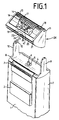
- Fig. 1 is the upper part of a dry shaver, the housing with 1, the on and off switch with 2, the long hair trimmer with 3, the top of the housing with 4, which from the opening 5 in the Housing top 4 protruding drive pin with 6, the extending arm of the housing narrow sides 7 and 8 pivot arms with 9 and 10 and the shaving head 12 is pivotally mounted by means of bearing pins 11 in the bearing arms provided in the pivot arms with SK.
- the shaving head SK shows a pair of shaving heads 14 and 15 running parallel to one another, which are formed by two lower knives 16 and 17 and by shaving foil 18 which is curved around these lower knives.
- the lower cutters 16 and 17 are resiliently mounted on a common coupling element 19 - see FIG. 2.
- the coupling element 19 is coupled to a drive element 47, which is part of a swing bridge mounted in the shaving head frame 21 - see FIGS. 2 and 3.
- the latter is provided with two transverse ribs 22 and 23, in the intermediate space 24 of which the drive pin 6 engages.
- the transverse ribs 22 and 23 of the swing bridge oscillate within the opening 26 provided in the base plate 25 of the shaving head frame 21 when the drive is switched on.
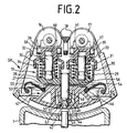
- FIG. 2 shows a cross section through the pivotably mounted shaving head SK according to FIG. 1.
- the two lower knives 16, 17 each rest against a shaving foil 18 which is arched in the shaving head frame 21 and which can also be formed in one piece.
- the coupling element 19 consists of a base plate 27 with two molded-on, pot-like containers 28, 29 and the container covers 30, 31 surrounding them in a pot-like manner and the guide bolts 32, 33 arranged inside the containers 28, 29 and the container covers 30, 31, including those surrounding them Compression springs 34, 35.
- the guide pin 32 is fastened in the container 28 and the guide pin 33 in the container 29.
- a sliding bore 40, 41 for the respective guide pin 32, 33 is formed in the respective container lid 30, 31.
- the container covers 30, 31 are coupled to the containers 28, 29 by means of a clip connection which enables the vertical up and down movement of the container lids 30, 31 - see FIG. 3.
- the lower knives 16, 17 are each pivotably articulated by means of a coupling piece 36, 37 and articulated bolts 38, 39 arranged transversely to the longitudinal extent of the lower knives 16, 17 at the respective upper ends of the container lids 30, 31 - see FIGS. 2 and 3.
- a bearing bolt 42 is fastened in the center to the two guide bolts 32, 33 and extends from the base plate 27 in the direction of the housing 1.
- the bearing bolt 42 facing away from the base plate 27, the latter is provided with a circumferential, prismatic groove 43, the inclined surfaces 44, 45 of which have a different slope, the inclined surface 45 extending to the end of the bearing bolt 42 being provided with a smaller slope than the opposite one Sloping surface 44.
- the bearing pin 42 extends through a bearing bore 48 provided in the cover plate 46 of the drive element 47.
- two spring elements 49, 50 in the form of spring struts with molded-on locking cams 51, 52 are formed on the side of the cover plate 46 facing the housing 1.
- interlocking elements 53 to 56 which can be brought into engagement, are respectively molded or formed on the cover plate 46 and on the base plate 27.
- These form-locking elements preferably consist of prismatic projections 53, 54 which engage in appropriately shaped prismatic grooves 55, 56.
- the interlocking form-locking elements 53 to 56 serve for a defined orientation of the lower knives 16 and 17 which are resiliently arranged on the coupling element 19 in the direction of vibration.
- four interlocking form-fitting elements 53 to 60 are arranged on the coupling element 19 and on the drive element 47 in such a way that the common central axis M of bearing bolts 42 and bearing bore 48 through the intersection which extends at right angles intersecting directions of extension of the form-locking elements 53 to 60.
- the engaged form-locking elements are mutually interchangeable with spring elements 49 resting on the inclined surface 45 via the latching cams 51, 52. 50 feasible.
- Such a change for example a rotation of the coupling element by 90 °, brings about a corresponding adjustment of the lower knives 16, 17 with respect to their direction of oscillation and enables easy cleaning of the lower knives 16, 17 in the state coupled to the drive element 47 and of the interior of the shaving head frame 21 with the shaving foil removed 18.
- the drive element 47 according to FIG. 2 is part of an oscillating bridge arranged in the pivotably mounted shaving head SK - see FIG. 1, which is described in more detail with reference to FIG. 3.
- FIG. 3 corresponding to FIG. 1, the housing with 1, the swivel arms integrally formed on the housing with 9 and 10, the protruding from the opening 5 in the upper side 4 of the housing, into the intermediate space 24 of the transverse ribs 22 provided on the swing bridge designated with 61 , 23 protruding drive pin designated 6.
- the bottom plate 27 closing the shaving head frame 21 is U-shaped.
- the legs 66, 67 of the base plate 27 extend parallel to the end walls 62, 63 of the shaving head frame.
- the swing bridge 61 consisting of two hanging spring arms 68, 69 and a plate 70 connecting the spring arms 68, 69 is fastened.
- the base plate 27 has an opening 26 into which the transverse ribs 22, 23 of the swing bridge 61 protrude for the purpose of coupling with the drive pin 6.
- the drive element 47 serving for coupling with the coupling element 19 is molded into the base plate 70 and is therefore part of the swing bridge 61.
- the positive locking elements 57 to 60 are in engagement due to the coupled state of the coupling element 19 and the drive element 47.
- the seal 71 is on the one hand on the drive element 47 and on the other hand attached to the inner wall 64 of the shaving head frame.
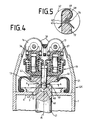
- the shaving head SK is arranged immovably on the housing 1 of the dry shaving apparatus.
- the structural design of the coupling element 19 and the lower knives 16 and 17 articulated by means of the coupling pieces 36, 37 corresponds to the design described in detail in FIG. 2.
- the end of the oscillatingly driven drive element 47 which is used for coupling to the coupling element 19, projects through the opening 5 provided in the upper side 4 of the housing into the interior of the shaving head SK.
- the drive element 47 consists of a drive pin with a bearing bore 48 arranged on its center axis M in the form of a blind hole and a groove 73 recessed on the outside in the bearing bore wall 72 for receiving a spring element 49.
- the course of the groove 73 in the bearing bore wall 72 is designed such that this partially intersects the interior of the bearing bore 48, as is illustrated in more detail by the section AA in FIG. 4 in FIG. 5 with the reference numerals from FIG. 4.
- the spring element 49 consists of a substantially U-shaped bow with a curved part 74 curved toward the bearing bore 48 for the purpose of partial engagement in the bearing bore 48.
- the distance of the groove 73 from the cover plate 46 of the drive element 47 is such that at one in engagement with the bearing bore 48 of the bearing bolt 42 of the coupling element 19, the spring element 49 comes into contact with the inclined surface 45 of the prismatic groove 43 provided on the bearing bolt 42, in order to couple and securely engage the coupling element 19 by means of the spring action emanating from the spring element 49 and drive element 47 to accomplish.
- the coupling element 19 with the lower knives 16 and 17 resiliently mounted on the latter can be easily removed from the drive element 47 against the spring pressure of the spring element 49.
- the bearing pin 42 is tapered at the end in order to simplify its insertion into the bearing bore and also to facilitate the expansion of the spring element 49 when it is plugged together.
Abstract
Description
Die Erfindung bezieht sich auf einen Trockenrasierapparat mit einem Paar von parallel zueinander verlaufenden, länglichen Scherköpfen, deren Untermesser auf einem gemeinsamen Kupplungselement federnd angeordnet sind, wobei das Kupplungselement mit dem Antriebselement des elektrischen Antriebes lösbar gekoppelt ist.The invention relates to a dry shaving apparatus with a pair of parallel, elongated shaving heads, the lower knives of which are resiliently arranged on a common coupling element, the coupling element being detachably coupled to the drive element of the electric drive.
Ein Trockenrasierapparat der eingangs genannten Art ist aus dem JP-U 57-135 365 bekannt. Wie aus den Figuren 2 und 3 dieser Druckschrift ersichtlich, besteht der Antrieb für die beiden parallel zueinander verlaufenden Untermesser aus einem einzigen Bauteil, und zwar einer Schwingbrücke, einem an der Schwingbrücke angeformten Kupplungselement und zwei an dem Kupplungselement angeformten Antriebsstiften, auf denen die Untermesser federnd gelagert und mittels einer Klippverbindung gehalten sind.A dry shaver of the type mentioned is known from JP-U 57-135 365. As can be seen from Figures 2 and 3 of this document, the drive for the two parallel lower knives consists of a single component, namely a swing bridge, a coupling element formed on the swing bridge and two drive pins formed on the coupling element, on which the lower knives are resilient stored and held by means of a clip connection.
Aus der DE-OS 26 24 601 ist ein Trockenrasierappart mit parallel zueinander verlaufenden Scherköpfen bekannt, deren Untermesser auf einem gemeinsamen Kupplungselement aufsteckbar angeordnet sind. Das Kupplungselement ist auf dem Antriebselement federnd gelagert und mit diesem über einen Schwenkverschluß gekoppelt. Diese Art der federnden Abstützung der Untermesser ermöglicht während der Rasur kein separates Einfedern der jeweiligen Untermesser in Abhängigkeit von den jeweiligen auf diese unterschiedlich einwirkenden Anpreßdrücken.From DE-OS 26 24 601 a dry shaving apparatus with shaving heads running parallel to one another is known, the lower knives of which are arranged on a common coupling element. The coupling element is resiliently mounted on the drive element and coupled to it via a swivel lock. This type of resilient support of the lower knives does not allow the respective lower knives to deflect separately during shaving, depending on the respective contact pressures acting differently on them.
Aufgabe der Erfindung ist es, einen Trockenrasierapparat der eingangs genannten Art so zu schaffen, daß dessen Untermesser gemeinsam mit einem Antriebsorgan des Trockenrasierapparates sicher und einfach handhabbar, koppelbar sowie entkoppelbar sind, und zwar unter Beibehaltung der jedem Untermesser zugeordneten, federnden Abstützung und Anlage an dem bzw. den Obermessern.ISABELLEThe object of the invention is to provide a dry shaver of the type mentioned in such a way that its lower blades, together with a drive element of the dry shaver, are safe and easy to handle, can be coupled and uncoupled, while maintaining the resilient support and system associated with each lower blade or the upper knives.ISABELLE
Nach der Erfindung wird diese Aufgabe bei einem Gerät der eingangs genannten Art dadurch gelöst, daß das Kupplungselement mittels eines in eine Lagerbohrung an einem Antriebselement eingreifenden Lagerbolzens mit dem Antriebselement gekoppelt ist, daß das Kupplungselement mittels wenigstens einem in eine am Lagerbolzen vorgesehene, zwei Schrägflächen aufweisende, prismatische Nut einrastenden Federelement in Anlage an dem Antriebselement gehalten ist, daß das Federelement in der verriegelten Stellung federnd an einer der Schrägflächen anliegt, und daß die aus Federelement und prismatischer Nut bestehende Verriegelung mittels einer der an dem Federelement anliegenden Schrägfläche der prismatischen Nut gegen den Druck des Federelementes entriegelbar ist.According to the invention, this object is achieved in a device of the type mentioned above in that the coupling element is coupled to the drive element by means of a bearing bolt engaging in a bearing bore on a drive element, that the coupling element has at least one inclined surface in a bearing bolt provided on the bearing pin , prismatic groove engaging spring element is held in contact with the drive element, that the spring element rests resiliently on one of the inclined surfaces in the locked position, and that the locking element consisting of the spring element and prismatic groove is locked by means of one of the inclined surface of the prismatic groove against the spring element Pressure of the spring element is unlockable.
Ein besonderer Vorteil dieser handhabungsgerechten Koppelung der beiden Untermesser über ein gemeinsames Kupplungselement - und somit unter Beibehaltung der jedem Untermesser zugeordneten, federnden Abstützung und Anlage an dem bzw. den Obermessern - mit einem Antriebselement des elektrischen Antriebes besteht darin, diese Koppelungsverbindung sowohl für Trockenrasierapparate mit einem schwenkbar gelagerten Scherkopf (Fig. 1, 2 und 3) als auch für einen Trockenrasierapparat mit einem auf dem Gehäuse zwar abnehmbar, ansonsten jedoch unbewegbar angeordneten Scherkopf einsetzbar ist. Die Koppelungsverbindung ermöglicht ein leichtes Abnehmen der aus den beiden Untermessern und dem Kupplungselement bestehenden Baueinheit sowohl zum Zwecke des Austausches nach Abnutzung der Untermesser als auch zum Zwecke einer besseren Reinigung dieser Baueinheit, einschließlich des jeweiligen Scherkopfrahmens.A particular advantage of this handling-friendly coupling of the two lower knives via a common coupling element - and thus while maintaining the resilient support and contact associated with each lower knife with the upper knife (s) - with a drive element of the electric drive is that this coupling connection for dry shavers with one pivotably mounted shaving head (Fig. 1, 2 and 3) as well as for a dry shaver with a removable on the housing, but otherwise immovably arranged shaving head can be used. The coupling connection enables easy removal of the structural unit consisting of the two lower knives and the coupling element both for the purpose of replacement after the lower knives have worn out and for the purpose of better cleaning of this structural unit, including the respective shaving head frame.
Eine toleranzunabhängige und sichere Anlage des Kupplungselementes an dem Antriebselement ist dadurch gewährleistet, daß die Schrägflächen der prismatischen Nut am Lagerbolzen mit einer unterschiedlichen Steigung versehen sind und die Schrägfläche geringerer Steigung im gekoppelten Zustand von Kupplungselement und Antriebselement von dem Federelement beaufschlagt ist.A tolerance-independent and secure contact of the coupling element with the drive element is ensured in that the inclined surfaces of the prismatic groove on the bearing bolt are provided with a different pitch and the inclined surface with a smaller pitch is acted upon by the spring element in the coupled state of the coupling element and the drive element.
Eine besonders vorteilhafte Ausführungsform der Erfindung zeichnet sich dadurch aus, daß die Lagerbohrung in einen im Antriebselement vorgesehenen Hohlraum einmündet und daß als Federelement wenigstens ein in den Hohlraum hineinragender Federarm in Verlängerung der Lagerbohrung am Antriebselement angeformt ist.A particularly advantageous embodiment of the invention is characterized in that the bearing bore opens into a cavity provided in the drive element and that at least one spring arm protruding into the cavity is formed on the drive element as an extension of the bearing bore.
In weiterer Ausgestaltung dieser Ausführungsform ist das Antriebselement Bestandteil einer im Scherkopfrahmen des Trockenrasierapparates angeordneten Schwingbrücke. Nach einer weiteren Ausführungsform ist das Antriebselement Bestandteil einer im Gehäuse des Trockenrasierapparates angeordneten Schwingbrücke.In a further embodiment of this embodiment, the drive element is part of a swing bridge arranged in the shaving head frame of the dry shaving apparatus. According to a further embodiment, the drive element is part of a swing bridge arranged in the housing of the dry shaving apparatus.
Nach einer anderen vorteilhaften Ausführungsform der Erfindung besteht das Antriebselement aus einem oszillierenden Antriebsstift mit einer auf dessen Mittenachse angeordneten Lagerbohrung und einer in der Lagerbohrungswandung außenseitig eingelassenen Nut zur Aufnahme des Federelementes, wobei die Nut den Innenraum der Lagerbohrung partiell schneidet. In weiterer Ausgestaltung dieser Ausführungsform besteht das Federelement aus einem der Form der Nut angepaßten, den Inneraum der Lagerbohrung partiell durchsetzenden Federbügel.According to another advantageous embodiment of the invention, the drive element consists of an oscillating drive pin with a bearing bore arranged on its center axis and a groove recessed on the outside in the bearing bore wall for receiving the spring element, the groove partially cutting the interior of the bearing bore. In a further embodiment of this embodiment, the spring element consists of a spring clip adapted to the shape of the groove and partially penetrating the interior of the bearing bore.
In weiterer Ausgestaltung der Erfindung sind am Kupplungselement und an dem Antriebselement in Eingriff bringbare, die Ausrichtung der Untermesser bestimmenden Formschlußelemente angeordnet. Zweckmäßigerweise sind bei einer derartigen Ausführungsform am Kupplungselement und am Antriebselement jeweils zwei parallel zur Schwingbewegung der Untermesser verlaufende Formschlußelemente angeordnet, um eine Ausrichtung der beiden Untermesser in Schwingungsrichtung zu bewerkstelligen. Um die Reinigung des Scherkopfrahmens sowie der beiden Untennesser in mit dem Antrieb gekoppelten Zustand zu ermöglichen, sind nach einer weiteren Ausführungsform der Erfindung am Kupplungselement und am Antriebselement jeweils vier Formschlußelemente derart angeordnet, daß die gemeinsame Mittenachse von Lagerbohrung und Lagerbolzen durch den Schnittpunkt der sich rechtwinklig schneidenden Erstreckungsrichtungen der Formschlußelemente verläuft. Vorzugsweise ist die Erstreckung der Schrägfläche auf die Erstreckung der Formschlußelemente derart abgestimmt, daß ein Wechsel der im Eingriff befindlichen Formschlußelemente untereinander bei an der Schrägfläche anliegendem Federelement gewährleistet ist. Zweckmäßigerweise sind die Formschlußelemente aus Nuten und Erhebungen prismatischer Formgebung gebildet.In a further embodiment of the invention, form-locking elements which can be brought into engagement and which determine the orientation of the lower knives are arranged on the coupling element and on the drive element. In such an embodiment, two form-locking elements running parallel to the oscillating movement of the lower blades are expediently arranged on the coupling element and on the drive element in order to bring about an alignment of the two lower blades in the direction of vibration. In order to enable the cleaning of the shaving head frame and of the two bottom units in the state coupled to the drive, according to a further embodiment of the invention, the coupling element and the drive element are each four interlocking elements arranged in such a way that the common center axis of the bearing bore and the bearing pin runs through the intersection of the perpendicularly intersecting directions of extension of the interlocking elements. The extension of the inclined surface is preferably matched to the extension of the form-fitting elements in such a way that a change of the form-fitting elements in engagement with one another is ensured with the spring element lying against the inclined surface. The interlocking elements are expediently formed from grooves and elevations of prismatic shape.
In der nachfolgenden Beschreibung und den Zeichnungen sind Ausführungsbeispiele der Erfindung dargestellt, und zwar zeigen:
- Fig. 1
- einen Teil eines Trockenrasierapparates mit abgenommenem Scherkopf in Perspektive;
- Fig. 2
- einen Querschnitt durch einen schwenkbar gelagerten Scherkopf und den oberen Teil des Trockenrasierergehäuses;
- Fig. 3
- einen Längsschnitt durch einen am Gehäuse des Trockenrasierapparates schwenkbar gelagerten Scherkopf;
- Fig. 4
- einen Querschnitt durch einen auf dem Gehäuse des Trockenrasierapparates angeordneten Scherkopfrahmen;
- Fig. 5
- einen Schnitt A-A nach Fig. 4 durch ein Antriebselement mit Federlement.
- Fig. 1
- a part of a dry shaver with the shaving head removed in perspective;
- Fig. 2
- a cross section through a pivotally mounted shaving head and the upper part of the dry shaver housing;
- Fig. 3
- a longitudinal section through a shaving head pivotally mounted on the housing of the dry shaving apparatus;
- Fig. 4
- a cross section through a shaving head frame arranged on the housing of the dry shaving apparatus;
- Fig. 5
- a section AA of FIG. 4 by a drive element with spring element.
In Fig. 1 ist der obere Teil eines Trockenrasierers, dessen Gehäuse mit 1, der Ein- und Ausschalter mit 2, der Langhaarschneider mit 3, die Gehäuseoberseite mit 4, der aus der Öffnung 5 in der Gehäuseoberseite 4 herausragende Antriebsstift mit 6, die in Verlängerung der Gehäuseschmalseiten 7 und 8 verlaufenden Schwenkarme mit 9 und 10 und der mittels Lagerzapfen 11 in in den Schwenkarmen vorgesehenen Lagerbohrungen 12 schwenkbar gelagerte Scherkopf mit SK bezeichnet ist.In Fig. 1 is the upper part of a dry shaver, the housing with 1, the on and off switch with 2, the long hair trimmer with 3, the top of the housing with 4, which from the opening 5 in the
Der Scherkopf SK zeigt ein Paar von parallel zueinander verlaufenden Scherköpfen 14 und 15, die durch zwei Untermesser 16 und 17 sowie durch diese Untermesser gewölbt umgebende Scherfolie 18 gebildet sind. Die Untermesser 16 und 17 sind auf einem gemeinsamen Kupplungselement 19 federnd - siehe Fig. 2 - gelagert. Das Kupplungselement 19 ist mit einem Antriebselement 47, das Bestandteil einer im Scherkopfrahmen 21 gelagerten Schwingbrücke - siehe Fig. 2 und 3 - ist, gekoppelt. Zwecks Übertragung der Antriebsbewegung vom Antriebsstift 6 auf die Schwingbrücke ist diese mit zwei Querrippen 22 und 23 versehen, in deren Zwischenraum 24 der Antriebsstift 6 eingreift. Die Querrippen 22 und 23 der Schwingbrücke oszillieren bei eingeschaltetem Antrieb innerhalb der in der Bodenplatte 25 des Scherkopfrahmens 21 vorgesehenen Öffnung 26.The shaving head SK shows a pair of shaving
Fig. 2 zeigt einen Querschnitt durch den schwenkbar gelagerten Scherkopf SK nach Fig. 1. Die beiden Untermesser 16, 17 liegen jeweils an einer im Scherkopfrahmen 21 gewölbt eingespannten Scherfolie 18, die auch einteilig ausgebildet sein kann, an. Das Kupplungselement 19 besteht aus einer Bodenplatte 27 mit zwei angeformten, topfartigen Behältern 28, 29 und diese topfartig umgebenden Behälterdeckeln 30, 31 sowie den innerhalb der Behälter 28, 29 und den Behälterdeckeln 30, 31 jeweils angeordneten Führungsbolzen 32, 33, einschließlich der diese umgebenden Druckfedern 34, 35. Der Führungsbolzen 32 ist in dem Behälter 28 und der Führungsbolzen 33 in dem Behälter 29 befestigt. Um eine vertikale Führung der jeweils mit den Behälterdeckeln 30, 31 gekoppelten Untermesser 16, 17 gegen den Druck der jeweiligen Druckfeder 34, 35 zu gewährleisten, ist in dem jeweiligen Behälterdeckel 30, 31 eine Gleitbohrung 40, 41 für den jeweiligen Führungsbolzen 32, 33 eingeformt. Mittels einer die vertikale Auf- und Abbewegung der Behälterdeckel 30, 31 ermöglichenden Klippverbindung - siehe Fig. 3 - sind die Behälterdeckel 30, 31 mit den Behältern 28, 29 gekoppelt. Die Untermesser 16, 17 sind jeweils mittels eines Kupplungsstückes 36, 37 und quer zur Längserstreckung der Untermesser 16, 17 angeordneten Gelenkbolzen 38, 39 an den jeweiligen oberen Enden der Behälterdeckel 30, 31 schwenkbar angelenkt - siehe Fig. 2 und 3.FIG. 2 shows a cross section through the pivotably mounted shaving head SK according to FIG. 1. The two
In der Bodenplatte 27 des Kupplungselementes 19 ist mittig zu den beiden Führungsbolzen 32, 33 ein Lagerbolzen 42 befestigt, der aus der Bodenplatte 27 herausragend sich in Richtung des Gehäuses 1 erstreckt. An dem der Bodenplatte 27 abgewandten Ende des Lagerbolzens 42 ist dieser mit einer umlaufenden, prismatischen Nut 43 versehen, deren Schrägflächen 44, 45 eine unterschiedliche Steigung aufweisen, wobei die zum Ende des Lagerbolzens 42 verlaufende Schrägfläche 45 mit einer geringeren Steigung versehen ist als die entgegengesetzte Schrägfläche 44.In the
Der Lagerbolzen 42 durchragt eine in der Deckplatte 46 des Antriebselementes 47 vorgesehene Lagerbohrung 48. In Verlängerung der Lagerbohrung 48 sind an der dem Gehäuse 1 zugewandten Seite der Deckplatte 46 zwei Federelemente 49, 50 in Form von Federbeinen mit angeformten Rastnocken 51, 52 angeformt. Durch Anlage der Rastnocken 51, 52 der Federelemente 49, 50 an der Schrägfläche 45 des Lagerbolzens 42 ist eine bewegungsfreie Anlage der Bodenplatte 27 des Kupplungselementes 19 an der Deckplatte 46 des Antriebselementes 47 gewährleistet, da die auf die Schrägfläche 45 einwirkende, aus der Federkraft der Federelemente 49, 50 resultierende Kraft das Kupplungselement 19 zum Antriebselement 47 zieht.The
Um einerseits die Anlage von Kupplungselement 19 und Antriebselement 47 weiter zu verbessern, sind an der Deckplatte 46 und an der Bodenplatte 27 jeweils wenigstens zwei in Eingriff bringbare Formschlußelemente 53 bis 56 an- bzw. eingeformt. Diese Formschlußelemente bestehen vorzugsweise aus prismatisch angeformten Erhebungen 53, 54, die in entsprechend geformte prismatische Nuten 55, 56 eingreifen. Zusätzlich zur optimierten Anlage vom Kupplungselement 19 und Antriebselement 47 dienen die im Eingriff befindlichen Formschlußelemente 53 bis 56 einer definierten Ausrichtung der auf dem Kupplungselement 19 federnd angeordneten Untermesser 16 und 17 in Schwingungsrichtung.In order to further improve the contact of
Nach einer Ausführungsform, die sich aus der Darstellung nach Fig. 2 unter Einbeziehung der Darstellung nach Fig. 3 ergibt, sind am Kupplungselement 19 und am Antriebselement 47 jeweils vier in Eingriff befindliche Formschlußelemente 53 bis 60 derart angeordnet, daß die gemeinsame Mittenachse M von Lagerbolzen 42 und Lagerbohrung 48 durch den Schnittpunkt, der sich rechtwinklig schneidenden Erstreckungsrichtungen der Formschlußelemente 53 bis 60 verläuft. Bei einer auf die vertikale Erstreckung, das heißt die Höhe der Formschlußelemente 53, 54, 57, 58 angepaßten Erstreckungslänge der Schrägfläche 45, ist ein Wechsel der im Eingriff befindlichen Formschlußelemente untereinander bei an der Schrägfläche 45 über den Rastnocken 51, 52 anliegenden Federelementen 49, 50 durchführbar. Ein derartiger Wechsel, zum Beispiel eine Verdrehung des Kupplungselementes um 90°, bewirkt eine entsprechende Ouerstellung der Untermesser 16, 17 in Bezug auf deren Schwingungsrichtung und ermöglicht eine leichte Reinigung der Untermesser 16, 17 im mit dem Antriebselement 47 gekoppelten Zustand sowie des Innenraumes des Scherkopfrahmens 21 bei abgenommener Scherfolie 18.According to one embodiment, which results from the representation according to FIG. 2 including the representation according to FIG. 3, four interlocking form-
Das Antriebselement 47 nach Fig. 2 ist Bestandteil einer in dem schwenkbar gelagerten Scherkopf SK - siehe Fig. 1 - oszillierend angeordneten Schwingbrücke, die anhand von Fig. 3 näher beschrieben wird.The
In Fig. 3 ist entsprechend der Fig. 1 das Gehäuse mit 1, die am Gehäuse angeformten Schwenkarme mit 9 und 10, der aus der Öffnung 5 in der Gehäuseoberseite 4 herausragende, in den Zwischenraum 24 der an der mit 61 bezeichneten Schwingbrücke vorgesehenen Querrippen 22, 23 hineinragende Antriebsstift mit 6 bezeichnet. Der Scherkopfrahmen 21, von dem in Fig. 3 die Stirnseitenwände 62, 63 und die in den Innenraum hineinragende Innenwand 64 ersichtlich sind, ist mittels einer nicht näher dargestellten Gelenkverbindung bei G, G₁ an den Schwenkarmen 9 und 10 schwenkbar gelagert. Die den Scherkopfrahmen 21 schließende Bodenplatte 27 ist U-förmig ausgebildet. Die Schenkel 66, 67 der Bodenplatte 27 erstrecken sich parallel zu den Stirnseitenwänden 62, 63 des Scherkopfrahmens. Auf den oberen Enden der Schenkel 66, 67 ist die aus zwei herabhängenden Federarmen 68, 69 und einer die Federarme 68, 69 verbindenden Platte 70 bestehende Schwingbrücke 61 befestigt. Die Bodenplatte 27 weist eine Öffnung 26 auf, in die die Querrippen 22, 23 der Schwingbrücke 61 zwecks Koppelung mit dem Antriebsstift 6 hineinragen. Das der Koppelung mit dem Kupplungselement 19 dienende Antriebselement 47 ist in die Bodenplatte 70 eingeformt und somit Bestandteil der Schwingbrücke 61. Die Formschlußelemente 57 bis 60 befinden sich in Eingriff aufgrund des gekoppelten Zustandes vom Kupplungselement 19 und Antriebselement 47. Die Dichtung 71 ist einerseits am Antriebselement 47 und andererseits an der Innenwand 64 des Scherkopfrahmens befestigt.In FIG. 3, corresponding to FIG. 1, the housing with 1, the swivel arms integrally formed on the housing with 9 and 10, the protruding from the
Bei der Ausführungsform nach Fig. 4 ist der Scherkopf SK unbeweglich auf dem Gehäuse 1 des Trockenrasierapparates angeordnet. Die konstruktive Ausgestaltung des Kupplungselementes 19 sowie der mittels der Kupplungsstücke 36, 37 angelenkten Untermesser 16 und 17 entspricht der unter Fig. 2 im einzelnen beschriebenen Ausgestaltung. Das oszillierend angetriebene Antriebselement 47 ragt mit seinem der Koppelung mit dem Kupplungselement 19 dienenden Ende durch die in der Gehäuseoberseite 4 vorgesehene Öffnung 5 in den Innenraum des Scherkopfes SK hinein. Das Antriebselement 47 besteht aus einem Antriebsstift mit einer auf dessen Mittenachse M angeordneten Lagerbohrung 48 in Form einer Sacklochbohrung und einer in der Lagerbohrungswandung 72 außenseitig eingelassenen Nut 73 zwecks Aufnahme eines Federelementes 49. Der Verlauf der Nut 73 in der Lagerbohrungswandung 72 ist derart gestaltet, daß diese den Innenraum der Lagerbohrung 48 partiell schneidet, wie dies durch den in Fig. 4 angegebenen Schnitt A-A in Fig. 5 unter Angabe der Bezugszeichen aus Fig. 4 näher veranschaulicht ist. Das Federelement 49 besteht bei dieser Ausführungsform aus einem im wesentlichen U-förmig gebogenen Bügel mit einem zur Lagerbohrung 48 gekrümmten Bogenteil 74 zwecks partiellen Eingriff in die Lagerbohrung 48. Der Abstand der Nut 73 zur Deckplatte 46 des Antriebselementes 47 ist derart bemessen, daß bei einem in Eingriff mit der Lagerbohrung 48 befindlichen Lagerbolzen 42 des Kupplungselementes 19 das Federelement 49 zur Anlage an die Schrägfläche 45 der am Lagerbolzen 42 vorgesehenen, prismatisch ausgebildeten Nut 43 gelangt, um mittels der von dem Federelement 49 ausgehenden Federwirkung die Koppelung und sichere Anlage vom Kupplungselement 19 und Antriebselement 47 zu bewerkstelligen. Nach Abnahme des Scherkopfrahmens 21 t der in diesem eingespannten Scherfolie 18 vom Gehäuse 1 kann Kupplungselement 19 mit den auf diesen federnd gelagerten Untermesern 16 und 17 gegen den Federdruck des Federelementes 49 leicht vom Antriebselement 47 abgezogen werden. Der Lagerbolzen 42 ist endseitig kegelförmig ausgebildet, um dessen Einführung in die Lagerbohrung zu vereinfachen und darüber hinaus das Aufweiten des Federelementes 49 beim Zusammenstecken zu erleichtern.In the embodiment according to FIG. 4, the shaving head SK is arranged immovably on the housing 1 of the dry shaving apparatus. The structural design of the
Claims (12)
- A dry shaving apparatus comprising a pair of parallel elongate shaving heads (14, 15) having their inner cutters (16, 17) resiliently mounted on a common coupling member (19) which is detachably coupled to the drive member (47) of the electric drive, characterized in that said coupling member (19) is coupled to said drive member (47) by means of a bearing pin (42) engaging in a bearing bore (48) provided in said drive member (47), that said coupling member (19) is held in abutting engagement with said drive member (47) by means of at least one spring element (49, 50) locking into a prismatic groove (43) having two beveled surfaces (44, 45) and provided on said bearing pin (42), that said spring element (49, 50) rests resiliently against one of said beveled surfaces (45) in the locked position, and that the locking device which is comprised of said spring element (49, 50) and said prismatic groove (43) is releasable from its locking engagement against the pressure of said spring element (49, 50) by means of said beveled surface (45) of said prismatic groove (43) against which said spring element (49, 50) rests.
- The dry shaving apparatus as claimed in claim 1, characterized in that said beveled surfaces (44, 45) of said prismatic groove (43) on said bearing pin (42) have different gradients, and that the beveled surface (45) with the smaller gradient is acted upon by said spring element (49, 50) in the coupled condition of said coupling member (19) and said drive member (47).
- The dry shaving apparatus as claimed in claim 1, characterized in that said bearing bore (48) terminates in a hollow space provided in said drive member (47), and that said spring element (49, 50) includes at least one spring arm which extends into said hollow space and is integrally formed on said drive member (47) in an extension of said bearing bore (48).
- The dry shaving apparatus as claimed in claim 3, characterized in that said drive member (47) is part of an oscillating bridge (61) arranged in the shaving head frame (21) of the dry shaving apparatus.
- The dry shaving apparatus as claimed in claim 3, characterized in that said drive member (47) is part of an oscillating bridge arranged in the casing (1) of the dry shaving apparatus.
- The dry shaving apparatus as claimed in claim 1, characterized in that said drive member (47) is comprised of an oscillating drive pin having a bearing bore (48) arranged on its center axis (M) and a groove (73) embedded in the outside of the bearing bore wall (72) for receiving said spring element (49), said groove (73) partially intersecting the space in the interior of said bearing bore (48).
- The dry shaving apparatus as claimed in claim 6, characterized in that said spring element (49) is a spring clip conformed to the contour of said groove (73) and partially extending into the space in the interior of said bearing bore (48).
- The dry shaving apparatus as claimed in claim 1, characterized in that positive-engagement means (53 to 56; 57 to 60) suitable for relative engagement and determining the alignment of said inner cutters (16, 17) are arranged on said coupling member (19) and on said drive member (47).
- The dry shaving apparatus as claimed in claim 8, characterized in that said coupling member (19) and said drive member (47) are each provided with two positive-engagement means (57, 58, 59, 60) extending parallel to the direction of oscillation of said inner cutters (16, 17).
- The dry shaving apparatus as claimed in claim 8, characterized in that said coupling member (19) and said drive member (47) are each provided with four positive-engagement means (53 to 60), such that the common center axis (M) of said bearing bore (48) and said bearing pin (42) extends through the point of intersection of the directions in which said positive-engagement means (53 to 60) extend, the directions intersecting at right angles.
- The dry shaving apparatus as claimed in any one of the claims 8 to 10, characterized in that the extent of said beveled surface (45) is adapted to the extent of said positive-engagement means (53 to 56; 57 to 60) such as to ensure interchangeability of said engaged positive-engagement means (53 to 56; 57 to 60) when said spring element (49, 50) rests against said beveled surface (45).
- The dry shaving apparatus as claimed in any one of the claims 8 to 11, characterized in that said positive-engagement means (53 to 60) are formed of grooves and elevations of a prismatic configuration.
Priority Applications (1)
| Application Number | Priority Date | Filing Date | Title |
|---|---|---|---|
| AT90910558T ATE95459T1 (en) | 1989-08-16 | 1990-07-21 | KNIFE BLOCK CLUTCH FOR DOUBLE HEAD RAZOR. |
Applications Claiming Priority (2)
| Application Number | Priority Date | Filing Date | Title |
|---|---|---|---|
| DE3926894A DE3926894C1 (en) | 1989-08-16 | 1989-08-16 | |
| DE3926894 | 1989-08-16 |
Publications (2)
| Publication Number | Publication Date |
|---|---|
| EP0487537A1 EP0487537A1 (en) | 1992-06-03 |
| EP0487537B1 true EP0487537B1 (en) | 1993-10-06 |
Family
ID=6387134
Family Applications (1)
| Application Number | Title | Priority Date | Filing Date |
|---|---|---|---|
| EP90910558A Expired - Lifetime EP0487537B1 (en) | 1989-08-16 | 1990-07-21 | Blade block coupling for twin-headed razors |
Country Status (5)
| Country | Link |
|---|---|
| US (1) | US5201781A (en) |
| EP (1) | EP0487537B1 (en) |
| JP (1) | JPH088946B2 (en) |
| DE (2) | DE3926894C1 (en) |
| WO (1) | WO1991002629A1 (en) |
Families Citing this family (17)
| Publication number | Priority date | Publication date | Assignee | Title |
|---|---|---|---|---|
| DE4128220C1 (en) * | 1991-08-26 | 1992-08-06 | Braun Ag, 6000 Frankfurt, De | |
| DE4128218C1 (en) * | 1991-08-26 | 1992-08-06 | Braun Ag, 6000 Frankfurt, De | |
| DE4128219A1 (en) * | 1991-08-26 | 1993-03-04 | Braun Ag | SHAVER |
| US5611145A (en) | 1991-12-20 | 1997-03-18 | Wetzel; Matthias | Dry-shaving apparatus |
| US5185926A (en) * | 1992-02-07 | 1993-02-16 | Remington Products, Inc. | Multiple foil and cutting blade assembly for electric dry shavers |
| DE4303972C1 (en) * | 1993-02-11 | 1993-10-14 | Braun Ag | Electric dry razor with pivoted cutting head - has cutting head frame supported by pivot screws fitting in metal bearing elements in opposing carrier arms |
| JPH0730972U (en) * | 1993-11-17 | 1995-06-13 | 三洋電機株式会社 | Reciprocating electric razor |
| JP3716353B2 (en) * | 1995-07-31 | 2005-11-16 | 九州日立マクセル株式会社 | Rotary electric razor |
| KR100543557B1 (en) * | 1997-10-30 | 2007-04-25 | 산요덴키가부시키가이샤 | Electric shaver |
| DE69924468T2 (en) * | 1998-01-20 | 2006-02-16 | Wheel Technology Ltd. | ELECTRIC RAZOR WITH ROLLER MOUNTED DIRECT CONTACT BLADES |
| JP3916509B2 (en) * | 2002-05-29 | 2007-05-16 | 株式会社泉精器製作所 | Electric razor |
| KR101329274B1 (en) | 2004-06-21 | 2013-11-14 | 코닌클리케 필립스 일렉트로닉스 엔.브이. | Hair cutting apparatus |
| JP4960863B2 (en) | 2004-06-21 | 2012-06-27 | コーニンクレッカ フィリップス エレクトロニクス エヌ ヴィ | Shaving equipment |
| DE102006010323A1 (en) * | 2006-03-07 | 2007-09-13 | Braun Gmbh | Dry shaver with swiveling shaving head |
| EP2404715B1 (en) * | 2010-07-10 | 2012-11-28 | Braun GmbH | Electrically operated shaver with replaceable cutting device |
| EP2875919A1 (en) * | 2013-11-22 | 2015-05-27 | Koninklijke Philips N.V. | Hair cutting appliance, receptacle and connector plug |
| EP3300850B1 (en) * | 2016-09-28 | 2019-10-23 | Braun GmbH | Electrically-driven razor |
Family Cites Families (13)
| Publication number | Priority date | Publication date | Assignee | Title |
|---|---|---|---|---|
| US3044168A (en) * | 1960-01-05 | 1962-07-17 | Schick Inc | Spring holding means for electric shaver shearing head |
| CH453947A (en) * | 1966-07-29 | 1968-03-31 | Kobler & Co | Multi-part shaving head for dry shaver |
| US3858314A (en) * | 1973-06-20 | 1975-01-07 | Schick Inc | Drive assembly for an electric shaver |
| US3931675A (en) * | 1974-06-12 | 1976-01-13 | Sperry Rand Corporation | Electric dry shaver with releasable cutter head |
| US4001933A (en) * | 1975-06-04 | 1977-01-11 | Sperry Rand Corporation | Cutter drive arrangement for an electric dry shaver |
| US4219930A (en) * | 1978-07-07 | 1980-09-02 | Remington Products, Inc. | Cutter head assembly for an electric dry shaver |
| US4292737A (en) * | 1978-12-11 | 1981-10-06 | The Gillette Company | Dry shaver with differentially biased inner cutter and base members |
| US4233733A (en) * | 1979-01-02 | 1980-11-18 | Sunbeam Corporation | Electric shaver |
| JPS57135365A (en) * | 1981-02-16 | 1982-08-20 | Toshiba Corp | Watthour meter |
| JPS57135365U (en) * | 1981-02-19 | 1982-08-24 | ||
| US4700476A (en) * | 1984-11-02 | 1987-10-20 | Remington Products, Inc. | Shaver for a medical treatment preparation procedure |
| DE3610736A1 (en) * | 1986-03-29 | 1987-10-01 | Braun Ag | ELECTRIC SHAVER WITH A PIVOTING SHEAR HEAD SYSTEM |
| US4805300A (en) * | 1986-09-17 | 1989-02-21 | Remington Products, Inc. | Electric dry shaver having an improved drive arrangement |
-
1989
- 1989-08-16 DE DE3926894A patent/DE3926894C1/de not_active Expired - Fee Related
-
1990
- 1990-07-21 WO PCT/DE1990/000550 patent/WO1991002629A1/en active IP Right Grant
- 1990-07-21 EP EP90910558A patent/EP0487537B1/en not_active Expired - Lifetime
- 1990-07-21 JP JP2510246A patent/JPH088946B2/en not_active Expired - Lifetime
- 1990-07-21 DE DE90910558T patent/DE59003032D1/en not_active Expired - Fee Related
- 1990-07-21 US US07/829,068 patent/US5201781A/en not_active Expired - Lifetime
Also Published As
| Publication number | Publication date |
|---|---|
| DE3926894C1 (en) | 1990-12-06 |
| JPH088946B2 (en) | 1996-01-31 |
| DE59003032D1 (en) | 1993-11-11 |
| WO1991002629A1 (en) | 1991-03-07 |
| EP0487537A1 (en) | 1992-06-03 |
| US5201781A (en) | 1993-04-13 |
| JPH05500313A (en) | 1993-01-28 |
Similar Documents
| Publication | Publication Date | Title |
|---|---|---|
| EP0487537B1 (en) | Blade block coupling for twin-headed razors | |
| EP0603617B1 (en) | Dry shaver with a pivotable long hair cutter | |
| DE3610736C2 (en) | ||
| DE3721243C2 (en) | ||
| EP0387490B1 (en) | Double pivoting head razor | |
| EP0693988B1 (en) | Shaving head for electric razors | |
| WO2000006348A1 (en) | Electric dry razor | |
| DE3814554A1 (en) | CUTTING KNIFE | |
| WO2005002806A1 (en) | Electrical hair cutting appliance | |
| EP0532904B1 (en) | Dry shaver | |
| DE202013002343U9 (en) | Mechanical razor of simplified design | |
| DE4132844C2 (en) | Cutting head assembly for hair trimmers | |
| DE4128219C2 (en) | ||
| EP0673728B1 (en) | Dry shaver with shear foil frame lock | |
| US4604802A (en) | Squeegee blade trimmer | |
| DE19632333C1 (en) | Dry shaver with stop element arrangement | |
| EP0478704B1 (en) | Articulated frame for an electric razor | |
| EP1098740B1 (en) | Electric razor | |
| EP0529406B1 (en) | Dry shaver | |
| EP1098739B1 (en) | Electric razor | |
| DE1553814C3 (en) | Electric dry shaver | |
| EP0476326B1 (en) | Changeable frame for a dry shaver | |
| EP0474798B1 (en) | Articulated frame for a dry razor | |
| DE3428487A1 (en) | LONG HAIR CUTTER FOR DRY SHAVERS | |
| DE3338173A1 (en) | CUTTING DEVICE FOR CUTTING DOWN THE CONNECTING WIRE ENDS protruding from a printed circuit board from components |
Legal Events
| Date | Code | Title | Description |
|---|---|---|---|
| PUAI | Public reference made under article 153(3) epc to a published international application that has entered the european phase |
Free format text: ORIGINAL CODE: 0009012 |
|
| 17P | Request for examination filed |
Effective date: 19920118 |
|
| AK | Designated contracting states |
Kind code of ref document: A1 Designated state(s): AT BE CH DE DK ES FR GB IT LI LU NL SE |
|
| 17Q | First examination report despatched |
Effective date: 19930223 |
|
| GRAA | (expected) grant |
Free format text: ORIGINAL CODE: 0009210 |
|
| AK | Designated contracting states |
Kind code of ref document: B1 Designated state(s): AT BE CH DE DK ES FR GB IT LI LU NL SE |
|
| PG25 | Lapsed in a contracting state [announced via postgrant information from national office to epo] |
Ref country code: IT Free format text: LAPSE BECAUSE OF FAILURE TO SUBMIT A TRANSLATION OF THE DESCRIPTION OR TO PAY THE FEE WITHIN THE PRE;WARNING: LAPSES OF ITALIAN PATENTS WITH EFFECTIVE DATE BEFORE 2007 MAY HAVE OCCURRED AT ANY TIME BEFORE 2007. THE CORRECT EFFECTIVE DATE MAY BE DIFFERENT FROM THE ONE RECORDED.SCRIBED TIME-LIMIT Effective date: 19931006 Ref country code: SE Effective date: 19931006 Ref country code: DK Effective date: 19931006 Ref country code: ES Free format text: THE PATENT HAS BEEN ANNULLED BY A DECISION OF A NATIONAL AUTHORITY Effective date: 19931006 |
|
| REF | Corresponds to: |
Ref document number: 95459 Country of ref document: AT Date of ref document: 19931015 Kind code of ref document: T |
|
| REF | Corresponds to: |
Ref document number: 59003032 Country of ref document: DE Date of ref document: 19931111 |
|
| GBT | Gb: translation of ep patent filed (gb section 77(6)(a)/1977) |
Effective date: 19931021 |
|
| ET | Fr: translation filed | ||
| PG25 | Lapsed in a contracting state [announced via postgrant information from national office to epo] |
Ref country code: LU Free format text: LAPSE BECAUSE OF NON-PAYMENT OF DUE FEES Effective date: 19940731 |
|
| PLBE | No opposition filed within time limit |
Free format text: ORIGINAL CODE: 0009261 |
|
| STAA | Information on the status of an ep patent application or granted ep patent |
Free format text: STATUS: NO OPPOSITION FILED WITHIN TIME LIMIT |
|
| 26N | No opposition filed | ||
| REG | Reference to a national code |
Ref country code: FR Ref legal event code: CA Ref country code: FR Ref legal event code: CD |
|
| REG | Reference to a national code |
Ref country code: CH Ref legal event code: PFA Free format text: BRAUN AKTIENGESELLSCHAFT TRANSFER- BRAUN AKTIENGESELLSCHAFT;BRAUN GMBH Ref country code: CH Ref legal event code: NV Representative=s name: BOSSHARD & LUCHS PATENTANWAELTE;LUCHS & PARTNER PA |
|
| REG | Reference to a national code |
Ref country code: GB Ref legal event code: IF02 |
|
| PGFP | Annual fee paid to national office [announced via postgrant information from national office to epo] |
Ref country code: BE Payment date: 20030724 Year of fee payment: 14 |
|
| PGFP | Annual fee paid to national office [announced via postgrant information from national office to epo] |
Ref country code: CH Payment date: 20030731 Year of fee payment: 14 |
|
| PG25 | Lapsed in a contracting state [announced via postgrant information from national office to epo] |
Ref country code: LI Free format text: LAPSE BECAUSE OF NON-PAYMENT OF DUE FEES Effective date: 20040731 Ref country code: CH Free format text: LAPSE BECAUSE OF NON-PAYMENT OF DUE FEES Effective date: 20040731 Ref country code: BE Free format text: LAPSE BECAUSE OF NON-PAYMENT OF DUE FEES Effective date: 20040731 |
|
| BERE | Be: lapsed |
Owner name: *BRAUN A.G. Effective date: 20040731 |
|
| REG | Reference to a national code |
Ref country code: CH Ref legal event code: PL |
|
| PGFP | Annual fee paid to national office [announced via postgrant information from national office to epo] |
Ref country code: AT Payment date: 20050715 Year of fee payment: 16 |
|
| PGFP | Annual fee paid to national office [announced via postgrant information from national office to epo] |
Ref country code: GB Payment date: 20060628 Year of fee payment: 17 |
|
| PGFP | Annual fee paid to national office [announced via postgrant information from national office to epo] |
Ref country code: FR Payment date: 20060720 Year of fee payment: 17 |
|
| PG25 | Lapsed in a contracting state [announced via postgrant information from national office to epo] |
Ref country code: AT Free format text: LAPSE BECAUSE OF NON-PAYMENT OF DUE FEES Effective date: 20060721 |
|
| PGFP | Annual fee paid to national office [announced via postgrant information from national office to epo] |
Ref country code: NL Payment date: 20060725 Year of fee payment: 17 |
|
| BERE | Be: lapsed |
Owner name: *BRAUN A.G. Effective date: 20040731 |
|
| GBPC | Gb: european patent ceased through non-payment of renewal fee |
Effective date: 20070721 |
|
| NLV4 | Nl: lapsed or anulled due to non-payment of the annual fee |
Effective date: 20080201 |
|
| PG25 | Lapsed in a contracting state [announced via postgrant information from national office to epo] |
Ref country code: NL Free format text: LAPSE BECAUSE OF NON-PAYMENT OF DUE FEES Effective date: 20080201 |
|
| PG25 | Lapsed in a contracting state [announced via postgrant information from national office to epo] |
Ref country code: GB Free format text: LAPSE BECAUSE OF NON-PAYMENT OF DUE FEES Effective date: 20070721 |
|
| REG | Reference to a national code |
Ref country code: FR Ref legal event code: ST Effective date: 20080331 |
|
| PG25 | Lapsed in a contracting state [announced via postgrant information from national office to epo] |
Ref country code: FR Free format text: LAPSE BECAUSE OF NON-PAYMENT OF DUE FEES Effective date: 20070731 |
|
| PGFP | Annual fee paid to national office [announced via postgrant information from national office to epo] |
Ref country code: DE Payment date: 20080730 Year of fee payment: 19 |
|
| PG25 | Lapsed in a contracting state [announced via postgrant information from national office to epo] |
Ref country code: DE Free format text: LAPSE BECAUSE OF NON-PAYMENT OF DUE FEES Effective date: 20100202 |