EP0487400B1 - Terminal architecture and control circuit - Google Patents
Terminal architecture and control circuit Download PDFInfo
- Publication number
- EP0487400B1 EP0487400B1 EP91403100A EP91403100A EP0487400B1 EP 0487400 B1 EP0487400 B1 EP 0487400B1 EP 91403100 A EP91403100 A EP 91403100A EP 91403100 A EP91403100 A EP 91403100A EP 0487400 B1 EP0487400 B1 EP 0487400B1
- Authority
- EP
- European Patent Office
- Prior art keywords
- circuit
- character
- memory
- row
- vram
- Prior art date
- Legal status (The legal status is an assumption and is not a legal conclusion. Google has not performed a legal analysis and makes no representation as to the accuracy of the status listed.)
- Expired - Lifetime
Links
Images


Classifications
-
- G—PHYSICS
- G06—COMPUTING; CALCULATING OR COUNTING
- G06F—ELECTRIC DIGITAL DATA PROCESSING
- G06F3/00—Input arrangements for transferring data to be processed into a form capable of being handled by the computer; Output arrangements for transferring data from processing unit to output unit, e.g. interface arrangements
- G06F3/14—Digital output to display device ; Cooperation and interconnection of the display device with other functional units
- G06F3/153—Digital output to display device ; Cooperation and interconnection of the display device with other functional units using cathode-ray tubes
-
- G—PHYSICS
- G09—EDUCATION; CRYPTOGRAPHY; DISPLAY; ADVERTISING; SEALS
- G09G—ARRANGEMENTS OR CIRCUITS FOR CONTROL OF INDICATING DEVICES USING STATIC MEANS TO PRESENT VARIABLE INFORMATION
- G09G5/00—Control arrangements or circuits for visual indicators common to cathode-ray tube indicators and other visual indicators
- G09G5/22—Control arrangements or circuits for visual indicators common to cathode-ray tube indicators and other visual indicators characterised by the display of characters or indicia using display control signals derived from coded signals representing the characters or indicia, e.g. with a character-code memory
- G09G5/222—Control of the character-code memory
Definitions
- the present invention relates to a terminal architecture and the associated management circuit.
- G terminals (5) Figure 8
- the essential differences in electronics are thus the communication modules and also the sizes of the RAM and ROM memories present on the logic card managed by microprocessor.
- the video module controlling the display of the terminal generally has RAM, the capacity of which increases as a function of the memory sizes required for the multiple presentation protocols for the various terminal emulations available in the manufacturer's catalog.
- the display quality demanded by users involves the construction of terminals whose line scan frequency is around 32 KHz and whose screen refresh frequency is below 70 Hz. The consequence is the increase in character frequency and the decrease in access time to display memories.
- the character frequencies for displaying 80 columns or 132 columns reach 3.5 and 6 MHz respectively.
- a standard image of 25 rows of 80 columns is described in video memory by 25 times 80 words of 16 bits; these 16 bits generally consist of the 7 or 8 bit ASCII code and the 8 bit attributes of each character making it possible to obtain the visual renderings associated with each character attribute, for example 'underlined', 'flashing', 'inversion video '...
- the association of the code and the attribute represents 15 to 16 bits and will subsequently be called the CODATT of the given character.
- This image represents all the characters that can be viewed simultaneously on a screen; this image is therefore the representation of all or part of the image buffer stored in central memory (or microprocessor system memory) and is made up of the characters sent by the central unit and received by the terminal; these characters accumulate in the buffer (buffer) line 87, (figure 9) before being processed by the microprocessor and sent to the buffer (buffer) image (41); finally, the display process in turn transfers these characters from the image buffer (41) to the screen memory (44).
- the display process in turn transfers these characters from the image buffer (41) to the screen memory (44).
- the various means of transferring data between the system memory (41) and the screen memory (44) are done either by updating by the microprocessor (81) (FIG. 9), or by D.M.A. Direct Memory Access (figure 14).
- the microprocessor (81) FIG. 9
- D.M.A. Direct Memory Access (figure 14)
- For updating by the microphone there are usually 2 techniques depending on whether the microphone has more or less bandwidth to update the screen memory (44).
- the latter being made up of a dual access memory, dedicated to the screen and shared between the microphone and the video controller.
- the fact of using 2 types of separate memory, system memory (41) and screen memory (442, 441) increases the cost of production.
- the microphone can have half of the video bandwidth; this is what we get when we share, as shown in figure 11 by the window line, the character clock in 2 time intervals, one assigned to the microphone for, for example, writing an update word, the other to the video controller for permanent and successive reading of the words constituting the screen memory.
- the microphone has a very reduced portion of video bandwidth enabling it to write the new word in a buffer if the buffer is 'empty', the actual updating being carried out by an automaton during horizontal line feeds.
- FIG. 10 represents an embodiment based on the principle of sharing bandwidth, associated with FIG. 14 for the timing diagrams.
- This type of implementation requires static RAMs with access times significantly lower than the clock period divided by 2; we find for example for 132 columns with a character clock of 170ns an access time of 35ns, and this for the 2 memories (442, 441) comprising the 'CODATTs'.
- static RAM giving 8 kmots of 16 bits (for the 5, 7 Kmots required).
- This solution implies the choice of 2 fast static memories of 8 K x 8 with access time of 35ns, which constitute an expensive solution because outside the static RAM standards rather centered around 100ns.
- the microphone prepares the update by buffering the addresses of the CODATTs only.
- this solution leaves the microprocessor with less than 50 percent of potential video bandwidth; we approach the maximum 14 updates ('CODATTs') per video line with a frequency of 32 KHz, giving a maximum potential bit rate of 450,000 new characters per image, an ample solution, despite the increased slowdown of the microphone for its video access .
- the microphone is slowed down by the asynchronism between its cycle and the window which is allotted to him, thus deferring the writing cycle to the next window 'microphone', which implies putting on hold ( wait) from the microphone and the presence of 2 buffers 470, 471 buffers ( Figures 10 and 11); it follows a certain loss of bandwidth of the microphone, also depending on the program of the viewing process.
- FIG. 12 represents a configuration based on the principle of the reduced bandwidth portion also corresponding to patent number EP-A-0 244 280 of 01.04.87.
- the controller (43) constantly reads the different positions of the video memory (442, 441) in order to collect the 'CODATT (i)', for i from 1 to 132, associated with the 132 characters of each screen row and this, at the rate of the character clock, which leads to performing a reading cycle of a 16 bit word in 170ns for the 132 column mode .
- the microphone prepares the update by buffering this time the addresses and in the registers (470, 471) the data of the word 'CODATT' and an automaton executes the command during the next horizontal return of the spot; in fact, during this 'line feed', the spot which excites the phosphorus on the cathode ray tube is switched off, and therefore the video controller does not need to read the video memory.
- This avoids the management of the interlacing of the accesses of the microphone and the video controller as previously.
- the update rate remains more modest, around 30,000 new characters per second, which is still very insufficient to obtain the requested performance.
- we observe a phenomenon of display performance by 'level' due to the simultaneous emptying of the line buffer and the filling of the screen buffer, combined with the limitation to an update per video line.
- the object of the present invention is to provide a terminal architecture employing a VIDEO RAM, or VRAM, memory box to obtain good display performance while avoiding the use of dedicated memory.
- the data constituting the character code must be locked in a buffer and it is the microprocessor which controls the operation by supplying the number of lines displayed to the sequencer, a command for selecting the shape of the character to the character generating memory and a command to rewrite a character code to RAM video.
- the management of certain orders by the microprocessor penalizes the performance of the terminal and the number of boxes necessary for the operation of the terminal also increases the cost of the latter.
- the object of the present invention is to propose to a terminal using a RAM video memory unit to obtain good display performance and using a management circuit making it possible to optimize the cost.
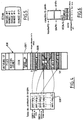
- the terminal comprises a microprocessor (81), a VRAM video memory (83), a random access memory (82) character generator and a management circuit (85), is characterized in that said circuit management (85) manages on the one hand the video display and on the other hand the read or write accesses to the VRAM video memory (83) which constitutes on the one hand the system memory for memorizing the code necessary for the operation of the terminal and on the other hand the display memory to store the code and the attributes of the characters to be displayed; said management circuit (85) being connected on the one hand, by a first data bus (8549) and a first address bus (8558) to the microprocessor (81), by a parallel data bus (8546) and a serial data bus (8548) to the VRAM video memory (83) and on the other hand, by a second address bus (8528) and a second data bus (8529) to a random access memory (82) character generator and by five output lines to the video monitor (8530, HRTL, VRT).
- said circuit management (85) manages on the one
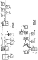
- the management circuit (85) comprises, in addition to the management circuits (8556), read and write accesses from the video memory and the control circuits (85477) for the access cycles and the serial offset of the memory.
- video a circuit (8503 to 8506) for storing the code and the attribute of a current character to send the attributes to the attribute controller circuit (853), a circuit (8520 to 8523) for storing the data constituting the pattern of a character from the character generating RAM (82).
- the circuit making it possible to store the current pattern is a pipeline consisting of 4 buffer registers (8520 to 8523) in series and the outputs of which are sent to the inputs of the attribute controller circuit (853) according to the signal delivered.
- a pattern counter (ech-pattern) configured as a function of the number of quartets per pattern, these patterns comprising between 9 and 15 pixels per character segment.
- the circuit includes an automaton (8547, 8557) which makes it possible to manage 1 to 132 columns and 1 to 512 lines per screen.
- the automaton manages the interfacing signals with the VRAM video random access memory by delivering the RAS, CAS, DT, OE signals, necessary for the operation of this memory, in particular the refresh and the "data transfer", as well as the serialization signals of the static RAM part.
- a counter (8551) of a configurable character range from 1 to 16 (8508) is used in combination with the character code, and with a quartet counter (8552) configurable between 0 and 3 to provide the address. of the pattern in the character generator, and in that a control circuit (8553) delivers the signals CS, WE, OE necessary for the operation of the random access memory (82) for storing the characters.
- the management circuit (85) of the display comprises HOLD, HOLDA means for managing the exchanges with the microprocessor (81) during the critical moment of loading the serializer of the VRAM, and this in order to prevent the microphone to access the VRAM; the contention of access to this VRAM by the microphone and the video being thus resolved during the transfer of a row in the serializer.
- the circuit makes it possible to store the code and the attribute of a character is a pipeline consisting of a first set of buffer registers (8500 to 8503) in series and a second set (8504 and 8506) of buffer registers each connected respectively at the output of a register of the first set and loaded at the rate of the signal of a modulo n counter, n being the number of registers of the first set.
- the management circuit includes a pointer counter (85471), the triggering of which is carried out in advance with respect to the loading of the address of the row being processed.
- the management circuit (85) comprises an addressing management circuit (85472) making it possible to transfer data from the memory to the management circuit (85), either by the parallel bus (8546) , or by the serial bus (8548) according to the sequence of signals sent by the control circuit (85477) of the access cycles and the offset.
- the addressing management circuit (85472) comprises a multiplexer (854720) with 8 input bytes and a 9-line output among eight possibilities. address according to the signals supplied by the circuit (8557) for controlling and commanding the addressing circuit as a function of the access cycle chosen.
- two of the eight address possibilities are provided by the addresses of the bus connecting the management circuit to the central processor (81) selected by a central processor (CPU) access cycle to the VRAM (83).
- two of the eight possibilities are respectively the outputs of an 8-bit counter (85475) reset to zero by the signal (NF) indicating a new frame, and incremented with each new row of characters displayed, and on the other hand, the outputs of a buffer register (8549) receiving as input 8 address bits supplied by the central processor and defining the start of the scoreboard address (8301) at each new row of characters, and selected by a call cycle to load the address of the current row pointer.
- two others of the eight possibilities are the 8 low address bits and 8 high address bits of the current row pointer constituted by the outputs of a register pipeline (85473) selected by a data transfer cycle. to load the current row address in the VRAM before each start of a new screen line, and this before clearing the serializer of the VRAM.
- two other of the eight possibilities are the 8 bits of low address and 8 bits of high address of a pointer counter (85470, 85471) loaded before each start of screen line by the address of the pointer of current row with a counting anticipation of one unit to define the address of the next physical row of the VRAM when the comparison circuit (85476) detects an end of a physical row and therefore initiates a data transfer cycle in real time.
- a pointer counter 85470, 85471
- the dynamic memory (830) contains on the one hand the interrupt vectors, the stack management registers, the line buffers and on the other hand a time table (8301).
- Another object of the invention is to propose a management circuit making it possible to optimize the cost of a terminal.
- the circuit for managing a video memory, a random access memory generating character and the display of a terminal is characterized in that it comprises, in a monolithic integrated circuit, management circuits (8556) for access to read and write from video memory, an automatic controller (85477) for access, refresh, data transfer and serial offset cycles in video memory, a control circuit ( 8553) delivering the signals CS, WE, OE necessary for the operation of the character generator RAM (82), an attribute controller circuit connected to a first buffer circuit (8503 to 8506) for storing the code and the attribute of a current character, coming from the video memory, to send the attribute of each character to the attribute controller circuit (853), a second buffer circuit (8520 to 8523) for storing the data constituting the pattern of a character, from the character generator random access memory (82) for sending the pattern to the attribute controller circuit (853).
- a pattern counter (ech-pattern configured as a function of the number of quartets per pattern, the patterns comprising between 9 and 15 pixels per character slice, a character slice counter (8551) that can be configured from 1 to 16 (8508 ) whose output is associated with the character code and with a quartet counter (8552) configurable between 0 and 3 to provide the address of the pattern in the character generator.
- the automaton (85477, 85557) of the management circuit makes it possible to manage 1 to 132 columns and 1 to 512 lines per screen.
- the management circuit (85) of the display comprises means on the one hand of supplying a first HOLD signal corresponding to a request for bus takeover and on the other hand of receiving and processing a second signal HOLDA allowing to manage the exchanges with the external circuit (81) during the critical moment of loading of the serializer of the VRAM, and this in order to prevent an external circuit from accessing the VRAM; the contention of access to this VRAM being thus resolved during the transfer of a row in the serializer.
- the management circuit makes it possible to store the code and the attribute of a character is a pipeline consisting of a first set of buffer registers (8500 to 8503) in series and a second set (8504 and 8506 ) of buffer registers connected respectively each at the output of a register of the first game and loaded at the rate of the signal of a modulo n counter, n being the number of registers of the first game.
- the management circuit includes a pointer counter (85471), the triggering of which is carried out in advance with respect to the loading of the address of the row being processed.
- the management circuit (85) comprises an addressing management circuit (85472) making it possible to transfer data from the memory to the management circuit (85), either by the parallel bus (8546) , or by the serial bus (8548) of the video memory according to the sequence of signals sent by the control circuit (85477) of the access cycles and of the offset.
- the addressing management circuit (85472) comprises a multiplexer (854720) with 8 input bytes and a 9-line output among eight address possibilities according to the signals supplied by the circuit (8557). control and command of the addressing circuit according to the chosen access cycle.
- two of the eight address possibilities are provided by the addresses of the bus connecting the management circuit to a central processor (81) selected by a central processor access cycle (CPU) to the VRAM (83).
- two other of the eight possibilities are respectively the outputs of an 8-bit counter (85475) reset to zero by the signal (NF) indicating a new frame, and incremented with each new row of characters displayed, and on the other hand, the outputs of a buffer register (8549) receiving as input 8 address bits supplied by the central processor and defining the start of the scoreboard address (8301) at each new row of characters, and selected by a call cycle to load the address of the current row pointer.
- two others of the eight possibilities are the 8 low address bits and 8 high address bits of the current row pointer constituted by the outputs of a register pipeline (85473) selected by a data transfer cycle. to load the current row address in VRAM before each start of a new screen line, and this before clearing the VRAM serializer.
- two other of the eight possibilities are the 8 bits of low address and 8 bits of high address of a pointer counter (85470, 85471) loaded before each start of screen line by the address of the pointer of current row with a counting anticipation of one unit to define the address of the next physical row of the VRAM when the comparison circuit (85476) detects an end of a physical row and therefore initiates a data transfer cycle in real time.
- a pointer counter 85470, 85471
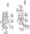
- the terminal architecture according to the invention shown in FIG. 1 comprises a microprocessor (81) connected by an 8-bit data bus to a video circuit (85) for managing the display on a monitor (84) and exchanges with a character generator RAM memory (82), a RAM video type random access memory (VRAM, 83).
- the connection between the microprocessor (81) and the management circuit (85) is done through an 8-bit data bus (8549).
- the connection between the management circuit (85) and the monitor (84) is carried out by a 5-line bus (8530) delivering the red (R), green (V), blue (B), horizontal return (HRTC) signals. ), vertical return (VRT).
- the connection between the management circuit (85) and the character-generating static random access memory (SRAM) (82) is carried out by an address bus (8528) with 14 address lines and by a data bus (8529) 4 lines of data.
- the connection between the management circuit (85) and the VRAM video memory (83) is made on the one hand for the parallel part by an address bus (8547) with 9 address lines and by a local data bus (8546) with 4 data lines and on the other hand for the serial part by a bus of 4 lines (8548).
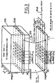
- VRAM is made up of a standard dynamic RAM which is accessed by conventional 'parallel' bus, and a fast static RAM, called serializer, and configured as a shift register that can be read by 'serial bus', all in the same housing ( Figure 3); the coupling between the 2 memories is carried out by bringing a row of words read in the DRAM into contact with the inputs of the shift register, the 'parallel' loading command of the shifter being made at a very precise instant specified by the VRAM in synchronization with the shift clock. It is this simultaneous transfer of all the words in a row on a very 'large bus' internal to VRAM which gives it a large bandwidth. Since VRAM is essentially dynamic RAM, the price of the bit is therefore minimized; of course, its control logic is more complex since it requires a cell refresh automaton and a transfer logic from DRAM to static RAM called 'shifter'.
- FIG. 3 represents the organization of a VRAM video memory in which a part (830) is constituted by a dynamic random access memory of, for example, 256 Kmots of 4 bits, these 256 Kmots being organized in 512 rows of 512 columns.
- a row n (8300) 4 4-bit words constitute the 16 bits of information corresponding to the 8 code bits and the 8 attribute bits defining the code and the attribute (CODATT) of the character to be displayed in a row screen.
- These 4 nibbles are called respectively (CH) for the high code and (CL) for the low code of the character and (AH) for the high attribute, (AL) for the low attribute.
- a memory array slice (8300) is transferred by the bus (832) of 512 x 4 bits to the memory vivid static (831) formed of 512 x 4 bits.
- This memory is in fact made up of 4 registers of 512 bits whose serial outputs constitute the 4 lines of the serial bus (8548).
- a memory slice (8300) allows the storage of 128 CODATT information corresponding to each character of a screen which could, in this way, contain a maximum of 128 columns of characters.
- FIG. 4 represents the logical organization of the dynamic random access memory (830), and FIG. 5 a screen formed by 25 rows of (x) columns of characters, the number of columns being able to vary between 80 and 132.
- the characters can have a dimension between 1 and 15 representation points per slice, each character comprising from 1 to 16 slices in patterns.
- the dynamic memory (830) can be organized so as to contain the interrupt vectors, the registers necessary for the management of stacks, line buffers, the code necessary for the operation of the terminal and, in particular, for the management of the display and communications by a line interface (87) connected by the bus (8549) to the microphone (81) and to the management circuit (85) as shown in Figure 1.
- a 'boot' located in ROM to download to the terminal, via the local network, its presentation program from the data concentrator; in the terminal, this code to be executed by the microphone is housed in the DRAM part of VRAM with the image buffers, which requires a larger memory: rather use a VRAM with a capacity of 256 K x 4.
- a VRAM memory of 64 K x 4 may suffice since the microphone executes the code in ROM only.
- This memory (830) also contains a pointing table (8301) containing, as shown on the left of FIG. 4, the table pointer (83011) and the various row pointers including the current row pointer (8301), these pointers defining the addresses of the rows corresponding to the memory portions such as (8300) for row number 1 for example in which all of the CODATT information corresponding to each of the characters constituting a row for display on the screen are contained in the memory.
- a pointing table (8301) containing, as shown on the left of FIG. 4, the table pointer (83011) and the various row pointers including the current row pointer (8301), these pointers defining the addresses of the rows corresponding to the memory portions such as (8300) for row number 1 for example in which all of the CODATT information corresponding to each of the characters constituting a row for display on the screen are contained in the memory.
- the representation of a character is carried out by 16 sections of 9, 10 or 15 points depending on the size of the character and these representations are stored in the static memory (82) constituting the character generator.
- This information is stored in the form of referenced quartets (nib 0 to nib 3), the number of which depends on the number of points of each character. These quartets are stored at defined addresses in the memory.
- the character H is represented by a matrix of 10 points x 9 lines, the nib 2 quartet of slice 0 will have the value in hexadecimal 8, the nib quartet 1 the hexadecimal value 0 and the quartet nib 0 the hexadecimal value 4.
- Each of these quartets will constitute the 4 pieces of information sent in series on the 4 lines of the bus (8529), this piece of information making it possible to reconstruct the section 0 of the letter H for a 10-point character.
- 3 or 4 nibbles are memorized in the memory 82 according to the size of the character of 8, 9, 10 or 15 points.
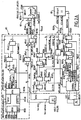
- the circuit (85) makes it possible to manage the exchanges between the different constituent elements of the terminal.
- a first subset constituting the management of transfers between the microphone (81) and the dynamic memory part of the VRAM memory is formed by a logic for managing the write and read transfers (8556, FIG. 2A) between these elements and physical circuits allowing this connection.
- This management logic (8556) generates inter alia the signal SELVRAM (85564) to the sequencer (85477) which supplies the rhythm of the control signals to the VRAM.
- the SELVRAM signal is a simple bus address decoding (8558).
- the physical circuits consist of a multiplexer (8541) connected to the 8 lines of the data bus (8549) of the microphone (81) and receiving on a write multiplexing control input the signal (85561) coming from the management logic. (8556).
- This write multiplexing signal makes it possible to transform the signals arriving on 8 bits by the bus (8549) into 2 signals of 4 bits which are sent from the multiplexer (8541) to a buffer circuit (8542) whose output is connected by a bus 4 lines (8546) to the 4 data entry lines in the dynamic random access memory of VRAM.
- the buffer circuit (8542) is controlled by an ENBUFECR signal for enabling the write buffer (85562) supplied by a second output of the control logic (8556).
- the memory (FIGS.
- This addressing circuit (85472) is addressed by an addressing circuit (85472) connected at output to the address bus of the DRAM (8547) and at input to the address bus of the microphone (8558).
- This addressing circuit (85472) represented in FIG. 2B, comprises a register (85474) connected at the input to the data bus (8549) of the microprocessor (81) and at the output to a multiplexer (854720) to deliver the 8 bits from the top (FETCH-ADDH) of the current row pointer address (8301X). These 8 bits in the upper part are in fact the address of the start of the scoreboard.
- the lower part (FETCH-ADDL) of the current row pointer address is provided by an 8-bit counter (85475) reset to zero by the signal (NF) indicating a new frame, and incremented with each new row of characters by the Fetch-request (FR) signal.
- a NIB logic (85563) from the circuit (8556) makes it possible to address the quartet of the DRAM for the 8 multiplexed buses.
- a 6-stage pipeline (85473) receives the 4 lines of the DRAM parallel data bus (8546) as input.
- This pipeline (85473) stores the 6 quartets (24 bits) defining the address of the next row defined by 16 bits as well as its row attribute defining by 8 bits if the row is double height, double width, at the start slow scrolling, at the end of slow scrolling (smooth scroll) or normal.
- the 16 bits of address of the next row delivered at the output of 4 of the buffers of the pipeline (85473) define at the input of the multiplexer (854720) the signals ROW-SR-ADDL address of low register of row and ROW-SR-ADDH address high row register.
- the outputs of the pipeline defining the 16 address bits are also sent as input to a 16 bit pointer counter (85470, 85471) incremented at the rate of the shift of a character CODATT.
- This pointer counter makes it possible to anticipate the counting of a character, as shown in FIG. 7, on the line (85471).
- This address available at the outlet of the pipeline (85473) is loaded into the pointer counter (85470, 85471) before each start of the screen line by the row transfer signal (85570) (figure 7) and is delivered by the circuit (8557 ) which delivers the control signals (8554) and control of the addressing circuit (85472).
- the sequencer (85477) uses the RTDTR, REF, NLDTR and FR signals to generate the sequences of the RAS, CAS, DT, WE, OE (8554) signals necessary for an operating cycle according to a selected mode of the memory (83). To manage the different modes of access to the VRAM memory, this sequencer also plays the role of arbiter; thus, it generates inter alia the HOLD signal which corresponds to a request to take control of the bus (8549) on the part of the video circuit when one of the signals REF, RTDTR, FR or NLDTR of the circuit (85477) is activated. Receiving the HOLDA acknowledgment signal from the microphone, it thus takes control of the microphone bus (8549) to perform the requested cycle.
- the multiplexer (854720) further includes the input lines CPU-ADDL and CPU-ADDH connected to the address bus of the microprocessor (81) and 3 selection inputs SEL-MAO to SEL-MA2 which allow to select 1 input from 8 to present it at the output of the multiplexer (854720) on the bus (8547).
- selection signals SEL-MAO to SEL-MA2 are also supplied by the circuit (8557).
- the VRAM refresh cycle does not use the circuit multiplexer (854720), because the "CAS before RAS" mode of VRAM is used.
- the last CODATT of row number 2 is the character "G” of the syllable RANG of the word "RANGEE 2", the continuation of which is located at the address of next physical row.
- the following physical row address is determined by cycle 4 using the pointer counter which supplies the address of CODATT "E”. In this way, the serializer continuously receiving clk-decal continuously outputs the CODATT "G", then "E", etc.
- a clock circuit (8550) provides the clock and sequencing signals (8510 to 8514) necessary for the operation of the circuits.
- the data bus (8546) is connected by a buffer register (8543) with 4 inputs and whose 4 outputs are connected to a multiplexer circuit with 2 inputs of 4 lines and 8 parallel outputs.
- the 4 lines of the address bus (8546) are also directly connected to 4 of the inputs of the multiplexing circuit.
- the buffer (8543) allows the storage of the 1st data quartet supplied by the data bus (8546) and wait for the presentation of the 2nd quartet supplied directly by the data bus to the second input quartet of a multiplexer (8544) to validate by the read quartet signal (lect-quart 1) the transmission of the 1st quartet to the multiplexer (8544) and by the read multiplex signal (mux-lect) the transmission of the 8 bits formed by the two quartets to the output of the multiplexer.
- the read multiplexer (mux-read) signal is supplied by the line (85564) coming from the logic circuit (8556).
- the read signal of the 1st quartet is provided by the line (85563) coming from the logic circuit (8556).
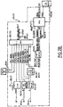
- a subset (8500 to 8503) of the management circuit (85) interfaces the 4-line serial bus (8548) with the character generator memory (82).
- This subset consists of 4 buffer registers (8500 - 8501 - 8502 - 8503) mounted in cascades so as to form a pipeline. These buffer registers are controlled by the same clock signal CLK-CODATT delivered by the line (8510) of the sequencing circuit (8550).
- CLK-CODATT delivered by the line (8510) of the sequencing circuit (8550).
- the outputs of the registers respectively contain the low attributes (AL), the high attributes (AH), the low code (CL) and the high code (CH) of a character of the column (x) of the row (y).
- the 4 output lines of the first buffer register (8500) memorizing the last quartet sent by the memory, are sent to a second buffer register (8506) which will thus store the top quartet of the character code CH (3: 0) in synchronism with the clock signal (8510) CLK-CODATT.
- the outputs of the third buffer register (8502) storing the second quartet emitted by the memory are sent to an additional buffer register (8504) making it possible to store the quartet of high attribute AH (3: 0) of the attributes of the character.
- the AL (3: 0) attribute and CL (3: 0) code quartets of each character are provided directly by the second and third buffer registers (8501 - 8503).
- the 8 lines formed by the 4 ATT lines (7: 4) provided by the register (8504) and the 4 AL lines (3: 0) by the register (8503) constitute the 8 attribute lines sent to the attribute controller (853 ).
- the 4 COD lines (7: 4) of top quartet of the character code delivered by the output of the buffer (8506) are combined with 4 lines (8508) providing the pattern number, with 4 other lines (8507) output from the second buffer register (8501) delivering the low quartets CL (3: 0) of the character code COD (3: 0) and with 2 lines (8509) providing the quartet number of the section to constitute a 14-line bus (8528) commanding the addresses of the random access memory (82).
- the quartet number of the slice corresponds to the elements called nib.
- the first counter (8552) is a modulo 4 counter while the second is a counter modulo 16 configurable according to the number of slices or patterns of a character.
- the static memory also receives by the lines (85530) the control signals supplied by the control logic (8553) and consisting of the signals CS circuit selection, WE write read, OE validation of the outputs.
- the memory output (82) is interfaced with the monitor (84) by a sub-assembly made up of 4 4-bit buffer registers (8520 to 8523) connected in cascades so as to constitute a pipeline and controlled synchronously by a signal clk-gcq clock supplied by the output line (8511) of the sequencing circuit (8550).
- the 4 outputs (8527) of the first buffer register (8523) are sent to 4 inputs of the attribute controller (853) and constitute the down / down quartet (QLL) of the 16 bits of each character slice.
- the 4 outputs (8526) of the second buffer register (8522) are sent to the following 4 lines and constitute the low / high quartet (QLH) of the 16 points making up a character range.
- the outputs (8525) of the third register (8521) are connected to 4 other circuit input lines (853) and constitute the high / low quartets (QHL) of the 16 points of a character slice and finally the 4 lines of output (8524) from the fourth register (8520) are sent to the other 4 input lines of the video attribute controller (853) to constitute the up / up quartet (QHH) of the 16 points of a character slice.
- the attribute controller circuit (853) also receives an ech-pattern clock signal from the line (8512) of the sequencing circuit (8550).
- the attribute controller in addition to the 3 lines (8530) delivers an output (HRTC) horizontal return and an output (VRT) vertical return to the monitor (84).
- a controller loads the table start address of the addresses of character rows in the current row pointer buffer (85473); the latter will be reloaded before each start of a new row of characters with the address of the start of the next row from the table of row pointers (FIGS. 4 and 7). Then, during the horizontal returns of each active video line, a command to transfer this buffer both to the inputs of the 'pointer' counter (85470, 85471) and to the pointer of the VRAM then makes it possible to communicate this current row start address in the shift register, the latter being ready to shift the CODATT words from the loaded address.
- the shifter which outputs on the VRAM serial bus the CODATT (i) is validated for i varying from 1 to 132 for example.
- Any given row N (8300) of the VRAM contains 512 nibbles (figure 3), numbered from 0 to 511, ie 256 bytes which can accommodate 128 CODATT maximum of 16 bits; in the case of the display mode in 132 characters per line, we are led to reloading 'in real time' during the video line in order to complete the CODATTs of the current row of characters.
- an end of row detection threshold determined by the circuit is fixed (85476); when the outputs of the 'pointer' counter in row N of the VRAM coincide with this threshold, an automaton initiates a 'real time' transfer request RTDTR in order to transfer the row N + 1 of the VRAM.
- This transfer which takes place at a very precise time specified by the VRAM must be synchronous with the end of serialization of the last datum, namely the 511th quartet of row N of the VRAM; once the loading has been executed, the shifter then begins to output the following CODATT data from the first quartet 0 of row N + 1 of the VRAM.
- the ATT attribute is sent to the attribute controller (853) and the COD code is associated with the character slice number or pattern number), supplemented by an address defining high or low nibble; this 13-bit GC address makes it possible to extract the current character pattern of the character generator from a 4-bit bus SRAM memory, all in the unit of time of a character (FIG. 7).
- a command to the attribute controller informs it that a couple [ATT (7: 0)] (i) and [MOTIF (15: 0) ] (i) (or MOTIF (8: 0) for 132 columns) associated with the character i of the screen is available; the attribute controller then samples it and then processes it (see also patent number EP87400711.5 of 01.04.87) into R, G, B signals intelligible by the cathode-ray tube monitor.
- the sampling frequency of the attribute controller obviously follows the character frequency.
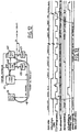
- the reference (130) represents the scanning control signals with the reference (1300) representing the vertical return signal delivered by the VRT output and the references (1301) representing the horizontal return signals delivered by the HRTC output.
- the reference (8301x) represents the current row pointer and its evolution over time.
- the reference (8508) represents the value of the slice or pattern number evolving between 0 and 11 in the case of a character comprising 12 slices.
- the reference (85470) represents the loading of the pointer counter with the value of the pointer of current row, this before carrying out a transfer of rows, and serializing this row then.
- each row has 132 characters and the address of the character to be displayed is determined by adding to the value of the row pointer (85470) the value of a modulo 4 counter which gives the least significant addresses of the character.
- a modulo 4 counter which gives the least significant addresses of the character.
- To this low weight part defining the number of the character in the column there is a second low weight part constituted by the output of the counter (85471) which defines the address of the quartet of the word CODATT addressed in the memory, this word CODATT being made up of 4 quartets.
- the pointer counter assembly consists of the counters (85470 -85471) and operates at the same frequency as the CLK-CODATT character clock.
- the counter (85471) carries out a counting anticipation which makes it possible to know the address of the first quartet of CODATT as soon as the character pointer of the next column in the same row is loaded.
- the character quartets are transferred from the VRAM to the SRAM by the commands of the cycle control circuit (8557) and are shifted in series at the rate of the clock clk-decal represented by the line (85131) consisting of the output of a counter 85230 modulo n which can be parameterized between 0 and 132 and whose clock input receives a clock signal of frequency (8513) corresponding to that of the signal clk-decal.
- the 4 quartets output in series are temporarily stored in the buffer registers (8500 to 8503) at the rate of the clk-codatt clock represented by the line (8510). This clock corresponds to a signal of the same frequency as the clk-decal clock but offset by a period.
- the lines (8500 to 8503) represent the contents of the corresponding buffers of Figure 2 at the time of character processing. These lines also represent the shift of the characters in time as a function of the clock signal clk-codatt so that at the time of the appearance of the ech-cod-att pulses corresponding to the character 0 represented by the arrows 134, 135, 136 the quartets of this character CH-O, CL-O, AH-O, AL-O are found respectively in the registers (8500 - 8501 - 8502 - 8503).
- the transfer of the characters CH-O and AH-O takes place in the buffer registers (8504 - 8506) and the attributes of the character O appear at the input of the circuit (853) while the character code O is combined with the pattern number and the digitized character quartet number to serve as an address for addressing the RAM memory (82).
- the quartet number is provided by a counter (8552) receiving a clock signal (8511) of the same frequency as the clock signal clk-gcq but shifted forward by half a period.
- This counter (8552) can be configured between 0 and 4 to count a number of nibbles depending on the number of dots represented in a character range.
- the pattern number is provided by the output (8508) of the circuit (8551) which is actually a character slice counter which can be set between 0 and 16, this pattern number counter being incremented by 1 each time the quartet counter will have reached the maximum value for which it has been set.
- the control circuit (855) supplies via the control part (8553) the signals CS; WE and OE necessary for the operation of the RAM (82) in reading and this delivers on the bus (8529) the data constituting the points of a slice of a character.
- These data are provided in the form of quartets called QLL QLH QHL QHH which are loaded progressively into the buffer registers (8520 to 8523) at the rate of the clock clk-gcq supplied by the line (8511).
- a synchronization signal (8512) providing the ech-pattern signal and constituted by the output of a programmable counter as a function of the number of display points of a character, in this case here 9.
- This signal makes it possible to carry out the transfer of the quartets from the buffer registers to the attribute controller when the character points necessary for display have been stored.
- the QHH quartet is not used and for this reason, it has not been represented on line (8529) of the diagram in FIG. 13.
Description
La présente invention concerne une architecture de terminal et le circuit de gestion associé.The present invention relates to a terminal architecture and the associated management circuit.
La plupart des fabricants de systèmes informatiques centraux (mainframe) disposent de deux types de terminaux alphanumériques : les terminaux G (5) (figure 8) disposés en grappe sur un réseau local relié par un serveur (3) à un frontal (2) le plus souvent (proprietary) issus d'une expérience acquise avant l'élaboration de la plupart des standards de réseaux locaux et géré par un concentrateur de données, et les terminaux monoconsoles M (4) connectés à des systèmes (1), soit directement sur un même site, soit à travers des modems (24). Les différences essentielles en matière d'électronique sont ainsi les modules de communication et également les tailles des mémoires RAM et ROM présentes sur la carte logique gérée par microprocesseur. Pour des terminaux produits en grandes quantités, les différentes architectures ont un impact non négligeable sur le coût global du terminal ; et le choix de mémoires standards commercialisées par de multiples fabricants de par le monde est un des axes principaux guidant l'architecture. Le module vidéo contrôlant l'affichage du terminal dispose en général de RAM dont la capacité s'accroît en fonction des tailles de mémoire nécessaire aux multiples protocoles de présentation des différentes émulations de terminaux disponibles au catalogue du constructeur. De plus, la qualité d'affichage demandée par les utilisateurs implique la construction de terminaux dont la fréquence de balayage ligne voisine 32 KHz et dont la fréquence de rafraîchissement de l'écran est au-deçà de 70 Hz. La conséquence est l'augmentation de la fréquence caractère et la diminution des temps d'accès aux mémoires d'affichage. Ainsi, les fréquences caractère pour afficher 80 colonnes ou 132 colonnes atteignent respectivement 3,5 et 6 MHz.Most manufacturers of central computer systems (mainframe) have two types of alphanumeric terminals: G terminals (5) (Figure 8) arranged in a cluster on a local network connected by a server (3) to a front end (2). more often (proprietary) from experience acquired before the development of most local network standards and managed by a data concentrator, and the M (4) monoconsole terminals connected to systems (1), either directly on the same site, either through modems (24). The essential differences in electronics are thus the communication modules and also the sizes of the RAM and ROM memories present on the logic card managed by microprocessor. For terminals produced in large quantities, the different architectures have a significant impact on the overall cost of the terminal; and the choice of standard memories marketed by multiple manufacturers around the world is one of the main axes guiding architecture. The video module controlling the display of the terminal generally has RAM, the capacity of which increases as a function of the memory sizes required for the multiple presentation protocols for the various terminal emulations available in the manufacturer's catalog. In addition, the display quality demanded by users involves the construction of terminals whose line scan frequency is around 32 KHz and whose screen refresh frequency is below 70 Hz. The consequence is the increase in character frequency and the decrease in access time to display memories. Thus, the character frequencies for displaying 80 columns or 132 columns reach 3.5 and 6 MHz respectively.
Dans les terminaux, une image standard de 25 rangées de 80 colonnes est décrite en mémoire vidéo par 25 fois 80 mots de 16 bits ; ces 16 bits se composent en général du code ASCII sur 7 ou 8 bits et des attributs sur 8 bits de chaque caractère permettant d'obtenir les rendus visuels associés à chaque attribut de caractère, par exemple 'souligné', 'clignotant', 'inversion vidéo'... L'association du code et de l'attribut représente 15 à 16 bits et sera par la suite appelée le CODATT du caractère donné. Une telle image nécessite 25 x 80 x 2 octets = 4 Koctets de RAM pour la mémoire video ; de la même manière, pour 132 colonnes, on a besoin de 25 x 132 x 2 = 6,6 Koctets, et pour une image de 43 rangées de 132 colonnes : 11,4 Koctets ou 5,7 Kmots de 16 bits. Cette image représente tous les caractères que l'on peut visualiser simultanément sur un écran ; cette image est donc la représentation de tout ou partie du tampon (buffer) image stockée en memoire centrale (ou mémoire système du microprocesseur) et est constituée par les caractères envoyés par l'unité centrale et reçus par le terminal ; ces caractères s'accumulent dans le tampon (buffer) ligne 87, (figure 9) avant d'être traités par le microprocesseur et envoyés dans le tampon (buffer) image (41) ; enfin, le processus de visualisation transfère à son tour ces caractères du tampon (buffer) image (41) vers la mémoire d'écran (44). Ainsi, on est conduit à recevoir des images successives qu'on affiche soit en mode bloc : 25 rangées mise à jour à la fois, soit en mode défilement continu : la première rangée est effacée, les 24 rangées suivantes montent d'une position et la dernière rangée seulement est remplacée par la nouvelle rangée. Par conséquent, dans le cas de défilement d'images successives sur l'écran, on est conduit à recharger chaque image issue de la mémoire vidéo (41) dans la mémoire d'écran (44) (figure 9). Une bonne vitesse de mise à jour de l'écran entraîne une bonne ergonomie d'affichage pour l'utilisateur. On parvient à ce niveau de qualité quand on a un débit supérieur de 50000 nouveaux caractères par seconde pour les applications tournant sur les types de terminaux cités précèdemment. L'ergonomie d'affichage associée aux différentes présentations implique la prise en compte de fonctionnalités telles que le défilement lent dans des bandeaux ('tranches' d'écran horizontales). Dans tous les cas étudiés par la suite, on fait référence au mode 132 colonnes qui est le plus pénalisant en terme de vitesse ; il impacte donc davantage l'architecture et entraîne le plus souvent le choix de mémoires plus rapides et donc plus chères.In the terminals, a standard image of 25 rows of 80 columns is described in video memory by 25 times 80 words of 16 bits; these 16 bits generally consist of the 7 or 8 bit ASCII code and the 8 bit attributes of each character making it possible to obtain the visual renderings associated with each character attribute, for example 'underlined', 'flashing', 'inversion video '... The association of the code and the attribute represents 15 to 16 bits and will subsequently be called the CODATT of the given character. Such an image requires 25 x 80 x 2 bytes = 4 kbytes of RAM for video memory; in the same way, for 132 columns, we need 25 x 132 x 2 = 6.6 Kbytes, and for an image of 43 rows of 132 columns: 11.4 Kbytes or 5.7 Kmots of 16 bits. This image represents all the characters that can be viewed simultaneously on a screen; this image is therefore the representation of all or part of the image buffer stored in central memory (or microprocessor system memory) and is made up of the characters sent by the central unit and received by the terminal; these characters accumulate in the buffer (buffer)
Les différents moyens de transfert de données entre la mémoire système (41) et la mémoire d'écran (44) se font soit par mise à jour par le microprocesseur (81) (figure 9), soit par D.M.A. Accès Direct Mémoire (figure 14). Pour la mise à jour par le micro, on rencontre habituellement 2 techniques suivant que le micro dispose de plus ou moins de bande passante pour effectuer la mise à jour de la mémoire d'écran (44). Cette dernière étant constituée d'une mémoire à double accès, dédiée à l'écran et partagée entre le micro et le contrôleur vidéo. Le fait d'utiliser 2 types de mémoire séparées, mémoire système (41) et mémoire d'écran (442, 441) (figure 10), augmente le coût de la réalisation. Dans un premier cas, le micro peut disposer de la moitié de la bande passante de la vidéo ; c'est ce qu'on obtient quand on partage, comme représenté figure 11 par la ligne fenêtre, l'horloge caractère en 2 intervalles de temps, l'un attribué au micro pour, par exemple, écrire un mot de mise à jour, l'autre au contrôleur vidéo pour la lecture permanente et successive des mots constituant la mémoire d'écran. Dans l'autre solution représentée figures 13 et 14, le micro dispose d'une portion très réduite de bande passante vidéo lui permettant d'écrire le nouveau mot dans un tampon si le tampon est 'vide', la mise à jour effective se faisant par un automate pendant les retours de ligne horizontaux.The various means of transferring data between the system memory (41) and the screen memory (44) are done either by updating by the microprocessor (81) (FIG. 9), or by D.M.A. Direct Memory Access (figure 14). For updating by the microphone, there are usually 2 techniques depending on whether the microphone has more or less bandwidth to update the screen memory (44). The latter being made up of a dual access memory, dedicated to the screen and shared between the microphone and the video controller. The fact of using 2 types of separate memory, system memory (41) and screen memory (442, 441) (FIG. 10), increases the cost of production. In a first case, the microphone can have half of the video bandwidth; this is what we get when we share, as shown in figure 11 by the window line, the character clock in 2 time intervals, one assigned to the microphone for, for example, writing an update word, the other to the video controller for permanent and successive reading of the words constituting the screen memory. In the other solution represented in FIGS. 13 and 14, the microphone has a very reduced portion of video bandwidth enabling it to write the new word in a buffer if the buffer is 'empty', the actual updating being carried out by an automaton during horizontal line feeds.
La figure 10 représente une réalisation basée sur le principe du partage de bande passante, associée à la figure 14 pour les chronogrammes. Ce type de mise en oeuvre nécessite des RAM statiques de temps d'accès nettement inférieur à la période d'horloge divisée par 2 ; on trouve par exemple pour 132 colonnes avec une horloge caractère de 170ns un temps d'accès de 35ns, et ce pour les 2 mémoires (442, 441) comprenant les 'CODATTs'. Ainsi, quand on désire répondre aux exigences dictées par plusieurs émulations, on est conduit à prendre la taille mémoire couvrant l'émulation la plus gourmande en mémoire, à savoir pour notre application des RAM statiques donnant 8 kmots de 16 bits (pour les 5,7 Kmots nécessaires). Cette solution implique le choix de 2 mémoires statiques rapides de 8 K x 8 à temps d'accès de 35ns, qui constituent une solution chère car en dehors des standards de RAM statiques plutôt centrés autour de 100ns. Le micro prépare la mise à jour en tamponnant les adresses des CODATTs seulement. Ainsi, cette solution laisse au microprocesseur moins de 50 pour cent de bande passante potentielle côté vidéo ; on approche les 14 mises à jour maximum ('CODATTs') par ligne vidéo de fréquence 32 KHz, donnant un débit potentiel maximal de 450000 caractères nouveaux par image, solution amplement suffisante, et ce, malgré le ralentissement accru du micro pour ses accès vidéo. En effet, à chaque accès vidéo, le micro est ralenti par l'asynchronisme entre son cycle et la fenêtre qui lui est attribuée, reportant ainsi le cycle d'écriture à la fenêtre 'micro' suivante, ce qui implique la mise en attente (wait) du micro et la présence de 2 tampons 470, 471 buffers (figures 10 et 11) ; il s'ensuit une certaine perte de bande passante du micro, dépendant également du programme du processus de visualisation.FIG. 10 represents an embodiment based on the principle of sharing bandwidth, associated with FIG. 14 for the timing diagrams. This type of implementation requires static RAMs with access times significantly lower than the clock period divided by 2; we find for example for 132 columns with a character clock of 170ns an access time of 35ns, and this for the 2 memories (442, 441) comprising the 'CODATTs'. Thus, when we want to meet the requirements dictated by several emulations, we are led to take the memory size covering the most memory-intensive emulation, namely for our application of static RAM giving 8 kmots of 16 bits (for the 5, 7 Kmots required). This solution implies the choice of 2 fast static memories of 8 K x 8 with access time of 35ns, which constitute an expensive solution because outside the static RAM standards rather centered around 100ns. The microphone prepares the update by buffering the addresses of the CODATTs only. Thus, this solution leaves the microprocessor with less than 50 percent of potential video bandwidth; we approach the maximum 14 updates ('CODATTs') per video line with a frequency of 32 KHz, giving a maximum potential bit rate of 450,000 new characters per image, an ample solution, despite the increased slowdown of the microphone for its video access . Indeed, with each video access, the microphone is slowed down by the asynchronism between its cycle and the window which is allotted to him, thus deferring the writing cycle to the next window 'microphone', which implies putting on hold ( wait) from the microphone and the presence of 2
La figure 12 représente une configuration basée sur le principe de la portion de bande passante réduite correspondant également au brevet numéro EP-A-0 244 280 du 01.04.87. Dans la partie active de la visualisation, comme représenté sur le chronogramme de la figure 13, le contrôleur (43) lit en permanence les différentes positions de la mémoire vidéo (442, 441) afin de recueillir les 'CODATT(i)', pour i de 1 à 132, associés aux 132 caractères de chaque rangée d'écran et ce, au rythme de l'horloge caractère, ce qui conduit à effectuer un cycle de lecture d'un mot de 16 bits en 170ns pour le mode 132 colonnes.FIG. 12 represents a configuration based on the principle of the reduced bandwidth portion also corresponding to patent number EP-A-0 244 280 of 01.04.87. In the active part of the display, as shown in the timing diagram of FIG. 13, the controller (43) constantly reads the different positions of the video memory (442, 441) in order to collect the 'CODATT (i)', for i from 1 to 132, associated with the 132 characters of each screen row and this, at the rate of the character clock, which leads to performing a reading cycle of a 16 bit word in 170ns for the 132 column mode .
Le micro prépare la mise à jour en tamponnant cette fois les adresses et dans les registres (470, 471) les données du mot 'CODATT' et un automate exécute la commande pendant le prochain retour horizontal du spot ; en effet, pendant ce 'retour ligne', le spot qui excite le phosphore sur le tube cathodique est éteint, et par conséquent le contrôleur vidéo n'a pas besoin de lire la mémoire vidéo. On évite ainsi la gestion de l'entrelacement des accès du micro et du contrôleur vidéo comme précédemment. Ici, on est amené à utiliser de la mémoire statique plus lente : 2 RAM de 8 K x 8 de temps d'accès 100ns suffisent et rendent cette solution moins chère que la précédente. Cependant, le débit de mise à jour reste plus modeste, avoisinant les 30000 nouveaux caractères par seconde, ce qui reste très insuffisant pour obtenir les performances demandées. De plus, on observe un phénomène de performances d'affichage par 'palier' dû à la simultanéité du vidage du buffer ligne et du remplissage du buffer écran, conjugués avec la limitation à une mise à jour par ligne vidéo.The microphone prepares the update by buffering this time the addresses and in the registers (470, 471) the data of the word 'CODATT' and an automaton executes the command during the next horizontal return of the spot; in fact, during this 'line feed', the spot which excites the phosphorus on the cathode ray tube is switched off, and therefore the video controller does not need to read the video memory. This avoids the management of the interlacing of the accesses of the microphone and the video controller as previously. Here, we have to use slower static memory: 2 RAM of 8 K x 8 of access time 100ns are enough and make this solution less expensive than the previous one. However, the update rate remains more modest, around 30,000 new characters per second, which is still very insufficient to obtain the requested performance. In addition, we observe a phenomenon of display performance by 'level' due to the simultaneous emptying of the line buffer and the filling of the screen buffer, combined with the limitation to an update per video line.
Dans une autre technique de mise à jour par accès direct à la mémoire DMA (figure 14), on dispose de 2 mémoires (420, 421) de type FIFO de profondeur 132 colonnes et de largeur 16 bits permettant le stockage de 2 rangées consécutives de l'écran (figure 14) ; pendant que l'on vide une FIFO (420) représentant les 80 ou 132 mots CODATT de la rangée n (ce qui s'apparente à la lecture permanente de la mémoire d'écran par le contrôleur vidéo dans les 2 exemples précèdents), on remplit l'autre FIFO (421) avec les 80 ou 132 mots CODATT de la rangée n+1, si possible avec la plus grande bande passante. On est donc conduit à l'utilisation d'un contrôleur de DMA très performant qui sache faire une lecture de donnée mémoire système (41) en même temps que son écriture dans la FIFO (421), d'ou la recopie des données CODATT de la rangée n+1 issues de la mémoire système (41) dans cette FIFO (421). La mémoire vidéo dédiée se réduit ici à 2 FIFOs. Cette solution est complexe à réaliser, gourmande en bande passante (de l'ordre de 35 % malgré un DMA performant et ce, pour 12 lignes vidéo par rangée), mais permet des performances d'affichage de 530000 nouveaux caractères par seconde. Néanmoins, elle exige 3 mémoires FIFO dans le cas de défilement lent dans des bandeaux d'écran (SMOOTH SCROLL) ce qui dégrade encore plus la bande passante du micro ; en effet, cette fois, on est obligé d'avoir la possibilité de recharger 2 FIFOs dans le temps de 12 + 1 lignes vidéo ce qui fait passer les 35% à 64%. Dans ce cas, il ne reste plus au micro qu'une bande passante limitée à environ 36%, ce qui peut se révéler insuffisant quand une partie de cette bande est affectée au DMA du réseau local. De plus, cette dernière solution se prête assez mal à l'intégration dans des ASICs de type prédiffusés pour peu qu'on veuille y inclure les FIFOs ; en effet, la puce devient grosse et moins adaptée aux exigences de prix bas envisagé ; des constructeurs de circuits intégrés ont déjà réalisé de telles puces 'custom', sans toutefois y intégrer la partie contrôleur d'attribut (figure 14) ; ce dernier reçoit les CODATT, et les motifs (ou tranches de caractères) issus du générateur de caractères avant de les transformer en signaux Rouge, Vert, Bleu 'intelligibles' pour le moniteur. Un des buts essentiels dans la construction de terminaux bas coût est au plan logique électronique d'intégrer le plus de composants à un prix optimal, ce qui passe par l'intégration du contrôleur d'attribut qui est en général spécifique à chaque constructeur à cause des diverses émulations de terminaux supportées par le passé. Dans les solutions balayées ci-dessus, nous avons toujours soit un surcoût dû à l'ajout d'une mémoire dédiée, soit un problème de performance d'affichage. Il est connu également par la demande de brevet EP 0259827 un terminal utilisant un microprocesseur relié directement à une vidéo RAM par un bus, cette vidéo RAM étant accédée par un séquenceur d'affichage qui à l'aide de la mémoire générateur de caractère va permettre de générer les informations à l'affichage.In another updating technique by direct access to the DMA memory (FIG. 14), there are 2 memories (420, 421) of FIFO type with
L'objet de la présente invention est de proposer une architecture de terminal employant un boîtier de mémoire VIDEO RAM, ou VRAM, pour obtenir de bonnes performances d'affichage en évitant l'utilisation d'une mémoire dédiéeThe object of the present invention is to provide a terminal architecture employing a VIDEO RAM, or VRAM, memory box to obtain good display performance while avoiding the use of dedicated memory.
Les données constituant le code de caractère doivent être verrouillées dans un tampon et c'est le microprocesseur qui commande le fonctionnement en fournissant le nombre de lignes affichées au séquenceur, une commande de sélection de la forme de caractère à la mémoire génératrice de caractère et une commande de réécriture d'un code de caractère à la vidéo RAM. La gestion de certaines commandes par le microprocesseur pénalise les performances du terminal et, le nombre de boîtiers nécessaires au fonctionnement du terminal grève également le coût de celui-ci. L'objet de la présente invention est de proposer à un terminal employant un boîtier de mémoire vidéo RAM pour obtenir de bonne performance d'affichage et utilisant un circuit de gestion permettant d'optimiser le coût.The data constituting the character code must be locked in a buffer and it is the microprocessor which controls the operation by supplying the number of lines displayed to the sequencer, a command for selecting the shape of the character to the character generating memory and a command to rewrite a character code to RAM video. The management of certain orders by the microprocessor penalizes the performance of the terminal and the number of boxes necessary for the operation of the terminal also increases the cost of the latter. The object of the present invention is to propose to a terminal using a RAM video memory unit to obtain good display performance and using a management circuit making it possible to optimize the cost.
Ce but est atteint par le fait que le terminal comporte un microprocesseur (81), une mémoire vidéo VRAM (83), une mémoire vive (82) générateur de caractère et un circuit de gestion (85), est caractérisé en ce que ledit circuit de gestion (85) gère d'une part l'affichage vidéo et d'autre part les accès de lecture ou d'écriture à la mémoire vidéo VRAM (83) qui constitue d'une part la mémoire système pour mémoriser le code nécessaire au fonctionnement du terminal et d'autre part la mémoire de l'affichage pour mémoriser le code et les attributs des caractères à afficher ; ledit circuit de gestion (85) étant relié d'une part, par un premier bus de donnée (8549) et un premier bus d'adresse (8558) au microprocesseur (81), par un bus parallèle de donnée (8546) et un bus série de donnée (8548) à la mémoire vidéo VRAM (83) et d'autre part, par un second bus d'adresse (8528) et un second bus de donnée (8529) à une mémoire vive (82) générateur de caractère et par cinq lignes de sortie au moniteur vidéo (8530, HRTL, VRT).This object is achieved by the fact that the terminal comprises a microprocessor (81), a VRAM video memory (83), a random access memory (82) character generator and a management circuit (85), is characterized in that said circuit management (85) manages on the one hand the video display and on the other hand the read or write accesses to the VRAM video memory (83) which constitutes on the one hand the system memory for memorizing the code necessary for the operation of the terminal and on the other hand the display memory to store the code and the attributes of the characters to be displayed; said management circuit (85) being connected on the one hand, by a first data bus (8549) and a first address bus (8558) to the microprocessor (81), by a parallel data bus (8546) and a serial data bus (8548) to the VRAM video memory (83) and on the other hand, by a second address bus (8528) and a second data bus (8529) to a random access memory (82) character generator and by five output lines to the video monitor (8530, HRTL, VRT).
Selon une autre particularité le circuit de gestion (85) comporte, outre les circuits de gestion (8556) des accès lecture, écriture de la mémoire vidéo et les circuits de commande (85477) des cycles d'accès et du décalage série de la mémoire vidéo, un circuit (8503 à 8506) permettant de stocker le code et l'attribut d'un caractère courant pour envoyer les attributs sur le circuit contrôleur d'attribut (853), un circuit (8520 à 8523) permettant de stocker les données constituant le motif d'un caractère provenant de la mémoire vive (82) générateur de caractère.According to another particular feature, the management circuit (85) comprises, in addition to the management circuits (8556), read and write accesses from the video memory and the control circuits (85477) for the access cycles and the serial offset of the memory. video, a circuit (8503 to 8506) for storing the code and the attribute of a current character to send the attributes to the attribute controller circuit (853), a circuit (8520 to 8523) for storing the data constituting the pattern of a character from the character generating RAM (82).
Selon une autre particularité le circuit permettant de stocker le motif courant est un pipeline constitué de 4 registres tampons (8520 à 8523) en série et dont les sorties sont envoyées sur les entrées du circuit contrôleur d'attribut (853) en fonction du signal délivré par un compteur motif (ech-motif) paramétré en fonction du nombre de quartets par motifs, ces motifs comprenant entre 9 et 15 pixels par tranche de caractère.According to another particular feature, the circuit making it possible to store the current pattern is a pipeline consisting of 4 buffer registers (8520 to 8523) in series and the outputs of which are sent to the inputs of the attribute controller circuit (853) according to the signal delivered. by a pattern counter (ech-pattern) configured as a function of the number of quartets per pattern, these patterns comprising between 9 and 15 pixels per character segment.
Selon une autre particularité le circuit comporte un automate (8547, 8557) qui permet de gérer 1 à 132 colonnes et de 1 à 512 lignes par écran.According to another particular feature, the circuit includes an automaton (8547, 8557) which makes it possible to manage 1 to 132 columns and 1 to 512 lines per screen.
Selon une autre particularité l'automate (85477) gère les signaux d'interfaçage avec la mémoire vive vidéo VRAM en délivrant les signaux RAS, CAS, DT, OE, nécessaires au fonctionnement de cette mémoire, notamment le rafraîchissement et le "data transfer", ainsi que les signaux de sérialisation de la partie RAM statique.According to another particular feature, the automaton (85477) manages the interfacing signals with the VRAM video random access memory by delivering the RAS, CAS, DT, OE signals, necessary for the operation of this memory, in particular the refresh and the "data transfer", as well as the serialization signals of the static RAM part.
Selon une autre particularité un compteur (8551) de tranche de caractère paramétrable de 1 à 16 (8508) est utilisé en combinaison avec le code du caractère, et avec un compteur (8552) de quartet paramétrable entre 0 et 3 pour fournir l'adresse du motif dans le générateur de caractère, et en ce qu'un circuit de commande (8553) délivre les signaux CS, WE, OE nécessaires au fonctionnement de la mémoire vive (82) de stockage des caractères.According to another particular feature, a counter (8551) of a configurable character range from 1 to 16 (8508) is used in combination with the character code, and with a quartet counter (8552) configurable between 0 and 3 to provide the address. of the pattern in the character generator, and in that a control circuit (8553) delivers the signals CS, WE, OE necessary for the operation of the random access memory (82) for storing the characters.
Selon une autre particularité le circuit de gestion (85) de l'affichage comporte des moyens HOLD, HOLDA de gérer les échanges avec le microprocesseur (81) pendant l'instant critique de chargement du sérialiseur de la VRAM, et ce afin d'empêcher le micro d'accéder à la VRAM ; la contention d'accès à cette VRAM par le micro et la vidéo étant ainsi résolue pendant le transfert d'une rangée dans le sérialiseur.According to another particularity, the management circuit (85) of the display comprises HOLD, HOLDA means for managing the exchanges with the microprocessor (81) during the critical moment of loading the serializer of the VRAM, and this in order to prevent the microphone to access the VRAM; the contention of access to this VRAM by the microphone and the video being thus resolved during the transfer of a row in the serializer.
Selon une autre particularité le circuit permet de stocker le code et l'attribut d'un caractère est un pipeline constitué d'un premier jeu de registres tampons (8500 à 8503) en série et d'un deuxième jeu (8504 et 8506) de registres tampons branchés respectivement chacun en sortie d'un registre du premier jeu et chargés au rythme du signal d'un compteur modulo n, n étant le nombre de registres du premier jeu.According to another particularity, the circuit makes it possible to store the code and the attribute of a character is a pipeline consisting of a first set of buffer registers (8500 to 8503) in series and a second set (8504 and 8506) of buffer registers each connected respectively at the output of a register of the first set and loaded at the rate of the signal of a modulo n counter, n being the number of registers of the first set.
Selon une autre particularité le circuit de gestion comporte un compteur pointeur (85471) dont le déclenchement est effectué de façon anticipée par rapport au chargement de l'adresse de la rangée en cours de traitement.According to another particular feature, the management circuit includes a pointer counter (85471), the triggering of which is carried out in advance with respect to the loading of the address of the row being processed.
Selon une autre particularité le circuit de gestion (85) comporte un circuit de gestion de l'adressage (85472) permettant de faire des transferts de donnée de la mémoire vers le circuit de gestion (85), soit par le bus parallèle (8546), soit par le bus série (8548) selon la séquence des signaux envoyés par le circuit de commande (85477) des cycles d'accès et du décalage.According to another particular feature, the management circuit (85) comprises an addressing management circuit (85472) making it possible to transfer data from the memory to the management circuit (85), either by the parallel bus (8546) , or by the serial bus (8548) according to the sequence of signals sent by the control circuit (85477) of the access cycles and the offset.
Selon une autre particularité le circuit de gestion de l'adressage (85472) comporte un multiplexeur (854720) à 8 octets d'entrée et une sortie à 9 lignes parmi huit possibilités d'adresse selon les signaux fournis par le circuit (8557) de contrôle et commande du circuit d'adressage en fonction du cycle d'accès choisi.According to another particular feature, the addressing management circuit (85472) comprises a multiplexer (854720) with 8 input bytes and a 9-line output among eight possibilities. address according to the signals supplied by the circuit (8557) for controlling and commanding the addressing circuit as a function of the access cycle chosen.
Selon une autre particularité deux des huit possibilités d'adresse sont fournies par les adresses du bus reliant le circuit de gestion au processeur central (81) sélectionnées par un cycle d'accès processeur central (CPU) à la VRAM (83).According to another particular feature, two of the eight address possibilities are provided by the addresses of the bus connecting the management circuit to the central processor (81) selected by a central processor (CPU) access cycle to the VRAM (83).
Selon une autre particularité deux autres des huit possibilités sont respectivement d'une part les sorties d'un compteur 8 bits (85475) remis à zéro par le signal (NF) indiquant une nouvelle trame, et incrémenté à chaque nouvelle rangée de caractère affichée, et d'autre part les sorties d'un registre tampon (8549) recevant en entrée 8 bits d'adresse fournis par le processeur central et définissant l'adresse de début de table de pointage (8301) à chaque nouvelle rangée de caractères, et sélectionnée par un cycle d'appel pour charger l'adresse du pointeur de rangée courante.According to another particular feature, two of the eight possibilities are respectively the outputs of an 8-bit counter (85475) reset to zero by the signal (NF) indicating a new frame, and incremented with each new row of characters displayed, and on the other hand, the outputs of a buffer register (8549) receiving as
Selon une autre particularité deux autres des huit possibilités sont les 8 bits d'adresse basse et 8 bits d'adresse haute du pointeur de rangée courante constitués par les sorties d'un pipeline de registre (85473) sélectionnés par un cycle de transfert de données pour charger l'adresse de rangée courante dans la VRAM avant chaque début de nouvelle ligne d'écran, et ce avant de vider le sérialisateur de la VRAM.According to another particularity, two others of the eight possibilities are the 8 low address bits and 8 high address bits of the current row pointer constituted by the outputs of a register pipeline (85473) selected by a data transfer cycle. to load the current row address in the VRAM before each start of a new screen line, and this before clearing the serializer of the VRAM.
Selon une autre particularité deux autres des huit possibilités sont les 8 bits d'adresse basse et 8 bits d'adresse haute d'un compteur pointeur (85470, 85471) chargé avant chaque début de ligne d'écran par l'adresse du pointeur de rangée courante avec une anticipation de comptage d'une unité pour définir l'adresse de la rangée physique suivante de la VRAM lorsque le circuit de comparaison (85476) détecte une fin de rangée physique et déclenche de ce fait un cycle de transfert de données en temps réel.According to another particularity, two other of the eight possibilities are the 8 bits of low address and 8 bits of high address of a pointer counter (85470, 85471) loaded before each start of screen line by the address of the pointer of current row with a counting anticipation of one unit to define the address of the next physical row of the VRAM when the comparison circuit (85476) detects an end of a physical row and therefore initiates a data transfer cycle in real time.
Selon une autre particularité la mémoire dynamique (830) contient d'une part les vecteurs d'interruptions, les registres de gestion des piles, les buffers de ligne et d'autre part une table de pointage (8301).According to another particular feature, the dynamic memory (830) contains on the one hand the interrupt vectors, the stack management registers, the line buffers and on the other hand a time table (8301).
Un autre but de l'invention est de proposer un circuit de gestion permettant d'optimiser le coût d'un terminal.Another object of the invention is to propose a management circuit making it possible to optimize the cost of a terminal.
Ce but est atteint par le fait que le circuit de gestion d'une mémoire vidéo, d'une mémoire vive générateur de caractère et de l'affichage d'un terminal est caractérisé en ce qu'il comporte dans un circuit intégré monolithique, des circuits de gestion (8556) des accès lecture, écriture de la mémoire vidéo, un automate de commande (85477) des cycles d'accès, de rafraîchissement, de transfert de donnée et du décalage série de la mémoire vidéo, un circuit de commande (8553) délivrant les signaux CS, WE, OE nécessaires au fonctionnement de la mémoire vive (82) générateur de caractère, un circuit contrôleur d'attribut relié à un premier circuit tampon (8503 à 8506) de stockage du code et de l'attribut d'un caractère courant, provenant de la mémoire vidéo, pour envoyer l'attribut de chaque caractère sur le circuit contrôleur d'attribut (853), un second circuit tampon (8520 à 8523) de stockage des données constituant le motif d'un caractère, provenant de la mémoire vive (82) générateur de caractère, pour envoyer le motif au circuit contrôleur d'attribut (853).This object is achieved by the fact that the circuit for managing a video memory, a random access memory generating character and the display of a terminal is characterized in that it comprises, in a monolithic integrated circuit, management circuits (8556) for access to read and write from video memory, an automatic controller (85477) for access, refresh, data transfer and serial offset cycles in video memory, a control circuit ( 8553) delivering the signals CS, WE, OE necessary for the operation of the character generator RAM (82), an attribute controller circuit connected to a first buffer circuit (8503 to 8506) for storing the code and the attribute of a current character, coming from the video memory, to send the attribute of each character to the attribute controller circuit (853), a second buffer circuit (8520 to 8523) for storing the data constituting the pattern of a character, from the character generator random access memory (82) for sending the pattern to the attribute controller circuit (853).
Selon une autre particularité un compteur motif (ech-motif paramétré en fonction du nombre de quartets par motifs, les motifs comprenant entre 9 et 15 pixels par tranche de caractère, un compteur (8551) de tranche de caractère paramétrable de 1 à 16 (8508) dont la sortie est associée avec le code du caractère et avec un compteur (8552) de quartet paramétrable entre 0 et 3 pour fournir l'adresse du motif dans le générateur de caractère.According to another particular feature, a pattern counter (ech-pattern configured as a function of the number of quartets per pattern, the patterns comprising between 9 and 15 pixels per character slice, a character slice counter (8551) that can be configured from 1 to 16 (8508 ) whose output is associated with the character code and with a quartet counter (8552) configurable between 0 and 3 to provide the address of the pattern in the character generator.
Selon une autre particularité l'automate (85477, 85557) du circuit de gestion permet de gérer 1 à 132 colonnes et de 1 à 512 lignes par écran.According to another particular feature, the automaton (85477, 85557) of the management circuit makes it possible to manage 1 to 132 columns and 1 to 512 lines per screen.
Selon une autre particularité le circuit de gestion (85) de l'affichage comporte des moyens d'une part de fournir un premier signal HOLD correspondant à une requête de prise de contrôle de bus et d'autre part de recevoir et traiter un second signal HOLDA permettant de gérer les échanges avec le circuit extérieur (81) pendant l'instant critique de chargement du sérialiseur de la VRAM, et ce afin d'empêcher un circuit extérieur d'accéder à la VRAM ; la contention d'accès à cette VRAM étant ainsi résolue pendant le transfert d'une rangée dans le sérialiseur.According to another particular feature, the management circuit (85) of the display comprises means on the one hand of supplying a first HOLD signal corresponding to a request for bus takeover and on the other hand of receiving and processing a second signal HOLDA allowing to manage the exchanges with the external circuit (81) during the critical moment of loading of the serializer of the VRAM, and this in order to prevent an external circuit from accessing the VRAM; the contention of access to this VRAM being thus resolved during the transfer of a row in the serializer.
Selon une autre particularité le circuit de gestion permet de stocker le code et l'attribut d'un caractère est un pipeline constitué d'un premier jeu de registres tampons (8500 à 8503) en série et d'un deuxième jeu (8504 et 8506) de registres tampons branchés respectivement chacun en sortie d'un registre du premier jeu et chargés au rythme du signal d'un compteur modulo n, n étant le nombre de registres du premier jeu.According to another particularity, the management circuit makes it possible to store the code and the attribute of a character is a pipeline consisting of a first set of buffer registers (8500 to 8503) in series and a second set (8504 and 8506 ) of buffer registers connected respectively each at the output of a register of the first game and loaded at the rate of the signal of a modulo n counter, n being the number of registers of the first game.
Selon une autre particularité le circuit de gestion comporte un compteur pointeur (85471) dont le déclenchement est effectué de façon anticipée par rapport au chargement de l'adresse de la rangée en cours de traitement.According to another particular feature, the management circuit includes a pointer counter (85471), the triggering of which is carried out in advance with respect to the loading of the address of the row being processed.
Selon une autre particularité le circuit de gestion (85) comporte un circuit de gestion de l'adressage (85472) permettant de faire des transferts de donnée de la mémoire vers le circuit de gestion (85), soit par le bus parallèle (8546), soit par le bus série (8548) de la mémoire vidéo selon la séquence des signaux envoyés par le circuit de commande (85477) des cycles d'accès et du décalage.According to another particular feature, the management circuit (85) comprises an addressing management circuit (85472) making it possible to transfer data from the memory to the management circuit (85), either by the parallel bus (8546) , or by the serial bus (8548) of the video memory according to the sequence of signals sent by the control circuit (85477) of the access cycles and of the offset.
Selon une autre particularité le circuit de gestion de l'adressage (85472) comporte un multiplexeur (854720) à 8 octets d'entrée et une sortie à 9 lignes parmi huit possibilités d'adresse selon les signaux fournis par le circuit (8557) de contrôle et commande du circuit d'adressage en fonction du cycle d'accès choisi.According to another particular feature, the addressing management circuit (85472) comprises a multiplexer (854720) with 8 input bytes and a 9-line output among eight address possibilities according to the signals supplied by the circuit (8557). control and command of the addressing circuit according to the chosen access cycle.
Selon une autre particularité deux des huit possibilités d'adresse sont fournies par les adresses du bus reliant le circuit de gestion à un processeur central (81) sélectionnées par un cycle d'accès processeur central (CPU) à la VRAM (83).According to another particular feature, two of the eight address possibilities are provided by the addresses of the bus connecting the management circuit to a central processor (81) selected by a central processor access cycle (CPU) to the VRAM (83).
Selon une autre particularité deux autres des huit possibilités sont respectivement d'une part les sorties d'un compteur 8 bits (85475) remis à zéro par le signal (NF) indiquant une nouvelle trame, et incrémenté à chaque nouvelle rangée de caractère affichée, et d'autre part les sorties d'un registre tampon (8549) recevant en entrée 8 bits d'adresse fournis par le processeur central et définissant l'adresse de début de table de pointage (8301) à chaque nouvelle rangée de caractères, et sélectionnée par un cycle d'appel pour charger l'adresse du pointeur de rangée courante.According to another particularity, two other of the eight possibilities are respectively the outputs of an 8-bit counter (85475) reset to zero by the signal (NF) indicating a new frame, and incremented with each new row of characters displayed, and on the other hand, the outputs of a buffer register (8549) receiving as
Selon une autre particularité deux autres des huit possibilités sont les 8 bits d'adresse basse et 8 bits d'adresse haute du pointeur de rangée courante constitués par les sorties d'un pipeline de registre (85473) sélectionnés par un cycle de transfert de données pour charger l'adresse de rangée courante dans la VRAM avant chaque début de nouvelle ligne d'écran, et ce avant de vider le sérialiseur de la VRAM.According to another particularity, two others of the eight possibilities are the 8 low address bits and 8 high address bits of the current row pointer constituted by the outputs of a register pipeline (85473) selected by a data transfer cycle. to load the current row address in VRAM before each start of a new screen line, and this before clearing the VRAM serializer.
Selon une autre particularité deux autres des huit possibilités sont les 8 bits d'adresse basse et 8 bits d'adresse haute d'un compteur pointeur (85470, 85471) chargé avant chaque début de ligne d'écran par l'adresse du pointeur de rangée courante avec une anticipation de comptage d'une unité pour définir l'adresse de la rangée physique suivante de la VRAM lorsque le circuit de comparaison (85476) détecte une fin de rangée physique et déclenche de ce fait un cycle de transfert de données en temps réel.According to another particularity, two other of the eight possibilities are the 8 bits of low address and 8 bits of high address of a pointer counter (85470, 85471) loaded before each start of screen line by the address of the pointer of current row with a counting anticipation of one unit to define the address of the next physical row of the VRAM when the comparison circuit (85476) detects an end of a physical row and therefore initiates a data transfer cycle in real time.
D'autres particularités et avantages de la présente invention apparaîtront plus clairement à la lecture de la description ci-après faite en référence aux dessins annexés dans lesquels :
- la figure 1 représente le schéma de principe de l'architecture d'un terminal selon l'invention ;
- la figure 2A représente le schéma de principe du circuit de gestion de mémoire vidéo permettant la mise en oeuvre de l'architecture de l'invention.
- La figure 2B représente le schéma du circuit d'adressage du circuit de gestion de mémoire vidéo de l'invention ;
- La figure 3 représente le schéma de principe de rangement et de transfert des données dans une mémoire vidéo ;
- La figure 4 représente le principe de rangement des données de code et d'attribut ainsi que des autres éléments dans la mémoire vidéo ;
- La figure 5 représente un affichage comportant 25 rangées de 80
ou 132 colonnes de caractères ; - La figure 6 représente un caractère de 10 points et la correspondance entre les tranches de caractère et les quartets de définition d'une tranche ;
- La figure 7 représente le chronogramme temporel des différents signaux montrant le fonctionnement des échanges entre la mémoire vidéo, la mémoire générateur de caractères et le circuit de gestion de l'affichage.
- La figure 8 le schéma de principe de connexion des terminaux ;
- La figure 9 le schéma de principe d'une architecture de terminal selon l'art antérieur ;
- La figure 10 le schéma de principe d'une autre architecture de terminal selon l'art antérieur ;
- La figure 11 le chronogramme des échanges entre les éléments de l' architecture de la figure 10 ;
- La figure 12 le schéma de principe d'une autre architecture de terminal selon l'art antérieur ;
- La figure 13 le chronogramme des échanges entre les éléments de l'architecture de la figure 12 ;
- La figure 14 le schéma de principe d'une autre architecture de terminal selon l'art antérieur.
- Figure 1 shows the block diagram of the architecture of a terminal according to the invention;
- FIG. 2A represents the block diagram of the video memory management circuit allowing the implementation of the architecture of the invention.
- FIG. 2B represents the diagram of the addressing circuit of the video memory management circuit of the invention;
- Figure 3 shows the block diagram of storage and transfer of data in a video memory;
- FIG. 4 represents the principle of arrangement of the code and attribute data as well as of the other elements in the video memory;
- FIG. 5 represents a display comprising 25 rows of 80 or 132 columns of characters;
- FIG. 6 represents a character of 10 points and the correspondence between the character slices and the definition quartets of a slice;
- FIG. 7 represents the time diagram of the various signals showing the operation of the exchanges between the video memory, the character generator memory and the display management circuit.
- Figure 8 the terminal connection diagram;
- Figure 9 the block diagram of a terminal architecture according to the prior art;
- Figure 10 the block diagram of another terminal architecture according to the prior art;
- FIG. 11 the chronogram of the exchanges between the elements of the architecture of FIG. 10;
- Figure 12 the block diagram of another terminal architecture according to the prior art;
- FIG. 13 the chronogram of the exchanges between the elements of the architecture of FIG. 12;
- Figure 14 the block diagram of another terminal architecture according to the prior art.
L'architecture de terminal selon l'invention représentée à la figure 1 comprend un microprocesseur (81) relié par un bus de données à 8 bits à un circuit vidéo (85) de gestion de l'affichage sur un moniteur (84) et des échanges avec une mémoire RAM générateur de caractères (82), une mémoire vive du type vidéo RAM (VRAM, 83). La liaison entre le microprocesseur (81) et le circuit de gestion (85) se fait à travers un bus de données (8549) de 8 bits. La liaison entre le circuit de gestion (85) et le moniteur (84) s'effectue par un bus à 5 lignes (8530) délivrant les signaux rouges (R), verts (V), bleus (B), retour horizontal (HRTC), retour vertical (VRT). La liaison entre le circuit de gestion (85) et la mémoire vive statique (SRAM) générateur de caractères (82) est réalisée par un bus d'adresse (8528) à 14 lignes d'adresse et par un bus de données (8529) à 4 lignes de données. La liaison entre le circuit de gestion (85) et la mémoire vidéo VRAM (83) se fait d'une part pour la partie parallèle par un bus d'adresse (8547) à 9 lignes d'adresses et par un bus de données local (8546) à 4 lignes de données et d'autre part pour la partie série par un bus de 4 lignes (8548). Nous rappelerons qu'une VRAM est composée d'une RAM dynamique standard qu'on accède par bus 'parallèle' classique, et d'une RAM statique rapide, appelée sérialiseur, et configurée en registre à décalage qu'on lit par 'bus série', le tout dans un même boîtier (figure 3) ; le couplage entre les 2 mémoires est réalisé en mettant en contact une rangée de mots lus dans la DRAM avec les entrées du registre à décalage, la commande de chargement 'parallèle' du décaleur se faisant à un instant très précis spécifié par la VRAM en synchronisation avec l'horloge de décalage. C'est ce transfert simultané de tous les mots d'une rangée sur un très 'large bus' interne à la VRAM qui lui confère une grande bande passante. La VRAM étant essentiellement une RAM dynamique, le prix du bit est donc minimisé ; certes, sa logique de contrôle est plus complexe car nécessitant un automate de rafraîchissement des cellules et une logique de transfert de la DRAM vers la statique RAM appelée 'décaleur'.The terminal architecture according to the invention shown in FIG. 1 comprises a microprocessor (81) connected by an 8-bit data bus to a video circuit (85) for managing the display on a monitor (84) and exchanges with a character generator RAM memory (82), a RAM video type random access memory (VRAM, 83). The connection between the microprocessor (81) and the management circuit (85) is done through an 8-bit data bus (8549). The connection between the management circuit (85) and the monitor (84) is carried out by a 5-line bus (8530) delivering the red (R), green (V), blue (B), horizontal return (HRTC) signals. ), vertical return (VRT). The connection between the management circuit (85) and the character-generating static random access memory (SRAM) (82) is carried out by an address bus (8528) with 14 address lines and by a data bus (8529) 4 lines of data. The connection between the management circuit (85) and the VRAM video memory (83) is made on the one hand for the parallel part by an address bus (8547) with 9 address lines and by a local data bus (8546) with 4 data lines and on the other hand for the serial part by a bus of 4 lines (8548). We will recall that a VRAM is made up of a standard dynamic RAM which is accessed by conventional 'parallel' bus, and a fast static RAM, called serializer, and configured as a shift register that can be read by 'serial bus', all in the same housing (Figure 3); the coupling between the 2 memories is carried out by bringing a row of words read in the DRAM into contact with the inputs of the shift register, the 'parallel' loading command of the shifter being made at a very precise instant specified by the VRAM in synchronization with the shift clock. It is this simultaneous transfer of all the words in a row on a very 'large bus' internal to VRAM which gives it a large bandwidth. Since VRAM is essentially dynamic RAM, the price of the bit is therefore minimized; of course, its control logic is more complex since it requires a cell refresh automaton and a transfer logic from DRAM to static RAM called 'shifter'.
La figure 3 représente l'organisation d'une mémoire vidéo VRAM dans laquelle une partie (830) est constituée par une mémoire vive dynamique de, par exemple, 256 Kmots de 4 bits, ces 256 Kmots étant organisés en 512 rangées de 512 colonnes. Dans une rangée n (8300), 4 mots de 4 bits constituent les 16 bits d'information correspondant aux 8 bits de code et aux 8 bits d'attribut définissant le code et l'attribut (CODATT) du caractère à afficher dans une rangée d'écran. Ces 4 quartets s'appellent respectivement (CH) pour le code haut et (CL) pour le code bas du caractère et (AH) pour l'attribut haut, (AL) pour l'attribut bas. Une tranche matrice mémoire (8300) est transférée par le bus (832) de 512 x 4 bits vers la mémoire vive statique (831) formée de 512 x 4 bits. Cette mémoire est en fait constituée de 4 registres de 512 bits dont les sorties série constituent les 4 lignes du bus série (8548). Une tranche mémoire (8300) permet la mémorisation des 128 informations CODATT correspondant à chaque caractère d'un écran qui pourrait comporter, de cette façon, au maximum, 128 colonnes de caractères.FIG. 3 represents the organization of a VRAM video memory in which a part (830) is constituted by a dynamic random access memory of, for example, 256 Kmots of 4 bits, these 256 Kmots being organized in 512 rows of 512 columns. In a row n (8300), 4 4-bit words constitute the 16 bits of information corresponding to the 8 code bits and the 8 attribute bits defining the code and the attribute (CODATT) of the character to be displayed in a row screen. These 4 nibbles are called respectively (CH) for the high code and (CL) for the low code of the character and (AH) for the high attribute, (AL) for the low attribute. A memory array slice (8300) is transferred by the bus (832) of 512 x 4 bits to the memory vivid static (831) formed of 512 x 4 bits. This memory is in fact made up of 4 registers of 512 bits whose serial outputs constitute the 4 lines of the serial bus (8548). A memory slice (8300) allows the storage of 128 CODATT information corresponding to each character of a screen which could, in this way, contain a maximum of 128 columns of characters.
La figure 4 représente l'organisation logique de la mémoire vive dynamique (830), et la figure 5 un écran formé de 25 rangées de (x) colonnes de caractères, le nombre de colonnes pouvant varier entre 80 et 132. Les caractères peuvent avoir une dimension comprise entre 1 et 15 points de représentation par tranche, chaque caractère comprenant de 1 à 16 tranches en motifs. La mémoire dynamique (830) peut être organisée de façon à contenir les vecteurs d'interruption, les registres nécessaires à la gestion de piles, des buffers lignes, le code nécessaire au fonctionnement du terminal et, en particulier, à la gestion de l'affichage et des communications par une interface ligne (87) reliée par le bus (8549) au micro (81) et au circuit de gestion (85) comme représenté à la figure 1. Dans les terminaux connectés en réseau local, un 'boot' situé en ROM permet de télécharger dans le terminal, par l'intermédiaire du réseau local, son programme de présentation venant du concentrateur de données; dans le terminal, ce code à exécuter par le micro est logé dans la partie DRAM de la VRAM avec les buffers d'image, ce qui nécessite une mémoire de plus grande capacité : on utilisera plutôt une VRAM de capacité de 256 K x 4. Pour le type de terminaux consoles, une mémoire VRAM de 64 K x 4 peut suffire étant donné que le micro exécute le code en ROM uniquement.FIG. 4 represents the logical organization of the dynamic random access memory (830), and FIG. 5 a screen formed by 25 rows of (x) columns of characters, the number of columns being able to vary between 80 and 132. The characters can have a dimension between 1 and 15 representation points per slice, each character comprising from 1 to 16 slices in patterns. The dynamic memory (830) can be organized so as to contain the interrupt vectors, the registers necessary for the management of stacks, line buffers, the code necessary for the operation of the terminal and, in particular, for the management of the display and communications by a line interface (87) connected by the bus (8549) to the microphone (81) and to the management circuit (85) as shown in Figure 1. In terminals connected to the local network, a 'boot' located in ROM to download to the terminal, via the local network, its presentation program from the data concentrator; in the terminal, this code to be executed by the microphone is housed in the DRAM part of VRAM with the image buffers, which requires a larger memory: rather use a VRAM with a capacity of 256 K x 4. For the type of console terminals, a VRAM memory of 64 K x 4 may suffice since the microphone executes the code in ROM only.
Cette mémoire (830) contient également une table de pointage (8301) contenant, comme représenté sur la gauche de la figure 4, le pointeur de table (83011) et les différents pointeurs de rangées dont le pointeur de rangées courantes (8301), ces pointeurs définissant les adresses des rangées correspondant aux portions de mémoire telle que (8300) pour la rangée numéro 1 par exemple dans laquelle l'ensemble des informations CODATT correspondant à chacun des caractères constituant une rangée d'affichage à l'écran sont contenues dans la mémoire.This memory (830) also contains a pointing table (8301) containing, as shown on the left of FIG. 4, the table pointer (83011) and the various row pointers including the current row pointer (8301), these pointers defining the addresses of the rows corresponding to the memory portions such as (8300) for
La représentation d'un caractère est réalisée par 16 tranches de 9, 10 ou 15 points selon la taille du caractère et ces représentations sont rangées dans la mémoire statique (82) constituant le générateur de caractères. Ces informations sont mémorisées sous la forme de quartets référencés (nib 0 à nib 3) dont le nombre dépend du nombre de points de chaque caractère. Ces quartets sont rangés à des adresses définies de la mémoire. Ainsi, comme on peut le voir sur la figure 6, le caractère H est représenté par une matrice de 10 points x 9 lignes, le quartet nib 2 de la tranche 0 aura pour valeur en hexadécimal 8, le quartet nib 1 la valeur hexadécimale 0 et le quartet nib 0 la valeur hexadécimale 4. Chacun de ces quartets constitueront les 4 informations envoyées en série sur les 4 lignes du bus (8529), ces informations permettant de reconstituer la tranche 0 de la lettre H pour un caractère à 10 points. De la même façon pour chaque tranche de chaque caractère 2, 3 ou 4 quartets sont mémorisés dans la mémoire 82 selon la taille du caractère de 8, 9, 10 ou 15 points.The representation of a character is carried out by 16 sections of 9, 10 or 15 points depending on the size of the character and these representations are stored in the static memory (82) constituting the character generator. This information is stored in the form of referenced quartets (
Le circuit (85) permet d'effectuer la gestion des échanges entre les différents éléments constitutifs du terminal. Un premier sous-ensemble constitutif de la gestion des transferts entre le micro (81) et la partie de mémoire dynamique de la mémoire VRAM est formé d'une logique de gestion des transferts d'écriture et de lecture (8556, figure 2A) entre ces éléments et des circuits physiques permettant cette liaison. Cette logique de gestion (8556) génère entre autres le signal SELVRAM (85564) au séquenceur (85477) qui fournit le rythme des signaux de contrôle à la VRAM. Le signal SELVRAM est un simple décodage d'adresse du bus (8558).The circuit (85) makes it possible to manage the exchanges between the different constituent elements of the terminal. A first subset constituting the management of transfers between the microphone (81) and the dynamic memory part of the VRAM memory is formed by a logic for managing the write and read transfers (8556, FIG. 2A) between these elements and physical circuits allowing this connection. This management logic (8556) generates inter alia the signal SELVRAM (85564) to the sequencer (85477) which supplies the rhythm of the control signals to the VRAM. The SELVRAM signal is a simple bus address decoding (8558).
Les circuits physiques sont constitués d'un multiplexeur (8541) branché aux 8 lignes du bus de données (8549) du micro (81) et recevant sur une entrée de commande de multiplexage en écriture le signal (85561) provenant de la logique de gestion (8556). Ce signal de multiplexage en écriture permet de transformer les signaux arrivant sur 8 bits par le bus (8549) en 2 signaux de 4 bits qui sont envoyés du multiplexeur (8541) à un circuit tampon (8542) dont la sortie est connectée par un bus à 4 lignes (8546) aux 4 lignes d'entrée des données dans la mémoire vive dynamique de la VRAM. Le circuit tampon (8542) est commandé par un signal ENBUFECR de validation du tampon en écriture (85562) fourni par une deuxième sortie de la logique de contrôle (8556). La mémoire (figures 2A et 2B) est adressée par un circuit d'adressage (85472) relié en sortie au bus d'adresse de la DRAM (8547) et en entrée au bus d'adresse du micro (8558). Ce circuit d'adressage (85472), représenté à la figure 2B, comporte un registre (85474) relié en entrée au bus de donnée (8549) du microprocesseur (81) et en sortie à un multiplexeur (854720) pour délivrer les 8 bits de la partie haute (FETCH-ADDH) de l'adresse de pointeur de rangée courante (8301X). Ces 8 bits de la partie haute sont en fait l'adresse du début de la table de pointage. La partie basse (FETCH-ADDL) de l'adresse de pointeur de rangée courante est fournie par un compteur 8 bits (85475) remis à zéro par le signal (NF) indiquant une nouvelle trame, et incrémenté à chaque nouvelle rangée de caractères par le signal Fetch-request (FR). Une logique NIB (85563) issue du circuit (8556) permet d'adresser le quartet de la DRAM pour les 8 bus multiplexés.The physical circuits consist of a multiplexer (8541) connected to the 8 lines of the data bus (8549) of the microphone (81) and receiving on a write multiplexing control input the signal (85561) coming from the management logic. (8556). This write multiplexing signal makes it possible to transform the signals arriving on 8 bits by the bus (8549) into 2 signals of 4 bits which are sent from the multiplexer (8541) to a buffer circuit (8542) whose output is connected by a
Un pipeline à 6 étages (85473) reçoit en entrée les 4 lignes du bus de donnée parallèle (8546) de la DRAM. Ce pipeline (85473) permet de stocker les 6 quartets (24 bits) définissant l'adresse de la rangée suivante définie par 16 bits ainsi que son attribut de rangée définissant par 8 bits si la rangée est en double hauteur, double largeur, en début de défilement lent, en fin de défilement lent (smooth scroll) ou normale. Les 16 bits d'adresse de la rangée suivante délivrés en sortie de 4 des tampons du pipeline (85473) définissent en entrée du multiplexeur (854720) les signaux ROW-SR-ADDL adresse basse de registre de rangée et ROW-SR-ADDH adresse haute de registre de rangée.A 6-stage pipeline (85473) receives the 4 lines of the DRAM parallel data bus (8546) as input. This pipeline (85473) stores the 6 quartets (24 bits) defining the address of the next row defined by 16 bits as well as its row attribute defining by 8 bits if the row is double height, double width, at the start slow scrolling, at the end of slow scrolling (smooth scroll) or normal. The 16 bits of address of the next row delivered at the output of 4 of the buffers of the pipeline (85473) define at the input of the multiplexer (854720) the signals ROW-SR-ADDL address of low register of row and ROW-SR-ADDH address high row register.
Les sorties du pipeline définissant les 16 bits d'adresse sont également envoyées en entrée d'un compteur pointeur 16 bits (85470, 85471) incrémenté au rythme du décalage d'un CODATT de caractère. Ce compteur pointeur permet d'effectuer une anticipation du comptage d'un caractère, comme représenté à la figure 7, sur la ligne (85471). Cette adresse disponible en sortie du pipeline (85473) est chargée dans le compteur pointeur (85470, 85471) avant chaque début de ligne d'écran par le signal transfert de rangée (85570) (figure 7) et est délivrée par le circuit (8557) qui délivre les signaux de contrôle (8554) et commande du circuit d'adressage (85472).The outputs of the pipeline defining the 16 address bits are also sent as input to a 16 bit pointer counter (85470, 85471) incremented at the rate of the shift of a character CODATT. This pointer counter makes it possible to anticipate the counting of a character, as shown in FIG. 7, on the line (85471). This address available at the outlet of the pipeline (85473) is loaded into the pointer counter (85470, 85471) before each start of the screen line by the row transfer signal (85570) (figure 7) and is delivered by the circuit (8557 ) which delivers the control signals (8554) and control of the addressing circuit (85472).
Un circuit (85476) de détection de fin de rangée physique de la VRAM permet de générer en sortie un signal RTDTR de requête de transfert de donnée en temps réel vers un circuit séquenceur (85477) qui génère les signaux RAS de validation d'adresse de rangée, CAS de validation d'adresse de colonne, DT de transfert de donnée, WE de validation d'écriture, OE d'ouverture du buffer de lecture, sur les entrées (8554) de la mémoire VRAM (83) selon les séquences nécessaires pour permettre le fonctionnement de la mémoire selon un des 4 modes possibles explicités ci-après. Le circuit (8557) délivre également les signaux :
- REF demandant un cycle de rafraîchissement de la VRAM ;
- NF de réinitialisation du compteur (85475) lors du début d'une nouvelle trame ;
- FR de requête d'appel (Fetch-request) pour un nouveau chargement correspondant à une nouvelle rangée de caractères ;
- et NLDTR de requête de transfert de donnée d'une nouvelle ligne.
- REF requesting a VRAM refresh cycle;
- NC reset counter (85475) at the start of a new frame;
- Fetch-request FR for a new load corresponding to a new row of characters;
- and NLDTR for a new line data transfer request.
Le séquenceur (85477) utilise les signaux RTDTR, REF, NLDTR et FR pour générer les séquences des signaux RAS, CAS, DT, WE, OE (8554) nécessaires à un cycle de fonctionnement selon un mode choisi de la mémoire (83). Pour gérer les différents modes d'accès à la mémoire VRAM, ce séquenceur tient également le rôle d'arbitre ; ainsi, il génère entre autres le signal HOLD qui correspond à une requête de prise de contrôle du bus (8549) de la part du circuit vidéo quand l'un des signaux REF, RTDTR, FR ou NLDTR du circuit (85477) est activé. Recevant du micro le signal d'acquittement HOLDA, il prend ainsi le contrôle du bus micro (8549) pour effectuer le cycle demandé. Ces 2 signaux (HOLD, HOLDA) permettent de gérer notamment les échanges avec le micro (81) pendant l'instant critique de chargement du sérialiseur de la VRAM, et ce afin d'empêcher le micro d'accéder à la VRAM. La contention d'accès à cette VRAM par le micro et la vidéo est ainsi résolue pendant le transfert d'une rangée dans le sérialiseur.The sequencer (85477) uses the RTDTR, REF, NLDTR and FR signals to generate the sequences of the RAS, CAS, DT, WE, OE (8554) signals necessary for an operating cycle according to a selected mode of the memory (83). To manage the different modes of access to the VRAM memory, this sequencer also plays the role of arbiter; thus, it generates inter alia the HOLD signal which corresponds to a request to take control of the bus (8549) on the part of the video circuit when one of the signals REF, RTDTR, FR or NLDTR of the circuit (85477) is activated. Receiving the HOLDA acknowledgment signal from the microphone, it thus takes control of the microphone bus (8549) to perform the requested cycle. These 2 signals (HOLD, HOLDA) make it possible to manage in particular the exchanges with the microphone (81) during the critical instant of loading the serializer of the VRAM, and this in order to prevent the microphone from accessing the VRAM. Contention of access to this VRAM by the microphone and the video are thus resolved during the transfer of a row in the serializer.
Le multiplexeur (854720) comprend en outre les lignes d'entrées CPU-ADDL et CPU-ADDH reliées au bus d'adresse du microprocesseur (81) et 3 entrées de sélection SEL-MAO à SEL-MA2 qui permettent de sélectionner 1 entrée parmi 8 pour la présenter en sortie du multiplexeur (854720) sur le bus (8547).The multiplexer (854720) further includes the input lines CPU-ADDL and CPU-ADDH connected to the address bus of the microprocessor (81) and 3 selection inputs SEL-MAO to SEL-MA2 which allow to select 1 input from 8 to present it at the output of the multiplexer (854720) on the bus (8547).
Ces signaux de sélection SEL-MAO à SEL-MA2 sont également fournis par le circuit (8557).These selection signals SEL-MAO to SEL-MA2 are also supplied by the circuit (8557).
Le cycle de rafraîchissement VRAM n'emprunte pas le multiplexeur circuit (854720), car on utilise le mode "CAS before RAS" de la VRAM.The VRAM refresh cycle does not use the circuit multiplexer (854720), because the "CAS before RAS" mode of VRAM is used.
Le circuit d'adressage (85472) fonctionne selon 4 types de cycles :
- 1) un cycle unité centrale (81) CPU où le circuit (854720) multiplexe les adresses basse CPU-ADDL et haute CPU-ADDH ;
- 2) un cycle appel (FETCH) où le circuit (854720) multiplexe les adresses basse FETCH-ADDL et haute FETCH-ADDH, cette dernière étant fournie par le registre (85474) chargé par l'unité centrale CPU ;
- 3) un cycle de transfert de donnée ou l'adresse de la rangée courante ROW-SR-ADDL et ROW-SR-ADDH est multiplexée vers la VRAM et chargée dans le compteur pointeur avant chaque début de ligne d'écran par le signal de transfert de rangée (85570) ;
- 4) un cycle de transfert de donnée en temps réel T-D-T-R où les sorties du compteur pointeur anticipant d'un coup le comptage fournissent les adresses MEM-ADD-CTRH et MEM-ADD-CTRL multiplexées vers la VRAM pour adresser la rangée physique suivante de la VRAM quand on arrive en fin de la rangée physique précédente de la VRAM.
- 1) a central processing unit (81) CPU cycle where the circuit (854720) multiplexes the low CPU-ADDL and high CPU-ADDH addresses;
- 2) a call cycle (FETCH) where the circuit (854720) multiplexes the low FETCH-ADDL and high FETCH-ADDH addresses, the latter being supplied by the register (85474) loaded by the central processing unit CPU;
- 3) a data transfer cycle or the address of the current row ROW-SR-ADDL and ROW-SR-ADDH is multiplexed to VRAM and loaded into the pointer counter before each start of screen line by the signal of row transfer (85570);
- 4) a TDTR real-time data transfer cycle where the outputs of the pointer counter anticipating the count suddenly supply the addresses MEM-ADD-CTRH and MEM-ADD-CTRL multiplexed to the VRAM to address the next physical row of VRAM when you reach the end of the previous physical row of VRAM.
Ainsi, comme représenté à la figure 4, le dernier CODATT de la rangée numéro 2 est le caractère "G" de la syllabe RANG du mot "RANGEE 2" dont la suite est située à l'adresse de rangée physique suivante. On détermine l'adresse de rangée physique suivante par le cycle 4 grâce au compteur pointeur qui fournit l'adresse du CODATT "E". De cette façon, le sérialiseur recevant en continu clk-decal sort en continu les CODATT "G", puis "E", etc.Thus, as represented in FIG. 4, the last CODATT of
Un circuit d'horloge (8550) fournit les signaux d'horloge et de séquencement (8510 à 8514) nécessaires au fonctionnement des circuits. En lecture de mémoire, le bus de données (8546) est relié par un registre tampon (8543) à 4 entrées et dont les 4 sorties sont reliées à un circuit multiplexeur à 2 entrées de 4 lignes et 8 sorties parallèles. Les 4 lignes du bus d'adresses (8546) sont également reliées directement à 4 des entrées du circuit de multiplexage. Ainsi, le tampon (8543) permet la mémorisation du 1er quartet de données fourni par le bus de données (8546) et d'attendre la présentation du 2e quartet fourni directement par le bus de données au deuxième quartet d'entrée d'un multiplexeur (8544) pour valider par le signal de lecture quartet (lect-quart 1) la transmission du 1er quartet au multiplexeur (8544) et par le signal de multiplexage lecture (mux-lect) la transmission des 8 bits formés par les deux quartets à la sortie du multiplexeur. Le signal multiplexeur lecture (mux-lect) est fourni par la ligne (85564) provenant du circuit logique (8556). Le signal lecture du 1er quartet est fourni par la ligne (85563) provenant du circuit logique (8556).A clock circuit (8550) provides the clock and sequencing signals (8510 to 8514) necessary for the operation of the circuits. In memory reading, the data bus (8546) is connected by a buffer register (8543) with 4 inputs and whose 4 outputs are connected to a multiplexer circuit with 2 inputs of 4 lines and 8 parallel outputs. The 4 lines of the address bus (8546) are also directly connected to 4 of the inputs of the multiplexing circuit. Thus, the buffer (8543) allows the storage of the 1st data quartet supplied by the data bus (8546) and wait for the presentation of the 2nd quartet supplied directly by the data bus to the second input quartet of a multiplexer (8544) to validate by the read quartet signal (lect-quart 1) the transmission of the 1st quartet to the multiplexer (8544) and by the read multiplex signal (mux-lect) the transmission of the 8 bits formed by the two quartets to the output of the multiplexer. The read multiplexer (mux-read) signal is supplied by the line (85564) coming from the logic circuit (8556). The read signal of the 1st quartet is provided by the line (85563) coming from the logic circuit (8556).
Un sous-ensemble (8500 à 8503) du circuit de gestion (85) interface le bus série 4 lignes (8548) avec la mémoire générateur de caractères (82). Ce sous-ensemble est constitué de 4 registres tampons (8500 - 8501 - 8502 - 8503) montés en cascades de manière à former un pipeline. Ces registres tampons sont commandés par un même signal d'horloge CLK-CODATT délivré par la ligne (8510) du circuit (8550) de séquencement. Ainsi, au bout de 4 coups d'horloge CODATT, les sorties des registres contiennent respectivement les attributs bas (AL), les attributs haut (AH), le code bas (CL) et le code haut (CH) d'un caractère de la colonne (x) du rang (y). Les 4 lignes de sortie du premier registre tampon (8500) mémorisant le dernier quartet envoyé par la mémoire, sont envoyées sur un deuxième registre tampon (8506) qui va ainsi mémoriser le quartet haut du code du caractère CH(3:0) en synchronisme avec le signal d'horloge (8510) CLK-CODATT. De même, les sorties du troisième registre tampon (8502) mémorisant le deuxième quartet émis par la mémoire sont envoyées sur un registre tampon supplémentaire (8504) permettant de mémoriser le quartet d'attribut haut AH(3:0) des attributs du caractère. Les quartets bas d'attribut AL(3:0) et de code CL(3:0) de chaque caractère sont fournis directement par les second et troisième registres tampons (8501 - 8503). Les 8 lignes formées des 4 lignes ATT(7:4) fournies par le registre (8504) et les 4 lignes AL(3:0) du registre (8503) constituent les 8 lignes d'attribut envoyées au contrôleur d'attribut (853). Les 4 lignes COD(7:4) de quartet haut du code du caractère délivrées par la sortie du tampon (8506) sont combinées à 4 lignes (8508) fournissant le numéro de motif, à 4 autres lignes (8507) de sortie du deuxième registre tampon (8501) délivrant les quartets bas CL(3:0) du code caractère COD(3:0) et à 2 lignes (8509) fournissant le numéro de quartet de la tranche pour constituer un bus de 14 lignes (8528) commandant les adresses de la mémoire statique vive (82). Le numéro de quartet de la tranche correspond aux éléments dénommés nib. 0 à nib 3 dans la figure 6 et le numéro de motif correspond au numéro de tranche de la figure 6. Ces numéros sont fournis respectivement par les lignes de sortie (8509 - 8508) des circuits de comptage (8552 respectivement 8551). Le premier compteur (8552) est un compteur modulo 4 tandis que le second est un compteur modulo 16 paramétrable en fonction du nombre de tranches ou motifs d'un caractère. La mémoire statique reçoit également par les lignes (85530) les signaux de contrôle fournis par la logique de contrôle (8553) et constitués des signaux CS sélection du circuit, WE écriture lecture, OE validation des sorties. La sortie de la mémoire (82) est interfacée avec le moniteur (84) par un sous-ensemble constitué de 4 registres tampons de 4 bits (8520 à 8523) montés en cascades de façon à constituer un pipeline et commandés en synchronisme par un signal d'horloge clk-gcq fourni par la ligne (8511) de sortie du circuit de séquencement (8550). Les 4 sorties (8527) du premier registre tampon (8523) sont envoyées à 4 entrées du contrôleur d'attributs (853) et constituent le quartet bas/bas (QLL) des 16 bits de chaque tranche de caractère. Les 4 sorties (8526) du deuxième registre tampon (8522) sont envoyées aux 4 lignes suivantes et constituent le quartet bas/haut (QLH) des 16 points constitutifs d'une tranche de caractère. Les sorties (8525) du troisième registre (8521) sont branchées sur 4 autres lignes d'entrée du circuit (853) et constituent les quartets haut/ba (QHL) des 16 points d'une tranche de caractère et enfin les 4 lignes de sortie (8524) du quatrième registre (8520) sont envoyées aux 4 autres lignes d'entrée du contrôleur d'attribut vidéo (853) pour constituer le quartet haut/haut (QHH) des 16 points d'une tranche de caractère. Le circuit du contrôleur d'attribut (853) reçoit également un signal d'horloge ech-motif délivré par la ligne (8512) du circuit de séquencement (8550). Enfin, le contrôleur d'attribut en plus des 3 lignes (8530) délivre une sortie (HRTC) retour horizontal et une sortie (VRT) retour vertical au moniteur (84).A subset (8500 to 8503) of the management circuit (85) interfaces the 4-line serial bus (8548) with the character generator memory (82). This subset consists of 4 buffer registers (8500 - 8501 - 8502 - 8503) mounted in cascades so as to form a pipeline. These buffer registers are controlled by the same clock signal CLK-CODATT delivered by the line (8510) of the sequencing circuit (8550). Thus, after 4 CODATT clock ticks, the outputs of the registers respectively contain the low attributes (AL), the high attributes (AH), the low code (CL) and the high code (CH) of a character of the column (x) of the row (y). The 4 output lines of the first buffer register (8500) memorizing the last quartet sent by the memory, are sent to a second buffer register (8506) which will thus store the top quartet of the character code CH (3: 0) in synchronism with the clock signal (8510) CLK-CODATT. Likewise, the outputs of the third buffer register (8502) storing the second quartet emitted by the memory are sent to an additional buffer register (8504) making it possible to store the quartet of high attribute AH (3: 0) of the attributes of the character. The AL (3: 0) attribute and CL (3: 0) code quartets of each character are provided directly by the second and third buffer registers (8501 - 8503). The 8 lines formed by the 4 ATT lines (7: 4) provided by the register (8504) and the 4 AL lines (3: 0) by the register (8503) constitute the 8 attribute lines sent to the attribute controller (853 ). The 4 COD lines (7: 4) of top quartet of the character code delivered by the output of the buffer (8506) are combined with 4 lines (8508) providing the pattern number, with 4 other lines (8507) output from the second buffer register (8501) delivering the low quartets CL (3: 0) of the character code COD (3: 0) and with 2 lines (8509) providing the quartet number of the section to constitute a 14-line bus (8528) commanding the addresses of the random access memory (82). The quartet number of the slice corresponds to the elements called nib. 0 to
La gestion de l'affichage d'un terminal alphanumérique utilisant une VRAM et le transfert temps réel des rangées de caractères impose de garder une trace de l'adresse courante de la position mémoire SRAM en cours de décalage ; la fonction est réalisée par un compteur 16 bits (compteur 'pointeur' 85470, 8547) dont les sorties coïncident en permanence avec l'adresse de RAM du mot CODATT en cours de décalage (ou sortant de la VRAM à cet instant là par le bus série) ; à cet effet, ce compteur fonctionne à la même fréquence que l'horloge caractère qui rythme les CODATT et comme les données issues de la RAM sont des quartets, on sérialise donc les 4 quartets de chaque CODATT issus de la VRAM avec un train de 4 impulsions dont la fréquence est alors de 4 fois la fréquence des CODATT , soit 4 x 6 = 24 Mhz. Pendant les retours de trame, dans la partie non active de visualisation, un automate charge l'adresse de début de table des adresses de rangées de caractères dans le tampon pointeur de rangée courante (85473) ; ce dernier sera rechargé avant chaque début de nouvelle rangée de caractères avec l'adresse du début de la rangée suivante issue de la table des pointeurs de rangée (figures 4 et 7). Ensuite, pendant les retours horizontaux de chaque ligne vidéo active, une commande de transfert de ce tampon à la fois vers les entrées du compteur 'pointeur' (85470, 85471) et vers le pointeur de la VRAM permet alors de communiquer cette adresse de début de rangée courante au registre à décalage, celui-ci étant prêt à décaler les mots CODATT à partir de l'adresse chargée. Au début de chaque partie active de ligne vidéo, on valide le décaleur qui sort sur le bus série de la VRAM les CODATT(i) pour i variant de 1 à 132 par exemple. Toute rangée donnée N (8300) de la VRAM contient 512 quartets (figure 3), numérotés de 0 à 511, soit 256 octets pouvant accueillir 128 CODATT maximum de 16 bits ; on est conduit dans le cas du mode d'affichage en 132 caractères par ligne, à effectuer des rechargements 'en temps réel' en cours de ligne vidéo afin de compléter les CODATT de la rangée de caractères en cours. Pour ce faire, on fixe un seuil de détection de fin de rangée déterminé par le circuit (85476) ; quand les sorties du compteur 'pointeur' de la rangée N de la VRAM coïncident avec ce seuil, un automate lance une requête de transfert 'temps réel' RTDTR afin de procéder au transfert de la rangée N+1 de la VRAM. Ce transfert qui s'opère à un instant bien précis spécifié par la VRAM doit être synchrone avec la fin de sérialisation de la dernière donnée, à savoir le 511ième quartet de la rangée N de la VRAM ; une fois le chargement exécuté, le décaleur commence alors à sortir les données CODATT suivantes à partir du premier quartet 0 de la rangée N+1 de la VRAM. Ce chargement 'temps réel' ne peut être obtenu que si l'on connaît l'adresse VRAM de la première position mémoire de la nouvelle rangée, à savoir, rangée 'N+1' et colonne 0 ; un moyen simple pour déduire 'N+1' à partir de 'N' sans utiliser d'additionneur est d'anticiper (comme représenté ligne 85471, figure 7) la validation du décalage à chaque début de ligne vidéo d'une durée égale à un caractère et de tamponner les données sérialisées sur 4 bits. Ainsi, pendant le traitement du dernier CODATT(i-1) de la rangée N de VRAM, et grâce à l'anticipation, l'adresse du prochain CODATT(i) est disponible aux sorties du compteur 'pointeur' : rangée 'N+1', colonne 0, il suffit alors de l'utiliser dans le transfert 'temps réel' pour transmettre cette adresse au pointeur de la VRAM (85471, 85470) (figure 2).The management of the display of an alphanumeric terminal using a VRAM and the real-time transfer of the rows of characters requires keeping a record of the current address of the SRAM memory position being shifted; the function is carried out by a 16-bit counter (counter 'pointer' 85470, 8547) whose outputs coincide permanently with the RAM address of the word CODATT being shifted (or leaving VRAM at this time by the bus series); for this purpose, this counter operates at the same frequency as the character clock which rhythms the CODATT and as the data from the RAM are quartets, we therefore serialize the 4 quartets of each CODATT from the VRAM with a train of 4 pulses whose frequency is then 4 times the frequency of CODATT, ie 4 x 6 = 24 Mhz. During the frame returns, in the non-active display part, a controller loads the table start address of the addresses of character rows in the current row pointer buffer (85473); the latter will be reloaded before each start of a new row of characters with the address of the start of the next row from the table of row pointers (FIGS. 4 and 7). Then, during the horizontal returns of each active video line, a command to transfer this buffer both to the inputs of the 'pointer' counter (85470, 85471) and to the pointer of the VRAM then makes it possible to communicate this current row start address in the shift register, the latter being ready to shift the CODATT words from the loaded address. At the start of each active part of the video line, the shifter which outputs on the VRAM serial bus the CODATT (i) is validated for i varying from 1 to 132 for example. Any given row N (8300) of the VRAM contains 512 nibbles (figure 3), numbered from 0 to 511, ie 256 bytes which can accommodate 128 CODATT maximum of 16 bits; in the case of the display mode in 132 characters per line, we are led to reloading 'in real time' during the video line in order to complete the CODATTs of the current row of characters. To do this, an end of row detection threshold determined by the circuit is fixed (85476); when the outputs of the 'pointer' counter in row N of the VRAM coincide with this threshold, an automaton initiates a 'real time' transfer request RTDTR in order to transfer the row N + 1 of the VRAM. This transfer which takes place at a very precise time specified by the VRAM must be synchronous with the end of serialization of the last datum, namely the 511th quartet of row N of the VRAM; once the loading has been executed, the shifter then begins to output the following CODATT data from the
Une fois que les données CODATT ont été assemblées derrière le 'pipeline' des CODATTs, on retrouve des mots de 16 bits CODATT(15:0) = [COD(7:0),ATT(7:0)] = [CH,CL,AH,AL] (figure 2). L'attribut ATT est envoyé vers le contrôleur d'attribut (853) et le code COD est associé au numéro de tranche de caractères ou numéro de motif), complémenté par une adresse définissant quartet haut ou bas ; cette adresse GC sur 13 bits permet d'extraire le motif du caractère courant du générateur de caractères à partir d'une mémoire SRAM à bus 4 bits, le tout dans l'unité de temps d'un caractère (figure 7). De cette lecture de la SRAM, on obtient ainsi 16 bits = 4 quartets GCQ3, GCQ2, GCQ1, GCQ0 quand un caractère est représenté sur 16 bits ; dans l'exemple choisi où les caractères sont à base de motifs de 9 pixels dans l'affichage sur 132 colonnes, il faut 3 quartets pour disposer de motifs de 9 pixels. Quand le dernier quartet nécessaire à la définition du motif a été extrait du GC, une commande vers le contrôleur d'attribut l'informe qu'un couple [ATT(7:0)](i) et [MOTIF(15:0)](i) (ou MOTIF(8:0) pour 132 colonnes) associé au caractère i de l'écran est disponible ; le contrôleur d'attribut l'échantillonne alors et le traite ensuite (voir aussi le brevet numéro EP87400711.5 du 01.04.87) en signaux R,V,B intelligibles par le moniteur à tube cathodique. La fréquence d'échantillonnage du contrôleur d'attribut suit évidemment la fréquence de caractère.Once the CODATT data has been assembled behind the CODATT pipeline, we find 16-bit words CODATT (15: 0) = [COD (7: 0), ATT (7: 0)] = [CH, CL, AH, AL] (Figure 2). The ATT attribute is sent to the attribute controller (853) and the COD code is associated with the character slice number or pattern number), supplemented by an address defining high or low nibble; this 13-bit GC address makes it possible to extract the current character pattern of the character generator from a 4-bit bus SRAM memory, all in the unit of time of a character (FIG. 7). From this reading of the SRAM, we thus obtain 16 bits = 4 nibbles GCQ3, GCQ2, GCQ1, GCQ0 when a character is represented on 16 bits; in the example chosen where the characters are based on patterns of 9 pixels in the display on 132 columns, it takes 3 quartets to have patterns of 9 pixels. When the last quartet necessary to define the pattern has been extracted from the GC, a command to the attribute controller informs it that a couple [ATT (7: 0)] (i) and [MOTIF (15: 0) ] (i) (or MOTIF (8: 0) for 132 columns) associated with the character i of the screen is available; the attribute controller then samples it and then processes it (see also patent number EP87400711.5 of 01.04.87) into R, G, B signals intelligible by the cathode-ray tube monitor. The sampling frequency of the attribute controller obviously follows the character frequency.
Le fonctionnement du circuit va maintenant être détaillé à l'aide de la figure 7 dans laquelle la référence (130) représente les signaux de commandes de balayage avec la référence (1300) représentant le signal de retour vertical délivré par la sortie VRT et les références (1301) représentant les signaux de retour horizontaux délivrés par la sortie HRTC. La référence (8301x) représente le pointeur de rangée courante et son évolution dans le temps. La référence (8508) représente la valeur du numéro de tranche ou de motif évoluant entre 0 et 11 dans le cas d'un caractère comprenant 12 tranches. La référence (85470) représente le chargement du compteur pointeur avec la valeur du pointeur de rangée courante, ceci avant d'effectuer un transfert de rangées, et de sérialiser cette rangée ensuite. Lorsque l'on considère le retour horizontal (1303), le pointeur de rangée courante passant de la valeur pointeur de la rangée 1 à la valeur correspondant au pointage de la rangée 2 et le numéro de motif passant de 11 à 0, l'affichage de la rangée 1 vient de se terminer pour passer à l'affichage de la rangée 2. Chaque rangée comporte 132 caractères et l'adresse du caractère à afficher est déterminée en ajoutant à la valeur du pointeur de rangée (85470) la valeur d'un compteur modulo 4 qui donne les adresses de poids faible du caractère. A cette partie de poids faible définissant le numéro du caractère dans la colonne, s'ajoute une deuxième partie de poids faible constituée par la sortie du compteur (85471) qui définit l'adresse du quartet du mot CODATT adressé dans la mémoire, ce mot CODATT étant constitué de 4 quartets. L'ensemble compteur pointeur est constitué par les compteurs (85470 -85471) et fonctionne à la même fréquence que l'horloge caractère CLK-CODATT. Le compteur (85471) réalise une anticipation de comptage qui permet de connaître l'adresse du premier quartet de CODATT dès que le pointeur de caractère de la colonne suivante dans la même rangée est chargé. Les quartets de caractère sont transférés de la VRAM vers la SRAM par les commandes du circuit de commande de cycles (8557) et sont décalés en série au rythme de la clock clk-decal représentée par la ligne (85131) constitué de la sortie d'un compteur 85230 modulo n qui peut être paramétré entre 0 et 132 et dont l'entrée d'horloge reçoit un signal d'horloge de fréquence (8513) correspondant à celle du signal clk-decal. Les 4 quartets sortie en série sont stockés temporairement dans les registres tampons (8500 à 8503) au rythme de l'horloge clk- codatt représentée par la ligne (8510). Cette horloge correspond à un signal de même fréquence que l'horloge clk-decal mais décalé d'une période. Les lignes (8500 à 8503) représentent les contenus des tampons correspondants de la figure 2 au moment du traitement des caractères. Ces lignes représentent également le décalage des caractères dans le temps en fonction du signal d'horloge clk-codatt de façon qu'au moment de l'apparition des impulsions ech-cod-att correspondant au caractère 0 représenté par les flêches 134, 135, 136 les quartets de ce caractère CH-O, CL-O, AH-O, AL-O se trouvent respectivement dans les registres (8500 - 8501 - 8502 - 8503). A l'impulsion 136 d'horloge ech-cod-att, le transfert des caractères CH-O et AH-O se fait dans les registres tampons (8504 - 8506) et les attributs du caractère O apparaissent en entrée du circuit (853) tandis que le code du caractère O est combiné au numéro de motif et au numéro de quartet de caractère digitalisé pour servir d'adresse en vue d'adresser la mémoire RAM (82). Le numéro de quartet est fourni par un compteur (8552) recevant un signal d'horloge (8511) de même fréquence que le signal d'horloge clk-gcq mais décalé en avant d'une demi-periode. Ce compteur (8552) peut être paramétré entre 0 et 4 pour compter un nombre de quartets dépendant du nombre de points représentés dans une tranche de caractère. Le numéro du motif est fourni par la sortie (8508) du circuit (8551) qui est en fait un compteur de tranche de caractère qui peut être paramétré entre 0 et 16, ce compteur de numéro de motif étant incrémenté de 1 à chaque fois que le compteur de quartet aura atteint la valeur maximum pour laquelle il a été paramétré. L'adresse ainsi constituée, le circuit de commande (855) fournit par l'intermédiaire de la partie de contrôle (8553) les signaux CS;WE et OE nécessaires au fonctionnement de la RAM (82) en lecture et celle-ci délivre sur le bus (8529) les données constituant les points d'une tranche d'un caractère. Ces données sont fournies sous forme de quartets appelés QLL QLH QHL QHH qui sont chargés progressivement dans les registres tampons (8520 à 8523) au rythme de l'horloge clk-gcq fournie par la ligne (8511). Un signal de synchronisation (8512) fournissant le signal ech-motif et constitué par la sortie d'un compteur programmable en fonction du nombre de points d'affichage d'un caractère, en l'occurence ici 9. Ce signal permet d'effectuer le transfert des quartets des registres tampons vers le contrôleur d'attribut lorsque les points de caractère nécessaires à l'affichage ont été stockés. Dans le cas de 9 pixels, le quartet QHH n'est pas utilisé et pour cette raison, il n'a pas été représenté sur la ligne (8529) du diagramme de la figure 13.The operation of the circuit will now be detailed using FIG. 7 in which the reference (130) represents the scanning control signals with the reference (1300) representing the vertical return signal delivered by the VRT output and the references (1301) representing the horizontal return signals delivered by the HRTC output. The reference (8301x) represents the current row pointer and its evolution over time. The reference (8508) represents the value of the slice or pattern number evolving between 0 and 11 in the case of a character comprising 12 slices. The reference (85470) represents the loading of the pointer counter with the value of the pointer of current row, this before carrying out a transfer of rows, and serializing this row then. When considering the horizontal return (1303), the current row pointer going from the pointer value in
Claims (28)
- A terminal comprising a microprocessor (81), a VRAM video memory (83), a character-generating random access memory (82) and a management circuit (85), characterised in that said management circuit (85) manages on the one hand the video display and, on the other hand, reading or writing access to the VRAM video memory (83), which constitutes on the one hand the system memory for storing the code necessary for the functioning of the terminal and, on the other hand, the memory of the display for storing the code and attributes of the characters to be displayed; said management circuit (85) being connected on the one hand, via a first data bus (8549) and a first address bus (8558), to the microprocessor (81), via a parallel data bus (8546) and a serial data bus (8548) to the VRAM video memory (83) and, on the other hand, via a second address bus (8528) and a second data bus (8529) to a character-generating random access memory (82) and via five output lines to the video monitor (8530, HRTL, VRT).
- A terminal according to Claim 1, in which the management circuit (85) comprises, apart from the circuits (8556) for managing the reading and writing access to the video memory and the circuits (85477) controlling the access cycles and the serial offsetting of the video memory, a circuit (8503 to 8506) making it possible to store the code and the attribute of a current character in order to send the attributes over the attribute controller circuit (853), a circuit (8520 to 8523) making it possible to store the data constituting the pattern of a character coming from the character-generating random access memory (82).
- A terminal according to Claim 2 characterised in that the circuit allowing the current pattern to be stored is a pipeline constituted of four buffer registers (8520 to 8523) in series and the outputs of which are sent to the inputs of the attribute controller circuit (853) as a function of the signal supplied by a pattern counter (ech-motif) assigned parameters as a function of the number of four-bit bytes per pattern, these patterns comprising between 9 and 15 pixels per slice of character.
- A terminal according to Claim 2 or 3, characterised in that the circuit comprises an automatic controller (85477, 8557) that allows 1 to 132 columns and 1 to 512 lines per screen to be managed.
- A terminal according to Claim 4, characterised in that the automatic controller (85477) manages the signals interfacing with the VRAM video random access memory, while supplying the signals RAS, GAS, DT, OE that are necessary for the functioning of this memory, particularly for refreshment and data transfer, as well as the parallel-to-serial conversion signals for the static RAM part.
- A terminal according to Claim 2 or 5, characterised in that a counter (8551) of character slices capable of being assigned parameters from 1 to 16 (8508) is used in combination with the code of the character, and with a counter (8552) of four-bit bytes capable of being assigned parameters between 0 and 3 to supply the address of the pattern in the character generator, and in that a control circuit (8553) supplies the signals CS, WE, OE necessary for the functioning of the random access memory (82) storing characters.
- A terminal according to one of the preceding claims, characterised in that the display management circuit (85) comprises means HOLD, HOLDA for managing exchanges with the microprocessor (81) during the critical moment of loading the parallel-to-serial converter of the VRAM, this being in order to prevent the microprocessor from gaining access to the VRAM; disputes over access to this VRAM between the microprocessor and the video being resolved accordingly while a row is being transferred to the parallel-to-serial converter.
- A terminal according to Claim 2, characterised in that the circuit allowing the code and the attribute of a character to be stored is a pipeline constituted by a first set of buffer registers (8500 to 8503) in series and a second set (8504 and 8506) of buffer registers each connected respectively as an output of a register of the first set and loaded at the rate of the signal from a modulo-n counter, n being the number of registers in the first set.
- A terminal according to one of the preceding claims, characterised in that the management circuit comprises a pointer counter (85471) which is triggered in advance of the loading of the address of the row currently being processed.
- A terminal according to one of the preceding claims, characterised in that the management circuit (85) comprises an addressing management circuit (85472) allowing data transfers to be made from the memory to the management circuit (85), either via the parallel bus (8546), or via the serial bus (8548) depending on the sequence of signals sent by the circuit (85477) controlling the access cycles and the offsetting.
- A terminal according to Claim 10, characterised in that the addressing management circuit (85472) comprises a multiplexer (854720) with 8 input bytes and a 9-line output among eight possible addresses depending on the signals supplied by the circuit (8557) for monitoring and controlling the addressing circuit as a function of the chosen access cycle.
- A terminal according to Claim 11, characterised in that two of the eight possible addresses are supplied by the addresses of the bus connecting the management circuit to the central processor (81), said addresses being selected by a cycle of central processor (CPU) access to the VRAM (83).
- A terminal according to Claim 12, characterised in that two others of the eight possibilities are respectively, on the one hand, the outputs of an 8-bit counter (85475) reset to zero by the signal (NF) indicating a new frame and incremented with each new character row displayed and, on the other hand, the outputs of a buffer register (8549) receiving as an input 8 address bits supplied by the central processor and defining the start-of-pointer-table address (8301) at each new row of characters, and selected by a call cycle in order to load the address of the current-row pointer.
- A terminal according to Claim 13, characterised in that two others of the eight possibilities are the 8 low address bits and 8 high address bits of the current-row pointer constituted by the outputs of a register pipeline (85473) selected by a data transfer cycle to load the current-row address into the VRAM before each start of new screen line, this being before the parallel-to-serial converter of the VRAM is emptied.
- A terminal according to Claim 14, characterised in that two others of the eight possibilities are the 8 low address bits and 8 high address bits of a pointer counter (85470, 85471) loaded before each start of screen line by the address of the current-row pointer with counting anticipated by one unit in order to define the address of the following physical row of the VRAM when the comparison circuit (85476) detects an end of physical row and hence triggers a data transfer cycle in real time.
- A terminal according to one of the preceding claims characterised in that the dynamic memory (830) contains on the one hand the interrupt vectors, the stack management registers and the line buffers and, on the other hand, a pointer table (8301).
- A circuit for managing a video memory, a character-generating random access memory and the display of a terminal, characterised in that it comprises, in a monolithic integrated circuit, circuits (8556) for managing read and write access to the video memory, an automatic controller (85477) controlling the access, refreshment, data transfer and serial offsetting cycles of the video memory, a control circuit (8553) supplying the signals CS, WE, OE necessary for the functioning of the character-generating random access memory (82), an attribute-monitoring circuit connected to a first buffer circuit (8503 to 8506) for storing the code and the attribute of a current character, coming from the video memory, in order to send the attribute of each character over the attribute controller circuit (853), a second buffer circuit (8520 to 8523) for storing the data constituting the pattern of a character, coming from the character-generating random access memory (82), in order to send the pattern to the attribute controller circuit (853).
- A circuit for managing a video memory, a character-generating random access memory and the display of a terminal according to Claim 17, characterised in that it comprises a counter (ech-motif) of patterns assigned parameters as a function of the number of four-bit bytes per pattern, the patterns comprising between 9 and 15 pixels per slice of character, a counter (8551) of character slices capable of being assigned parameters from 1 to 16 (8508), the output of which is associated with the code of the character and with a counter (8552) of four-bit bytes capable of being assigned parameters between 0 and 3 in order to supply the address of the pattern in the character generator.
- A circuit for managing a video memory, a character-generating random access memory and the display of a terminal according to Claim 2 or 3, characterised in that the automatic controller (85477, 8557) makes it possible to manage 1 to 132 columns and 1 to 512 lines per screen.
- A circuit for managing a video memory, a character-generating random access memory and the display of a terminal according to one of Claims 17 to 20, characterised in that the circuit (85) for managing the display comprises means, on the one hand, for supplying a first signal HOLD corresponding to a request to take over control of the bus and, on the other hand, to receive and process a second signal HOLDA making it possible to manage exchanges with the external circuit (81) during the critical moment of loading the parallel-to-serial converter of the VRAM, this being in order to prevent an external circuit from gaining access to the VRAM; disputes over access to this VRAM being resolved accordingly while a row is being transferred to the parallel-to-serial converter.
- A circuit for managing a video memory, a character-generating random access memory and the display of a terminal according to one of Claims 17 to 20, characterised in that the circuit allowing the code and the attribute of a character to be stored is a pipeline constituted by a first set of buffer registers (8500 to 8503) in series and a second set (8504 and 8506) of buffer registers each connected respectively as an output of a register of the first set and loaded at the rate of the signal from a modulo-n counter, n being the number of registers in the first set.
- A circuit for managing a video memory, a character-generating random access memory and the display of a terminal according to one of Claims 17 to 21, characterised in that the management circuit comprises a pointer counter (85471) which is triggered in advance of the loading of the address of the row currently being processed.
- A circuit for managing a video memory, a character-generating random access memory and the display of a terminal according to one of Claims 17 to 22, characterised in that the management circuit (85) comprises an addressing management circuit (85472) allowing data transfers to be made from the memory to the management circuit (85), either via the parallel bus (8546), or via the serial bus (8548) of the video memory depending on the sequence of signals sent by the circuit (85477) controlling the access cycles and the offsetting.
- A circuit for managing a video memory, a character-generating random access memory and the display of a terminal according to Claim 23, characterised in that the addressing management circuit (85472) comprises a multiplexer (854720) with 8 input bytes and a 9-line output among eight possible addresses depending on the signals supplied by the circuit (8557) for monitoring and controlling the addressing circuit as a function of the chosen access cycle.
- A circuit for managing a video memory, a character-generating random access memory and the display of a terminal according to Claim 24, characterised in that two of the eight possible addresses are supplied by the addresses of the bus connecting the management circuit to a central processor (81), said addresses being selected by a cycle of central processor (CPU) access to the VRAM (83).
- A circuit for managing a video memory, a character-generating random access memory and the display of a terminal according to Claim 25, characterised in that two others of the eight possibilities are respectively, on the one hand, the outputs of an 8-bit counter (85475) reset to zero by the signal (NF) indicating a new frame and incremented with each new character row displayed and, on the other hand, the outputs of a buffer register (8549) receiving as an input 8 address bits supplied by the central processor and defining the start-of-pointer-table address (8301) at each new row of characters, and selected by a call cycle in order to load the address of the current-row pointer.
- A circuit for managing a video memory, a character-generating random access memory and the display of a terminal according to Claim 26, characterised in that two others of the eight possibilities are the 8 low address bits and 8 high address bits of the current-row pointer constituted by the outputs of a register pipeline (85473) selected by a data transfer cycle to load the current-row address into the VRAM before each start of new screen line, this being before the parallel-to-serial converter of the VRAM is emptied.
- A circuit for managing a video memory, a character-generating random access memory and the display of a terminal according to Claim 27, characterised in that two others of the eight possibilities are the 8 low address bits and 8 high address bits of a pointer counter (85470, 85471) loaded before each start of screen line by the address of the current-row pointer with counting anticipated by one unit in order to define the address of the following physical row of the VRAM when the comparison circuit (85476) detects an end of physical row and hence triggers a data transfer cycle in real time.
Applications Claiming Priority (2)
| Application Number | Priority Date | Filing Date | Title |
|---|---|---|---|
| FR9014366 | 1990-11-19 | ||
| FR9014366A FR2669448B1 (en) | 1990-11-19 | 1990-11-19 | TERMINAL ARCHITECTURE AND MANAGEMENT CIRCUIT. |
Publications (2)
| Publication Number | Publication Date |
|---|---|
| EP0487400A1 EP0487400A1 (en) | 1992-05-27 |
| EP0487400B1 true EP0487400B1 (en) | 1996-06-05 |
Family
ID=9402328
Family Applications (1)
| Application Number | Title | Priority Date | Filing Date |
|---|---|---|---|
| EP91403100A Expired - Lifetime EP0487400B1 (en) | 1990-11-19 | 1991-11-18 | Terminal architecture and control circuit |
Country Status (7)
| Country | Link |
|---|---|
| US (1) | US5799202A (en) |
| EP (1) | EP0487400B1 (en) |
| JP (1) | JP3233666B2 (en) |
| KR (1) | KR0135070B1 (en) |
| DE (1) | DE69120034T2 (en) |
| FR (1) | FR2669448B1 (en) |
| TW (1) | TW263572B (en) |
Families Citing this family (6)
| Publication number | Priority date | Publication date | Assignee | Title |
|---|---|---|---|---|
| US6078316A (en) * | 1992-03-16 | 2000-06-20 | Canon Kabushiki Kaisha | Display memory cache |
| US6160561A (en) * | 1996-09-12 | 2000-12-12 | Micron Electronics, Inc. | Method for displaying data on a video display |
| US5867140A (en) * | 1996-11-27 | 1999-02-02 | Motorola, Inc. | Display system and circuit therefor |
| US6247088B1 (en) * | 1998-05-08 | 2001-06-12 | Lexmark International, Inc. | Bridgeless embedded PCI computer system using syncronous dynamic ram architecture |
| JP4942012B2 (en) * | 2005-05-23 | 2012-05-30 | ルネサスエレクトロニクス株式会社 | Display device drive circuit and drive method |
| US9705620B2 (en) * | 2015-09-18 | 2017-07-11 | Qualcomm Incorporated | Synchronization of endpoints using tunable latency |
Family Cites Families (22)
| Publication number | Priority date | Publication date | Assignee | Title |
|---|---|---|---|---|
| US4342095A (en) * | 1979-04-02 | 1982-07-27 | Harris Corporation | Computer terminal |
| US4363108A (en) * | 1979-06-25 | 1982-12-07 | Honeywell Information Systems Inc. | Low cost programmable video computer terminal |
| US4404554A (en) * | 1980-10-06 | 1983-09-13 | Standard Microsystems Corp. | Video address generator and timer for creating a flexible CRT display |
| DE3138930C2 (en) * | 1981-09-30 | 1985-11-07 | Siemens AG, 1000 Berlin und 8000 München | Data display device |
| US4549172A (en) * | 1982-06-21 | 1985-10-22 | Motorola, Inc. | Multicolor display from monochrome or multicolor control unit |
| US4631699A (en) * | 1982-11-30 | 1986-12-23 | Honeywell Information Systems Inc. | Firmware simulation of diskette data via a video signal |
| US4866600A (en) * | 1983-04-27 | 1989-09-12 | Tandy Corporation | Computer video control system |
| US4642794A (en) * | 1983-09-27 | 1987-02-10 | Motorola Computer Systems, Inc. | Video update FIFO buffer |
| US4646261A (en) * | 1983-09-27 | 1987-02-24 | Motorola Computer Systems, Inc. | Local video controller with video memory update detection scanner |
| US4646077A (en) * | 1984-01-16 | 1987-02-24 | Texas Instruments Incorporated | Video display controller system with attribute latch |
| US4862156A (en) * | 1984-05-21 | 1989-08-29 | Atari Corporation | Video computer system including multiple graphics controllers and associated method |
| US4604743A (en) * | 1984-11-21 | 1986-08-05 | North American Philips Corporation | Bus structure for an image processor |
| US4858107A (en) * | 1985-03-11 | 1989-08-15 | General Electric Company | Computer device display system using conditionally asynchronous memory accessing by video display controller |
| JPS6365486A (en) * | 1986-09-08 | 1988-03-24 | ミノルタ株式会社 | Display indication apparatus |
| US5001652A (en) * | 1987-03-20 | 1991-03-19 | International Business Machines Corporation | Memory arbitration for video subsystems |
| GB2202720B (en) * | 1987-03-27 | 1991-04-17 | Ibm | Raster scan display system with random access memory character generator |
| US5319786A (en) * | 1987-05-20 | 1994-06-07 | Hudson Soft Co., Ltd. | Apparatus for controlling a scanning type video display to be divided into plural display regions |
| US5151997A (en) * | 1989-08-10 | 1992-09-29 | Apple Computer, Inc. | Computer with adaptable video circuitry |
| US4965670A (en) * | 1989-08-15 | 1990-10-23 | Research, Incorporated | Adjustable overlay display controller |
| US5227863A (en) * | 1989-11-14 | 1993-07-13 | Intelligent Resources Integrated Systems, Inc. | Programmable digital video processing system |
| US5341470A (en) * | 1990-06-27 | 1994-08-23 | Texas Instruments Incorporated | Computer graphics systems, palette devices and methods for shift clock pulse insertion during blanking |
| DE69132209T2 (en) * | 1991-07-24 | 2000-09-28 | Texas Instruments Inc | Display adapter |
-
1990
- 1990-11-19 FR FR9014366A patent/FR2669448B1/en not_active Expired - Fee Related
-
1991
- 1991-11-15 TW TW080108975A patent/TW263572B/zh active
- 1991-11-18 DE DE69120034T patent/DE69120034T2/en not_active Expired - Fee Related
- 1991-11-18 EP EP91403100A patent/EP0487400B1/en not_active Expired - Lifetime
- 1991-11-19 JP JP30361791A patent/JP3233666B2/en not_active Expired - Lifetime
- 1991-11-19 KR KR1019910020587A patent/KR0135070B1/en not_active IP Right Cessation
-
1997
- 1997-04-16 US US08/839,102 patent/US5799202A/en not_active Expired - Lifetime
Non-Patent Citations (1)
| Title |
|---|
| IBM TECHNICAL DISCLOSURE BULLETIN vol. 26, no. 4, Septembre 1983, NEW YORK (US) pages 2156 - 2158; G.J.BARNETT ET AL.: 'Direct Extraction of Data from the Refresh Buffer of a Display'* page 2157, ligne 10 - ligne 29; figure 1 *. * |
Also Published As
| Publication number | Publication date |
|---|---|
| DE69120034T2 (en) | 1996-11-14 |
| JP3233666B2 (en) | 2001-11-26 |
| US5799202A (en) | 1998-08-25 |
| DE69120034D1 (en) | 1996-07-11 |
| KR0135070B1 (en) | 1998-05-15 |
| EP0487400A1 (en) | 1992-05-27 |
| KR920010414A (en) | 1992-06-26 |
| FR2669448A1 (en) | 1992-05-22 |
| FR2669448B1 (en) | 1993-01-15 |
| TW263572B (en) | 1995-11-21 |
| JPH06242752A (en) | 1994-09-02 |
Similar Documents
| Publication | Publication Date | Title |
|---|---|---|
| FR2566951A1 (en) | METHOD AND SYSTEM FOR DISPLAYING VISUAL INFORMATION ON A SCREEN SCREEN LINE BY LINE AND POINT BY POINT OF VIDEO FRAMES | |
| FR2650902A1 (en) | COMPUTER WITH INTEGRATED CIRCUIT VIDEO PILOT BY MEMORY LIVING | |
| FR2544898A1 (en) | VIDEO DISPLAY DEVICE ON SCREEN DISPLAY SCREEN OF LINE FRAME BY LINE AND POINT BY POINT | |
| FR2511789A1 (en) | LINE STAMPING SYSTEM FOR DISPLAYING MULTIPLE IMAGES IN A VIDEO GAME | |
| FR2604019A1 (en) | COLOR VIDEO DISPLAY DEVICE FOR COMPUTER SYSTEM, AND METHOD FOR CONVERTING COLOR VIDEO SIGNALS THEREFOR | |
| GB2226938A (en) | Video display apparatus | |
| FR2566949A1 (en) | SYSTEM FOR DISPLAYING VIDEO IMAGES ON A LINE-BY-LINE AND POINT-BY-POINT SCANNING SCREEN | |
| EP0487400B1 (en) | Terminal architecture and control circuit | |
| KR100427520B1 (en) | Image display apparatus and image display method | |
| FR2680890A1 (en) | CONFIGURABLE ANEMEMATORY AND SYSTEM FOR PROCESSING IMAGES CONTAINING SUCH ANEMEMORY. | |
| EP0202166A1 (en) | Virtual image memory for multiple windowing | |
| US5710604A (en) | Video memory device for color-sequential-type displays | |
| EP0822514B1 (en) | Graphic image display apparatus with high speed inversion of graphic image | |
| JPH0740179B2 (en) | Display controller | |
| FR2491651A1 (en) | MEMORY ASSEMBLY FOR TRANSFERRING DATA TO A CATHODIC TUBE DISPLAY DEVICE | |
| JPH11510620A (en) | Integrated system / frame buffer memory and system, and methods of using them | |
| EP0161175B1 (en) | Device for modifying the aspect of picture elements in the screen of a graphical display terminal | |
| US6128032A (en) | Method for scrolling a video signal in an internet set top box | |
| EP0255436B1 (en) | Graphics board with keyboard and mouse interface | |
| EP0020244B1 (en) | Method and device for addressing a teletext image buffer memory | |
| BE1001069A3 (en) | System display frame sweep generator with character a random access memory. | |
| US6166747A (en) | Graphics processing method and apparatus thereof | |
| FR2463555A1 (en) | Digital graphic information display using telephone line - uses memory storing full TV screen image with access inhibited during sweep portion to enable display | |
| EP0149399B1 (en) | Graphic display controller | |
| WO2005116982A1 (en) | Data processing unit, drawing apparatus and pixel packer |
Legal Events
| Date | Code | Title | Description |
|---|---|---|---|
| PUAI | Public reference made under article 153(3) epc to a published international application that has entered the european phase |
Free format text: ORIGINAL CODE: 0009012 |
|
| 17P | Request for examination filed |
Effective date: 19920125 |
|
| AK | Designated contracting states |
Kind code of ref document: A1 Designated state(s): DE ES FR GB IT SE |
|
| RAP3 | Party data changed (applicant data changed or rights of an application transferred) |
Owner name: BULL S.A. |
|
| 17Q | First examination report despatched |
Effective date: 19940616 |
|
| GRAH | Despatch of communication of intention to grant a patent |
Free format text: ORIGINAL CODE: EPIDOS IGRA |
|
| GRAA | (expected) grant |
Free format text: ORIGINAL CODE: 0009210 |
|
| AK | Designated contracting states |
Kind code of ref document: B1 Designated state(s): DE ES FR GB IT SE |
|
| PG25 | Lapsed in a contracting state [announced via postgrant information from national office to epo] |
Ref country code: ES Free format text: THE PATENT HAS BEEN ANNULLED BY A DECISION OF A NATIONAL AUTHORITY Effective date: 19960605 |
|
| REF | Corresponds to: |
Ref document number: 69120034 Country of ref document: DE Date of ref document: 19960711 |
|
| GBT | Gb: translation of ep patent filed (gb section 77(6)(a)/1977) |
Effective date: 19960701 |
|
| GRAH | Despatch of communication of intention to grant a patent |
Free format text: ORIGINAL CODE: EPIDOS IGRA |
|
| ITF | It: translation for a ep patent filed |
Owner name: FUMERO BREVETTI S.N.C. |
|
| PG25 | Lapsed in a contracting state [announced via postgrant information from national office to epo] |
Ref country code: SE Effective date: 19960905 |
|
| PLBE | No opposition filed within time limit |
Free format text: ORIGINAL CODE: 0009261 |
|
| STAA | Information on the status of an ep patent application or granted ep patent |
Free format text: STATUS: NO OPPOSITION FILED WITHIN TIME LIMIT |
|
| 26N | No opposition filed | ||
| REG | Reference to a national code |
Ref country code: GB Ref legal event code: IF02 |
|
| PGFP | Annual fee paid to national office [announced via postgrant information from national office to epo] |
Ref country code: GB Payment date: 20061026 Year of fee payment: 16 |
|
| PGFP | Annual fee paid to national office [announced via postgrant information from national office to epo] |
Ref country code: DE Payment date: 20061108 Year of fee payment: 16 |
|
| PGFP | Annual fee paid to national office [announced via postgrant information from national office to epo] |
Ref country code: IT Payment date: 20071117 Year of fee payment: 17 |
|
| GBPC | Gb: european patent ceased through non-payment of renewal fee |
Effective date: 20071118 |
|
| PG25 | Lapsed in a contracting state [announced via postgrant information from national office to epo] |
Ref country code: DE Free format text: LAPSE BECAUSE OF NON-PAYMENT OF DUE FEES Effective date: 20080603 |
|
| PG25 | Lapsed in a contracting state [announced via postgrant information from national office to epo] |
Ref country code: GB Free format text: LAPSE BECAUSE OF NON-PAYMENT OF DUE FEES Effective date: 20071118 |
|
| PG25 | Lapsed in a contracting state [announced via postgrant information from national office to epo] |
Ref country code: IT Free format text: LAPSE BECAUSE OF NON-PAYMENT OF DUE FEES Effective date: 20081118 |
|
| PGFP | Annual fee paid to national office [announced via postgrant information from national office to epo] |
Ref country code: FR Payment date: 20101217 Year of fee payment: 20 |