EP0487189B1 - Vorrichtung zur Messung des Durchmessers und der Geschwindigkeit eines Teilchens - Google Patents
Vorrichtung zur Messung des Durchmessers und der Geschwindigkeit eines Teilchens Download PDFInfo
- Publication number
- EP0487189B1 EP0487189B1 EP91307676A EP91307676A EP0487189B1 EP 0487189 B1 EP0487189 B1 EP 0487189B1 EP 91307676 A EP91307676 A EP 91307676A EP 91307676 A EP91307676 A EP 91307676A EP 0487189 B1 EP0487189 B1 EP 0487189B1
- Authority
- EP
- European Patent Office
- Prior art keywords
- light
- particle
- measuring volume
- pulse signal
- slit member
- Prior art date
- Legal status (The legal status is an assumption and is not a legal conclusion. Google has not performed a legal analysis and makes no representation as to the accuracy of the status listed.)
- Expired - Lifetime
Links
Images





Classifications
-
- G—PHYSICS
- G01—MEASURING; TESTING
- G01N—INVESTIGATING OR ANALYSING MATERIALS BY DETERMINING THEIR CHEMICAL OR PHYSICAL PROPERTIES
- G01N15/00—Investigating characteristics of particles; Investigating permeability, pore-volume or surface-area of porous materials
- G01N15/10—Investigating individual particles
- G01N15/14—Optical investigation techniques, e.g. flow cytometry
- G01N15/1434—Optical arrangements
- G01N15/1436—Optical arrangements the optical arrangement forming an integrated apparatus with the sample container, e.g. a flow cell
-
- G—PHYSICS
- G01—MEASURING; TESTING
- G01N—INVESTIGATING OR ANALYSING MATERIALS BY DETERMINING THEIR CHEMICAL OR PHYSICAL PROPERTIES
- G01N15/00—Investigating characteristics of particles; Investigating permeability, pore-volume or surface-area of porous materials
- G01N15/10—Investigating individual particles
- G01N15/14—Optical investigation techniques, e.g. flow cytometry
- G01N15/1456—Optical investigation techniques, e.g. flow cytometry without spatial resolution of the texture or inner structure of the particle, e.g. processing of pulse signals
-
- G—PHYSICS
- G01—MEASURING; TESTING
- G01P—MEASURING LINEAR OR ANGULAR SPEED, ACCELERATION, DECELERATION, OR SHOCK; INDICATING PRESENCE, ABSENCE, OR DIRECTION, OF MOVEMENT
- G01P3/00—Measuring linear or angular speed; Measuring differences of linear or angular speeds
- G01P3/64—Devices characterised by the determination of the time taken to traverse a fixed distance
- G01P3/68—Devices characterised by the determination of the time taken to traverse a fixed distance using optical means, i.e. using infrared, visible, or ultraviolet light
-
- G—PHYSICS
- G01—MEASURING; TESTING
- G01N—INVESTIGATING OR ANALYSING MATERIALS BY DETERMINING THEIR CHEMICAL OR PHYSICAL PROPERTIES
- G01N15/00—Investigating characteristics of particles; Investigating permeability, pore-volume or surface-area of porous materials
- G01N15/10—Investigating individual particles
- G01N2015/1027—Determining speed or velocity of a particle
-
- G—PHYSICS
- G01—MEASURING; TESTING
- G01N—INVESTIGATING OR ANALYSING MATERIALS BY DETERMINING THEIR CHEMICAL OR PHYSICAL PROPERTIES
- G01N15/00—Investigating characteristics of particles; Investigating permeability, pore-volume or surface-area of porous materials
- G01N15/10—Investigating individual particles
- G01N15/14—Optical investigation techniques, e.g. flow cytometry
- G01N2015/1488—Methods for deciding
Definitions
- This invention relates to a particle diameter/velocity measuring apparatus for measuring the diameter and velocity of a fine particle by using side scattering method.
- the essential part of a measuring apparatus using side scattering method comprises an emitting optical system A and a receiving optical system B.
- Light emitted from a light source 1 in the system A passes a lens 2 and an optical fiber 3, and reaches a rectangular waveguide 4.
- the light is guided to a measuring point P through a lens 5 and a prism 6.
- the lens 5 and prism 6 are arranged to cause the light output from the waveguide 4 to converge to a point P.
- the light is then guided into an optical fiber 9 through a lens 7 and a slit member 8.
- the lens 7 is arranged such that it has a focus thereof positioned on the point P.
- the slit member 8 has a square aperture formed therein, and shapes the light having passed the lens 7 into a square form, guiding it into the receiving optical system B.
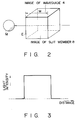
- a cubic measuring volume E is created around the point P.
- the distribution of light in the measuring volume E is uniform by virtue of the rectangular waveguide 4.
- the light scattered by the particle M is guided into the optical fiber 9 through the lens 7 and slit member 8. Then, the light is guided into an optical detector 10 having a photomultiplier tube, where it is converted to an electrical signal, i.e., to a scattered light pulse signal S corresponding to the intensity of the scattered light.
- the signal S is supplied to a signal processor 13 via an amplifier 11 and a waveform memory 12.
- V W/T (2) where T represents a period of time required for the particle to pass the measuring volume E.
- An accurate scattered light pulse signal S1 is obtained when a particle M has passed a central area of the measuring volume E.
- a particle M2 (having the same diameter and velocity as the particle M1) has passed a peripheral area of the measuring volume E, a scattered light pulse signal S2 having an intensity lower than that (I max) of the correct signal S1.
- the signal processor 13 determines that the particle M2 is smaller than the particle M1, though they have in fact the same diameter.
- the conventional apparatus is disadvantageous in that its reliability is reduced when it measures a particle which does not pass a central area of the measuring volume.
- the present invention provides apparatus as defined in Claim 1.
- the slit member may be arranged upstream or downstream of the measuring volume E. That is, it may be arranged at the side of the emitting optical system A for emitting light into the measuring volume E, or alternatively at the side of the receiving optical system B for receiving the light having passed the volume E.
- the slit member In the case that the slit member is upstream of the measuring volume E, and since it is made of a partially-permeable film, the light having passed the slit member forms a striped luminous flux and reaches the measuring volume JE.
- the detected scattered light is converted to a voltage signal to obtain a scattered light pulse signal.
- This pulse signal is compared with a predetermined reference signal by means of the determining and selecting means, and is selected when it corresponds to the reference signal.
- the reference signal corresponds to the pulse waveform and pulse number of the scattered light pulse signal obtained when a particle has passed a central area of the measuring volume E.
- the detected scattered light pulse signal is selected as calculation data. On the other hand, if it is determined that the particle has not passed the central area, the pulse signal is not used.
- the pulse signal contains the pulse number N of each pulse, the waveform of each pulse, and the frequency f of the pulse array.
- the diameter D of a particle is calculated from the pulse number N and a pulse height I. Further, the velocity V of the particle is obtained from the frequency f of the pulse array and the width W of the measuring volume E.
- the scattered light pulse signal of a particle having passed the central area of the measuring volume E is used as calculation data, which enables an accurate measurement of a particle diameter, and also enables an accurate measurement of a particle velocity even in a case where the pulse signal has an undesirable S/N ratio.
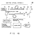
- a particle diameter/velocity measuring apparatus 20 comprises an emitting optical system A, a receiving optical system B, and a processing system C.
- An incoherent light source such as an Xe lamp is used as light source 21 of the system A.
- Light emitted from the light source 21 is guided into an optical fiber 40 through a lens 22, and then guided to an area in the vicinity of a measuring volume P by means of a probe 30.
- the probe 30 consists of rectangular waveguides 34, lens 36 and 38, a mirror 37, a slit member 50, and a protecting case 31 containing those components 34, 36, 38, 37, and 50.
- the protecting case 31 has openings 32 and 33 through which the optical fiber 40 and an optical fiber 41 are inserted.
- the inserted ends of the fiber 40 is connected to the rectangular waveguide 34.
- the lens 36 is provided on the outlet side of the waveguide 34.
- the mirror 37 is located downstream of the lens 36, to thereby reflect light having passed the lens 36.
- the lens 36 and mirror 37 are arranged to cause the light output from the waveguide 34 to converge to a point P in a measuring volume E.
- a desired number of particles M are introduced from a particle supply (not shown) into the measuring volume E at a desired speed in a desired direction.
- the light focused on the point P is guided into a optical fiber 41 through the lens 38 and slit member 50.
- the lens 38 is arranged such that it has a focus thereof positioned on the point P.
- the point P is formed in the measuring volume E.
- an angle ⁇ formed by the optical axes of the emitting optical system A and receiving optical system B is, for example, the angle ⁇ is 90°
- a rectangular parallelepipedic measuring volume is formed around the point P.
- the intersecting angle ⁇ is set at 30°.
- the slit member 50 is arranged at the inlet side end of the optical fiber 41 of the receiving optical system B.
- the slit member 50 (Fig. 10) is formed of a rectangular film which has two strip masks each extending from an end of the film to the other end, and window portions extending alternately and parallel with the masks, and having the same width as the masks. The mask strips interrupt light, while the window portions allow light to pass.
- a light detector 10 incorporated in the processing system C is provided at the outlet side of the optical fiber 41 of the receiving optical system B, and detects light to convert it to a voltage signal.
- the output side of the light detector 10 is connected to the input side of a digital storage oscilloscope 12 via an amplifier 11.
- the output side of the oscilloscope 12 is connected to the input side of a computer 13.
- a reference signal is prestored in the oscilloscope 12.
- the reference signal contains the same pulse waveform and pulse number as those of a scattered light pulse signal obtained when a particle M has passed a central area of the measuring volume E.
- the computer 13 compares a signal by the digital storage oscilloscope 12 with the reference signal stored in the memory, thereby determining whether or not the particle M has passed the central area of the volume E.
- the output side of the computer 13 is connected to a display 14.
- the functions of the rectangular waveguide 34 and the slit member 50 will be explained referring to Fig. 9. If the waveguide 34 is not employed, the light will expand to form a cone, and will have, at the cross section taken along line IX - IX, an intensity showing a Gaussian distribution as indicated by the broken curve line in Fig. 9. If, on the contrary, the waveguide 34 and slit member 50 are employed, the light will pass the courses indicated by the solid lines in Fig. 7 through the waveguide 34, and three light pulses of the same height and of the same width will obtained at the IX - IX cross section, as indicated by the solid lines in Fig. 9.
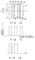
- the measuring volume E will be explained with reference to Fig. 10. That aspect of the volume E which is viewed from the receiving optical system B side appears to have a banded structure, since part of the light is shaded by the slit member 50. That is, the slit member forms two pseudo shading areas (hatched portions) 53 and three fully-permeable areas 54 arranged alternately with the areas 53. The passing course of the particle M in the measuring volume E is perpendicular to the line of the longitudinal direction of the pseudo shading areas 53.
- the particle M to be measured is guided to the measuring volume E, and crosses the two pseudo shading areas 53 and three fully-permeable areas 54.
- a scattered light pulse signal having three pulses of the same width and height is detected by the detector 10, as is shown in Fig. 11.
- This pulse signal correspond to the reference signal prestored in the digital storage oscilloscope 11, and hence are used in the computer 13 as calculation data for obtaining the diameter D and velocity V of the particle M.
- a scattered light pulse signal having three pulses is detected, as is shown in Fig. 13. Since one of the pulses has a width smaller than the others, the signal does not correspond to the reference signal, and is not used as calculation data.
- the present invention only the data which corresponds to the reference signal is selected as calculation data, which enables the apparatus to obtain more reliable measurement results than the conventional apparatus.
- a variation in the pulse width and pulse number of a signal obtained when the particle M passes a peripheral area of the measuring volume E is easily detected, and the signal is omitted in calculation, which makes it possible to obtain an accurate measurement result.
- the masks each have a length shorter than the slit member, and windows at both longitudinal opposite ends.
- the measuring volume E has pseudo shading areas 58, and a fully-permeable area 59 extending over to the longitudinal opposite ends of the pseudo shading areas 58, as is shown in Fig. 14.
- the measuring volume E formed as above when the particle M has passed a peripheral area of the volume E, i.e, when a half of the particle M has passed the volume E, only one of the peaks of the waveform of the particle is measured, so that it is easily determined whether or not the particle has passed a central area of the volume E.
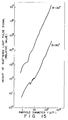
- Fig. 15 is a graph showing the influence of the intersecting angle ⁇ , formed by the optical axes, upon the detection sensitivity in a case where the ratio of the diameter D of the particle M to a predetermined wavelength of light is large.
- the abscissa indicates the particle diameter, while the ordinate indicates the relative height of the scattered light pulse signal.
- the pulse signal height is substantially proportional to a value obtained by squaring the particle diameter.
- the computer 13 calculates the particle diameter. Further, it can be understood from the figure that the height of the scattered light pulse signal is higher and hence its detection accuracy is much higher in a case where the intersecting angle ⁇ is 30° than in a case where it is 90°.
- the measuring apparatus can provide a high measuring accuracy only by incorporating therein the slit member 50 serving as partially-permeable film of the receiving optical system B.
- An apparatus 60 according to the third embodiment is similar to those of the first and second embodiments except in that the slit member 50 serving as partially-permeable film is provided in the emitting optical system A.
- the slit member 50 is provided in contact with the outlet end of the rectangular waveguide 34 of the emitting optical system A.
- the light guided through the optical fiber 40 is transferred in the waveguide 34, as indicated by the solid lines in Fig. 17.
- the measuring volume E is viewed as shown in Fig. 10, from the side of the receiving optical system B.
- the present invention it is determined from the pulse waveform and pulse number of a scattered light pulse signal generated when a particle has passed the measuring volume, whether or not the particle has passed a central area of the measuring volume E. Then, only the data obtained when the particle has passed the central area is selected as calculation data, which enables the diameter and velocity of the particle to be measured with high accuracy.
Landscapes
- Chemical & Material Sciences (AREA)
- Physics & Mathematics (AREA)
- General Physics & Mathematics (AREA)
- Dispersion Chemistry (AREA)
- Health & Medical Sciences (AREA)
- Life Sciences & Earth Sciences (AREA)
- Analytical Chemistry (AREA)
- Biochemistry (AREA)
- General Health & Medical Sciences (AREA)
- Immunology (AREA)
- Pathology (AREA)
- Length Measuring Devices By Optical Means (AREA)
Claims (6)
- Vorrichtung zum Messen des Durchmessers und der Geschwindigkeit eines Teilchens (M), die folgendes umfaßt:
eine Lichtquelle (21);
ein Lichtübertragungssystem (A) zum Leiten des von der Lichtquelle (21) emittierten Lichts in ein Meßvolumen (E);
ein Schlitzglied (50) zum teilweisen Durchlassen des Lichts bevor es das Meßvolumen (E) erreicht oder nachdem es dasselbe durchläuft;
eine Detektionseinrichtung für Streulicht-Impulssignale (10) zum Detektieren des vom durch das Meßvolumen (E) laufenden Teilchen (M) gestreuten Lichts als ein Impulssignal;
eine Bestimmungs- und Auswahleinrichtung (12) zur Bestimmung, ob die Impulswellenform und die Impulsanzahl eines durch die Detektionseinrichtung (10) detektierten Streulicht-Impulssignals normal sind oder nicht, und dann zum Auswahlen des Streulicht-Impulssignals, wenn es als normal bestimmt wird; und
eine Berechnungseinrichtung (13) zur Berechnung wenigstens eines von Durchmesser und Geschwindigkeit des Teilchens (M) auf der Grundlage des ausgewählten Signals;
dadurch gekennzeichnet, daß:
die Lichtquelle (21) inkohärentes Licht emittiert;
das Lichtübertragungssystem (A) einen rechteckigen Wellenleiter (34) zum Leiten des von der Lichtquelle (21) emittierten Lichts in das Meßvolumen (E) besitzt;
das Schlitzglied (50) aus einem teilweise durchlässigen Film besteht; und
das Schlitzglied (50) sich im Lichtübertragungssystem (A) auf dem optischen Weg an der Austrittsseite des rechteckigen Wellenleiters (34) befindet und eine Struktur hat, die in einem mittigen Bereich des Meßvolumens (E) wenigstens zwei lichtabgeschirmte Bereiche (53, 58) bildet;
die Bestimmungs- und Auswahleinrichtung (12) bestimmt, ob die Impulswellenform und die Impulsanzahl eines von der Detektionseinrichtung (10) detektierten Streulicht-Impulssignals normal sind oder nicht, falls sie in Übereinstimmung mit dem Ergebnis sind, das beim Durchgang eines Teilchens durch beide oder alle lichtabgeschirmten Bereiche (53, 58) erwartet wird. - Vorrichtung gemäß Anspruch 1, worin das Schlitzglied (50) so geformt ist, daß sich im Meßvolumen (E) von dessen einem Ende zu dessen anderen Ende eine Vielzahl von Schattenbereichen (53) erstrecken, von denen jeder eine vorherbestimmte Breite hat.
- Vorrichtung gemäß Anspruch 1, dadurch gekennzeichnet, daß das Schlitzglied (50) so geformt ist, daß sich im Meßvolumen (E) ausgenommen dessen Randbereich (59) eine Vielzahl von Schattenbereichen (58) erstrecken, von denen jeder eine vorherbestimmte Breite hat.
- Vorrichtung gemaß Anspruch 1, 2 oder 3, die weiterhin eine zwischen dem Meßvolumen (E) und der Detektionseinrichtung für Streulicht-Impulssignale (10) eingefügte optische Faser (41) umfaßt, und worin das Schlitzglied (50) auf der Einlaßseite der optischen Faser (41) bereitgestellt wird.
- Vorrichtung gemäß jeglichem vorangehenden Anspruch, worin das Schlitzglied (50) an der Auslaßseite des rechteckigen Wellenleiters (34) bereitgestellt wird.
- Vorrichtung gemäß jeglichem vorangehenden Anspruch, worin die Bestimmungs- und Auswahleinrichtung (12) ein Bezugssignal zur Bestimmung, ob das Streulicht-Impulssignal normal ist, vorspeichert.
Applications Claiming Priority (2)
| Application Number | Priority Date | Filing Date | Title |
|---|---|---|---|
| JP2280575A JPH04157339A (ja) | 1990-10-20 | 1990-10-20 | 粒径・速度測定装置 |
| JP280575/90 | 1990-10-20 |
Publications (3)
| Publication Number | Publication Date |
|---|---|
| EP0487189A2 EP0487189A2 (de) | 1992-05-27 |
| EP0487189A3 EP0487189A3 (en) | 1992-12-02 |
| EP0487189B1 true EP0487189B1 (de) | 1995-04-05 |
Family
ID=17626945
Family Applications (1)
| Application Number | Title | Priority Date | Filing Date |
|---|---|---|---|
| EP91307676A Expired - Lifetime EP0487189B1 (de) | 1990-10-20 | 1991-08-21 | Vorrichtung zur Messung des Durchmessers und der Geschwindigkeit eines Teilchens |
Country Status (3)
| Country | Link |
|---|---|
| EP (1) | EP0487189B1 (de) |
| JP (1) | JPH04157339A (de) |
| DE (1) | DE69108682T2 (de) |
Families Citing this family (13)
| Publication number | Priority date | Publication date | Assignee | Title |
|---|---|---|---|---|
| DE4326979C2 (de) * | 1993-08-11 | 1998-02-12 | Dantec Invent Measurement Tech | Laser-Doppler-Gerät sowie Verfahren zum Betreiben eines solchen Gerätes |
| JP4563600B2 (ja) * | 2001-03-01 | 2010-10-13 | 大塚電子株式会社 | 光散乱測定プローブ |
| JP2003121337A (ja) * | 2001-08-07 | 2003-04-23 | Sysmex Corp | 粒子径の計測装置と計測方法 |
| DE10202999B4 (de) * | 2002-01-26 | 2004-04-15 | Palas Gmbh Partikel- Und Lasermesstechnik | Verfahren und Vorrichtung zum Messen der Größenverteilung und Konzentration von Partikeln in einem Fluid |
| JP2004170484A (ja) * | 2002-11-18 | 2004-06-17 | Yuji Matsuura | ビームホモジナイザ |
| GB2422193B (en) * | 2004-12-24 | 2008-07-16 | Campbell Scient Ltd | A weather measurement device for determining the speed in a first direction of hydrometeors |
| US7817254B2 (en) * | 2008-01-30 | 2010-10-19 | Palo Alto Research Center Incorporated | Obtaining information from time variation of sensing results |
| DE102009030691A1 (de) * | 2009-06-26 | 2010-12-30 | Fraunhofer-Gesellschaft zur Förderung der angewandten Forschung e.V. | Partikelmesskopf, Partikelmessvorrichtung und Partikelmessverfahren zur Messung der Partikelfracht von Fluiden |
| FR3027107B1 (fr) * | 2014-10-09 | 2019-09-13 | Espci Paristech | Methode et dispositif de detection optique de nanoparticules dans un echantillon fluide |
| CN111089986A (zh) * | 2019-11-25 | 2020-05-01 | 中国航空工业集团公司洛阳电光设备研究所 | 一种基于光纤传像束的粒子图像测速装置 |
| CN111811995B (zh) * | 2020-07-17 | 2022-04-15 | 中国地质大学(北京) | 模拟粗糙单-交叉裂隙多相渗流的可视化试验方法及系统 |
| CN112014272B (zh) * | 2020-08-10 | 2021-07-23 | 北京大学 | 一种纳米粒子传感器及纳米粒子检测方法 |
| CN114441418A (zh) * | 2022-01-28 | 2022-05-06 | 天津凌视科技有限公司 | 用于高速流动微粒的成像系统、成像方法及可读存储介质 |
Family Cites Families (1)
| Publication number | Priority date | Publication date | Assignee | Title |
|---|---|---|---|---|
| US4251733A (en) * | 1978-06-29 | 1981-02-17 | Hirleman Jr Edwin D | Technique for simultaneous particle size and velocity measurement |
-
1990
- 1990-10-20 JP JP2280575A patent/JPH04157339A/ja active Pending
-
1991
- 1991-08-21 DE DE69108682T patent/DE69108682T2/de not_active Expired - Fee Related
- 1991-08-21 EP EP91307676A patent/EP0487189B1/de not_active Expired - Lifetime
Non-Patent Citations (1)
| Title |
|---|
| JOURNAL OF PHYSICS E: SCIENTIFIC INSTRUMENTS vol. 11, no. 7, July 1978, ENGLAND, pp. 639-642 ; G. WIGLEY: 'The sizing of large droplets by laser anemometry' * |
Also Published As
| Publication number | Publication date |
|---|---|
| EP0487189A2 (de) | 1992-05-27 |
| DE69108682D1 (de) | 1995-05-11 |
| EP0487189A3 (en) | 1992-12-02 |
| DE69108682T2 (de) | 1995-08-17 |
| JPH04157339A (ja) | 1992-05-29 |
Similar Documents
| Publication | Publication Date | Title |
|---|---|---|
| US5999256A (en) | Particle measurement system | |
| US4480483A (en) | Acousto-optical ultrasonic flowmeter | |
| US4251733A (en) | Technique for simultaneous particle size and velocity measurement | |
| US4537507A (en) | Dual beam maximum intensity laser sizing system | |
| US4148585A (en) | Three dimensional laser Doppler velocimeter | |
| JP2641927B2 (ja) | 微粒子測定装置 | |
| Bauckhage | The Phase‐Doppler‐Difference‐Method, a New Laser‐Doppler Technique for Simultaneous Size and Velocity Measurements. Part 1: Description of the method | |
| EP0487189A2 (de) | Vorrichtung zur Messung des Durchmessers und der Geschwindigkeit eines Teilchens | |
| EP0447529A4 (en) | Method for measuring the size and velocity of spherical particles using the phase and intensity of scattered light | |
| EP0703445A2 (de) | Verfahren und Vorrichtung zur Messung der Konzentration von absorbierenden Bestandteilen in einem streuenden Medium | |
| US4641962A (en) | Aberration measuring method | |
| US4737648A (en) | Apparatus for detecting fibrous particle sizes by detecting scattered light at different angles | |
| US5793478A (en) | Apparatus for measuring particle properties | |
| US6841778B1 (en) | Method and apparatus for measuring particulates in vehicle emissions | |
| EP0528802B1 (de) | Geteilter fluss für gleichmässigen multidetektornachweis | |
| JPS61139747A (ja) | 粒子解析装置 | |
| EP0167272A2 (de) | Apparat zur Messung der Abmessungen von Teilchen | |
| GB2202626A (en) | Particle size measuring apparatus | |
| EP0259036A3 (de) | Apparat zur Qualitätsprüfung | |
| EP0594327A1 (de) | Kapillardetektorzelle mit abbildenden Elementen zur Optimierung der Empfindlichkeit | |
| US3548655A (en) | Measurement of fluid or surface velocities | |
| US5751410A (en) | Method for measuring flow vectors in gas flows | |
| DE69119296T2 (de) | Dopplergeschwindigkeitsmesser und Gerät unter Verwendung desselben | |
| EP1354187A2 (de) | Teilchensicht- und konzentrationssensor mit einem hohlen geformten strahl | |
| JP4777360B2 (ja) | 走行時間光学速度計 |
Legal Events
| Date | Code | Title | Description |
|---|---|---|---|
| PUAI | Public reference made under article 153(3) epc to a published international application that has entered the european phase |
Free format text: ORIGINAL CODE: 0009012 |
|
| 17P | Request for examination filed |
Effective date: 19910918 |
|
| AK | Designated contracting states |
Kind code of ref document: A2 Designated state(s): DE GB |
|
| PUAL | Search report despatched |
Free format text: ORIGINAL CODE: 0009013 |
|
| AK | Designated contracting states |
Kind code of ref document: A3 Designated state(s): DE GB |
|
| 17Q | First examination report despatched |
Effective date: 19940118 |
|
| GRAA | (expected) grant |
Free format text: ORIGINAL CODE: 0009210 |
|
| AK | Designated contracting states |
Kind code of ref document: B1 Designated state(s): DE GB |
|
| REF | Corresponds to: |
Ref document number: 69108682 Country of ref document: DE Date of ref document: 19950511 |
|
| PLBE | No opposition filed within time limit |
Free format text: ORIGINAL CODE: 0009261 |
|
| STAA | Information on the status of an ep patent application or granted ep patent |
Free format text: STATUS: NO OPPOSITION FILED WITHIN TIME LIMIT |
|
| 26N | No opposition filed | ||
| REG | Reference to a national code |
Ref country code: GB Ref legal event code: 746 Effective date: 19981023 |
|
| PGFP | Annual fee paid to national office [announced via postgrant information from national office to epo] |
Ref country code: GB Payment date: 19990818 Year of fee payment: 9 |
|
| PGFP | Annual fee paid to national office [announced via postgrant information from national office to epo] |
Ref country code: DE Payment date: 19990823 Year of fee payment: 9 |
|
| PG25 | Lapsed in a contracting state [announced via postgrant information from national office to epo] |
Ref country code: GB Free format text: LAPSE BECAUSE OF NON-PAYMENT OF DUE FEES Effective date: 20000821 |
|
| GBPC | Gb: european patent ceased through non-payment of renewal fee |
Effective date: 20000821 |
|
| PG25 | Lapsed in a contracting state [announced via postgrant information from national office to epo] |
Ref country code: DE Free format text: LAPSE BECAUSE OF NON-PAYMENT OF DUE FEES Effective date: 20010501 |