EP0487112A1 - Secondary air supply system for engine unit - Google Patents
Secondary air supply system for engine unit Download PDFInfo
- Publication number
- EP0487112A1 EP0487112A1 EP91119988A EP91119988A EP0487112A1 EP 0487112 A1 EP0487112 A1 EP 0487112A1 EP 91119988 A EP91119988 A EP 91119988A EP 91119988 A EP91119988 A EP 91119988A EP 0487112 A1 EP0487112 A1 EP 0487112A1
- Authority
- EP
- European Patent Office
- Prior art keywords
- chamber
- diaphragm
- pump
- secondary air
- air
- Prior art date
- Legal status (The legal status is an assumption and is not a legal conclusion. Google has not performed a legal analysis and makes no representation as to the accuracy of the status listed.)
- Granted
Links
Images

Classifications
-
- F—MECHANICAL ENGINEERING; LIGHTING; HEATING; WEAPONS; BLASTING
- F01—MACHINES OR ENGINES IN GENERAL; ENGINE PLANTS IN GENERAL; STEAM ENGINES
- F01N—GAS-FLOW SILENCERS OR EXHAUST APPARATUS FOR MACHINES OR ENGINES IN GENERAL; GAS-FLOW SILENCERS OR EXHAUST APPARATUS FOR INTERNAL COMBUSTION ENGINES
- F01N3/00—Exhaust or silencing apparatus having means for purifying, rendering innocuous, or otherwise treating exhaust
- F01N3/08—Exhaust or silencing apparatus having means for purifying, rendering innocuous, or otherwise treating exhaust for rendering innocuous
- F01N3/10—Exhaust or silencing apparatus having means for purifying, rendering innocuous, or otherwise treating exhaust for rendering innocuous by thermal or catalytic conversion of noxious components of exhaust
- F01N3/24—Exhaust or silencing apparatus having means for purifying, rendering innocuous, or otherwise treating exhaust for rendering innocuous by thermal or catalytic conversion of noxious components of exhaust characterised by constructional aspects of converting apparatus
- F01N3/30—Arrangements for supply of additional air
- F01N3/32—Arrangements for supply of additional air using air pump
-
- F—MECHANICAL ENGINEERING; LIGHTING; HEATING; WEAPONS; BLASTING
- F02—COMBUSTION ENGINES; HOT-GAS OR COMBUSTION-PRODUCT ENGINE PLANTS
- F02M—SUPPLYING COMBUSTION ENGINES IN GENERAL WITH COMBUSTIBLE MIXTURES OR CONSTITUENTS THEREOF
- F02M35/00—Combustion-air cleaners, air intakes, intake silencers, or induction systems specially adapted for, or arranged on, internal-combustion engines
-
- F—MECHANICAL ENGINEERING; LIGHTING; HEATING; WEAPONS; BLASTING
- F02—COMBUSTION ENGINES; HOT-GAS OR COMBUSTION-PRODUCT ENGINE PLANTS
- F02B—INTERNAL-COMBUSTION PISTON ENGINES; COMBUSTION ENGINES IN GENERAL
- F02B75/00—Other engines
- F02B75/02—Engines characterised by their cycles, e.g. six-stroke
- F02B2075/022—Engines characterised by their cycles, e.g. six-stroke having less than six strokes per cycle
- F02B2075/025—Engines characterised by their cycles, e.g. six-stroke having less than six strokes per cycle two
-
- Y—GENERAL TAGGING OF NEW TECHNOLOGICAL DEVELOPMENTS; GENERAL TAGGING OF CROSS-SECTIONAL TECHNOLOGIES SPANNING OVER SEVERAL SECTIONS OF THE IPC; TECHNICAL SUBJECTS COVERED BY FORMER USPC CROSS-REFERENCE ART COLLECTIONS [XRACs] AND DIGESTS
- Y02—TECHNOLOGIES OR APPLICATIONS FOR MITIGATION OR ADAPTATION AGAINST CLIMATE CHANGE
- Y02A—TECHNOLOGIES FOR ADAPTATION TO CLIMATE CHANGE
- Y02A50/00—TECHNOLOGIES FOR ADAPTATION TO CLIMATE CHANGE in human health protection, e.g. against extreme weather
- Y02A50/20—Air quality improvement or preservation, e.g. vehicle emission control or emission reduction by using catalytic converters
-
- Y—GENERAL TAGGING OF NEW TECHNOLOGICAL DEVELOPMENTS; GENERAL TAGGING OF CROSS-SECTIONAL TECHNOLOGIES SPANNING OVER SEVERAL SECTIONS OF THE IPC; TECHNICAL SUBJECTS COVERED BY FORMER USPC CROSS-REFERENCE ART COLLECTIONS [XRACs] AND DIGESTS
- Y02—TECHNOLOGIES OR APPLICATIONS FOR MITIGATION OR ADAPTATION AGAINST CLIMATE CHANGE
- Y02T—CLIMATE CHANGE MITIGATION TECHNOLOGIES RELATED TO TRANSPORTATION
- Y02T10/00—Road transport of goods or passengers
- Y02T10/10—Internal combustion engine [ICE] based vehicles
- Y02T10/12—Improving ICE efficiencies
Definitions
- the present invention relates to a secondary air supply system for an engine unit, particularly for a two-stroke cycle engine of a vehicle.
- a piston of a piston-cylinder assembly performs a reciprocal motion in a cylinder and an exhaust gas exhausted from an engine is fed into an exhaust pipe to which a catalyst is provided for the purification of the exhaust gas through an oxidation reaction.
- This oxidation reaction is carried out by supplying air into the exhaust pipe and this air is called secondary air for the engine unit in comparison with an air to be mixed with a fuel as a primary air.
- the secondary air is generally fed into the exhaust pipe through a one-way valve by the utilization of a pressure variation, i.e. pulsation, of the exhaust gas in the exhaust pipe to thereby suck the secondary air thereinto, or the secondary air is supplied by the actuation of a pump means attached to the engine unit.
- such secondary air supply system can be constructed relatively easily with no increased cost, but in the emplyment of such type structure, less intake air is fed at a time of an engine high power operation period, i.e. engine high revolution speed operation, at which voluminous exhaust gas is discharged, resulting in insufficient purification of the engine exhaust gas.
- an object of the present invention is to substantially eliminate defects or drawbacks encountered in the prior art and to provide a secondary air supply system for an engine unit of a vehicle capable of possibly reducing a power output loss of the engine and capable of supplying the secondary air into an exhaust pipe by an amount in proportion to an exhaust gas from the engine unit, particularly for a two-stroke cycle engine unit of a vehicle.
- a secondary air supply system of a vehicle including an engine unit having a crank chamber and being operatively connected to an air cleaner and an exhaust system including an exhaust pipe, comprising a diaphragm pump means provided with an inner chamber means and having an air inlet port and an air outlet port both being communicated with the inner chamber means, a diaphragm disposed in the chamber means to divide the inner chamber means into a diaphragm chamber and a pump chamber, a first hose connecting the air inlet port and the air clearner to introduce a secondary air from the air cleaner into the pump chamber of the diaphragm pump means through the inlet port, a second hose connecting the air outlet port and the exhaust pipe to supply the secondary air from the diaphragm pump means into the exhaust pipe through the outlet port, and a third hose connecting the diaphragm chamber of the diaphragm pump means and the crank chamber of the engine unit, wherein the secondary air is supplied into the exhaust pipe through the diaphragm
- a valve assembly is further disposed in the pump chamber for allowing the secondary air introduced into the pump chamber to flow uni-directionaly from the inlet port to the outlet port.
- the pump chamber is composed of a first pump chamber communicated with the inlet port, a second pump chamber communicated with the outlet port and a common passage chamber connecting the first and second pump chambers and wherein the valve assembly comprises a first one-way valve disposed in the first pump chamber and a second one-way valve disposed in the second pump chamber, the first one-way valve being operated to introduce the secondary air into the first pump chamber when the diaphragm is displaced so as to increase an inner volume of the pump chamber and the second one-way valve being operated to discharge the secondary air from the second pump chamber when the diaphragm is displaced so as to decrease the inner volume of the pump chamber.
- the secondary air supply system is preferably functioned when used for the two-stroke cycle engine unit.
- the pressure variation caused in the crank chamber of the engine unit by the reciprocation of the piston is transferred to the diaphragm pump device through the connection hose and the diaphragm disposed in the diaphragm chamber of the pump device is oscillated.
- the diaphragm is oscillated thereby to vary the inner volume of the pump chamber of the pump device. Accordingly, in proportion to the magnitude and the frequency of the pressure variation, the secondary air is supplied in a regulated manner into the exhaust pipe through the diaphragm pump device of the present invention.
- a two-stroke cycle engine unit 7 is provided with a combustion chamber, not shown, into which an air is supplied from an air cleaner 11.
- the engine unit 7 is provided with an exhaust gas port, not shown, through which an exhaust pipe 14 is connected.
- the exhaust pipe 14 is communicated with an expansion chamber 15, which is then communicated with a muffler 17.
- the exhaust pipe 14 has a portion, located in the expansion chamber 15, to which a catalyst 16 is disposed for performing an oxidation reaction for the purification of the exhaust gas.
- the air introduced from the air cleaner 11 into the combustion chamber of the engine unit so-called primary air, is mixed with a fuel therein and the mixture is then exploded by the actuation of piston-cylinder assembly incorporated in the engine unit.
- the exhaust gas caused by the explosion is exhausted into the exhaust pipe 14 through the engine exhaust port, and the exhaust gas is then discharged externally through the muffler 17 after the silencing operation.
- connection means having suitable flexibility and rigidity such as hose means 10 and 13, and a diaphragm pump 1 is incorporated to this connection means.
- hose means 10 and 13 a diaphragm pump 1 is incorporated to this connection means.
- one hose 10 extending from the air cleaner 11 is connected to an inlet port 9 of the diaphragm pump 1 at one end thereof and the other hose 13 has one end connected to an outlet port 12 of the diaphragm pump 1 and the other end connected to the exhaust pipe 14.
- the diaphragm pump 1 is further connected to a crank chamber 8 of the two-stroke cycle engine 7 through a hose 6 as best shown in Fig. 1.
- the connection of the hose 6 to the engine unit 7 can be easily made by preliminarily forming a connection hole to the engine crank chamber 8 and, in actual, the connection is carried out by fixing one end of the hose 6 to the hole of the engine unit by a proper fastening means 19 of known structure.
- the diaphragm pump 1 is supported by the air cleaner 11 and the exhaust pipe through the hoses 10 and 13 having proper flexibility and rigidity, the diaphragm pump 1 can be itself easily secured to a body of an automobile such as frame member 18 thereof.
- these hoses 10 and 13 may be connected to the inlet and outlet ports 9 and 12 through connection fittings, or nozzle members for the connection of these hoses 10 and 13 may be formed to the inlet and outlet ports 9 and 12.
- the structure of the diaphragm pump 1 has a structure as shown in Fig. 4 as a longitudinal section thereof.
- the diaphragm pump 1 comprises a pump housing 20 in which an inner chamber means is defined.
- the inner chamber means is composed of a first pump chamber 4a, a second pump chamber 4b and a common chamber which communicates the first and second pump chambers 4a and 4b, and the common chamber is divided into a diaphragm chamber 3 and a passage chamber 4c as a portion of the pump chamber, which communicates the first and second pump chambers 4a and 4b, by means of a diaphragm 2 which is made of a thin metal film, for example.
- One-way valves 5a and 5b are incorporated in the inner chamber means at portions communicating the first and second pump chambers 4a and 4b with the passage chamber 4c.
- the first pump chamber 4a is communicated with the inlet port 9 to which the hose 10 is connected and the second pump chamber 4b is also communicated with the outlet port 12 to which the hose 13 is connected.
- the diaphragm chamber 3 is communicated with the crank chamber 8 through the hose 6.
- Reference numeral 21 denotes a gasket.
- the air i.e. secondary air form the air cleaner 11 is introduced into the first pump chamber 4a through the hose 10 and the inlet port 9 and is discharged towards the exhaust pipe 14 through, in order, the first one-way valve 5a, the passage chamber 4c, the second one-way valve 5b, the second pump chamber 4b, the outlet port 12 and the hose 13.
- the diaphragm 2 is oscillated because this pressure variation is transferred to the diaphragm chamber 3 through the hose 6.
- the volume of the passage chamber 4c i.e. the pump chamber, varies.
- the oscillation of the diaphragm 2 becomes violent in proportion to the increasing of the engine revolution speed and, hence, the amount of the exhaust gas. Accordingly, the air supply amount from the air cleaner 11 into the exhaust pipe 14 can be precisely regulated in proportion to the engine revolution speed, that is, in accordance with the amount of the exhaust gas.
Abstract

Description
- The present invention relates to a secondary air supply system for an engine unit, particularly for a two-stroke cycle engine of a vehicle.
- In a known four- or two-stroke cycle engine unit of a vehicle such as an automobile or motorcycle in which a piston of a piston-cylinder assembly performs a reciprocal motion in a cylinder and an exhaust gas exhausted from an engine is fed into an exhaust pipe to which a catalyst is provided for the purification of the exhaust gas through an oxidation reaction. This oxidation reaction is carried out by supplying air into the exhaust pipe and this air is called secondary air for the engine unit in comparison with an air to be mixed with a fuel as a primary air. The secondary air is generally fed into the exhaust pipe through a one-way valve by the utilization of a pressure variation, i.e. pulsation, of the exhaust gas in the exhaust pipe to thereby suck the secondary air thereinto, or the secondary air is supplied by the actuation of a pump means attached to the engine unit.
- In the former type, in which the one-way valve is incorporated, such secondary air supply system can be constructed relatively easily with no increased cost, but in the emplyment of such type structure, less intake air is fed at a time of an engine high power operation period, i.e. engine high revolution speed operation, at which voluminous exhaust gas is discharged, resulting in insufficient purification of the engine exhaust gas.
- In the latter type, in which a pump means is employed, it may be possible to supply the secondary air in proportion to the engine exhaust gas amount, but there will cause an output power loss of the engine and the mounting of such pump means requires modification or design change of an existing exhaust gas exhausting unit.
- Accordingly, an object of the present invention is to substantially eliminate defects or drawbacks encountered in the prior art and to provide a secondary air supply system for an engine unit of a vehicle capable of possibly reducing a power output loss of the engine and capable of supplying the secondary air into an exhaust pipe by an amount in proportion to an exhaust gas from the engine unit, particularly for a two-stroke cycle engine unit of a vehicle.
- This and other object can be achieved according to the present invention by providing a secondary air supply system of a vehicle including an engine unit having a crank chamber and being operatively connected to an air cleaner and an exhaust system including an exhaust pipe, comprising a diaphragm pump means provided with an inner chamber means and having an air inlet port and an air outlet port both being communicated with the inner chamber means, a diaphragm disposed in the chamber means to divide the inner chamber means into a diaphragm chamber and a pump chamber, a first hose connecting the air inlet port and the air clearner to introduce a secondary air from the air cleaner into the pump chamber of the diaphragm pump means through the inlet port, a second hose connecting the air outlet port and the exhaust pipe to supply the secondary air from the diaphragm pump means into the exhaust pipe through the outlet port, and a third hose connecting the diaphragm chamber of the diaphragm pump means and the crank chamber of the engine unit, wherein the secondary air is supplied into the exhaust pipe through the diaphragm pump by an amount in proportion to an oscillation of the diaphragm caused in accordance with a pressure variation in the crank chamber caused in proportion to an engine revolution speed.
- In a preferred embodiment, a valve assembly is further disposed in the pump chamber for allowing the secondary air introduced into the pump chamber to flow uni-directionaly from the inlet port to the outlet port. The pump chamber is composed of a first pump chamber communicated with the inlet port, a second pump chamber communicated with the outlet port and a common passage chamber connecting the first and second pump chambers and wherein the valve assembly comprises a first one-way valve disposed in the first pump chamber and a second one-way valve disposed in the second pump chamber, the first one-way valve being operated to introduce the secondary air into the first pump chamber when the diaphragm is displaced so as to increase an inner volume of the pump chamber and the second one-way valve being operated to discharge the secondary air from the second pump chamber when the diaphragm is displaced so as to decrease the inner volume of the pump chamber.
- The secondary air supply system is preferably functioned when used for the two-stroke cycle engine unit.
- According to the secondary air supply system for the engine unit of the characters described above, the pressure variation caused in the crank chamber of the engine unit by the reciprocation of the piston. This pressure variation is transferred to the diaphragm pump device through the connection hose and the diaphragm disposed in the diaphragm chamber of the pump device is oscillated. In proportion to the magnitude of the pressure variation, the diaphragm is oscillated thereby to vary the inner volume of the pump chamber of the pump device. Accordingly, in proportion to the magnitude and the frequency of the pressure variation, the secondary air is supplied in a regulated manner into the exhaust pipe through the diaphragm pump device of the present invention.
- For a better understanding of the present invention and to show how the same is carried out, reference will be first made, by way of a preferred embodiment, to the accompanying drawings, in which:
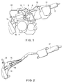
- Fig. 1 is a schematic side view of an exhaust system in association with a two-stroke cycle engine unit to whcih a secondary air supply system according to the present invention is applied;
- Fig. 2 is a schematic view, partially in section, of the exhaust system of Fig. 1;
- Fig. 3 is a side view, in an enlarged scale, of the secondary air supply system shown in Fig. 1 according to one embodiment of the present invention; and
- Fig. 4 is a sectional view of a diaphragm pump incorporated in the secondary air supply system shown in Fig. 3.
- First, referring to Fig. 1, a two-stroke
cycle engine unit 7 is provided with a combustion chamber, not shown, into which an air is supplied from anair cleaner 11. Theengine unit 7 is provided with an exhaust gas port, not shown, through which anexhaust pipe 14 is connected. As shown in Fig. 2, theexhaust pipe 14 is communicated with anexpansion chamber 15, which is then communicated with amuffler 17. Theexhaust pipe 14 has a portion, located in theexpansion chamber 15, to which acatalyst 16 is disposed for performing an oxidation reaction for the purification of the exhaust gas. - The air introduced from the
air cleaner 11 into the combustion chamber of the engine unit, so-called primary air, is mixed with a fuel therein and the mixture is then exploded by the actuation of piston-cylinder assembly incorporated in the engine unit. The exhaust gas caused by the explosion is exhausted into theexhaust pipe 14 through the engine exhaust port, and the exhaust gas is then discharged externally through themuffler 17 after the silencing operation. - In the above structure, the
air cleaner 11 is communicated with theexhaust pipe 14 through connection means having suitable flexibility and rigidity such as hose means 10 and 13, and adiaphragm pump 1 is incorporated to this connection means. Namely, as shown in Fig. 1, onehose 10 extending from theair cleaner 11 is connected to aninlet port 9 of thediaphragm pump 1 at one end thereof and theother hose 13 has one end connected to anoutlet port 12 of thediaphragm pump 1 and the other end connected to theexhaust pipe 14. - The
diaphragm pump 1 is further connected to acrank chamber 8 of the two-stroke cycle engine 7 through ahose 6 as best shown in Fig. 1. The connection of thehose 6 to theengine unit 7 can be easily made by preliminarily forming a connection hole to theengine crank chamber 8 and, in actual, the connection is carried out by fixing one end of thehose 6 to the hole of the engine unit by a proper fastening means 19 of known structure. As described above, since thediaphragm pump 1 is supported by theair cleaner 11 and the exhaust pipe through thehoses diaphragm pump 1 can be itself easily secured to a body of an automobile such asframe member 18 thereof. - In preferred modifications, these
hoses outlet ports hoses outlet ports - The structure of the
diaphragm pump 1 has a structure as shown in Fig. 4 as a longitudinal section thereof. - Referring to Fig. 4, the
diaphragm pump 1 comprises apump housing 20 in which an inner chamber means is defined. The inner chamber means is composed of afirst pump chamber 4a, asecond pump chamber 4b and a common chamber which communicates the first andsecond pump chambers second pump chambers diaphragm 2 which is made of a thin metal film, for example. One-way valves second pump chambers first pump chamber 4a is communicated with theinlet port 9 to which thehose 10 is connected and thesecond pump chamber 4b is also communicated with theoutlet port 12 to which thehose 13 is connected. The diaphragm chamber 3 is communicated with thecrank chamber 8 through thehose 6.Reference numeral 21 denotes a gasket. - According to the structure of the
diaphragm pump 1 described above, the air, i.e. secondary air form theair cleaner 11 is introduced into thefirst pump chamber 4a through thehose 10 and theinlet port 9 and is discharged towards theexhaust pipe 14 through, in order, the first one-way valve 5a, the passage chamber 4c, the second one-way valve 5b, thesecond pump chamber 4b, theoutlet port 12 and thehose 13. In this air flow, when the pressure variation is caused in theengine crank chamber 8 due to the explosion of the air-fuel mixture, thediaphragm 2 is oscillated because this pressure variation is transferred to the diaphragm chamber 3 through thehose 6. According to this oscillation of thediaphragm 2, the volume of the passage chamber 4c, i.e. the pump chamber, varies. - When the volume of the pump chamber is increased, that is, with reference to Fig. 4, the
diaphragm 2 is displaced downwardly, the secondary air is sucked into thediaphragm pump 1 through theinlet port 9 and then flows therein through the first one-way valve 5a, and when the volume of the pump chamber is then decreased, that is, thediaphragm 2 is displaced upwardly, the secondary air is exhausted into thehose 13, connected to theexhaust pipe 14, through the second one-way valve 5b and theoutlet port 12. - As described above, the oscillation of the
diaphragm 2 becomes violent in proportion to the increasing of the engine revolution speed and, hence, the amount of the exhaust gas. Accordingly, the air supply amount from theair cleaner 11 into theexhaust pipe 14 can be precisely regulated in proportion to the engine revolution speed, that is, in accordance with the amount of the exhaust gas. - It is easily understood that the present embodiment was described with reference to the two-stroke cycle engine, but it may be applied to a four-stroke cycle engine, though the two-stroke cycle engine being preferred.
Claims (4)
- A secondary air supply system of a vehicle including an engine unit having a crank chamber and being operatively connected to an air cleaner and an exhaust system including an exhaust pipe, comprising:
a diaphragm pump means provided with an inner chamber means and having an air inlet port and an air outlet port both being communicated with the inner chamber means;
a diaphragm disposed in the chamber means to divide the inner chamber means into a diaphragm chamber and a pump chamber;
a first hose means connecting the air inlet port and the air cleaner to introduce a secondary air from the air cleaner into the pump chamber of the diaphragm pump means through the inlet port;
a second hose means connecting the air outlet port and the exhaust pipe to supply the secondary air from the diaphragm pump means into the exhaust pipe through the outlet port;
a third hose means connecting the diaphragm chamber of the diaphragm pump means and the crank chamber of the engine unit;
wherein the secondary air is supplied into the exhaust pipe through the diaphragm pump by an amount in proportion to an oscillation of the diaphragm caused in accordance with a pressure variation in the crank chamber caused in proportion to an engine revolution speed. - A secondary air supply system according to claim 1, further comprising a valve means disposed in the pump chamber for allowing the secondary air introduced into the pump chamber to flow uni-directionaly from the inlet port to the outlet port.
- A secondary air supply system according to claim 1 or 2, wherein the pump chamber is composed of a first pump chamber communicated with the inlet port, a second pump chamber communicated with the outlet port and a common passage chamber connecting the first and second pump chambers and wherein the valve means comprises a first one-way valve disposed in the first pump chamber and a second one-way valve disposed in the second pump chamber, said first one-way valve being operated to introduce the secondary air into the first pump chamber when the diaphragm is displaced so as to increase an inner volume of the pump chamber and said second one-way valve being operated to discharge the secondary air from the second pump chamber when the diaphragm is displaced so as to decrease the inner volume of the pump chamber.
- A secondary air supply system according to claim 1, 2 or 3, wherein the engine unit is a two-stroke cycle engine of a vehicle.
Applications Claiming Priority (2)
| Application Number | Priority Date | Filing Date | Title |
|---|---|---|---|
| JP316046/90 | 1990-11-22 | ||
| JP2316046A JP3008488B2 (en) | 1990-11-22 | 1990-11-22 | Secondary air supply for two-stroke engine |
Publications (2)
| Publication Number | Publication Date |
|---|---|
| EP0487112A1 true EP0487112A1 (en) | 1992-05-27 |
| EP0487112B1 EP0487112B1 (en) | 1995-05-03 |
Family
ID=18072666
Family Applications (1)
| Application Number | Title | Priority Date | Filing Date |
|---|---|---|---|
| EP91119988A Expired - Lifetime EP0487112B1 (en) | 1990-11-22 | 1991-11-22 | Secondary air supply system for engine unit |
Country Status (7)
| Country | Link |
|---|---|
| US (1) | US5197282A (en) |
| EP (1) | EP0487112B1 (en) |
| JP (1) | JP3008488B2 (en) |
| KR (1) | KR940008280B1 (en) |
| AT (1) | ATE122125T1 (en) |
| DE (1) | DE69109449T2 (en) |
| ES (1) | ES2071194T3 (en) |
Cited By (1)
| Publication number | Priority date | Publication date | Assignee | Title |
|---|---|---|---|---|
| ES2195753A1 (en) * | 2000-12-28 | 2003-12-01 | Honda Motor Co Ltd | Air cleaner structure of vehicle |
Families Citing this family (12)
| Publication number | Priority date | Publication date | Assignee | Title |
|---|---|---|---|---|
| US5755095A (en) * | 1996-05-13 | 1998-05-26 | Maurer; Paul S. | Secondary air supply system for internal combustion engines |
| EP0941397A4 (en) | 1996-11-21 | 2001-01-24 | Paul S Maurer | Secondary air supply system for internal combustion engine |
| JP4540762B2 (en) * | 1999-01-18 | 2010-09-08 | 本田技研工業株式会社 | Saddle-type vehicle with exhaust secondary air valve |
| US20060156711A1 (en) * | 2005-01-20 | 2006-07-20 | Carpenter Todd L | Internal combustion engine with secondary air pump for catalyst |
| EP2224121B1 (en) | 2005-10-12 | 2013-03-06 | Kohler Co. | Air cleaner assembly |
| JP2008064068A (en) * | 2006-09-11 | 2008-03-21 | Yamaha Motor Co Ltd | Motorcycle |
| JP4871107B2 (en) * | 2006-12-06 | 2012-02-08 | ヤマハ発動機株式会社 | Saddle riding |
| USD632770S1 (en) | 2008-06-13 | 2011-02-15 | Kohler Co. | Cyclonic air cleaner housing |
| US8808432B2 (en) | 2008-06-13 | 2014-08-19 | Kohler Co. | Cyclonic air cleaner |
| US20110005479A1 (en) * | 2009-07-08 | 2011-01-13 | Briggs & Stratton Corporation | Air injection system for engine exhaust |
| CN111774218A (en) * | 2020-07-30 | 2020-10-16 | 江苏国富氢能技术装备有限公司 | Automatic ink spraying device and spraying process thereof |
| JP2022167313A (en) * | 2021-04-23 | 2022-11-04 | ヤマハ発動機株式会社 | Saddle-riding type vehicle |
Citations (3)
| Publication number | Priority date | Publication date | Assignee | Title |
|---|---|---|---|---|
| US4084373A (en) * | 1976-03-18 | 1978-04-18 | Toyota Jidosha Kogyo Kabushiki Kaisha | Secondary air supply system for internal combustion engines |
| GB1555497A (en) * | 1976-04-15 | 1979-11-14 | Mitsubishi Jidoshakogyo Kk | Air pump system in a reciprocating enegine |
| WO1989009878A1 (en) * | 1988-04-11 | 1989-10-19 | Brunswick Corporation | Fuel puddle bleed shut-off for fuel injected two cycle engine |
Family Cites Families (4)
| Publication number | Priority date | Publication date | Assignee | Title |
|---|---|---|---|---|
| US3106821A (en) * | 1960-11-07 | 1963-10-15 | Thompson Ramo Wooldridge Inc | Automobile engine exhaust system |
| US3672172A (en) * | 1971-03-15 | 1972-06-27 | Gary L Hammond | Simplified supercharged internal combustion engine with emissions control |
| JPS5218519A (en) * | 1975-08-04 | 1977-02-12 | Nissan Motor Co Ltd | Secondary air feeder |
| JPS52102920A (en) * | 1976-02-26 | 1977-08-29 | Toyota Motor Corp | Secondary-air supply system for exhaust gas cleaner |
-
1990
- 1990-11-22 JP JP2316046A patent/JP3008488B2/en not_active Expired - Fee Related
-
1991
- 1991-11-21 US US07/795,816 patent/US5197282A/en not_active Expired - Fee Related
- 1991-11-22 EP EP91119988A patent/EP0487112B1/en not_active Expired - Lifetime
- 1991-11-22 ES ES91119988T patent/ES2071194T3/en not_active Expired - Lifetime
- 1991-11-22 AT AT91119988T patent/ATE122125T1/en not_active IP Right Cessation
- 1991-11-22 KR KR1019910020982A patent/KR940008280B1/en not_active IP Right Cessation
- 1991-11-22 DE DE69109449T patent/DE69109449T2/en not_active Expired - Fee Related
Patent Citations (3)
| Publication number | Priority date | Publication date | Assignee | Title |
|---|---|---|---|---|
| US4084373A (en) * | 1976-03-18 | 1978-04-18 | Toyota Jidosha Kogyo Kabushiki Kaisha | Secondary air supply system for internal combustion engines |
| GB1555497A (en) * | 1976-04-15 | 1979-11-14 | Mitsubishi Jidoshakogyo Kk | Air pump system in a reciprocating enegine |
| WO1989009878A1 (en) * | 1988-04-11 | 1989-10-19 | Brunswick Corporation | Fuel puddle bleed shut-off for fuel injected two cycle engine |
Cited By (1)
| Publication number | Priority date | Publication date | Assignee | Title |
|---|---|---|---|---|
| ES2195753A1 (en) * | 2000-12-28 | 2003-12-01 | Honda Motor Co Ltd | Air cleaner structure of vehicle |
Also Published As
| Publication number | Publication date |
|---|---|
| ATE122125T1 (en) | 1995-05-15 |
| DE69109449T2 (en) | 1995-09-07 |
| JPH04187811A (en) | 1992-07-06 |
| DE69109449D1 (en) | 1995-06-08 |
| JP3008488B2 (en) | 2000-02-14 |
| KR940008280B1 (en) | 1994-09-09 |
| KR920010145A (en) | 1992-06-26 |
| EP0487112B1 (en) | 1995-05-03 |
| US5197282A (en) | 1993-03-30 |
| ES2071194T3 (en) | 1995-06-16 |
Similar Documents
| Publication | Publication Date | Title |
|---|---|---|
| EP0487112A1 (en) | Secondary air supply system for engine unit | |
| US5902971A (en) | Muffler for internal combustion engine | |
| US6216453B1 (en) | Secondary air supply system for internal combustion engine | |
| US5218817A (en) | Method and apparatus of purifying exhaust gas from internal combustion engine | |
| WO1998025013A9 (en) | Secondary air supply system for internal combustion engine | |
| EP0952334A3 (en) | Pneumatically controlled compressed air assisted fuel injection system | |
| US5755095A (en) | Secondary air supply system for internal combustion engines | |
| US6978605B2 (en) | Exhaust emission control system for engine | |
| US3498054A (en) | Exhaust purification | |
| JPH09158722A (en) | Exhaust device for single cylinder internal combustion engine | |
| JPH0634628Y2 (en) | Fluid pump for engine | |
| US4450683A (en) | Exhaust gas cleaning system for internal combustion engines | |
| JPH0122934Y2 (en) | ||
| SU985376A1 (en) | Gaselus engine fuel feed system | |
| JPH08135544A (en) | Idle speed control device of internal combustion engine | |
| US4363296A (en) | Combustion chamber pressure tap | |
| JPS5985414A (en) | Exhaust noise arrester for internal-combustion engine for car | |
| JP2524843Y2 (en) | Fuel pump mounting structure for general-purpose engine | |
| GB2169655A (en) | A system for feeding secondary air to an exhaust manifold of an internal combustion engine | |
| JP3253114B2 (en) | Engine fuel injection structure | |
| SU1746032A1 (en) | Internal combustion engine feed system | |
| JPS56115811A (en) | Catalytic exhaust system of multicylinder internal combustion engine | |
| JPH08135441A (en) | Exhaust device of internal combustion engine | |
| JPS5851125B2 (en) | exhaust pulsating pump | |
| JPH03145512A (en) | Exhaust sound reducing device for engine |
Legal Events
| Date | Code | Title | Description |
|---|---|---|---|
| PUAI | Public reference made under article 153(3) epc to a published international application that has entered the european phase |
Free format text: ORIGINAL CODE: 0009012 |
|
| 17P | Request for examination filed |
Effective date: 19911122 |
|
| AK | Designated contracting states |
Kind code of ref document: A1 Designated state(s): AT CH DE ES IT LI |
|
| 17Q | First examination report despatched |
Effective date: 19930730 |
|
| GRAA | (expected) grant |
Free format text: ORIGINAL CODE: 0009210 |
|
| AK | Designated contracting states |
Kind code of ref document: B1 Designated state(s): AT CH DE ES IT LI |
|
| REF | Corresponds to: |
Ref document number: 122125 Country of ref document: AT Date of ref document: 19950515 Kind code of ref document: T |
|
| REF | Corresponds to: |
Ref document number: 69109449 Country of ref document: DE Date of ref document: 19950608 |
|
| REG | Reference to a national code |
Ref country code: ES Ref legal event code: FG2A Ref document number: 2071194 Country of ref document: ES Kind code of ref document: T3 |
|
| ITF | It: translation for a ep patent filed |
Owner name: STUDIO ING. ALFREDO RAIMONDI |
|
| PLBE | No opposition filed within time limit |
Free format text: ORIGINAL CODE: 0009261 |
|
| STAA | Information on the status of an ep patent application or granted ep patent |
Free format text: STATUS: NO OPPOSITION FILED WITHIN TIME LIMIT |
|
| 26N | No opposition filed | ||
| PGFP | Annual fee paid to national office [announced via postgrant information from national office to epo] |
Ref country code: AT Payment date: 20021113 Year of fee payment: 12 |
|
| PGFP | Annual fee paid to national office [announced via postgrant information from national office to epo] |
Ref country code: ES Payment date: 20021127 Year of fee payment: 12 |
|
| PGFP | Annual fee paid to national office [announced via postgrant information from national office to epo] |
Ref country code: DE Payment date: 20021128 Year of fee payment: 12 |
|
| PGFP | Annual fee paid to national office [announced via postgrant information from national office to epo] |
Ref country code: CH Payment date: 20021129 Year of fee payment: 12 |
|
| PG25 | Lapsed in a contracting state [announced via postgrant information from national office to epo] |
Ref country code: AT Free format text: LAPSE BECAUSE OF NON-PAYMENT OF DUE FEES Effective date: 20031122 |
|
| PG25 | Lapsed in a contracting state [announced via postgrant information from national office to epo] |
Ref country code: ES Free format text: LAPSE BECAUSE OF NON-PAYMENT OF DUE FEES Effective date: 20031124 |
|
| PG25 | Lapsed in a contracting state [announced via postgrant information from national office to epo] |
Ref country code: LI Free format text: LAPSE BECAUSE OF NON-PAYMENT OF DUE FEES Effective date: 20031130 Ref country code: CH Free format text: LAPSE BECAUSE OF NON-PAYMENT OF DUE FEES Effective date: 20031130 |
|
| PG25 | Lapsed in a contracting state [announced via postgrant information from national office to epo] |
Ref country code: DE Free format text: LAPSE BECAUSE OF NON-PAYMENT OF DUE FEES Effective date: 20040602 |
|
| REG | Reference to a national code |
Ref country code: CH Ref legal event code: PL |
|
| REG | Reference to a national code |
Ref country code: ES Ref legal event code: FD2A Effective date: 20031124 |
|
| PG25 | Lapsed in a contracting state [announced via postgrant information from national office to epo] |
Ref country code: IT Free format text: LAPSE BECAUSE OF NON-PAYMENT OF DUE FEES Effective date: 20051122 |