EP0487110A2 - Computer-aided diagnosis system for medical use - Google Patents
Computer-aided diagnosis system for medical use Download PDFInfo
- Publication number
- EP0487110A2 EP0487110A2 EP91119983A EP91119983A EP0487110A2 EP 0487110 A2 EP0487110 A2 EP 0487110A2 EP 91119983 A EP91119983 A EP 91119983A EP 91119983 A EP91119983 A EP 91119983A EP 0487110 A2 EP0487110 A2 EP 0487110A2
- Authority
- EP
- European Patent Office
- Prior art keywords
- data
- cad
- image
- computer
- result
- Prior art date
- Legal status (The legal status is an assumption and is not a legal conclusion. Google has not performed a legal analysis and makes no representation as to the accuracy of the status listed.)
- Granted
Links
- 0 CC*(C)*C(CC(C)(*1)C(CC2CCC2)C2C)C1(C)C2C1(CC)CCC1 Chemical compound CC*(C)*C(CC(C)(*1)C(CC2CCC2)C2C)C1(C)C2C1(CC)CCC1 0.000 description 1
Images


Classifications
-
- A—HUMAN NECESSITIES
- A61—MEDICAL OR VETERINARY SCIENCE; HYGIENE
- A61B—DIAGNOSIS; SURGERY; IDENTIFICATION
- A61B6/00—Apparatus for radiation diagnosis, e.g. combined with radiation therapy equipment
- A61B6/44—Constructional features of apparatus for radiation diagnosis
- A61B6/4494—Means for identifying the diagnostic device
-
- G—PHYSICS
- G16—INFORMATION AND COMMUNICATION TECHNOLOGY [ICT] SPECIALLY ADAPTED FOR SPECIFIC APPLICATION FIELDS
- G16H—HEALTHCARE INFORMATICS, i.e. INFORMATION AND COMMUNICATION TECHNOLOGY [ICT] SPECIALLY ADAPTED FOR THE HANDLING OR PROCESSING OF MEDICAL OR HEALTHCARE DATA
- G16H30/00—ICT specially adapted for the handling or processing of medical images
- G16H30/20—ICT specially adapted for the handling or processing of medical images for handling medical images, e.g. DICOM, HL7 or PACS
-
- G—PHYSICS
- G16—INFORMATION AND COMMUNICATION TECHNOLOGY [ICT] SPECIALLY ADAPTED FOR SPECIFIC APPLICATION FIELDS
- G16H—HEALTHCARE INFORMATICS, i.e. INFORMATION AND COMMUNICATION TECHNOLOGY [ICT] SPECIALLY ADAPTED FOR THE HANDLING OR PROCESSING OF MEDICAL OR HEALTHCARE DATA
- G16H50/00—ICT specially adapted for medical diagnosis, medical simulation or medical data mining; ICT specially adapted for detecting, monitoring or modelling epidemics or pandemics
- G16H50/20—ICT specially adapted for medical diagnosis, medical simulation or medical data mining; ICT specially adapted for detecting, monitoring or modelling epidemics or pandemics for computer-aided diagnosis, e.g. based on medical expert systems
-
- G—PHYSICS
- G16—INFORMATION AND COMMUNICATION TECHNOLOGY [ICT] SPECIALLY ADAPTED FOR SPECIFIC APPLICATION FIELDS
- G16H—HEALTHCARE INFORMATICS, i.e. INFORMATION AND COMMUNICATION TECHNOLOGY [ICT] SPECIALLY ADAPTED FOR THE HANDLING OR PROCESSING OF MEDICAL OR HEALTHCARE DATA
- G16H40/00—ICT specially adapted for the management or administration of healthcare resources or facilities; ICT specially adapted for the management or operation of medical equipment or devices
- G16H40/60—ICT specially adapted for the management or administration of healthcare resources or facilities; ICT specially adapted for the management or operation of medical equipment or devices for the operation of medical equipment or devices
- G16H40/67—ICT specially adapted for the management or administration of healthcare resources or facilities; ICT specially adapted for the management or operation of medical equipment or devices for the operation of medical equipment or devices for remote operation
-
- Y—GENERAL TAGGING OF NEW TECHNOLOGICAL DEVELOPMENTS; GENERAL TAGGING OF CROSS-SECTIONAL TECHNOLOGIES SPANNING OVER SEVERAL SECTIONS OF THE IPC; TECHNICAL SUBJECTS COVERED BY FORMER USPC CROSS-REFERENCE ART COLLECTIONS [XRACs] AND DIGESTS
- Y10—TECHNICAL SUBJECTS COVERED BY FORMER USPC
- Y10S—TECHNICAL SUBJECTS COVERED BY FORMER USPC CROSS-REFERENCE ART COLLECTIONS [XRACs] AND DIGESTS
- Y10S128/00—Surgery
- Y10S128/92—Computer assisted medical diagnostics
- Y10S128/922—Computer assisted medical diagnostics including image analysis
Definitions
- the doctor refers to the output of the CAD system at the time of reading of the medical image to prevent an oversight of a shadow image of the abnormal portion.
- Another object of the present invention is to provide a picture archiving communication system incorporating the computer-aided diagnosis system for medical use and having a high diagnosis precision.
- a computer-aided diagnosis system comprising means for inputting a medical image and attribute data of the medical image, means for storing a plurality of computer-aided diagnosis algorithms, means for selecting, based on the attribute data, an optimum computer-aided diagnosis algorithm suitable for the medical image, means for analyzing the medical image using the optimum computer-aided diagnosis algorithm selected by said selecting means, and means for displaying an analysis result of said analyzing means.
- the CAD is to obtain CAD data, for example, denoting a position of an abnormality in the image, by processing image data using a computer.
- the workstation 14 serves as a section for obtaining the CAD data.
- bit pattern data is written in a location corresponding to the position of abnormality in the image memory 100 (overlay memory) corresponding to the CRT displaying the image. If a plural CAD results are obtained, the above operation is repeated until all the CAD results are read out and written into the overlay memory.
- the data in the image memory 100 (overlay memory) is displayed on the CRT overlapped with the image data.
- the display color of the bit pattern data of the marker is switched between black and white in synchronism with the timer 90.
- the period of switching is 2Hz.
Abstract
Description
- The present invention relates to a computer-aided diagnosis system for medical use, which outputs computer-aided diagnosis data for medical images using a computer.
- Recently, a computer-aided diagnosis system (hereinafter referred to as a CAD system) for medical use has been developed in which the features of medical image data are determined and computer-aided diagnosis data (hereinafter referred to as CAD data) for assisting a doctor are obtained by using a computer. It is, however, cumbersome for a doctor to operate a computer to obtain the CAD data during the diagnosis, resulting in an adverse effect on a reading operation of image in terms of both time and labor. Further, the conventional CAD system itself cannot provide a high precision CAD data required for the diagnosis.
- Examples of such CAD system are disclosed in USP 4,851,984 and USP 4,839,807. The CAD system described in the above USPs comprises means for inputting a medical image, means for analyzing the medical image using a predetermined CAD algorithm, and means for displaying an analysis result.
- The doctor refers to the output of the CAD system at the time of reading of the medical image to prevent an oversight of a shadow image of the abnormal portion.
- To obtain the CAD data, the following proceedings are required. Locations of one type of abnormal shadow images, e.g., an abnormal shadow image of the interstitial lung disease, are detected on a conventional X-ray radiograph and the result of the detection is output. Therefore, the medical image on the X-ray film is digitized. A rib, an object of the analysis, is identified in the medical image. A region of interest (hereinafter referred to as a ROI) is set on the medical image, as described in the USP 4,851,984. The data in the ROI is frequency-analyzed to extract the amount of physical texture of the image. The shadow image is classified into groups based on the amount of physical texture. A display device displays the digital image and the type, degree, and position of the shadow image in an overlapping manner.
- The reading operation by the doctor is to draft the reading report. Before, drafting the report, the doctor refers to the CAD data to prevent an oversight of a shadow image.
- If the doctor needs the CAD data, the above proceedings must be performed. That is, the medical image must be digitized before the CAD system starts to operate. The digitized image is analyzed by the computer using the above proceedings and the analysis result is output to an attached display device. The doctor continues the reading of the image after watching the CAD result.
- The above described CAD system has following drawbacks.
- The same CAD algorithm which is included in the CAD system is applied to the image data regardless of the type of the image. For example, the same CAD algorithm is applied to a conventional X-ray radiograph of chest as well as a CT image. Therefore, an unexpected CAD result is obtained thus lowering the ability of diagnosis.
- The CAD system includes only one CAD algorithm for a given disease. Therefore, it is not possible to obtain a plurality of CAD data for a plurality of diseases. Therefore, if ten diseases are to be detected from one image based on the CAD data, the image data must be input to ten CAD systems and ten CAD data must be output. This increases the time and labor for the CAD operation.
- A time for merely reading the image without outputting the CAD data is about three minutes. A time from requesting a kind of CAD operation to output the CAD data is about two minutes. If the CAD operation is performed during the reading, it takes a long time for reading and a difficulty occurs for the reading.
- The CAD data includes many items, e.g., the position, type, and degree of the abnormality. In the conventional CAD system, all the items of data are output, thereby the output becomes complicate.
- The CAD system does not store the CAD result, therefore, if the CAD operation is requested for the image which has been once analyzed, the same CAD operation is repeated thus wasting the time.
- Meanwhile, a picture archiving communication system (hereinafter referred to as a PACS) for transferring, storing, and displaying the medical images has been developed. In the PACS, digital medical image data archived by modalities including a digitizer and attribute data thereof are transferred via a network and are stored in a large capacity recording means such as an optical disk device. Desired data are retrieved by using a data base system. The image data is transferred to a workstation via the network and is displayed. However, the prior PACS does not function a CAD operation.
- Accordingly, it is an object of the present invention to provide a computer-aided diagnosis system for medical use, which outputs computer-aided diagnosis data with a high precision by a simple operation having no adverse effect on diagnosis made by doctors.
- Another object of the present invention is to provide a picture archiving communication system incorporating the computer-aided diagnosis system for medical use and having a high diagnosis precision.
- According to one aspect of the present invention, there is provided a computer-aided diagnosis system comprising means for inputting a medical image and attribute data of the medical image, means for storing a plurality of computer-aided diagnosis algorithms, means for selecting, based on the attribute data, an optimum computer-aided diagnosis algorithm suitable for the medical image, means for analyzing the medical image using the optimum computer-aided diagnosis algorithm selected by said selecting means, and means for displaying an analysis result of said analyzing means.
- This invention can be more fully understood from the following detailed description when taken in conjunction with the accompanying drawings, in which:
- Fig. 1 is a block diagram showing the arrangement of a first embodiment of a computer-aided diagnosis system for medical use according to the present invention;
- Fig. 2 shows items of examination data;
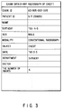
- Fig. 3 shows a practical example of the examination data for a conventional X-ray radiograph of chest;
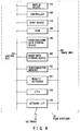
- Fig. 4 is a block diagram showing the arrangement of a film digitizer shown in Fig. 1;
- Fig. 5 shows items of relevant data;
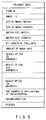
- Fig. 6 shows a practical example of the relevant data;
- Fig. 7 is a view for defining an imaging direction in the conventional X-ray radiography;
- Fig. 8 is a block diagram showing the arrangement of a data base shown in Fig. 1;
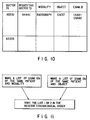
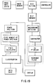
- Fig. 9 shows an examination directory included in a data retrieving device shown in Fig. 8;
- Fig. 10 shows the relationship between a doctor ID and a requesting doctor ID which is used when the image is transferred to a workstation at the time of reading;
- Fig. 11 shows an operation for transferring the images which has been examined to the workstation at the time of reading;
- Fig. 12 is a block diagram showing the arrangement of the workstation shown in Fig. 1;
- Fig. 13 shows an example of the images displayed on the workstation in the PACS at the time of diagnosis of the conventional X-ray radiograph;
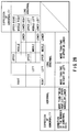
- Fig. 14 shows a CRT image display control table for managing the display of the workstation;
- Fig. 15 shows a table registering the relationship between the name of a CAD algorithm and associated attribute data of the image which is applied with the CAD algorithm;
- Fig. 16 is a view showing a practical example of ROI setting in lungs;
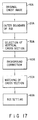
- Fig. 17 is a block diagram schematically showing an algorithm for automatically setting an ROI;
- Fig. 18 is a detailed block diagram for explaining the diagram of Fig. 16;
- Fig. 19 is a block diagram schematically showing an algorithm for obtaining the amount of textures in the ROI;
- Fig. 20 is a flow chart schematically showing an algorithm for determining based on the amount of textures whether the ROI is normal or abnormal;
- Fig. 21 is a block diagram performing the operation shown in Fig. 20;
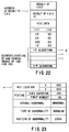
- Fig. 22 shows an example of the data format of a CAD result;
- Fig. 23 is a view showing a practical example of the CAD result data;
- Fig. 24 is a perspective view showing a touch panel as an example of an input device of the workstation;
- Fig. 25 is a view showing a display example of the touch panel;
- Fig. 26 is a view for explaining an example of a schematic naming of abnormal positions;
- Fig. 27 shows a relationship between locations and coordinates of the abnormal positions;
- Fig. 28 shows a table for explaining an example of detailed naming of the abnormal positions;
- Fig. 29 shows an example of a text sentence display;
- Fig. 30 shows an example of marker display;
- Fig. 31 shows an example of detailed CAD display using the marker shown in Fig. 30;
- Fig. 32 shows another example of the marker display;
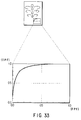
- Fig. 33 shows an ROC curve display as an optional CAD output;
- Fig. 34 shows the data format of a CAD result;
- Fig. 35 shows a practical example of the CAD result;
- Fig. 36 is a block diagram showing the arrangement of a CAD processor included in a second embodiment of a computer-aided diagnosis system for medical use according to the present invention;
- Fig. 37 is a block diagram showing the arrangement of a sound output device as a main part of a third embodiment of the present invention;
- Figs. 38A and 38B show examples of a menu window display according to a seventh embodiment of the present invention;
- Fig. 39 is a block diagram showing the arrangement of a computer-aided diagnosis system according to an eleventh embodiment of the present invention;
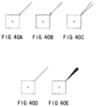
- Figs. 40A to 40E show modifications of marker display according to a twelfth embodiment;
- Figs. 41A to 41F show other modifications of the marker display according to the twelfth embodiment;
- Figs. 42A and 42B show still another modifications of the marker display according to the twelfth embodiment; and
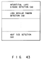
- Fig. 43 shows an example of a table formed of names of algorithms stored in a memory in a seventeenth embodiment of the present invention.
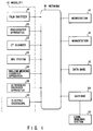
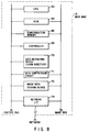
- A preferred embodiment of a computer-aided diagnosis system for medical use according to the present invention will now be described with reference to the accompanying drawings. Though it is possible to embody the CAD system as a stand-alone system, an embodiment of the CAD system incorporated into the PACS will be described. Fig. 1 is a block diagram showing the first embodiment constructed on the basis of the PACS. In general, the PACS is a system for performing storage and transferring of various types of digital image data produced in a single or a plurality of hospitals, and is formed of an image data source 10 (hereinafter referred to as a modality), a
data base 12, aworkstation 14 as a display unit, and anetwork 16 for connecting these components. - The
modality 10 includes various diagnosis devices for generating medical digital images, such as afilm digitizer 18 for digitizing an image of an X-ray film obtained by an X-ray radiography apparatus, anangiography imaging apparatus 20, a computed tomography (CT)scanner 22, a magnetic resonance imaging (MRI)system 24, a nuclearmedicine diagnosis apparatus 26, anultrasound diagnosis apparatus 28, and anelectric endoscope 30. - An
examination ordering system 32 is also connected to thenetwork 16 via agateway 34. Theexamination ordering system 32 supplies examination data indicating details of examination on individual patients to thenetwork 16. In this manner, the PACS performs control of data on the basis of correspondence between image data obtained by examination by themodality 10 and attribute data (including examination data, relevant data, and amend and/or update data for these data supplied from theworkstation 14 and the data base 12). It is noted that the number of each of themodalities 10, thedata base 2, and theworkstation 14 is not limited to that of the above arrangement but can be increased or decreased as needed. - Fig. 2 shows an example of items of examination data input by the
examination ordering system 32 and supplied to thenetwork 16. An examination ID number is issued every time examination is performed. In theexamination ordering system 32, such examination data is input by a doctor or a person in charge at the start of examination, and a technician of the modality executes examination on a patient upon receiving the examination request, thus obtaining image data. Each frame of the image data is associated with the relevant data. An example of the relevant data is shown in Fig. 5. - When, for example, radiographic examination using a conventional X-ray radiography apparatus is necessary, examination data as shown in Fig. 3 is input from the
examination ordering system 32. A radiographic technician of the conventional X-ray radiography apparatus (not shown) takes conventional X-ray radiographs according to the input examination data. In the case of a conventional X-ray radiograph, digital image data can be obtained by digitizing the image of the X-ray film by thefilm digitizer 18. The image data, for example, consists of an array of data obtained by dividing the X-ray film into a matrix of 1,024 × 1,024 pixels and representing the density of each pixel by a digital number of 10-bit. - Fig. 4 shows the arrangement of the
film digitizer 18. Thefilm digitizer 18 comprises acontroller 40, aninput device 42, adisplay device 43, a read-only memory (ROM) 44, an examination/relevantdata storing device 46, an imagedata storing device 48, asemiconductor memory 50, afilm density detector 52, a central processing unit (CPU) 54, and a network interface (I/F) 56. Of these components, thecontroller 40, theinput device 42, thedisplay device 43, theROM 44, the examination/relevantdata storing device 46, the imagedata storing device 48, thesemiconductor memory 50, thefilm density detector 52, theCPU 54, and the network I/F 56 are connected to acontrol bus line 58. TheROM 44, the imagedata storing device 48, thesemiconductor memory 50, thefilm density detector 52, and the network I/F 56 are connected to animage bus line 60. The network I/F 56 is connected to thenetwork 16. - The
film density detector 52 divides an X-ray radiograph into a matrix of 1,024 × 1,024 pixels. Thedensity detector 52 scans each pixel with a laser beam and measures the intensity of transmitted light to obtain the density of the pixel, thereby forming an intensity distribution of the transmitted light of the X-ray radiograph. This intensity distribution is converted into digital intensity data, and the data is supplied to thedata storing device 48 through theimage bus 60 and is stored therein as the image data. At the same time, examination data, together with relevant data, is stored in the examination/relevantdata storing device 46. At this time, thedisplay device 43 displays a prompt message for urging a technician to input an imaging direction of radiograph if the imaging direction is not input. When the text character denoting the imaging direction is input from theinput device 42 such as a keyboard, this data is written in the column of the imaging direction of relevant data (Fig. 5) stored in thestoring device 46. - Fig. 6 shows a practical example of the relevant data. The imaging direction of radiograph is defined, as shown in Fig. 7, such that when X-rays radiated from the back of a patient are detected on an X-ray film placed in front of the patient, the resulting image is referred to as a front image. Similarly, a right-side (left-side) image is defined as an image obtained when X-rays radiated from the left (right) side of the patient are detected on a X-ray film placed on the right (left) side of the patient. When digitizing of one frame of the X-ray radiograph is completed, the image data and the corresponding relevant data are associated with each other by means of the image ID number. The examination data and the corresponding relevant data are associated with each other by means of the examination ID number. The image data, the corresponding examination data, and the corresponding relevant data are supplied to the
network 16 via the network I/F 56 and transferred to thedata base 12 or theworkstation 14 as data flowing through thenetwork 16. - Fig. 8 shows the arrangement of the
data base 12. Thedata base 12 comprises aCPU 62, aROM 64, asemiconductor memory 66, acontroller 68, a data retrieving device (including an examination directory) 70, adata compression circuit 71, an imagedata storing device 72, and a network interface (I/F) 74. Of these components, theCPU 62, theROM 64, thesemiconductor memory 66, thecontroller 68, thedata retrieving device 70, thedata compression circuit 71, the imagedata storing device 72, and the network I/F 74 are connected to a control bus line 76. TheROM 64, thesemiconductor memory 66, thedata compression circuit 71, the imagedata storing device 72, and the network I/F 74 are connected to an image bus line 78. The network I/F 74 is connected to thenetwork 16. - The image data, the corresponding examination data, and the corresponding relevant data, which are flowing through the
network 16, are input to thedata base 12 via the network I/F 74, and stored in the imagedata storing device 72. If necessary, these data, particularly the image data is temporarily stored in thesemiconductor memory 66 as a buffer memory. In this case, after the amount of the data is compressed to 1/2 or 1/10 by thedata compression circuit 71, the data is stored in the imagedata storing device 72. The examination data and the relevant data are registered in the examination directory of thedata retrieving device 70 to retrieve desired examination data and relevant data using an examination ID and read out items of data. - Fig. 9 shows an example of data contained in the examination directory of the
data retrieving device 70 of thedata base 12. Referring to Fig. 9, reference symbol N denotes the number of images obtained in one examination. The examination directory is formed of examination data (Fig. 2), address data for storing the reading report, amount of data of the reading report, and N number of image data included in the examination. Each of the image data is formed of address data for storing the relevant data, amount of data of the relevant data, address data for storing the image data, amount of image data, and first CAD result to n-th CAD result. The CAD result is formed of a CAD ID number and address data for storing the CAD result. - Next, an image reading operation performed by a doctor for the digital images whose attribute data are stored in the
data base 12 as described above will be described. In hospitals, the image reading is performed to obtain a diagnosis result from medical images. The image reading in the PACS is that images are displayed on a display device such as a CRT of theworkstation 14 and a doctor makes a diagnosis from the displayed images or X-ray film obtained in the conventional X-ray radiography examination. - When a doctor for image reading inputs his or her ID number with the power source of the
workstation 14 ON, theworkstation 14 is set ready for receiving an image reading request. This is the same procedure as the log in operation in the conventional computer system. At this time, theworkstation 14 sends a transfer request for images of a patient as an object to be image-read to thedata base 12 on the basis of the examination ID input by the doctor or the examination ID which is registered in association with the doctor ID as shown in Fig. 10. If the patient has been examined, theworkstation 14 may send a transfer request for images which have been read or viewed but are necessary to be referred as well as images which is not read or viewed. The necessary images are retrieved by means of, for example, thedata base 12. All the examination IDs relating to the patient ID and the necessary image data are determined using a logical procedure, for example, as shown in Fig. 11. The examination IDs having the same patient and the same modality are retrieved to make a list of the examination IDs. Alternately, the examination IDs having the same patient and the same object are retrieved to make a list of the examination IDs. The examination IDs in one of the above two lists which has a high priority are sorted in the reverse chronological order. - The
data base 12 selects images in units of examinations to be transferred by using the examination ID as a retrieval key. The selected image data in units of examinations or the compressed image data if the data is read out from the storingdeice 72, the relevant data, and the examination data in units of examinations are transferred to thenetwork 16 via thenetwork interface 74, and in turn to theworkstation 14 sequentially. - A section for performing a CAD will be described below. The CAD is to obtain CAD data, for example, denoting a position of an abnormality in the image, by processing image data using a computer. In this embodiment, for example, the
workstation 14 serves as a section for obtaining the CAD data. - Fig. 12 shows the arrangement of the
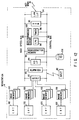
workstation 14. Theworkstation 14 comprises aninput device 80, anoutput device 82, analarm generator 83, a hard disk interface (HD I/F) 84, asemiconductor memory 86, aCPU 88, atimer 90, aROM 92, a network interface (LAN I/F) 94, a plurality ofimage memories 100, a plurality of CRT displays 102, a hard disk unit (HD) 106, and adata expansion circuit 108. Of these components, theinput device 80, theoutput device 82, thealarm generator 83, the HD I/F 84, thesemiconductor memory 86, theCPU 88, thetimer 90, theROM 92, the LAN I/F 94, and thedata expansion circuit 108 are connected to acontrol bus line 96. Theoutput device 82, thealarm generator 83, the HD I/F 84, thesemiconductor memory 86, theROM 92, and the LAN I/F 94 are connected to a highspeed bus line 98. The LAN I/F 94 is connected to thenetwork 16. - The
image memories 100 are provided in one-to-one correspondence with one or more (in this case, four) CRT displays 102. Each of theimage memories 100 has two or three overlay screens (plane memories) and is connected to theoutput device 82. An output from theimage memory 100 is displayed on thecorresponding CRT display 102. TheHD unit 106 is connected to the HD I/F 84. In theworkstation 14, the image data input via the LAN I/F 94 in the form of the compressed image data, the corresponding relevant data, and the examination data in units of examinations are stored in theHD unit 106. - In order to perform an image reading, a doctor selects an image and the attribute data and the image is displayed on the
CRT display 102 via theoutput device 82. The image to be displayed is selected among the images for one examination using the image ID input by the doctor. If the compressed image data is read out from theHD unit 106, the compressed data is expanded by thedata expansion circuit 108 and then stored in thesemiconductor memory 86. The relevant data and the examination data are also stored in thesemiconductor memory 86. The image data is read out from thesemiconductor memory 86 and is displayed on theCRT display 102 to be read or viewed by the doctor. For example, when an object to be image-read is a conventional X-ray radiograph, front and side images are usually displayed. When the patient has been examined, both non-read and past images (other than the non-read image; reference image) are usually displayed to perform comparative image reading. - The manner in which the images are displayed on the CRTs is registered in a CRT image display control table as shown in Fig. 14. The table is formed by associating the examination ID and the image ID with the serial number of the CRTs. The table is stored in the
semiconductor memory 86. - The image data which are sequentially transferred to the
workstation 14 from thedata base 12 are sequentially processed with a predetermined CAD algorithm. - A timing at which the CAD operation is started will be described below. After image data, examination data, and relevant data of one patient are transferred to the
HD unit 106 of theworkstation 14, the examination data and relevant data are read out sequentially from theHD unit 106 to thesemiconductor memory 86 by theCPU 88. - Since the CAD operation is performed in which one of a plurality of different CAD algorithms suitable for the image data is selected, the
ROM 92 includes a table indicating the name of a CAD algorithm and the items of the attribute data of the image data capable of being applied with the CAD algorithm, as shown in Fig. 15. The items of the attribute data of the image data to be analyzed and corresponding items of the attribute data of each CAD algorithm included in the table shown in Fig. 15 are compared with each other to determine whether or not the CAD algorithm can be applied to the image data. For example, a CAD algorithm for an interstitial lung disease is performed only when the modality is a conventional radiograph, the examination object is a chest, the imaging direction is a front, and the result of CAD is nothing. If the CAD algorithm is not applied to the image data, nothing is stored in the item of the result of CAD. If other than nothing is stored in the item of the result of CAD, it means that the CAD algorithm is used for the image data. Therefore, since the examination data (Fig. 2) and the relevant data (Fig. 6) are already read out into thesemiconductor memory 86, the items of modality and examination object are extracted from the examination data, and the items of imaging direction and result of CAD are extracted from the relevant data. These items are compared with items for each algorithm stored in the table shown in Fig. 15. The table of Fig. 15 is read out from theROM 92 and is stored in thesemiconductor memory 86. If they are equal to each other, the image is determined to be an object to which the CAD algorithm is to be applied. Therefore, an arithmetic operation of the CAD algorithm corresponding to the image data is started. - First, the image data determined to be an object to which the CAD algorithm is to be applied is read out into the
semiconductor memory 86. TheCPU 88 executes the CAD algorithm stored in theROM 92 and stores the result of CAD in thesemiconductor memory 86. TheCPU 88 issues a serial number for the CAD ID and writes the CAD ID for retrieving the result of CAD in the item of the result of CAD in the relevant data (Fig. 6) stored in thesemiconductor memory 86. TheCPU 88 also writes the address storing the result of CAD in the relevant data. The default data of the address of the result of CAD is text data denoting nothing. When the operation for one CAD algorithm is ended, it is determined whether the next CAD algorithm can be applied to the image data. - The examples of the CAD algorithm written in the
ROM 92 are as follows. A CAD algorithm for detecting a micro calcification in mammography is disclosed in Unexamined Japanese Patent Application No. 2-152443. A CAD algorithm for measuring the size of the heart and lung is disclosed in United States Patent Application No. 275,720 (filed November 23, 1988). A CAD algorithm for detecting an interstitial lung disease is formed of the following algorithms: - #1: An algorithm (which is schematically shown in Fig. 17, and illustrated in detail in Fig. 18) for setting ROIs (symbolized by □ in Fig. 16) for the CAD algorithm for one frame of the image data.
- #2: An algorithm (which is schematically shown in Fig. 19) for calculating a physical amount of texture (which is an index indicating the magnitude and the length of period of a density variation in a texture pattern) in the ROI.
- #3: An algorithm (the flow chart of which is shown in Fig. 20, and the arrangement in Fig. 21) for applying a threshold to the calculated physical amount of texture to determine abnormality or normality of the ROI.
- Of these algorithms, the
algorithms # 1 and #2 are described in USP 4,851,984, and therefore a detailed description thereof will be omitted. In addition, since thealgorithms # 3 is described in USP 4,839,807, a detailed description thereof will be omitted. - The results of the CAD algorithm and the classification of the normality are temporarily stored in the
semiconductor memory 86. The detailed description for the case of the interstitial lung disease will be described. It is to be noted that "diffuse" is determined for those classified to be abnormal (i.e., those determined to be clustered abnormal ROIs in the flowchart shown in Fig. 20) because of the presence of clusters (grouped abnormal ROIs), and "local" is determined for abnormalities other than these; they are called patterns of abnormality. The pattern of abnormality is included as one item in the result of CAD of Fig. 22, and the type of pattern is written in this item as text characters, e.g., denoting local. Fig. 23 shows a practical example of the result of CAD in the case of an abnormal ROI. Here, a TPF represents a true positive fraction and an FPF represents a false positive fraction. failure. The ID of the result of CAD and the address of this CAD result data in thesemiconductor memory 86 are additionally written as items in the relevant data (Fig. 5). When the result of CAD is stored in thedata base 12, the ID and address are registered in the examination directory as shown in Fig. 9. The above operation is performed plural times if plural CAD algorithms can be applied to the image data. If plural results of CAD and addresses are obtained, all the plural IDs and addresses are stored in the examination directory. - The CAD result is output in response to application of an output request trigger. Therefore, while image reading is performed (a conventional X-ray radiograph of a chest is read or viewed in case of interstitial lung disease detection CAD), various commands including this output request must be input from the
input device 80 of theworkstation 14. In this embodiment, the description of theinput device 80 will be given by using a touch panel type device. It is also possible to use a general device, such as a keyboard as theinput device 80. - Fig. 24 shows an example of the
input device 80. This touch panel comprises acommand display 110 on which the names of commands is displayed, apanel 112 on which thecommand display 110 is arranged, and atransparent sensor board 114 located on thecommand display 110. When a position corresponding to the name of a command is selectively touched with a finger, thesensor board 114 senses the touched portion. - When, for example, several command buttons are displayed on the output device, an operator can recognize a command display through the
sensor board 114. The operator selects a command by touching thesensor board 114, thus executing the command. A button (CAD button shown in Fig. 25) for requesting an output of a result of CAD is prepared (displayed) on the touch panel. Detecting depression on this CAD button on the touch panel is a trigger for requesting the CAD result output. - Since the CAD result can be output in various modes, the mode of outputting the CAD result is determined next. The
CPU 88 reads out the relevant data (Fig. 6) corresponding to the examination ID and image ID included in the CRT image display control table (Fig. 14). Further, theCPU 88 reads out the CAD result ID and CAD result address from this relevant data, thereby reading out or retrieves the result of CAD (Fig. 22). - An example of CAD result output is described below. The
CPU 88 starts the program in theROM 92 and outputs a CAD result (Fig. 23) relating to the abnormality to a corresponding output device according to the pattern of the abnormality. In this program, the item of data denoting the pattern of abnormality is extracted from the result of CAD (Fig. 23) relating to the abnormality and stored in thesemiconductor memory 86. If the pattern of abnormality is a diffused pattern, a text sentence generator is activated in order to output an abnormality alarm in the form of a text sentence. If the pattern of abnormality indicates local, the alarm (marker)generator 83 is activated in order to indicate the location of abnormality by means of a marker. - In this case, the text sentence represents the location of abnormality on an image by means of words, thereby making an alarm. For this purpose, as shown in Fig. 26, a screen of the display is equally divided into six regions in advance, and a name is assigned to each region. A table (Fig. 27) showing a correspondence between the names and the x, y coordinates of the regions is stored in the
ROM 92. The right and left is defined as viewed from the patient. TheCPU 88 starts the program in theROM 92. In this program, the x, y coordinates of the location of the abnormal ROI is extracted from the CAD result and an expression of abnormality is read out from the table shown in Fig. 28 and stored in theROM 92 in accordance with the location of the abnormality. The readout expression data is stored in thesemiconductor memory 86 to be inserted into the text sentence. If plural CAD results are obtained, the above operation is repeated for the number of the CAD results. The text sentence is, for example, "interstitial lung disease, upper right lung abnormal." In this case, the expression of the underlined portion changes in accordance with an abnormal portion. Subsequently, character string data of the text sentence is converted into dot patterns in units of characters. Thereafter, with reference to the CRT image display control table (Fig. 14), one text line (white) is provided in the uppermost stage of an image memory 100 (overlay screen) corresponding to the CRT displaying the image, and dot patterns of black characters are stored in the text line of theimage memory 100, as shown in Fig. 29. - The marker is a means for representing the location of abnormality on an image by using an arrow. The
CPU 88 of theworkstation 14 starts the program in theROM 92 and reads out the location of abnormality from the CAD result data (Fig. 22), thus forming the shape of a marker as shown in Fig. 29, based on a font pattern of theROM 92. In this case, although d (diagonal of the square) = 1.5 cm is preferable, d is not limited to this value but can be changed freely. The screen is divided into right and left portions as viewed from the operator. If the location (the center of ROI indicated by a symbol ×) of abnormality is present on the right side of the screen, the arrow shown in Fig. 30 is converted directly into a bit pattern. If, by contrast, the location is present on the left side, the arrow of Fig. 30 is inverted symmetrically about a longitudinal line (alternate long and short dashed line in Fig. 30) including the center of ROI, i.e., in a mirrorlike manner and the resulting mirror image of the arrow as indicated by a broken line in Fig. 30 is converted into a bit pattern. - In addition, the bit pattern data is written in a location corresponding to the position of abnormality in the image memory 100 (overlay memory) corresponding to the CRT displaying the image. If a plural CAD results are obtained, the above operation is repeated until all the CAD results are read out and written into the overlay memory. The data in the image memory 100 (overlay memory) is displayed on the CRT overlapped with the image data. The display color of the bit pattern data of the marker is switched between black and white in synchronism with the
timer 90. Thus, the effect of alarming of the marker is enhanced. It is noted that the period of switching is 2Hz. - At this time, though all the CAD results are simultaneously displayed on the CRT, some of them may be selectively displayed. The names of buttons displayed on the touch panel are changed in accordance with the needs of the operator. For example, the names of the buttons are changed in accordance with the CAD algorithm now applying to the image data. A label "ID", "MC", and "BH" are provided for buttons in case of an interstitial lung disease detection CAD, micro calcification detection CAD, and heart size measuring CAD. When a CAD algorithm is selected, the CAD result corresponding to the algorithm is written in the overlay memory and the other results are deleted from the overlay memory.
- Another mode of CAD result output will be described in which the CAD result has a hierarchical structure. That is, a summary of the CAD result is output first by means of, e.g., the text sentence and the marker as described above, and then details are output. For this purpose, a button for requesting a CAD detail output is prepared on the input device (touch panel) 80 (Fig, 25) of the
workstation 14. In other words, the names of buttons on the touch panel are changed in accordance with the application used by an operator. When depression on the CAD detail output button on the touch panel is sensed while the text sentence and the marker are displayed, a trigger for requesting an output of the CAD detailed result is generated. - The output of the CAD detailed result will be described below. It is assumed that the text sentence is already formed and stored in the form of black characters on a white background as shown in Fig. 29 in the image memory 100 (overlay screen). The
CPU 88 starts the program in theROM 92 to read out the CAD result data (Fig. 22) from thesemiconductor memory 86. TheCPU 88 forms an arrow marker for data having abnormality independently of the pattern of the abnormality. The marker indicates the location of the abnormality on an image by means of an arrow. - The
CPU 88 reads out the location of the abnormality and forms the shape of the marker as shown in Fig. 31, based on the font pattern in theROM 92. At this time, the screen is divided into right and left portions. If the abnormality location is present on the right side viewed from the operator, the arrow of Fig. 31 is converted directly into a bit pattern. If, on the other hand, the abnormality location is present on the left side, the arrow of Fig. 31 is mirrorlike-inverted symmetrically about a longitudinal line (alternate long and short dashed line in Fig. 31) including the location of the abnormality, and the resultant mirrorlike arrow as indicated by a broken line in Fig. 31 is converted into a bit pattern. In addition, the type (e.g., nodular) and the degree (e.g., 75%) of the abnormality are read out from the CAD result data and are converted into a bit pattern, as shown in Fig. 31. Unlike the bit pattern of the arrow, the bit pattern of characters of the type and degree is not mirrorlike-inverted regardless of whether the abnormality location is present on the right side or the left side. - This bit pattern data is written in a location corresponding to the position of the abnormality in the image memory 100 (overlay screen) corresponding to the
CRT 102 displaying the image. As a result, the arrow marker associated with the characters indicating the type and the degree of the abnormality (Fig. 31) is displayed, together with the text sentence shown in Fig. 29, on the screen. - The data in the image memory 100 (overlay screen) is displayed overlapped on the examination image. At this time, the color of the data display on the overlay screen is switched between black and white in synchronism with the
timer 90. The period of switching is 2Hz. - An example of an option output of the CAD detailed result will be described below. As in the case of the trigger for the detailed output, a button for requesting a detailed option output of the CAD result is displayed on the input device (touch panel) 80 of the
workstation 14 as a trigger for the option output. When depression on the CAD detailed option output button on the touch panel is sensed while the detailed output is performed, the trigger for requesting the CAD detailed option output is attained. - It is supposed that the text sentence is already formed and stored in the form of black characters on a white background as shown in Fig. 29 in the image memory 100 (overlay screen). The
CPU 88 starts the program in theROM 92 to read out the CAD result data (Fig. 22) from thesemiconductor memory 86 and forms an arrow marker for data having abnormality independently of the pattern of the abnormality. This marker represents the location of the abnormality on the image by means of an arrow. - The
CPU 88 reads out the location of the abnormality and forms an arrow marker and a square ROI marker, as shown in Fig. 32, based on the font pattern of theROM 92. Here, the screen is divided into right and left portions. If the abnormality location is present on the right side, the arrow and the ROI of Fig. 32 are converted directly into bit patterns. If the location is present on the left side, the arrow of Fig. 32 is inverted in a mirrorlike manner, and the resulting arrow indicated by a broken line in Fig. 32 and the ROI are converted into bit patterns. This bit pattern data is written in the location corresponding to the position of the abnormality in the image memory 100 (overlay screen) corresponding to the CRT displaying the image in the CRT display image control table (Fig. 12). - The data in the image memory 100 (overlay screen) is displayed overlapped on the examination image. At this time, the color of the data display on the overlay screen is switched between black and white in synchronism with the
timer 90. The period of switching is 2Hz. - Another example of the option output will be described. When another option output is requested, the
CPU 88 starts a given program in theROM 92 to read out ROC (Receiver Operator Curve) data included in the CAD result from thesemiconductor memory 86, thus forming an ROC curve. As shown in Fig. 33, the ROC curve is one of examples for indicting the ability of CAD and is so formed as to be fitted in a portion below and to the right of the image. In the ROC curve, the abscissa denotes the FPF and the ordinate denotes the TPF. The ROC curve is converted into a bit pattern. The bit pattern data is written in the image memory 100 (overlay screen) corresponding to the CRT displaying the image. The data in the image memory (overlay memory) 100 is displayed on the CRT overlapped with the examination image. - An example of a request trigger for ending the output of the CAD result will be described below. When the image reading of a conventional X-ray radiograph of a chest is performed and the image and the CAD result are displayed on a CRT screen, the trigger for ending the CAD result output is automatically generated upon stopping the image display in order to display another image. When the output is ended, the image display is continued, and only the display on the overlay screen is turned off. Further, the touch panel may include a button for providing the command representing the end of the image reading and the relevant data is updated as being read if the button is depressed.
- A command for requesting the end of the CAD output can also be applied from the
input device 80 of touch panel type. - It is to be noted that the CAD data is preferably stored even when its output (display) is stopped. The CAD result is added to the updated relevant data, as shown in Fig. 34, and supplied to the
data base 12 to be stored therein. In thedata base 12, all the CAD IDs and CAD result addresses in the relevant data are stored in the examination directory (Fig. 9). In a subsequent image reading, if an image transfer request is supplied to thedata base 12, the image data and the corresponding examination and relevant data are transferred by thenetwork 16 and stored in thesemiconductor memory 86 of theworkstation 14. At the same time, the CAD result ID is read out and all the CAD results are retrieved based on the CAD IDs. In this case, as shown in Fig. 35, the address of the CAD result written in the relevant data is converted into the address on thesemiconductor memory 86 and is stored in the relevant data. - According to this embodiment as has been described above, the following effects can be obtained. That is, in addition to a medical image, CAD data concerning the image is also displayed. Therefore, an erroneous diagnosis due to an oversight of a disease can be prevented in medical image diagnosis, thus increasing diagnosis precision. Labors can be reduced in a diagnosis operation performed by a doctor (operator). In medical image diagnosis, particularly in an image reading operation, an erroneous diagnosis caused by an oversight of a disease can be prevented to improve diagnosis precision. Since the CAD data is obtained by analyzing medical images using a computer, objective and quantitative results can be obtained. Therefore, it is possible to prevent an erroneous diagnosis which is a result of subjective determination by a human being, and consequently diagnosis precision can be increased. In medical image diagnosis, a doctor who is not an expert of an image of interest sometimes cannot make a satisfactory diagnosis. According to the present invention, diagnosis precision can be improved also in this case.
- As the CAD data, the position, the type, or the degree of abnormality is displayed, so that the abnormality can be readily recognized. As a result, an erroneous diagnosis caused by an oversight of a disease can be prevented to improve diagnosis precision.
- Arithmetic operation calculating the CAD data is started by a computer before an output request for the CAD data is generated. Therefore, it is possible to shorten a time from generating the output request to displaying the CAD data.
- When several algorithms for obtaining CAD data are available, an inappropriate processing is performed for an image data of interest unless the image data is correctly assigned to the algorithm, and erroneous CAD data results. According to this embodiment, however, since a suitable algorithm is selected for each image, output of erroneous CAD data can be prevented to increase diagnosis precision.
- Since the CAD result is stored in the
data base 12, an image which is diagnosed once need not be analyzed again. - A CAD algorithm is determined for each diagnosis of interest, and the algorithms are selectively executed in accordance with each object. Therefore, it is possible to prevent a production of CAD data which may cause an erroneous diagnosis in the case when an unsuitable algorithm is applied to an object. Further, the attribute data includes the modality, the examining object, and the imaging direction, and an algorithm is executed when these items of the attribute data coincide with those of an object image of the algorithm. Therefore, an unsuitable algorithm is not applied to the image.
- An alarming means which strongly attracts attention of the doctor is used as a means for alarming abnormality. Therefore, an erroneous diagnosis due to an oversight can be prevented to increase diagnosis precision. An optimal alarming means is selected to attract attention in accordance with the type of abnormality. Therefore, it is possible to prevent an erroneous diagnosis caused by an oversight, thus improving diagnosis precision. By flickering the alarm display, the alarming means strongly attracts attention to prevent an erroneous diagnosis resulting from an oversight, thus improving diagnosis precision.
- The CAD data is hierarchically constructed and output gradually from its summary to details. Therefore, a large number of different types of CAD data are not simultaneously displayed to cause a cumbersome operation. Thus, an erroneous diagnosis can be prevented to increase diagnosis precision. For example, the position of abnormality alone is output first as the CAD data. If the abnormality cannot be clearly determined, a doctor freely makes output requests for, e.g., the degree, the type, and the pattern of the abnormality, thus avoiding a cumbersome operation to increase diagnosis precision. In this case, a usable command (button) is prepared for each level (hierarchical level) of contents at which the CAD data is output. Since a user need only select a command of interest from the prepared commands, a labor for selecting from a large number of commands is reduced.
- Before application of the CAD algorithm to a given image data, it is determined whether the CAD algorithm can be applied to the image data based on the attribute data of the image data and only the algorithm which is determined to be able to apply to the image data is applied to the image data. Therefore, it is possible to prevent lowering the quality and precision of diagnosis due to the output of the erroneous CAD data.
- The CAD system according to the present invention is described as being incorporated into the PACS. However, it is possible to realize a stand-alone type CAD system according to the present invention.
- Plural CAD algorithms are stored in the system and an optimum one is automatically selected based on the relevant data of the object image data. Therefore, it is possible to reduce the labors of the doctor for selecting the suitable algorithm, inputting the respective image data, and outputting the respective CAD data.
- The computer starts an arithmetic operation for calculating the CAD data before an output request for the CAD data is generated. Therefore, it is possible to shorten a time from generating the output request to displaying the CAD data.
- The numerical data denoting the CAD result includes many items. If all the data are output, the output becomes complicate. According to the first embodiment, the CAD data are stored in the form of a table and only desired data is output by retrieving the data from the table using the retrieval key corresponding to the desired condition. Therefore, the CAD result can be output in a simple form.
- The attribute data includes an item of data denoting whether or not the image data has been read or viewed. Based on this attribute data, the CAD result of the image data which has been read or viewed is not output. Therefore, it is possible to prevent a confusion in which the CAD result different from the reading report is output. Based on this attribute data, only the image data which has not been read or viewed is analyzed using the CAD algorithm. Therefore, a time from generating the output request to displaying the CAD data becomes shorter than that in the case of all the image data are analyzed. Further, the attribute data includes an item of data representing the CAD result and the image data which has been analyzed is not analyzed again. Therefore, it is possible to further shorten a time from generating the output request to displaying the CAD data.
- Other embodiments of the present invention will be described below.
- A second embodiment comprises, in addition to the
workstation 14 for displaying the image as shown in Fig. 12, aworkstation 14a having aCAD processor 120 as shown in Fig. 36. Thisworkstation 14a for obtaining CAD data is different from theworkstation 14 in that acontroller 90a is provided in place of thetimer 90. In terms of an operation, the second embodiment is different from the first embodiment in a timing at which a CAD arithmetic operation is started. - In the second embodiment, when image data, examination data, and relevant data of one patient are transferred to the
HD unit 106 of theworkstation 14a, the examination data and the relevant data are read out sequentially from theHD unit 106 into thesemiconductor memory 86 by theCPU 88. TheROM 92 stores the table denoting the relationship between the name of the CAD algorithm and the attribute data of the image data which can be adapted to the CAD algorithm as shown in Fig. 15. Therefore, since the examination data (Fig. 2) and the relevant data (Fig. 6) are already read out into thesemiconductor memory 86, the modality and the examining object are read out from the examination data, and the imaging direction is read out from the relevant data. These read out items of data are stored in thesemiconductor memory 86. These items of data are compared with the attribute data of the image stored in the table (Fig. 15) of theROM 92. - If these items are coincide with those of a given CAD algorithm, e.g., interstitial lung disease detection CAD, this image is determined to be an image to which the interstitial lung disease detection CAD algorithm can be applied, and the operation of the CAD is started. At this time, the
CPU 88 in theworkstation 14a designates activation of the CAD processor 120 (Fig. 36), and supplies input data to theprocessor 120. The input data given to theCAD processor 120 includes the image data, the examination data, and the relevant data. TheCAD processor 120 has its own CPU, and by means of the CPU it executes the CAD operation and outputs a CAD result. The CAD result is temporarily stored in the memory as data having the format shown in Fig. 22. In addition, the ID and the address of the CAD result data are additionally written in the relevant data (Fig. 6). - As described above, according to the second embodiment, since the display and the CAD arithmetic operation are separately performed at
different workstations modality 10, theworkstation 14, and thedata base 12, a long processing time is required for they share a single CPU. However, since theCAD processor 120 has aCPU 88 for a processing purpose only, the processing time is shortened. - A third embodiment is different from the first embodiment in that a CAD result is output as a sound. For this purpose, a workstation of this embodiment has a sound generator as shown in Fig. 37 in addition to the arrangement shown in Fig. 10. The
CPU 88 of theworkstation 14 reads out relevant data using the CRT image display control table (Fig. 14). TheCPU 88 also reads out CAD results (Fig. 22) by reading out the CAD result address from the relevant data. When the CAD result is to be output, theCPU 88 starts a program in theROM 92 and assigns the CAD result having abnormality to a corresponding output device in accordance with the pattern of the abnormality. In this program, the CAD results and the classification of the CAD result are read out from thesemiconductor memory 86, and, if the type of abnormality indicates "diffuse", a text sentence generator is activated in order to output an abnormality alarm in the form of a text sentence. If the type of abnormality indicates "local", a marker generator and the sound generator shown in Fig. 37 are activated in order to indicate the position of the abnormality by means of a marker and a sound. - When the CAD operation result is read out from the
semiconductor memory 86, if the pattern of abnormality indicates "local", a sound of "abnormality present" is simply generated. If, however, the pattern of abnormality indicates "diffuse", a statement formed as a text sentence is automatically read. The text sentence is, for example, "interstitial lung disease, upper right lung abnormal." The expression in the underlined portion changes in accordance with an abnormal portion. Next, theCPU 88 activates a program in theROM 122 and converts character string data in the text sentence into a voice sound. "Interstitial lung disease, upper right lung abnormal" is stated by generating three groups of words, interstitial lung disease, upper right lung, and abnormal. Since the expression in the underlined portion changes in accordance with an abnormal portion as described above, asound data base 124 is also provided to generate words for this purpose. - According to the third embodiment as described above, in specifying the position of abnormality by means of a sentence or a sound, words representing a position are used to make it easy to recognize the abnormality. Therefore, an oversight of a disease and consequently an erroneous diagnosis can be prevented to lead to an increase in diagnosis precision.
- As a fourth embodiment, an embodiment of automatically outputting a CAD result will be explained. The arrangement of a workstation of the fourth embodiment is identical to that of the first embodiment shown in Fig. 12. In the fourth embodiment, however, even if no CAD result request is present during image reading of a conventional X-ray radiograph of chest, the result is automatically displayed.
- For this purpose, each time an image is displayed, the
CPU 88 refers to the CRT image display control table (Fig. 14) and checks whether the ID of the CAD result is included in the relevant data of the displayed image, i.e., whether nothing is stored in the CAD result ID, and in this manner checks whether the displayed image is an object of the CAD. If theCPU 88 determines that the displayed image is an object of the CAD, it measures a predetermined time from the start of image display by means of thetimer 90, and automatically generates a trigger for requesting a CAD result output when the predetermined time has elapsed. This predetermined time can be arbitrarily changed. - In this manner, the output request for the CAD data can be omitted, and this results in a reduction in labors. In addition, if the CAD data is output immediately after an image is displayed, an operator or doctor may have a preconceived knowledge. Therefore, CAD data is output when a certain time has elapsed after an image is displayed. As a consequence, an erroneous diagnosis due to an oversight is prevented to improve diagnosis precision.
- A fifth embodiment as another example of automatically outputting the CAD result will be described. Here, the arrangement of a workstation of this embodiment is also the same as that shown in Fig. 12. First, each time an image is displayed, the
CPU 88 refers to the CRT image display control table (Fig. 14) and checks whether the ID of the CAD result is included in the relevant data of the displayed image, i.e., whether nothing is stored in the CAD result ID, and in this manner checks whether the displayed image is an object of the CAD. If theCPU 88 determines that the displayed image is an object of the CAD, it measures a number of times (the number of applications of the CAD algorithm) at which the image is displayed from the start of the image reading for the patient and writes the number of times into the relevant data (Fig. 6). The number of times is initially set to zero and increased by one every time the image is displayed. TheCPU 88 automatically generates a trigger for requesting a CAD result output when the number of times reaches a predetermined time which can be arbitrarily set. - In this manner, since an output request for CAD data can be omitted, labors can be reduced. In addition, if CAD data is output immediately after an image is displayed, an operator or doctor may have a preoccupied knowledge. Therefore, CAD data is not output when an image is displayed for the first time and image reading is performed but output when the image is displayed for a predetermined time or the image display is switched. The result is that an erroneous diagnosis caused by an oversight is prevented to improve diagnosis precision.
- The fourth and fifth embodiments are embodiments automatically outputting a CAD result. Next, a sixth embodiment of automatically ending outputting of a CAD result will be described. The arrangement of a workstation of this embodiment is identical to that shown in Fig. 12. When, for example, image reading of a conventional radiograph of a chest is performed, a display of the CAD result is automatically stopped even if no CAD result request is present. For this purpose, each time an image is displayed, the
CPU 88 refers to the CRT image display control table (Fig. 14) and checks whether the ID of the CAD result is included in the relevant data of the displayed image, i.e., whether nothing is stored in the CAD result ID, and in this manner checks whether the displayed image is an object of the CAD. If theCPU 88 determines that the displayed image is an object of the CAD, it measures a predetermined time from the start of image display by means of thetimer 90, and automatically generates a trigger for requesting the end of the CAD result output when the predetermined time has elapsed. This predetermined time can be arbitrarily changed. Upon the end of outputting, theCPU 88 turns off all overlay screens displayed on CRTs. - According to this embodiment, since an output end request for CAD data can be omitted, labors are reduced. In addition, CAD data remaining on an image for a long time makes it difficult for an operator or doctor to observe details of an image. As in this embodiment, however, by automatically ending display of CAD data after the data has been displayed for a predetermined time, an erroneous diagnosis is prevented to increase diagnosis precision.
- Various commands must be input in the present invention, so a seventh embodiment relating to a modification of the input device will be described below. During image reading of a conventional radiograph of a chest, when an icon displayed on a CRT screen is designated (clicked) by a pointing device such as a mouse, a menu window as shown in Fig. 38A appears at a corner, in this case, the upper right corner of the screen. It is to be noted that this menu window shows only buttons which can be used by an operator at the time of click. If it is electrically sensed that a CAD button in the menu window on the screen is designated by the pointing device, a trigger for requesting a CAD result output is generated.
- Similarly, when the icon displayed on the CRT screen is designated (clicked) by the pointing device such as a mouse, as shown in Fig. 38B, while the CAD output is performed, the menu window emerges. If a button for requesting a CAD detail result output in the menu window is designated, a trigger for requesting the CAD detail result output is generated. When the icon displayed on the CRT screen is designated (clicked) by the pointing device such as a mouse while the CAD output is performed, the menu window appears. If a button for requesting an option output in the menu window is designated, a trigger for requesting an option output is generated. When the icon displayed on the CRT screen is designated (clicked) by the pointing device such as a mouse while the CAD output is performed, the menu window emerges. If a button for requesting a CAD diagnosis level output in the menu window is designated, a trigger for requesting the CAD diagnosis level output is generated. When the icon displayed on the CRT screen is designated (clicked) by the pointing device such as a mouse while the CAD output is performed, the menu window appears. If a button for requesting a CAD result output end in the menu window is designated, a trigger for requesting the CAD detail output end is generated. Upon the end of outputting, overlay screens are turned off.
- According to this embodiment as described above, a menu window including buttons having command names is displayed on the CRT screen. By designating a command with by means of a pointing device such as a mouse, a command for outputting CAD data can be input. In addition, since the menu window is not constantly displayed but can be selectively displayed, an operator (doctor) can display commands only when he or she needs them. Therefore, an annoyance caused by frequent changes in commands displayed can be reduced. In this case, a usable menu is prepared for each level (hierarchical level) of the contents of CAD data to be output. Therefore, since a user need only select a menu of interest from the prepared menus, a labor of selecting from a large number of menus is reduced.
- An eighth embodiment concerned with coloring of a marker and a text sentence will be described below. The arrangement of a workstation is the same as that shown in Fig. 12. With reference to the CRT image display control table (Fig. 14), an overlay screen corresponding to a CRT not having "nothing" in the ID of the CAD result of relevant data of a displayed image is overlaid on the examination image displayed on the CRT. At this time, the data displayed on the overlay screen is flickered in an arbitrary color, such as red, while being synchronized by the
timer 90. The period of flickering is 2 Hz. - According to the eighth embodiment, it is possible to strongly attract attention because of the color of the alarm display. As a result, an erroneous diagnosis caused by an oversight can be prevented to consequently increase diagnosis precision. This effect can be further enhanced by flickering the alarm display.
- A ninth embodiment in which a CAD arithmetic operation is started by the modality, such as a film digitizer 18 (Fig. 4) will be described. The arrangement of a workstation is identical to that shown in Fig. 12. In this embodiment, when the
film digitizer 18 digitizes all the image data for one patient and inputs the imaging direction, theCPU 88 reads out examination data and relevant data sequentially from theHD unit 106 into thesemiconductor memory 86. In order to refer to the table (Fig. 15) of CAD algorithms and corresponding attribute data, the modality and the examination object are read out from the examination data (Fig. 2) and the imaging direction and the CAD result ID address are read out from the relevant data (Fig. 6). These readout items of data are stored in thesemiconductor memory 86. These items of data are compared with the attribute data of the image stored in the table (Fig. 15) of theROM 92. If these items are coincide with those of a given CAD algorithm, this image is determined to be an image to which the given CAD algorithm can be applied, and the operation of the CAD is started. - Upon the start of the CAD operation, image data determined to be an object of the CAD is read out into the
semiconductor memory 86. TheCPU 88 executes a CAD operation program written in theROM 92 and stores the result in thesemiconductor memory 86. TheCPU 88 transfers, as data flowing through thenetwork 16, the image data, the relevant data, the CAD result, and the examination data (for each examination) to thedata base 12 via the LAN I/F 94. As shown in Fig. 34, thedata base 12 handles the CAD result data as a part of the relevant data. - When data is transferred to the
workstation 14 during image reading, the transferred data is temporarily stored in theHD unit 106. However, the CAD result is read out from theHD unit 106 into thesemiconductor memory 86 upon reception of a CAD output request as a trigger. In this case, theworkstation 14 does not perform any operation associated with the CAD but simply displays the CAD result. Whenever an image is displayed on the image display device (workstation), the CAD result for the displayed image is stored in thesemiconductor memory 86. Therefore, a time from generation of an output request to display the CAD result is shortened. - In a tenth embodiment, a timing at which an arithmetic operation of a CAD is started is when all the image data of one patient is transferred to the
data base 12. At this time, theCPU 88 reads out examination data and relevant data sequentially from theHD unit 106 into thesemiconductor memory 86. In order to refer to the table (Fig. 15) of CAD algorithms and corresponding attribute data, the modality and the examination object are read out from the examination data (Fig. 2) and the imaging direction and the CAD result ID address are read out from the relevant data (Fig. 6). These readout items of data are stored in thesemiconductor memory 86. These items of data are compared with the attribute data of the image stored in the table (Fig. 15) of theROM 92. If these items are coincide with those of a given CAD algorithm, this image is determined to be an image to which the given CAD algorithm can be applied, and the operation of the CAD is started. - Upon the start of the CAD operation, image data determined to be an object of the CAD is read out into the
semiconductor memory 86. TheCPU 88 executes a CAD operation program written in theROM 92 and stores the result in thesemiconductor memory 86. TheCPU 88 transfers, as data flowing through thenetwork 16, the image data, the relevant data, the CAD result, and the examination data (for each examination) to thedata base 12 via the LAN I/F 94. As shown in Fig. 34, thedata base 12 handles the CAD result data as a part of the relevant data. - When data is transferred to the
workstation 14 during image reading, the transferred data is temporarily stored in theHD unit 106. However, the CAD result is read out from theHD unit 106 into thesemiconductor memory 86 upon reception of a CAD output request as a trigger. In this case, theworkstation 14 does not perform any operation associated with the CAD but simply displays the CAD result. Whenever an image is displayed on the image display device (workstation), the CAD result for the displayed image is stored in thesemiconductor memory 86. Therefore, a time from generation of an output request to display the CAD result is shortened. - Fig. 39 is a block diagram showing the arrangement of an eleventh embodiment. In the eleventh embodiment, a
CAD processor 14a as shown in Fig. 36 is connected to the arrangement of the PACS shown in Fig. 1. When a request of starting a CAD operation is generated in theworkstation 14, theCAD processor 14a is used to perform only the CAD operation at a high speed. Therefore, theworkstation 14 transfers data required for the CAD operation to theCAD processor 14a, and only the result is returned to theworkstation 14. - A timing at which the CAD operation is started is similar to that in the tenth embodiment. However, unlike in the tenth embodiment, the CAD operation is performed by the
CAD processor 14a. Theworkstation 14 supplies the image data, the examination data, and the relevant data to theCAD processor 14a via thenetwork 16. As shown in Fig. 36, theCAD processor 14a has its own CPU, and by means of the CPU it executes the CAD operation and outputs the CAD result. The result of the CAD operation is transferred as result data having the format shown in Fig. 22 to theworkstation 14 via thenetwork 16. As shown in Fig. 34, theworkstation 14 or thedata base 12 handles the CAD result as a part of the relevant data. - When data is transferred to the
workstation 14 during image reading, the transferred data is temporarily stored in theHD unit 106. The CAD result, however, is read out from theHD unit 106 into thesemiconductor memory 86 upon reception of an output request for the CAD as a trigger. In this case, theworkstation 14 does not perform any operation associated with the CAD but simply displays the result. - Processing executed by devices such as the modality, the workstation, and the data base takes a long processing time for they share a CPU. In this embodiment, however, since the processor having a CPU for a processing purpose only executes the processing, a processing time can be shortened.
- As a twelfth embodiment, an embodiment concerned with a modification of a marker will be described below. Figs. 40A to 40E show modifications of a marker for pointing the ROI, and Figs. 41A to 41F show modifications of a marker for surrounding the ROI. Pointing the ROI includes a case in which the direction of an arrow points the center of the ROI as shown in Fig. 42A and a case in which it points a position other than the center as shown in Fig. 42B.
- According to this embodiment, an alarming means which strongly attracts attention is used in order to alarm abnormality. Therefore, an oversight and therefore an erroneous diagnosis can be prevented, and this results in an improvement in diagnosis precision.
- A thirteenth embodiment in which an on/off of the CAD result display is controlled for each of the CRTs will be described. The touch panel includes plural CAD result display buttons provided for the respective CRTs. In order to display only the CAD result on the
CRT # 1, it is necessary to depress the CAD result display buttons for theCRT # 1. When the depression of that button is detected, the ID of the image displayed on theCRT # 1 is read out from the CRT display control table (Fig. 14). The CAD result address is read out from the relevant data of the image and the CAD result data is written into the overlay memory for theCRT # 1, thereby displaying the CAD result overlapped on the image. As described above, the operation of this embodiment is the same as that of the first embodiment except that the image ID is read out from the CRT display control table. If no CAD result address is stored (nothing is stored in the CAD result ID), the same operation as the first embodiment is performed from application of a suitable CAD algorithm to the image data to writing the CAD result address into the table. - According to the thirteenth embodiment, only necessary CAD results are selectively displayed during the reading of the images displayed on the CRTs of the workstation, therefore, the display is not complicate due to the omission of display of unnecessary CAD result.
- A fourteenth embodiment which is a modification of the thirteenth embodiment will be descried. In this embodiment, when the image ID of the CRT display control table is updated upon changing the image to be displayed, the CAD result address is read out from the relevant data of the new image and the CAD result is written into the overlay memory, thereby displaying the CAD result overlapped on the image. That is, when the image ID is designated, the CAD result is automatically displayed regardless of whether or not the image has been read. If no CAD result address is stored (nothing is stored in the CAD result ID), the same operation as the first embodiment is performed from application of a suitable CAD algorithm to the image data to writing the CAD result address into the table. When the depression of the CAD display button for a reference image (an image other than the image which has been read), the IDs of the images displayed on the CRTs are read out from the CRT display control table (Fig. 14) and it is determined whether or not the image has been read. If the image has been read, the CAD result address is read out from the relevant data and the CAD result is written into the overlay memory, thereby displaying the CAD result overlapped on the image. For all the CRTs, this operation is performed. It is to be noted that all the data in the overlay memory are deleted before the CAD result is written into the memory.
- According to the fourteenth embodiment, since the CAD result is automatically output upon changing the image to be displayed, labors for instructing the CAD result output. It is possible to make a comparison diagnosis with reference to the reference image which has been read, thereby improving the diagnosis precision.
- A fifteenth embodiment as a modification of the thirteenth embodiment will be described. The touch panel includes a single CAD result display button provided for all the CRTs. When the depression of the display button is detected, the IDs of the images displayed on the CRTs are read out from the CRT display control table (Fig. 14). The CAD result addresses for all the images are read out from the relevant data and the CAD result data are written into the overlay memories for all the CRTs, thereby displaying the CAD results overlapped on the images. The CAD results are automatically displayed regardless of whether or not the images have been read. If no CAD result address is stored (nothing is stored in the CAD result ID), the same operation as the first embodiment is performed from application of a suitable CAD algorithm to the image data to writing the CAD result address into the table.
- According to the fifteenth embodiment, since it is possible to make a comparison diagnosis with reference to the reference image which has been read, thereby improving the diagnosis precision. When the CAD result display is desired, it is sufficient to touch only one button so that the operation is simple.
- A sixteenth embodiment which is a further modification of the thirteenth embodiment will be described. The touch panel includes a CAD result display button for the image which has not been read and a CAD result display button for the reference image (an image other than the image which has not been read). When the depression of the CAD result display button for the image which has not been read is detected, the IDs of the images displayed on the CRTs are read out from the CRT display control table (Fig. 14). It is determined whether or not the image has not been read based on the relevant data of the image. If the image is detected as being not read, the CAD result address is read out from the relevant data of the image and the CAD result data is written into the overlay memory. All the data in the overlay memory are deleted before the CAD result is written into the memory. When the depression of the CAD result display button for the reference image is detected, the IDs of the images displayed on the CRTs are read out from the CRT display control table (Fig. 14). It is determined whether or not the image has not been read based on the relevant data of the image. If the image is detected as being not read, the CAD result address is read out from the relevant data of the image and the CAD result data is written into the overlay memory. All the data in the overlay memory are deleted before the CAD result is written into the memory. If no CAD result address is stored (nothing is stored in the CAD result ID), the same operation as the first embodiment is performed from application of a suitable CAD algorithm to the image data to writing the CAD result address into the table.
- According to the sixteenth embodiment, since it is possible to make a comparison diagnosis with reference to the reference image which has been read, thereby improving the diagnosis precision. When the CAD result display is desired, it is sufficient to touch only one button so that the operation is simple.
- A seventeenth embodiment will be described. Though the above description, a suitable CAD algorithm is selected by the computer using the attribute data, in this embodiment, the doctor designates the name of the CAD algorithm. Before reading of the image, the doctor selects one or more CAD algorithms as well as inputting the examination ID. The names of the selected algorithms are arranged in the form of the table as shown in Fig. 43. When the image is input to the workstation, the CAD algorithms in the table are sequentially applied to the images. The other operation is the same as the first embodiment.
- According to the seventeenth embodiment, only a desired CAD result is selectively displayed and the display becomes simple.
- Additional advantages and modifications will be readily occur to those skilled in the art. Therefore, the present invention in its broader aspects is not limited to the specific details, representative devices, and illustrated examples shown and described herein. Accordingly, various modifications may be made without departing from the spirit or scope of the general inventive concept as defined by the appended claims and their equivalents.
- As has been described above, according to the present invention, there is provided a computer-aided diagnosis system for medical use, which outputs computer-aided diagnosis data with a high precision by a simple operation having no adverse effect on diagnosis made by doctors and a picture archiving communication system incorporating the computer-aided diagnosis system for medical use and having a high diagnosis precision.
Claims (13)
- A system for automatically analyzing a medical image using a predetermined computer-aided diagnosis algorithm, characterized by comprising:
means for inputting a medical image and attribute data of the medical image;
means for determining, based on the attribute data, whether or not the medical image is adapted to the predetermined computer-aided diagnosis algorithm;
means for analyzing the medical image using the predetermined computer-aided diagnosis algorithm in accordance with a result of a determination of said determining means; and
means for displaying an analysis result of said analyzing means. - A system according to claim 1, characterized by further comprising:
a plurality of modalities including said input means; and
a network for connecting said modalities and said analyzing means. - A system for automatically analyzing a medical image using a computer-aided diagnosis algorithm, characterized by comprising:
means for inputting a medical image and attribute data of the medical image;
means for storing a plurality of computer-aided diagnosis algorithms;
means for selecting, based on the attribute data, an optimum computer-aided diagnosis algorithm suitable for the medical image;
means for analyzing the medical image using the optimum computer-aided diagnosis algorithm selected by said selecting means; and
means for displaying an analysis result of said analyzing means. - A system according to claim 3, characterized by further comprising:
a plurality of modalities including said input means; and
a network for connecting said modalities and said analyzing means. - A system for automatically analyzing a medical image using a predetermined computer-aided diagnosis algorithm, characterized by comprising:
means for inputting a plurality of medical images and attribute data of the medical images;
means for analyzing the medical images using the predetermined computer-aided diagnosis algorithm;
means for storing an analysis result of said analyzing means in association with the medical images; and
means for selectively reading out a desired medical image and a corresponding analysis result and displaying the desired medical image and the corresponding analysis result. - A system according to claim 5, characterized by further comprising:
a plurality of modalities including said input means; and
a network for connecting said modalities and said analyzing means. - A system according to claim 5, characterized by further comprising:
means for storing a plurality of computer-aided diagnosis algorithms; and
means for selecting, based on the attribute data, an optimum computer-aided diagnosis algorithm suitable for each of the medical images. - A system according to claim 5, characterized in that said reading and displaying means comprises:
means for inputting retrieval data; and
means for reading out an analysis result which is in accordance with the retrieval data. - A system for automatically analyzing a medical image using a predetermined computer-aided diagnosis algorithm, characterized by comprising:
means for storing a plurality of medical images and attribute data of the medical images;
means for selectively extracting one of first medical images which have been viewed and second medical images which have not been viewed based on the attribute data;
means for analyzing the medical images extracted by said extracting means using the predetermined computer-aided diagnosis algorithm; and
means for displaying an analysis result of said analyzing means. - A system according to claim 9, characterized in that said storing means stores the medical images in association with the analysis result.
- A system according to claim 9, characterized in that said storing means stores an item of the attribute data denoting whether or not the medical image has been analyzed by said analyzing means.
- A system according to claim 11, characterized in that said extracting means extracts medical images which have been viewed but have not been analyzed by said analyzing means.
- A system for automatically analyzing a medial image using a predetermined computer-aided diagnosis algorithm, characterized by comprising:
means for inputting a plurality of medial images and attribute data of the medical images, the attribute data including an item of data denoting whether or not the medical image has been analyzed by said analyzing means and an item of data denoting whether or not the medical image has been viewed by a doctor;
means for storing a plurality of computer-aided diagnosis algorithms;
means for analyzing medical images which are stored in said storing means, have not been examined by said analyzing means, and have been viewed by a doctor using an optimum computer-aided diagnosis algorithm selected based on the attribute data;
means for storing an analysis result of said analyzing means in association with the medical images; and
means for selectively reading out a desired medical image and a corresponding analysis result and displaying the desired medical image and the corresponding analysis result.
Applications Claiming Priority (3)
| Application Number | Priority Date | Filing Date | Title |
|---|---|---|---|
| JP32049890 | 1990-11-22 | ||
| JP320498/90 | 1990-11-22 | ||
| JP32049890 | 1990-11-22 |
Publications (3)
| Publication Number | Publication Date |
|---|---|
| EP0487110A2 true EP0487110A2 (en) | 1992-05-27 |
| EP0487110A3 EP0487110A3 (en) | 1993-09-29 |
| EP0487110B1 EP0487110B1 (en) | 1999-10-06 |
Family
ID=18122125
Family Applications (1)
| Application Number | Title | Priority Date | Filing Date |
|---|---|---|---|
| EP91119983A Expired - Lifetime EP0487110B1 (en) | 1990-11-22 | 1991-11-22 | Computer-aided diagnosis system for medical use |
Country Status (4)
| Country | Link |
|---|---|
| US (1) | US5235510A (en) |
| EP (1) | EP0487110B1 (en) |
| JP (1) | JP3083606B2 (en) |
| DE (1) | DE69131681T2 (en) |
Cited By (25)
| Publication number | Priority date | Publication date | Assignee | Title |
|---|---|---|---|---|
| EP0599097A2 (en) * | 1992-11-24 | 1994-06-01 | Eastman Kodak Company | Automatic routing to selected destinations of storage phosphor images |
| EP0599098A2 (en) * | 1992-11-24 | 1994-06-01 | Eastman Kodak Company | Multiple versions of storage phosphor image |
| WO1994013095A2 (en) * | 1992-11-25 | 1994-06-09 | Rstar, Inc. | User interface for picture archiving and communication system |
| EP0616290A2 (en) * | 1993-03-01 | 1994-09-21 | Kabushiki Kaisha Toshiba | Medical information processing system for supporting diagnosis. |
| WO1995014977A1 (en) * | 1993-11-26 | 1995-06-01 | Access Radiology Corporation | Radiological image interpretation apparatus and method |
| EP0669588A2 (en) * | 1994-02-28 | 1995-08-30 | Eastman Kodak Company | A real-time demand-driven imaging architecture |
| WO1996031835A1 (en) * | 1995-04-04 | 1996-10-10 | Base Ten Systems, Inc. | Ultrasonic image archiving method and system |
| WO2001040897A2 (en) * | 1999-12-06 | 2001-06-07 | Emory University | Systems and methods for providing functional magnetic resonance imaging data analysis services |
| WO2002067186A2 (en) * | 2001-02-21 | 2002-08-29 | Sirona Dental Systems Gmbh | Tooth identification on digital x-ray pictures and the assignment of information to digital x-ray pictures |
| FR2838542A1 (en) * | 2002-04-15 | 2003-10-17 | Gen Electric | METHOD AND APPARATUS FOR PROVIDING MAMMOGRAPHIC IMAGE METRICS TO A CLINICIAN. |
| WO2004012145A2 (en) * | 2002-07-25 | 2004-02-05 | Eastman Kodak Company | System and method for assisting a computer aided detection application to digital images |
| WO2004029851A1 (en) * | 2002-09-24 | 2004-04-08 | Eastman Kodak Company | Method and system for computer aided detection (cad) cued reading of medical images |
| EP0991008A3 (en) * | 1998-09-30 | 2004-04-14 | General Electric Company | Method and apparatus for capturing and automatically transferring an x-ray image to a remote location |
| EP1452129A1 (en) * | 2001-10-22 | 2004-09-01 | Olympus Corporation | Diagnosis support apparatus |
| WO2005055168A2 (en) * | 2003-11-26 | 2005-06-16 | Eastman Kodak Company | Computer aided detection workflow and user interface |
| US6983063B1 (en) | 2000-06-29 | 2006-01-03 | Siemens Corporate Research, Inc. | Computer-aided diagnosis method for aiding diagnosis of three dimensional digital image data |
| EP1282063A3 (en) * | 2001-08-03 | 2006-02-22 | Konica Corporation | Computer-aided diagnosis system |
| EP1284467A3 (en) * | 2001-08-16 | 2006-05-10 | Kurt Stähle | Method for constructing and evaluating a medical database |
| WO2007044504A1 (en) * | 2005-10-05 | 2007-04-19 | Siemens Medical Solutions Usa, Inc. | Automatic cad algorithm selection |
| WO2007059615A1 (en) * | 2005-11-23 | 2007-05-31 | The Medipattern Corporation | Method and system of computer-aided quantitative and qualitative analysis of medical images |
| EP1982638A1 (en) * | 2007-04-20 | 2008-10-22 | Olympus Corporation | Endoscope image filing system |
| US7783094B2 (en) | 2005-06-02 | 2010-08-24 | The Medipattern Corporation | System and method of computer-aided detection |
| WO2013104970A1 (en) * | 2012-01-10 | 2013-07-18 | Koninklijke Philips N.V. | Image processing apparatus |
| US8687860B2 (en) | 2009-11-24 | 2014-04-01 | Penrad Technologies, Inc. | Mammography statistical diagnostic profiler and prediction system |
| WO2021003046A1 (en) * | 2019-07-03 | 2021-01-07 | GE Precision Healthcare LLC | Image processing and routing using ai orchestration |
Families Citing this family (312)
| Publication number | Priority date | Publication date | Assignee | Title |
|---|---|---|---|---|
| US5627584A (en) * | 1991-01-17 | 1997-05-06 | Olympus Optical Co., Ltd. | Endoscope system with centralized control of associated peripheral equipment |
| JP2707369B2 (en) * | 1991-02-01 | 1998-01-28 | 富士写真フイルム株式会社 | Image display method |
| US5619995A (en) * | 1991-11-12 | 1997-04-15 | Lobodzinski; Suave M. | Motion video transformation system and method |
| US6788999B2 (en) | 1992-01-21 | 2004-09-07 | Sri International, Inc. | Surgical system |
| JP3071929B2 (en) * | 1992-02-21 | 2000-07-31 | 株式会社東芝 | Medical support system and medical support method |
| US5609560A (en) * | 1992-08-19 | 1997-03-11 | Olympus Optical Co., Ltd. | Medical operation device control system for controlling a operation devices accessed respectively by ID codes |
| US5452416A (en) * | 1992-12-30 | 1995-09-19 | Dominator Radiology, Inc. | Automated system and a method for organizing, presenting, and manipulating medical images |
| JP3192834B2 (en) * | 1993-07-23 | 2001-07-30 | 株式会社東芝 | Reference image preparation support device |
| JP2967450B2 (en) * | 1993-03-29 | 1999-10-25 | 株式会社学習情報通信システム研究所 | Computer-aided image diagnosis support apparatus and method |
| US5592374A (en) * | 1993-07-02 | 1997-01-07 | Eastman Kodak Company | Patient identification and x-ray exam data collection bar code system |
| US5878746A (en) * | 1993-08-25 | 1999-03-09 | Lemelson; Jerome H. | Computerized medical diagnostic system |
| US5935060A (en) | 1996-07-12 | 1999-08-10 | First Opinion Corporation | Computerized medical diagnostic and treatment advice system including list based processing |
| US5660176A (en) * | 1993-12-29 | 1997-08-26 | First Opinion Corporation | Computerized medical diagnostic and treatment advice system |
| USRE43433E1 (en) | 1993-12-29 | 2012-05-29 | Clinical Decision Support, Llc | Computerized medical diagnostic and treatment advice system |
| US6206829B1 (en) | 1996-07-12 | 2001-03-27 | First Opinion Corporation | Computerized medical diagnostic and treatment advice system including network access |
| US5642513A (en) * | 1994-01-19 | 1997-06-24 | Eastman Kodak Company | Method and apparatus for multiple autorouter rule language |
| US5782762A (en) * | 1994-10-27 | 1998-07-21 | Wake Forest University | Method and system for producing interactive, three-dimensional renderings of selected body organs having hollow lumens to enable simulated movement through the lumen |
| JP3707823B2 (en) | 1995-03-27 | 2005-10-19 | 富士写真フイルム株式会社 | Image processing method and apparatus |
| US5596190A (en) * | 1995-06-02 | 1997-01-21 | Minnesota Mining And Manufacturing Company | Light collection device for a film image digitizer |
| US5814038A (en) | 1995-06-07 | 1998-09-29 | Sri International | Surgical manipulator for a telerobotic system |
| US5649956A (en) | 1995-06-07 | 1997-07-22 | Sri International | System and method for releasably holding a surgical instrument |
| US5715451A (en) * | 1995-07-20 | 1998-02-03 | Spacelabs Medical, Inc. | Method and system for constructing formulae for processing medical data |
| US5812983A (en) * | 1995-08-03 | 1998-09-22 | Kumagai; Yasuo | Computed medical file and chart system |
| US5872859A (en) * | 1995-11-02 | 1999-02-16 | University Of Pittsburgh | Training/optimization of computer aided detection schemes based on measures of overall image quality |
| US5974389A (en) * | 1996-03-01 | 1999-10-26 | Clark; Melanie Ann | Medical record management system and process with improved workflow features |
| US6184862B1 (en) | 1996-07-08 | 2001-02-06 | Thomas Leiper | Apparatus for audio dictation and navigation of electronic images and documents |
| US6128002A (en) * | 1996-07-08 | 2000-10-03 | Leiper; Thomas | System for manipulation and display of medical images |
| US5815591A (en) * | 1996-07-10 | 1998-09-29 | R2 Technology, Inc. | Method and apparatus for fast detection of spiculated lesions in digital mammograms |
| US5917929A (en) * | 1996-07-23 | 1999-06-29 | R2 Technology, Inc. | User interface for computer aided diagnosis system |
| US5950002A (en) * | 1996-08-13 | 1999-09-07 | General Electric Company | Learn mode script generation in a medical imaging system |
| US6115486A (en) * | 1996-11-06 | 2000-09-05 | Quinton Instrument Company | Teleradiology system for the storage and transmission of angiographic and related image sequences |
| US5865745A (en) * | 1996-11-27 | 1999-02-02 | Eastman Kodak Company | Remote health care information input apparatus |
| JPH10192349A (en) * | 1996-12-27 | 1998-07-28 | Keakomu:Kk | Information display device in nurse call system |
| US5836877A (en) | 1997-02-24 | 1998-11-17 | Lucid Inc | System for facilitating pathological examination of a lesion in tissue |
| AU780933B2 (en) * | 1997-02-24 | 2005-04-28 | Lucid, Inc. | System for facilitating pathological examination of a lesion in tissue |
| US8682045B2 (en) * | 1997-02-25 | 2014-03-25 | Wake Forest University Health Sciences | Virtual endoscopy with improved image segmentation and lesion detection |
| AU762361B2 (en) | 1997-03-13 | 2003-06-26 | First Opinion Corporation | Disease management system |
| US6032678A (en) * | 1997-03-14 | 2000-03-07 | Shraga Rottem | Adjunct to diagnostic imaging systems for analysis of images of an object or a body part or organ |
| US6269339B1 (en) * | 1997-04-04 | 2001-07-31 | Real Age, Inc. | System and method for developing and selecting a customized wellness plan |
| US5937387A (en) * | 1997-04-04 | 1999-08-10 | Real Age, Inc. | System and method for developing and selecting a customized wellness plan |
| US6112234A (en) * | 1997-07-01 | 2000-08-29 | Leiper; Thomas W. | Method for transfer of radiographic images |
| US6317617B1 (en) * | 1997-07-25 | 2001-11-13 | Arch Development Corporation | Method, computer program product, and system for the automated analysis of lesions in magnetic resonance, mammogram and ultrasound images |
| US6501818B1 (en) * | 1997-11-26 | 2002-12-31 | Ge Medical Systems Global Technology Company, Llc | Apparatus and methods for displaying computed tomography fluoroscopy images including data transfer provided over a network |
| US6334192B1 (en) * | 1998-03-09 | 2001-12-25 | Ronald S. Karpf | Computer system and method for a self administered risk assessment |
| US6674879B1 (en) | 1998-03-30 | 2004-01-06 | Echovision, Inc. | Echocardiography workstation |
| WO1999049775A2 (en) * | 1998-03-30 | 1999-10-07 | Echovision, Inc. | Echocardiography workstation |
| US6813365B1 (en) * | 1998-03-31 | 2004-11-02 | Fuji Photo Film Co., Ltd. | Image confirming method |
| US6996549B2 (en) * | 1998-05-01 | 2006-02-07 | Health Discovery Corporation | Computer-aided image analysis |
| US6298112B1 (en) * | 1998-07-01 | 2001-10-02 | Ge Medical Systems Global Technology Co. Llc | Methods and apparatus for helical multi-frame image reconstruction in a computed tomography fluoro system including data communications over a network |
| DE19835215C2 (en) * | 1998-08-05 | 2000-07-27 | Mannesmann Vdo Ag | Combination instrument |
| US20050240445A1 (en) * | 1998-09-29 | 2005-10-27 | Michael Sutherland | Medical archive library and method |
| US6954802B2 (en) * | 1998-09-29 | 2005-10-11 | Tdk Electronics Corporation | Removable media recording station for the medical industry |
| US6149585A (en) * | 1998-10-28 | 2000-11-21 | Sage Health Management Solutions, Inc. | Diagnostic enhancement method and apparatus |
| JP4638042B2 (en) * | 1998-11-05 | 2011-02-23 | アーチ・デベロップメント・コーポレーション | Computer processing system for chest X-ray images |
| US7043066B1 (en) * | 1998-11-05 | 2006-05-09 | Arch Development Corporation | System for computerized processing of chest radiographic images |
| US7747055B1 (en) | 1998-11-25 | 2010-06-29 | Wake Forest University Health Sciences | Virtual endoscopy with improved image segmentation and lesion detection |
| US6349143B1 (en) | 1998-11-25 | 2002-02-19 | Acuson Corporation | Method and system for simultaneously displaying diagnostic medical ultrasound image clips |
| US6799065B1 (en) | 1998-12-08 | 2004-09-28 | Intuitive Surgical, Inc. | Image shifting apparatus and method for a telerobotic system |
| US6522906B1 (en) | 1998-12-08 | 2003-02-18 | Intuitive Surgical, Inc. | Devices and methods for presenting and regulating auxiliary information on an image display of a telesurgical system to assist an operator in performing a surgical procedure |
| US6120447A (en) * | 1998-12-31 | 2000-09-19 | General Electric Company | Ultrasound image data wireless transmission techniques |
| US6231508B1 (en) * | 1999-03-05 | 2001-05-15 | Atl Ultrasound | Ultrasonic diagnostic imaging system with digital video image marking |
| JP4208333B2 (en) * | 1999-03-19 | 2009-01-14 | キヤノン株式会社 | Image processing apparatus, image processing system, image processing method, and storage medium |
| US8944070B2 (en) | 1999-04-07 | 2015-02-03 | Intuitive Surgical Operations, Inc. | Non-force reflecting method for providing tool force information to a user of a telesurgical system |
| US6210327B1 (en) * | 1999-04-28 | 2001-04-03 | General Electric Company | Method and apparatus for sending ultrasound image data to remotely located device |
| US6738531B1 (en) * | 1999-05-10 | 2004-05-18 | Fuji Photo Film Co., Ltd. | Image processing method and apparatus |
| JP2000342559A (en) * | 1999-06-08 | 2000-12-12 | Fuji Photo Film Co Ltd | Computer-aided diagnostic imaging system |
| US6785410B2 (en) * | 1999-08-09 | 2004-08-31 | Wake Forest University Health Sciences | Image reporting method and system |
| US6819785B1 (en) * | 1999-08-09 | 2004-11-16 | Wake Forest University Health Sciences | Image reporting method and system |
| DE60035505T2 (en) * | 1999-08-10 | 2008-03-13 | The Regents Of The University Of California, Oakland | DETERMINATION OF NEUROLOGICAL CONDITIONS BY MEANS OF IRRITANT POTENTIALS |
| US6621918B1 (en) * | 1999-11-05 | 2003-09-16 | H Innovation, Inc. | Teleradiology systems for rendering and visualizing remotely-located volume data sets |
| US6553248B1 (en) * | 1999-11-09 | 2003-04-22 | Koninklijke Philips Electronics, N.V. | Computing by anticipation for nuclear medicine imaging |
| US6718192B1 (en) * | 1999-11-24 | 2004-04-06 | Ge Medical Systems Global Technology Company, Llc | Method and apparatus for real-time 3D image rendering on a picture archival and communications system (PACS) workstation |
| US6675271B1 (en) * | 1999-12-16 | 2004-01-06 | General Electric Company | PACS archive techniques |
| US7490048B2 (en) * | 1999-12-18 | 2009-02-10 | Raymond Anthony Joao | Apparatus and method for processing and/or for providing healthcare information and/or healthcare-related information |
| US7464040B2 (en) * | 1999-12-18 | 2008-12-09 | Raymond Anthony Joao | Apparatus and method for processing and/or for providing healthcare information and/or healthcare-related information |
| US7106890B1 (en) * | 1999-12-21 | 2006-09-12 | General Electric Company | Enterprise-wide data access techniques |
| DE10063636A1 (en) * | 1999-12-27 | 2001-07-12 | Ge Med Sys Global Tech Co Llc | Method to generate computer tomography images of object, e.g. patient, involves detecting segment of projection data for each selected phase of object and combining segments to form projection dataset |
| US20020046061A1 (en) | 2000-02-11 | 2002-04-18 | Wright Kenneth L. | Personal information system |
| US7302164B2 (en) * | 2000-02-11 | 2007-11-27 | Datcard Systems, Inc. | System and method for producing medical image data onto portable digital recording media |
| US6569093B2 (en) | 2000-02-14 | 2003-05-27 | First Opinion Corporation | Automated diagnostic system and method including disease timeline |
| JP2002165787A (en) * | 2000-02-22 | 2002-06-11 | Nemoto Kyorindo:Kk | Medical tomogram display device |
| DE10009166A1 (en) * | 2000-02-26 | 2001-08-30 | Philips Corp Intellectual Pty | Procedure for the localization of objects in interventional radiology |
| US7379885B1 (en) | 2000-03-10 | 2008-05-27 | David S. Zakim | System and method for obtaining, processing and evaluating patient information for diagnosing disease and selecting treatment |
| US6712856B1 (en) * | 2000-03-17 | 2004-03-30 | Kinamed, Inc. | Custom replacement device for resurfacing a femur and method of making the same |
| US7099801B1 (en) * | 2000-03-27 | 2006-08-29 | Cardiobeat.Com | Medical testing internet server system and method |
| US6678703B2 (en) | 2000-06-22 | 2004-01-13 | Radvault, Inc. | Medical image management system and method |
| US20020016718A1 (en) * | 2000-06-22 | 2002-02-07 | Rothschild Peter A. | Medical image management system and method |
| JP4393016B2 (en) * | 2000-06-30 | 2010-01-06 | 株式会社日立メディコ | Diagnostic imaging support device |
| KR20020006125A (en) * | 2000-07-11 | 2002-01-19 | 우진호 | System for managing patients of dementia |
| US7640171B2 (en) * | 2000-07-25 | 2009-12-29 | Acuo Technologies, Llc | Asset communication format within a computer network |
| US8538770B2 (en) * | 2000-08-01 | 2013-09-17 | Logical Images, Inc. | System and method to aid diagnoses using cross-referenced knowledge and image databases |
| US7894645B2 (en) * | 2000-08-10 | 2011-02-22 | Ohio State University | High-resolution digital image processing in the analysis of pathological materials |
| DE10052535A1 (en) * | 2000-10-23 | 2002-05-08 | Siemens Ag | Diagnostic system for the playback of images from such as medical tomography uses mouse input |
| US6520912B1 (en) * | 2000-11-09 | 2003-02-18 | Acuson Corporation | Method and system for displaying medical data such as a diagnostic medical ultrasound image at an automatically-selected display resolution |
| US7194118B1 (en) | 2000-11-10 | 2007-03-20 | Lucid, Inc. | System for optically sectioning and mapping surgically excised tissue |
| JP2002143141A (en) * | 2000-11-14 | 2002-05-21 | Konica Corp | Diagnostic imaging supporting equipment |
| US7020868B2 (en) * | 2000-11-22 | 2006-03-28 | General Electric Company | Graphic application development system for a medical imaging system |
| AU2099702A (en) * | 2000-11-23 | 2002-06-18 | Goren Gordon | Method and system for creating meaningful summaries from interrelated sets of information units |
| IL146597A0 (en) * | 2001-11-20 | 2002-08-14 | Gordon Goren | Method and system for creating meaningful summaries from interrelated sets of information |
| JP2002172092A (en) * | 2000-12-07 | 2002-06-18 | Hitachi Medical Corp | Medical image system |
| US6934698B2 (en) * | 2000-12-20 | 2005-08-23 | Heart Imaging Technologies Llc | Medical image management system |
| AU2001297840A1 (en) | 2000-12-22 | 2002-12-03 | Aidentity Matrix Medical, Inc. | Multi-agent collaborative architecture for problem solving and tutoring |
| US7162439B2 (en) * | 2000-12-22 | 2007-01-09 | General Electric Company | Workstation configuration and selection method and apparatus |
| US6599130B2 (en) | 2001-02-02 | 2003-07-29 | Illinois Institute Of Technology | Iterative video teaching aid with recordable commentary and indexing |
| DE10112307A1 (en) * | 2001-03-14 | 2002-10-02 | Siemens Ag | Method and device for evaluating medical examination images |
| US20020143574A1 (en) * | 2001-03-15 | 2002-10-03 | Thanos Karras | Integration of mobile imaging units into an application service provider for data storage and information system support |
| JP2002279395A (en) * | 2001-03-15 | 2002-09-27 | Konica Corp | Medical image generator and image processor for medical use, and medical network system |
| US6694046B2 (en) * | 2001-03-28 | 2004-02-17 | Arch Development Corporation | Automated computerized scheme for distinction between benign and malignant solitary pulmonary nodules on chest images |
| JP4631201B2 (en) * | 2001-04-17 | 2011-02-16 | コニカミノルタホールディングス株式会社 | Radiation imaging system |
| JP4285623B2 (en) * | 2001-04-26 | 2009-06-24 | 富士フイルム株式会社 | Image display method, apparatus and program |
| US7327862B2 (en) * | 2001-04-30 | 2008-02-05 | Chase Medical, L.P. | System and method for facilitating cardiac intervention |
| US7526112B2 (en) * | 2001-04-30 | 2009-04-28 | Chase Medical, L.P. | System and method for facilitating cardiac intervention |
| US6829378B2 (en) * | 2001-05-04 | 2004-12-07 | Biomec, Inc. | Remote medical image analysis |
| US7716069B2 (en) * | 2001-08-06 | 2010-05-11 | Ulrich Medical Concepts Inc | System and method for implementing medical risk algorithms at the point of care |
| US6675039B2 (en) * | 2001-08-31 | 2004-01-06 | Ge Medical Systems Global Technology Company, Llc | Computed tomography scan protocol |
| US7039723B2 (en) * | 2001-08-31 | 2006-05-02 | Hinnovation, Inc. | On-line image processing and communication system |
| US6957095B2 (en) * | 2001-10-04 | 2005-10-18 | Kabushiki Kaisha Toshiba | Imaging system for medical diagnosis |
| US20030086595A1 (en) * | 2001-11-07 | 2003-05-08 | Hui Hu | Display parameter-dependent pre-transmission processing of image data |
| US7058210B2 (en) * | 2001-11-20 | 2006-06-06 | General Electric Company | Method and system for lung disease detection |
| US7236986B1 (en) | 2001-11-20 | 2007-06-26 | Icad, Inc. | Billing support in a high throughput computer-aided detection environment |
| US20030105736A1 (en) * | 2001-11-20 | 2003-06-05 | Gordonomics Ltd. | System and method for analyzing and classification of files |
| US8775196B2 (en) | 2002-01-29 | 2014-07-08 | Baxter International Inc. | System and method for notification and escalation of medical data |
| US10173008B2 (en) | 2002-01-29 | 2019-01-08 | Baxter International Inc. | System and method for communicating with a dialysis machine through a network |
| US20040010425A1 (en) * | 2002-01-29 | 2004-01-15 | Wilkes Gordon J. | System and method for integrating clinical documentation with the point of care treatment of a patient |
| US20080140708A1 (en) * | 2002-01-31 | 2008-06-12 | Oren Fuerst | System and method for providing a computer aided medical diagnostic over a network |
| US7324680B2 (en) * | 2002-02-21 | 2008-01-29 | Sirona Dental Systems Gmbh | Tooth identification in digital X-ray images and assignment of information to digital X-ray images |
| US8234128B2 (en) | 2002-04-30 | 2012-07-31 | Baxter International, Inc. | System and method for verifying medical device operational parameters |
| CA2486309A1 (en) * | 2002-05-13 | 2003-11-20 | Magnolia Medical Technologies Ltd. | System and method for analysis of medical image data |
| WO2003096142A2 (en) * | 2002-05-14 | 2003-11-20 | Gordonomics Ltd. | A system and method for detection and analysis of data |
| US20040078231A1 (en) * | 2002-05-31 | 2004-04-22 | Wilkes Gordon J. | System and method for facilitating and administering treatment to a patient, including clinical decision making, order workflow and integration of clinical documentation |
| US6873717B2 (en) * | 2002-07-09 | 2005-03-29 | Riverain Medical Group, Llc | Input/output interface for computer aided diagnosis (CAD) system |
| US9936862B2 (en) * | 2002-09-13 | 2018-04-10 | Karl Storz Imaging, Inc. | Video recording and image capture device |
| AU2002951908A0 (en) * | 2002-10-08 | 2002-10-24 | Bodyonline Pty Ltd | Medical demonstration |
| US7244230B2 (en) * | 2002-11-08 | 2007-07-17 | Siemens Medical Solutions Usa, Inc. | Computer aided diagnostic assistance for medical imaging |
| US7087018B2 (en) * | 2002-11-13 | 2006-08-08 | Siemens Medical Solutions Usa, Inc. | System and method for real-time feature sensitivity analysis based on contextual information |
| US7965907B2 (en) * | 2002-11-21 | 2011-06-21 | Canon Kabushiki Kaisha | Medical image handling system and method |
| US20040100476A1 (en) * | 2002-11-25 | 2004-05-27 | Morita Mark M. | Method and apparatus for viewing computer aided detection and diagnosis results |
| US8156210B2 (en) * | 2002-11-27 | 2012-04-10 | Ge Medical Systems Global Technology Company | Workflow for computer aided detection |
| US20040196958A1 (en) * | 2002-11-29 | 2004-10-07 | Werner Beck | Operating device for a diagnostic imaging unit |
| US20040122706A1 (en) * | 2002-12-18 | 2004-06-24 | Walker Matthew J. | Patient data acquisition system and method |
| US20040122705A1 (en) * | 2002-12-18 | 2004-06-24 | Sabol John M. | Multilevel integrated medical knowledge base system and method |
| US20040122787A1 (en) * | 2002-12-18 | 2004-06-24 | Avinash Gopal B. | Enhanced computer-assisted medical data processing system and method |
| US20040122719A1 (en) * | 2002-12-18 | 2004-06-24 | Sabol John M. | Medical resource processing system and method utilizing multiple resource type data |
| US20040120558A1 (en) * | 2002-12-18 | 2004-06-24 | Sabol John M | Computer assisted data reconciliation method and apparatus |
| US7490085B2 (en) * | 2002-12-18 | 2009-02-10 | Ge Medical Systems Global Technology Company, Llc | Computer-assisted data processing system and method incorporating automated learning |
| US20040122707A1 (en) * | 2002-12-18 | 2004-06-24 | Sabol John M. | Patient-driven medical data processing system and method |
| US20040122704A1 (en) * | 2002-12-18 | 2004-06-24 | Sabol John M. | Integrated medical knowledge base interface system and method |
| US7187790B2 (en) * | 2002-12-18 | 2007-03-06 | Ge Medical Systems Global Technology Company, Llc | Data processing and feedback method and system |
| US20040122709A1 (en) * | 2002-12-18 | 2004-06-24 | Avinash Gopal B. | Medical procedure prioritization system and method utilizing integrated knowledge base |
| US20040122703A1 (en) * | 2002-12-19 | 2004-06-24 | Walker Matthew J. | Medical data operating model development system and method |
| JP4218347B2 (en) * | 2003-01-17 | 2009-02-04 | コニカミノルタホールディングス株式会社 | Diagnostic imaging support device |
| WO2004068406A2 (en) * | 2003-01-30 | 2004-08-12 | Chase Medical, L.P. | A method and system for image processing and contour assessment |
| US20050043609A1 (en) * | 2003-01-30 | 2005-02-24 | Gregory Murphy | System and method for facilitating cardiac intervention |
| US7458936B2 (en) * | 2003-03-12 | 2008-12-02 | Siemens Medical Solutions Usa, Inc. | System and method for performing probabilistic classification and decision support using multidimensional medical image databases |
| US7780595B2 (en) | 2003-05-15 | 2010-08-24 | Clinical Decision Support, Llc | Panel diagnostic method and system |
| JP2004357866A (en) * | 2003-06-03 | 2004-12-24 | Konica Minolta Medical & Graphic Inc | Medical image processing apparatus and display controlling method |
| AU2004251359B2 (en) * | 2003-06-25 | 2009-01-22 | Siemens Medical Solutions Usa, Inc. | Systems and methods for automated diagnosis and decision support for breast imaging |
| US20050002483A1 (en) * | 2003-07-03 | 2005-01-06 | Wilcox John Richardson | Apparatus and method for radiological image interpretation using different time zones |
| JP2005065944A (en) * | 2003-08-22 | 2005-03-17 | Konica Minolta Medical & Graphic Inc | Diagnostic supporting apparatus |
| US20050065438A1 (en) * | 2003-09-08 | 2005-03-24 | Miller Landon C.G. | System and method of capturing and managing information during a medical diagnostic imaging procedure |
| JP2005103055A (en) * | 2003-09-30 | 2005-04-21 | Konica Minolta Medical & Graphic Inc | Medical image processor |
| CN1871524B (en) * | 2003-10-24 | 2010-10-06 | 皇家飞利浦电子股份有限公司 | Diagnostic imaging system with user interface |
| US7346203B2 (en) * | 2003-11-19 | 2008-03-18 | General Electric Company | Methods and apparatus for processing image data to aid in detecting disease |
| US7447341B2 (en) * | 2003-11-26 | 2008-11-04 | Ge Medical Systems Global Technology Company, Llc | Methods and systems for computer aided targeting |
| US20070014452A1 (en) * | 2003-12-01 | 2007-01-18 | Mitta Suresh | Method and system for image processing and assessment of a state of a heart |
| US7333643B2 (en) * | 2004-01-30 | 2008-02-19 | Chase Medical, L.P. | System and method for facilitating cardiac intervention |
| KR20050093019A (en) * | 2004-03-18 | 2005-09-23 | 주식회사 메디슨 | System and method for providing ultrasound image of an embryo through wireless network |
| JP3999214B2 (en) * | 2004-03-31 | 2007-10-31 | ジーイー・メディカル・システムズ・グローバル・テクノロジー・カンパニー・エルエルシー | MEDICAL INFORMATION DISPLAY METHOD, DEVICE, AND PROGRAM |
| US20050251011A1 (en) * | 2004-04-22 | 2005-11-10 | Gudrun Zahlmann | Clinical trial image and data processing system |
| EP1677235A1 (en) * | 2004-07-07 | 2006-07-05 | Satoshi Yamatake | Image database system |
| US20060034521A1 (en) * | 2004-07-16 | 2006-02-16 | Sectra Imtec Ab | Computer program product and method for analysis of medical image data in a medical imaging system |
| US20070041626A1 (en) * | 2004-08-18 | 2007-02-22 | Weiss Sanford B | Healthcare administration communication systems and methods |
| US20060058626A1 (en) * | 2004-08-18 | 2006-03-16 | Weiss Sanford B | Universal healthcare communication systems and methods |
| US7310651B2 (en) * | 2004-08-18 | 2007-12-18 | Ashok Dave | Medical media file management system and method |
| US20060058612A1 (en) * | 2004-08-18 | 2006-03-16 | Ashok Dave | Medical alert communication systems and methods |
| US20060059145A1 (en) * | 2004-09-02 | 2006-03-16 | Claudia Henschke | System and method for analyzing medical data to determine diagnosis and treatment |
| US20090083075A1 (en) * | 2004-09-02 | 2009-03-26 | Cornell University | System and method for analyzing medical data to determine diagnosis and treatment |
| US20060052690A1 (en) * | 2004-09-08 | 2006-03-09 | Sirohey Saad A | Contrast agent imaging-driven health care system and method |
| JP4651353B2 (en) * | 2004-10-19 | 2011-03-16 | 株式会社日立メディコ | Diagnosis support system |
| US9081879B2 (en) | 2004-10-22 | 2015-07-14 | Clinical Decision Support, Llc | Matrix interface for medical diagnostic and treatment advice system and method |
| GB2420641B (en) * | 2004-11-29 | 2008-06-04 | Medicsight Plc | Digital medical image analysis |
| US7443303B2 (en) | 2005-01-10 | 2008-10-28 | Hill-Rom Services, Inc. | System and method for managing workflow |
| US8428969B2 (en) | 2005-01-19 | 2013-04-23 | Atirix Medical Systems, Inc. | System and method for tracking medical imaging quality |
| JP4824321B2 (en) * | 2005-01-28 | 2011-11-30 | 富士フイルムRiファーマ株式会社 | Image data analysis system, method and computer program |
| US8611632B2 (en) * | 2005-04-08 | 2013-12-17 | 361° Systems, Inc. | Method of selecting and visualizing findings within medical images |
| US7599542B2 (en) * | 2005-04-08 | 2009-10-06 | John Philip Brockway | System and method for detection and display of diseases and abnormalities using confidence imaging |
| US7444071B2 (en) * | 2005-04-28 | 2008-10-28 | Carestream Health, Inc. | Method for diagnosing disease from tongue image |
| US9789608B2 (en) | 2006-06-29 | 2017-10-17 | Intuitive Surgical Operations, Inc. | Synthetic representation of a surgical robot |
| DE102005036998B4 (en) * | 2005-08-05 | 2014-11-20 | Siemens Aktiengesellschaft | Device for the automatic detection of abnormalities in medical image data |
| US20070165049A1 (en) * | 2005-10-14 | 2007-07-19 | General Electric Company | Configurable system and method for results review |
| EP1780677A1 (en) * | 2005-10-25 | 2007-05-02 | BRACCO IMAGING S.p.A. | Image processing system, particularly for use with diagnostics images |
| US20070118398A1 (en) * | 2005-11-18 | 2007-05-24 | Flicker Technologies, Llc | System and method for estimating life expectancy and providing customized advice for improving life expectancy |
| US20070136090A1 (en) * | 2005-12-12 | 2007-06-14 | General Electric Company | System and method for macro-enhanced clinical workflow |
| DE102005061796A1 (en) * | 2005-12-23 | 2007-06-28 | Siemens Ag | Process control protocols modifying method for controlling medical system, involves displaying control parameter variations and automatically implementing variations with respect to selected protocols, when authentication signal is detected |
| US7620227B2 (en) * | 2005-12-29 | 2009-11-17 | General Electric Co. | Computer-aided detection system utilizing temporal analysis as a precursor to spatial analysis |
| US20090054755A1 (en) | 2006-03-02 | 2009-02-26 | Takao Shiibashi | Medical imaging system |
| DE102006017839A1 (en) * | 2006-04-18 | 2007-10-25 | Siemens Ag | Method for monitoring in an image-based clinical study |
| US7933472B1 (en) | 2006-04-26 | 2011-04-26 | Datcard Systems, Inc. | System for remotely generating and distributing DICOM-compliant media volumes |
| DE102006020399A1 (en) * | 2006-04-28 | 2007-10-31 | Siemens Ag | Medical diagnosis and data processing system for tumor therapy, has computer programmatically arranged in such manner that automatic mapping is established between lymph nodes accepted by diagnostic device and data stored in data storage |
| US7942868B2 (en) | 2006-06-13 | 2011-05-17 | Intuitive Surgical Operations, Inc. | Surgical instrument with parallel motion mechanism |
| US9718190B2 (en) | 2006-06-29 | 2017-08-01 | Intuitive Surgical Operations, Inc. | Tool position and identification indicator displayed in a boundary area of a computer display screen |
| US20090192523A1 (en) | 2006-06-29 | 2009-07-30 | Intuitive Surgical, Inc. | Synthetic representation of a surgical instrument |
| US10008017B2 (en) | 2006-06-29 | 2018-06-26 | Intuitive Surgical Operations, Inc. | Rendering tool information as graphic overlays on displayed images of tools |
| US10258425B2 (en) | 2008-06-27 | 2019-04-16 | Intuitive Surgical Operations, Inc. | Medical robotic system providing an auxiliary view of articulatable instruments extending out of a distal end of an entry guide |
| US20080025583A1 (en) * | 2006-07-27 | 2008-01-31 | General Electric Company | System and method for on-demand visual enhancement of clinical conitions in images |
| JP2008059250A (en) * | 2006-08-31 | 2008-03-13 | Toshiba Corp | Image management system, image management method, and image management program |
| JP2008073397A (en) * | 2006-09-25 | 2008-04-03 | Fujifilm Corp | Method and apparatus of selecting anatomical chart, and medical network system |
| EP1913870A1 (en) * | 2006-10-19 | 2008-04-23 | Esaote S.p.A. | Apparatus for determining indications helping the diagnosis of rheumatic diseases and its method |
| US7940977B2 (en) | 2006-10-25 | 2011-05-10 | Rcadia Medical Imaging Ltd. | Method and system for automatic analysis of blood vessel structures to identify calcium or soft plaque pathologies |
| US7873194B2 (en) | 2006-10-25 | 2011-01-18 | Rcadia Medical Imaging Ltd. | Method and system for automatic analysis of blood vessel structures and pathologies in support of a triple rule-out procedure |
| US7983459B2 (en) | 2006-10-25 | 2011-07-19 | Rcadia Medical Imaging Ltd. | Creating a blood vessel tree from imaging data |
| US7940970B2 (en) | 2006-10-25 | 2011-05-10 | Rcadia Medical Imaging, Ltd | Method and system for automatic quality control used in computerized analysis of CT angiography |
| US7860283B2 (en) | 2006-10-25 | 2010-12-28 | Rcadia Medical Imaging Ltd. | Method and system for the presentation of blood vessel structures and identified pathologies |
| WO2008079219A1 (en) * | 2006-12-19 | 2008-07-03 | Bruce Reiner | Pacs portal with automated data mining and software selection |
| EP1972267A1 (en) * | 2007-03-20 | 2008-09-24 | Roche Diagnostics GmbH | System for in vivo measurement of an analyte concentration |
| US8620473B2 (en) | 2007-06-13 | 2013-12-31 | Intuitive Surgical Operations, Inc. | Medical robotic system with coupled control modes |
| US9138129B2 (en) | 2007-06-13 | 2015-09-22 | Intuitive Surgical Operations, Inc. | Method and system for moving a plurality of articulated instruments in tandem back towards an entry guide |
| US9089256B2 (en) | 2008-06-27 | 2015-07-28 | Intuitive Surgical Operations, Inc. | Medical robotic system providing an auxiliary view including range of motion limitations for articulatable instruments extending out of a distal end of an entry guide |
| US9469034B2 (en) | 2007-06-13 | 2016-10-18 | Intuitive Surgical Operations, Inc. | Method and system for switching modes of a robotic system |
| US9084623B2 (en) | 2009-08-15 | 2015-07-21 | Intuitive Surgical Operations, Inc. | Controller assisted reconfiguration of an articulated instrument during movement into and out of an entry guide |
| JP2009022626A (en) * | 2007-07-23 | 2009-02-05 | Ge Medical Systems Global Technology Co Llc | Ultrasonic imager and image diagnostic system |
| JP5067793B2 (en) * | 2007-08-15 | 2012-11-07 | 富士フイルム株式会社 | Medical information processing system, medical information processing method, and program |
| US8392529B2 (en) | 2007-08-27 | 2013-03-05 | Pme Ip Australia Pty Ltd | Fast file server methods and systems |
| JP2010268820A (en) * | 2007-09-11 | 2010-12-02 | Konica Minolta Medical & Graphic Inc | Medical image system, medical photographing device, data processing method, and program |
| JP2010268821A (en) * | 2007-09-11 | 2010-12-02 | Konica Minolta Medical & Graphic Inc | Medical image system, medical image management device, data processing method, and program |
| JP5100285B2 (en) * | 2007-09-28 | 2012-12-19 | キヤノン株式会社 | MEDICAL DIAGNOSIS SUPPORT DEVICE, ITS CONTROL METHOD, PROGRAM, AND STORAGE MEDIUM |
| JP2010284175A (en) * | 2007-10-01 | 2010-12-24 | Konica Minolta Medical & Graphic Inc | Medical image system, data processor, data processing method, and program |
| JP2008142532A (en) * | 2007-11-14 | 2008-06-26 | Hitachi Medical Corp | Medical image diagnosis support system |
| WO2009067680A1 (en) | 2007-11-23 | 2009-05-28 | Mercury Computer Systems, Inc. | Automatic image segmentation methods and apparartus |
| US9904969B1 (en) | 2007-11-23 | 2018-02-27 | PME IP Pty Ltd | Multi-user multi-GPU render server apparatus and methods |
| US8319781B2 (en) | 2007-11-23 | 2012-11-27 | Pme Ip Australia Pty Ltd | Multi-user multi-GPU render server apparatus and methods |
| WO2009067675A1 (en) | 2007-11-23 | 2009-05-28 | Mercury Computer Systems, Inc. | Client-server visualization system with hybrid data processing |
| US10311541B2 (en) | 2007-11-23 | 2019-06-04 | PME IP Pty Ltd | Multi-user multi-GPU render server apparatus and methods |
| DE102008026610B4 (en) * | 2008-06-03 | 2010-08-12 | Siemens Aktiengesellschaft | Method for remote monitoring of the image data quality when taking pictures with at least one medical image recording device |
| US8243334B2 (en) | 2008-06-06 | 2012-08-14 | Virginia Venture Industries, Llc | Methods and apparatuses for printing three dimensional images |
| US8620689B2 (en) * | 2008-06-12 | 2013-12-31 | Seimens Medical Solutions Usa, Inc. | System and method for patient synchronization between independent applications in a distributed environment |
| US20090319298A1 (en) * | 2008-06-19 | 2009-12-24 | Weiss Sanford B | Patient status and healthcare information communication system and method |
| US8864652B2 (en) | 2008-06-27 | 2014-10-21 | Intuitive Surgical Operations, Inc. | Medical robotic system providing computer generated auxiliary views of a camera instrument for controlling the positioning and orienting of its tip |
| US20090327335A1 (en) * | 2008-06-30 | 2009-12-31 | General Electric Company | Systems and Methods For Generating Vendor-Independent Computer-Aided Diagnosis Markers |
| US8057679B2 (en) | 2008-07-09 | 2011-11-15 | Baxter International Inc. | Dialysis system having trending and alert generation |
| US10089443B2 (en) | 2012-05-15 | 2018-10-02 | Baxter International Inc. | Home medical device systems and methods for therapy prescription and tracking, servicing and inventory |
| US8200466B2 (en) | 2008-07-21 | 2012-06-12 | The Board Of Trustees Of The Leland Stanford Junior University | Method for tuning patient-specific cardiovascular simulations |
| US8756437B2 (en) * | 2008-08-22 | 2014-06-17 | Datcard Systems, Inc. | System and method of encryption for DICOM volumes |
| US8554579B2 (en) | 2008-10-13 | 2013-10-08 | Fht, Inc. | Management, reporting and benchmarking of medication preparation |
| WO2010048531A1 (en) | 2008-10-24 | 2010-04-29 | Datcard Systems, Inc. | System and methods for metadata management in content addressable storage |
| JP5661244B2 (en) * | 2009-01-09 | 2015-01-28 | キヤノン株式会社 | Medical image diagnosis support system and image processing method |
| JP5175752B2 (en) * | 2009-01-22 | 2013-04-03 | 株式会社東芝 | Medical image processing device |
| US20100191544A1 (en) * | 2009-01-27 | 2010-07-29 | Adam Bosworth | Protocol Authoring for a Health Coaching Service |
| JP2010187782A (en) * | 2009-02-16 | 2010-09-02 | Fujifilm Corp | Radiographic image capturing system and radiographic image capturing method |
| US9405886B2 (en) | 2009-03-17 | 2016-08-02 | The Board Of Trustees Of The Leland Stanford Junior University | Method for determining cardiovascular information |
| JP2010227207A (en) * | 2009-03-26 | 2010-10-14 | Konica Minolta Medical & Graphic Inc | Supporting device and program for writing diagnostic reading report |
| US20100280838A1 (en) * | 2009-05-01 | 2010-11-04 | Adam Bosworth | Coaching Engine for a Health Coaching Service |
| JP5538749B2 (en) * | 2009-06-03 | 2014-07-02 | キヤノン株式会社 | Diagnosis support system, diagnosis support method and program |
| US8918211B2 (en) | 2010-02-12 | 2014-12-23 | Intuitive Surgical Operations, Inc. | Medical robotic system providing sensory feedback indicating a difference between a commanded state and a preferred pose of an articulated instrument |
| US9492927B2 (en) | 2009-08-15 | 2016-11-15 | Intuitive Surgical Operations, Inc. | Application of force feedback on an input device to urge its operator to command an articulated instrument to a preferred pose |
| US10251735B2 (en) | 2009-08-19 | 2019-04-09 | Fadi Ibsies | Specialized keyboard for dental examinations |
| USD798894S1 (en) | 2009-08-19 | 2017-10-03 | Fadi Ibsies | Display device with a dental keyboard graphical user interface |
| USD852838S1 (en) | 2009-08-19 | 2019-07-02 | Fadi Ibsies | Display screen with transitional graphical user interface for dental software |
| US10254852B2 (en) | 2009-08-19 | 2019-04-09 | Fadi Ibsies | Specialized keyboard for dental examinations |
| USD797766S1 (en) | 2009-08-19 | 2017-09-19 | Fadi Ibsies | Display device with a probing dental keyboard graphical user interface |
| US8560479B2 (en) | 2009-11-23 | 2013-10-15 | Keas, Inc. | Risk factor coaching engine that determines a user health score |
| US8799013B2 (en) | 2009-11-24 | 2014-08-05 | Penrad Technologies, Inc. | Mammography information system |
| US9996971B2 (en) * | 2009-11-25 | 2018-06-12 | Carestream Health, Inc. | System providing companion images |
| US8799221B2 (en) | 2010-04-23 | 2014-08-05 | John Canessa | Shared archives in interconnected content-addressable storage systems |
| EP2385474A1 (en) * | 2010-05-07 | 2011-11-09 | TomTec Imaging Systems GmbH | Method for analysing medical data |
| US8315812B2 (en) | 2010-08-12 | 2012-11-20 | Heartflow, Inc. | Method and system for patient-specific modeling of blood flow |
| US8157742B2 (en) | 2010-08-12 | 2012-04-17 | Heartflow, Inc. | Method and system for patient-specific modeling of blood flow |
| US8941603B2 (en) * | 2010-12-10 | 2015-01-27 | Sony Corporation | Touch sensitive display |
| WO2012078898A2 (en) | 2010-12-10 | 2012-06-14 | Datcard Systems, Inc. | Secure portable medical information access systems and methods related thereto |
| WO2013077977A1 (en) | 2011-11-23 | 2013-05-30 | Remedev, Inc. | Remotely-executed medical diagnosis and therapy including emergency automation |
| JP5967968B2 (en) * | 2012-02-14 | 2016-08-10 | キヤノン株式会社 | Medical diagnosis support system, medical diagnosis support device, information processing method, and program |
| DE102012202447B4 (en) * | 2012-02-17 | 2021-06-17 | Siemens Healthcare Gmbh | Structured image-based generation of findings |
| US8548778B1 (en) | 2012-05-14 | 2013-10-01 | Heartflow, Inc. | Method and system for providing information from a patient-specific model of blood flow |
| CA2883273C (en) | 2012-08-31 | 2023-10-24 | Baxter Corporation Englewood | Medication requisition fulfillment system and method |
| EP3453377A1 (en) | 2012-10-26 | 2019-03-13 | Baxter Corporation Englewood | Improved work station for medical dose preparation system |
| KR101974258B1 (en) | 2012-10-26 | 2019-04-30 | 백스터 코포레이션 잉글우드 | Improved image acquisition for medical dose preparation system |
| US10507066B2 (en) | 2013-02-15 | 2019-12-17 | Intuitive Surgical Operations, Inc. | Providing information of tools by filtering image areas adjacent to or on displayed images of the tools |
| US8751039B1 (en) | 2013-02-22 | 2014-06-10 | Remedev, Inc. | Remotely-executed medical therapy device |
| US11183292B2 (en) | 2013-03-15 | 2021-11-23 | PME IP Pty Ltd | Method and system for rule-based anonymized display and data export |
| US9509802B1 (en) | 2013-03-15 | 2016-11-29 | PME IP Pty Ltd | Method and system FPOR transferring data to improve responsiveness when sending large data sets |
| US8976190B1 (en) | 2013-03-15 | 2015-03-10 | Pme Ip Australia Pty Ltd | Method and system for rule based display of sets of images |
| US10070839B2 (en) | 2013-03-15 | 2018-09-11 | PME IP Pty Ltd | Apparatus and system for rule based visualization of digital breast tomosynthesis and other volumetric images |
| US10540803B2 (en) | 2013-03-15 | 2020-01-21 | PME IP Pty Ltd | Method and system for rule-based display of sets of images |
| US11244495B2 (en) | 2013-03-15 | 2022-02-08 | PME IP Pty Ltd | Method and system for rule based display of sets of images using image content derived parameters |
| US11830605B2 (en) * | 2013-04-24 | 2023-11-28 | Koninklijke Philips N.V. | Image visualization of medical imaging studies between separate and distinct computing system using a template |
| CN104298983B (en) * | 2013-07-15 | 2018-09-11 | 清华大学 | Tongue fur image with distributed user terminal obtains and analysis system |
| JP2015114696A (en) * | 2013-12-09 | 2015-06-22 | 株式会社東芝 | Medical information system and medical information providing method |
| US11257593B2 (en) | 2014-01-29 | 2022-02-22 | Umethod Health, Inc. | Interactive and analytical system that provides a dynamic tool for therapies to prevent and cure dementia-related diseases |
| US11587688B2 (en) | 2014-03-27 | 2023-02-21 | Raymond Anthony Joao | Apparatus and method for providing healthcare services remotely or virtually with or using an electronic healthcare record and/or a communication network |
| EP3161778A4 (en) | 2014-06-30 | 2018-03-14 | Baxter Corporation Englewood | Managed medical information exchange |
| JP6365100B2 (en) * | 2014-08-12 | 2018-08-01 | 富士ゼロックス株式会社 | Image data storage device and program |
| US11575673B2 (en) | 2014-09-30 | 2023-02-07 | Baxter Corporation Englewood | Central user management in a distributed healthcare information management system |
| US11107574B2 (en) | 2014-09-30 | 2021-08-31 | Baxter Corporation Englewood | Management of medication preparation with formulary management |
| US10818387B2 (en) | 2014-12-05 | 2020-10-27 | Baxter Corporation Englewood | Dose preparation data analytics |
| KR20160103186A (en) | 2015-01-21 | 2016-09-01 | 삼성전자주식회사 | Medical device diagnosis apparatus and controlling method thereof |
| EP3265989A4 (en) | 2015-03-03 | 2018-10-24 | Baxter Corporation Englewood | Pharmacy workflow management with integrated alerts |
| AU2016282817B2 (en) | 2015-06-25 | 2020-09-17 | Gambro Lundia Ab | Medical device system and method having a distributed database |
| US11599672B2 (en) | 2015-07-31 | 2023-03-07 | PME IP Pty Ltd | Method and apparatus for anonymized display and data export |
| US9984478B2 (en) | 2015-07-28 | 2018-05-29 | PME IP Pty Ltd | Apparatus and method for visualizing digital breast tomosynthesis and other volumetric images |
| US10163028B2 (en) | 2016-01-25 | 2018-12-25 | Koninklijke Philips N.V. | Image data pre-processing |
| DE102016219887A1 (en) | 2016-10-12 | 2018-04-12 | Siemens Healthcare Gmbh | Method and system for using measured data |
| JP7153017B2 (en) | 2016-12-21 | 2022-10-13 | ガンブロ・ルンディア・エービー | A medical device system that includes an information technology infrastructure with a secure cluster domain that supports external domains |
| US10945706B2 (en) | 2017-05-05 | 2021-03-16 | Biim Ultrasound As | Hand held ultrasound probe |
| US10909679B2 (en) | 2017-09-24 | 2021-02-02 | PME IP Pty Ltd | Method and system for rule based display of sets of images using image content derived parameters |
| AU2018373210A1 (en) * | 2017-11-21 | 2020-06-11 | Fujifilm Corporation | Medical care assistance device, and operation method and operation program therefor |
| JP6648099B2 (en) * | 2017-12-25 | 2020-02-14 | キヤノンメディカルシステムズ株式会社 | Tenant type medical information system and program |
| JPWO2019138773A1 (en) | 2018-01-10 | 2020-12-10 | 富士フイルム株式会社 | Medical image processing equipment, endoscopic systems, medical image processing methods and programs |
| EP3759540A4 (en) | 2018-02-26 | 2022-03-16 | Caliber Imaging & Diagnostics, Inc. | System and method for macroscopic and microscopic imaging ex-vivo tissue |
| US10685172B2 (en) * | 2018-05-24 | 2020-06-16 | International Business Machines Corporation | Generating a textual description of an image using domain-independent anomaly analysis |
| EP3914140A4 (en) | 2019-01-25 | 2022-11-16 | OtoNexus Medical Technologies, Inc. | Machine learning for otitis media diagnosis |
| US20210174503A1 (en) * | 2019-12-06 | 2021-06-10 | Raylytic GmbH | Method, system and storage medium with a program for the automatic analysis of medical image data |
| KR102237198B1 (en) * | 2020-06-05 | 2021-04-08 | 주식회사 딥노이드 | Ai-based interpretation service system of medical image |
Citations (4)
| Publication number | Priority date | Publication date | Assignee | Title |
|---|---|---|---|---|
| DE3823251A1 (en) * | 1987-07-10 | 1989-01-19 | Toshiba Kawasaki Kk | Method and device for processing medical images |
| EP0366076A2 (en) * | 1988-10-28 | 1990-05-02 | Kabushiki Kaisha Toshiba | Method and apparatus for processing data in medical information communicating system |
| EP0380966A1 (en) * | 1989-01-30 | 1990-08-08 | Siemens Aktiengesellschaft | Information management system, particularly for use in picture archive and communications systems |
| US5021770A (en) * | 1987-07-15 | 1991-06-04 | Hitachi, Ltd. | Image display system and data input apparatus used therein |
Family Cites Families (9)
| Publication number | Priority date | Publication date | Assignee | Title |
|---|---|---|---|---|
| US5005126A (en) * | 1987-04-09 | 1991-04-02 | Prevail, Inc. | System and method for remote presentation of diagnostic image information |
| US4907156A (en) * | 1987-06-30 | 1990-03-06 | University Of Chicago | Method and system for enhancement and detection of abnormal anatomic regions in a digital image |
| US4851984A (en) * | 1987-08-03 | 1989-07-25 | University Of Chicago | Method and system for localization of inter-rib spaces and automated lung texture analysis in digital chest radiographs |
| US4839807A (en) * | 1987-08-03 | 1989-06-13 | University Of Chicago | Method and system for automated classification of distinction between normal lungs and abnormal lungs with interstitial disease in digital chest radiographs |
| US4841555A (en) * | 1987-08-03 | 1989-06-20 | University Of Chicago | Method and system for removing scatter and veiling glate and other artifacts in digital radiography |
| US5086392A (en) * | 1987-10-20 | 1992-02-04 | Fuji Photo Film Co., Ltd. | Radiation image diagnostic apparatus |
| US4875165A (en) * | 1987-11-27 | 1989-10-17 | University Of Chicago | Method for determination of 3-D structure in biplane angiography |
| US4918534A (en) * | 1988-04-22 | 1990-04-17 | The University Of Chicago | Optical image processing method and system to perform unsharp masking on images detected by an I.I./TV system |
| US5072384A (en) * | 1988-11-23 | 1991-12-10 | Arch Development Corp. | Method and system for automated computerized analysis of sizes of hearts and lungs in digital chest radiographs |
-
1991
- 1991-11-22 EP EP91119983A patent/EP0487110B1/en not_active Expired - Lifetime
- 1991-11-22 DE DE69131681T patent/DE69131681T2/en not_active Expired - Lifetime
- 1991-11-22 US US07/796,579 patent/US5235510A/en not_active Expired - Lifetime
- 1991-11-22 JP JP30796591A patent/JP3083606B2/en not_active Expired - Lifetime
Patent Citations (4)
| Publication number | Priority date | Publication date | Assignee | Title |
|---|---|---|---|---|
| DE3823251A1 (en) * | 1987-07-10 | 1989-01-19 | Toshiba Kawasaki Kk | Method and device for processing medical images |
| US5021770A (en) * | 1987-07-15 | 1991-06-04 | Hitachi, Ltd. | Image display system and data input apparatus used therein |
| EP0366076A2 (en) * | 1988-10-28 | 1990-05-02 | Kabushiki Kaisha Toshiba | Method and apparatus for processing data in medical information communicating system |
| EP0380966A1 (en) * | 1989-01-30 | 1990-08-08 | Siemens Aktiengesellschaft | Information management system, particularly for use in picture archive and communications systems |
Non-Patent Citations (2)
| Title |
|---|
| PROCEEDINGS OF IMAC 89, IEEE COMPUTER SOCIETY PRESS NEW YORK US 4 June 1989, WASHINGTON D.C., US pages 104 - 107 , XP000201387 J.H.PERRY 'PACS WORKSTATIONS' * |
| PROCEEDINGS OF THE 12TH ANNUAL INTERNATIONAL CONFERENCE OF THE IEEE ENGINEERING IN MEDICINE AND BIOLOGY SOCIETY, IEEE PRESS NEW YORK US vol. 1/5, 1 November 1990, PHILADELPHIA, US pages 219 - 220 , XP000239502 YONGMIN KIM ET AL 'A NEXT BASED HIGH PERFORMANCE IMAGE COMPUTING WORKSTATION FOR BIOMEDICAL APPLICATIONS' * |
Cited By (47)
| Publication number | Priority date | Publication date | Assignee | Title |
|---|---|---|---|---|
| EP0599097A3 (en) * | 1992-11-24 | 1995-04-05 | Eastman Kodak Co | Automatic routing to selected destinations of storage phosphor images. |
| EP0599098A2 (en) * | 1992-11-24 | 1994-06-01 | Eastman Kodak Company | Multiple versions of storage phosphor image |
| EP0599097A2 (en) * | 1992-11-24 | 1994-06-01 | Eastman Kodak Company | Automatic routing to selected destinations of storage phosphor images |
| EP0599098A3 (en) * | 1992-11-24 | 1996-02-07 | Eastman Kodak Co | Multiple versions of storage phosphor image. |
| WO1994013095A3 (en) * | 1992-11-25 | 1994-09-01 | Rstar Inc | User interface for picture archiving and communication system |
| WO1994013095A2 (en) * | 1992-11-25 | 1994-06-09 | Rstar, Inc. | User interface for picture archiving and communication system |
| EP0616290A2 (en) * | 1993-03-01 | 1994-09-21 | Kabushiki Kaisha Toshiba | Medical information processing system for supporting diagnosis. |
| EP0616290A3 (en) * | 1993-03-01 | 1995-09-06 | Toshiba Kk | Medical information processing system for supporting diagnosis. |
| EP0973116A1 (en) * | 1993-03-01 | 2000-01-19 | Kabushiki Kaisha Toshiba | Medical information processing system for supporting diagnosis |
| US5807256A (en) * | 1993-03-01 | 1998-09-15 | Kabushiki Kaisha Toshiba | Medical information processing system for supporting diagnosis |
| WO1995014977A1 (en) * | 1993-11-26 | 1995-06-01 | Access Radiology Corporation | Radiological image interpretation apparatus and method |
| US5513101A (en) * | 1993-11-26 | 1996-04-30 | Access Radiology Corporation | Radiological image interpretation apparatus and method |
| US5655084A (en) * | 1993-11-26 | 1997-08-05 | Access Radiology Corporation | Radiological image interpretation apparatus and method |
| EP0669588A2 (en) * | 1994-02-28 | 1995-08-30 | Eastman Kodak Company | A real-time demand-driven imaging architecture |
| EP0669588A3 (en) * | 1994-02-28 | 1996-05-08 | Eastman Kodak Co | A real-time demand-driven imaging architecture. |
| WO1996031835A1 (en) * | 1995-04-04 | 1996-10-10 | Base Ten Systems, Inc. | Ultrasonic image archiving method and system |
| EP0991008A3 (en) * | 1998-09-30 | 2004-04-14 | General Electric Company | Method and apparatus for capturing and automatically transferring an x-ray image to a remote location |
| WO2001040897A2 (en) * | 1999-12-06 | 2001-06-07 | Emory University | Systems and methods for providing functional magnetic resonance imaging data analysis services |
| WO2001040897A3 (en) * | 1999-12-06 | 2001-11-08 | Univ Emory | Systems and methods for providing functional magnetic resonance imaging data analysis services |
| US6983063B1 (en) | 2000-06-29 | 2006-01-03 | Siemens Corporate Research, Inc. | Computer-aided diagnosis method for aiding diagnosis of three dimensional digital image data |
| WO2002067186A2 (en) * | 2001-02-21 | 2002-08-29 | Sirona Dental Systems Gmbh | Tooth identification on digital x-ray pictures and the assignment of information to digital x-ray pictures |
| WO2002067186A3 (en) * | 2001-02-21 | 2003-01-09 | Sirona Dental Systems Gmbh | Tooth identification on digital x-ray pictures and the assignment of information to digital x-ray pictures |
| EP1610269A1 (en) * | 2001-02-21 | 2005-12-28 | Sirona Dental Systems GmbH | Method and apparatus for associating information to digital radiographs |
| EP1282063A3 (en) * | 2001-08-03 | 2006-02-22 | Konica Corporation | Computer-aided diagnosis system |
| US7120298B1 (en) | 2001-08-16 | 2006-10-10 | Kurt Staehle | Method for obtaining and using medical data |
| EP1284467A3 (en) * | 2001-08-16 | 2006-05-10 | Kurt Stähle | Method for constructing and evaluating a medical database |
| EP1452129A4 (en) * | 2001-10-22 | 2005-12-28 | Olympus Corp | Diagnosis support apparatus |
| EP1452129A1 (en) * | 2001-10-22 | 2004-09-01 | Olympus Corporation | Diagnosis support apparatus |
| FR2838542A1 (en) * | 2002-04-15 | 2003-10-17 | Gen Electric | METHOD AND APPARATUS FOR PROVIDING MAMMOGRAPHIC IMAGE METRICS TO A CLINICIAN. |
| WO2004012145A3 (en) * | 2002-07-25 | 2004-07-29 | Eastman Kodak Co | System and method for assisting a computer aided detection application to digital images |
| WO2004012145A2 (en) * | 2002-07-25 | 2004-02-05 | Eastman Kodak Company | System and method for assisting a computer aided detection application to digital images |
| US7593562B2 (en) | 2002-09-24 | 2009-09-22 | Carestream Health, Inc. | Method and system for computer aided detection (CAD) cued reading of medical images |
| WO2004029851A1 (en) * | 2002-09-24 | 2004-04-08 | Eastman Kodak Company | Method and system for computer aided detection (cad) cued reading of medical images |
| WO2005055168A2 (en) * | 2003-11-26 | 2005-06-16 | Eastman Kodak Company | Computer aided detection workflow and user interface |
| WO2005055168A3 (en) * | 2003-11-26 | 2005-08-04 | Eastman Kodak Co | Computer aided detection workflow and user interface |
| US7783094B2 (en) | 2005-06-02 | 2010-08-24 | The Medipattern Corporation | System and method of computer-aided detection |
| US8134571B2 (en) | 2005-10-05 | 2012-03-13 | Siemens Medical Solutions Usa, Inc. | Automatic CAD algorithm selection |
| WO2007044504A1 (en) * | 2005-10-05 | 2007-04-19 | Siemens Medical Solutions Usa, Inc. | Automatic cad algorithm selection |
| WO2007059615A1 (en) * | 2005-11-23 | 2007-05-31 | The Medipattern Corporation | Method and system of computer-aided quantitative and qualitative analysis of medical images |
| US8014576B2 (en) | 2005-11-23 | 2011-09-06 | The Medipattern Corporation | Method and system of computer-aided quantitative and qualitative analysis of medical images |
| US8391574B2 (en) | 2005-11-23 | 2013-03-05 | The Medipattern Corporation | Method and system of computer-aided quantitative and qualitative analysis of medical images from multiple modalities |
| EP1982638A1 (en) * | 2007-04-20 | 2008-10-22 | Olympus Corporation | Endoscope image filing system |
| US8687860B2 (en) | 2009-11-24 | 2014-04-01 | Penrad Technologies, Inc. | Mammography statistical diagnostic profiler and prediction system |
| US9171130B2 (en) | 2009-11-24 | 2015-10-27 | Penrad Technologies, Inc. | Multiple modality mammography image gallery and clipping system |
| US9183355B2 (en) | 2009-11-24 | 2015-11-10 | Penrad Technologies, Inc. | Mammography information system |
| WO2013104970A1 (en) * | 2012-01-10 | 2013-07-18 | Koninklijke Philips N.V. | Image processing apparatus |
| WO2021003046A1 (en) * | 2019-07-03 | 2021-01-07 | GE Precision Healthcare LLC | Image processing and routing using ai orchestration |
Also Published As
| Publication number | Publication date |
|---|---|
| EP0487110A3 (en) | 1993-09-29 |
| DE69131681T2 (en) | 2000-06-08 |
| DE69131681D1 (en) | 1999-11-11 |
| US5235510A (en) | 1993-08-10 |
| EP0487110B1 (en) | 1999-10-06 |
| JPH0512352A (en) | 1993-01-22 |
| JP3083606B2 (en) | 2000-09-04 |
Similar Documents
| Publication | Publication Date | Title |
|---|---|---|
| US5235510A (en) | Computer-aided diagnosis system for medical use | |
| US6904161B1 (en) | Workflow configuration and execution in medical imaging | |
| US7388974B2 (en) | Medical image processing apparatus | |
| JP5572440B2 (en) | Diagnosis support system, diagnosis support program, and diagnosis support method | |
| US5779634A (en) | Medical information processing system for supporting diagnosis | |
| US20220202384A1 (en) | Medical image diagnosis apparatus and medical information display controlling device | |
| JP2011092682A (en) | Medical image display device, method, and program | |
| JP4744926B2 (en) | Medical image display device and medical image display method | |
| JPH11306264A (en) | Computer aided diagnostic device | |
| US20070182729A1 (en) | Apparatus for interventional therapy | |
| US20040024292A1 (en) | System and method for assigning a computer aided detection application to a digital image | |
| JP2004105746A (en) | Mammography apparatus | |
| JP4861759B2 (en) | Medical image diagnostic apparatus, medical image processing apparatus, and medical image processing system | |
| CN1671325B (en) | Medical image diagnostic apparatus | |
| JP2020081280A (en) | Image display control system, image display system, and image analyzing device | |
| JP2006110202A (en) | System and method for medical image diagnosis | |
| JP5395393B2 (en) | Diagnostic imaging equipment | |
| JP2005185565A (en) | Medical information processing system | |
| JP3284122B2 (en) | Medical diagnosis support system | |
| JP3167365B2 (en) | Image display system | |
| JP2004305272A (en) | Medical image displaying method and medical image displaying system | |
| JP2002034948A (en) | Medical image display apparatus | |
| JP2004097830A (en) | Mammography system | |
| JP2020039622A (en) | Diagnosis support apparatus | |
| JP2012529952A (en) | Single scan multiprocedure imaging |
Legal Events
| Date | Code | Title | Description |
|---|---|---|---|
| PUAI | Public reference made under article 153(3) epc to a published international application that has entered the european phase |
Free format text: ORIGINAL CODE: 0009012 |
|
| 17P | Request for examination filed |
Effective date: 19911122 |
|
| AK | Designated contracting states |
Kind code of ref document: A2 Designated state(s): DE NL |
|
| PUAL | Search report despatched |
Free format text: ORIGINAL CODE: 0009013 |
|
| AK | Designated contracting states |
Kind code of ref document: A3 Designated state(s): DE NL |
|
| 17Q | First examination report despatched |
Effective date: 19960715 |
|
| GRAG | Despatch of communication of intention to grant |
Free format text: ORIGINAL CODE: EPIDOS AGRA |
|
| GRAG | Despatch of communication of intention to grant |
Free format text: ORIGINAL CODE: EPIDOS AGRA |
|
| GRAH | Despatch of communication of intention to grant a patent |
Free format text: ORIGINAL CODE: EPIDOS IGRA |
|
| GRAH | Despatch of communication of intention to grant a patent |
Free format text: ORIGINAL CODE: EPIDOS IGRA |
|
| GRAA | (expected) grant |
Free format text: ORIGINAL CODE: 0009210 |
|
| AK | Designated contracting states |
Kind code of ref document: B1 Designated state(s): DE NL |
|
| REF | Corresponds to: |
Ref document number: 69131681 Country of ref document: DE Date of ref document: 19991111 |
|
| PLBE | No opposition filed within time limit |
Free format text: ORIGINAL CODE: 0009261 |
|
| STAA | Information on the status of an ep patent application or granted ep patent |
Free format text: STATUS: NO OPPOSITION FILED WITHIN TIME LIMIT |
|
| 26N | No opposition filed | ||
| PGFP | Annual fee paid to national office [announced via postgrant information from national office to epo] |
Ref country code: NL Payment date: 20101110 Year of fee payment: 20 |
|
| PGFP | Annual fee paid to national office [announced via postgrant information from national office to epo] |
Ref country code: DE Payment date: 20101117 Year of fee payment: 20 |
|
| REG | Reference to a national code |
Ref country code: DE Ref legal event code: R071 Ref document number: 69131681 Country of ref document: DE |
|
| REG | Reference to a national code |
Ref country code: DE Ref legal event code: R071 Ref document number: 69131681 Country of ref document: DE |
|
| REG | Reference to a national code |
Ref country code: NL Ref legal event code: V4 Effective date: 20111122 |
|
| PG25 | Lapsed in a contracting state [announced via postgrant information from national office to epo] |
Ref country code: NL Free format text: LAPSE BECAUSE OF EXPIRATION OF PROTECTION Effective date: 20111122 |
|
| PG25 | Lapsed in a contracting state [announced via postgrant information from national office to epo] |
Ref country code: DE Free format text: LAPSE BECAUSE OF EXPIRATION OF PROTECTION Effective date: 20111123 |