EP0486968A2 - Injection molding apparatus having separate heating element in the cavity forming insert - Google Patents
Injection molding apparatus having separate heating element in the cavity forming insert Download PDFInfo
- Publication number
- EP0486968A2 EP0486968A2 EP91119538A EP91119538A EP0486968A2 EP 0486968 A2 EP0486968 A2 EP 0486968A2 EP 91119538 A EP91119538 A EP 91119538A EP 91119538 A EP91119538 A EP 91119538A EP 0486968 A2 EP0486968 A2 EP 0486968A2
- Authority
- EP
- European Patent Office
- Prior art keywords
- heating element
- cavity
- nozzle
- cavity forming
- insert
- Prior art date
- Legal status (The legal status is an assumption and is not a legal conclusion. Google has not performed a legal analysis and makes no representation as to the accuracy of the status listed.)
- Granted
Links
- 238000010438 heat treatment Methods 0.000 title claims abstract description 49
- 238000001746 injection moulding Methods 0.000 title claims abstract description 12
- 239000000155 melt Substances 0.000 claims description 12
- 238000001816 cooling Methods 0.000 abstract description 19
- 238000005485 electric heating Methods 0.000 abstract description 2
- 239000000498 cooling water Substances 0.000 description 7
- 238000002347 injection Methods 0.000 description 4
- 239000007924 injection Substances 0.000 description 4
- 125000006850 spacer group Chemical group 0.000 description 3
- PXHVJJICTQNCMI-UHFFFAOYSA-N Nickel Chemical compound [Ni] PXHVJJICTQNCMI-UHFFFAOYSA-N 0.000 description 2
- 229910000831 Steel Inorganic materials 0.000 description 2
- 238000005086 pumping Methods 0.000 description 2
- 239000010959 steel Substances 0.000 description 2
- XLYOFNOQVPJJNP-UHFFFAOYSA-N water Substances O XLYOFNOQVPJJNP-UHFFFAOYSA-N 0.000 description 2
- VYZAMTAEIAYCRO-UHFFFAOYSA-N Chromium Chemical compound [Cr] VYZAMTAEIAYCRO-UHFFFAOYSA-N 0.000 description 1
- 238000005352 clarification Methods 0.000 description 1
- 230000003111 delayed effect Effects 0.000 description 1
- 239000011810 insulating material Substances 0.000 description 1
- 238000009413 insulation Methods 0.000 description 1
- CPLXHLVBOLITMK-UHFFFAOYSA-N magnesium oxide Inorganic materials [Mg]=O CPLXHLVBOLITMK-UHFFFAOYSA-N 0.000 description 1
- 239000000395 magnesium oxide Substances 0.000 description 1
- AXZKOIWUVFPNLO-UHFFFAOYSA-N magnesium;oxygen(2-) Chemical compound [O-2].[Mg+2] AXZKOIWUVFPNLO-UHFFFAOYSA-N 0.000 description 1
- 239000000463 material Substances 0.000 description 1
- 238000000465 moulding Methods 0.000 description 1
- 229910052759 nickel Inorganic materials 0.000 description 1
- 239000000843 powder Substances 0.000 description 1
- 238000007789 sealing Methods 0.000 description 1
Images


Classifications
-
- B—PERFORMING OPERATIONS; TRANSPORTING
- B29—WORKING OF PLASTICS; WORKING OF SUBSTANCES IN A PLASTIC STATE IN GENERAL
- B29C—SHAPING OR JOINING OF PLASTICS; SHAPING OF MATERIAL IN A PLASTIC STATE, NOT OTHERWISE PROVIDED FOR; AFTER-TREATMENT OF THE SHAPED PRODUCTS, e.g. REPAIRING
- B29C45/00—Injection moulding, i.e. forcing the required volume of moulding material through a nozzle into a closed mould; Apparatus therefor
- B29C45/17—Component parts, details or accessories; Auxiliary operations
- B29C45/26—Moulds
- B29C45/27—Sprue channels ; Runner channels or runner nozzles
- B29C45/2737—Heating or cooling means therefor
-
- B—PERFORMING OPERATIONS; TRANSPORTING
- B29—WORKING OF PLASTICS; WORKING OF SUBSTANCES IN A PLASTIC STATE IN GENERAL
- B29C—SHAPING OR JOINING OF PLASTICS; SHAPING OF MATERIAL IN A PLASTIC STATE, NOT OTHERWISE PROVIDED FOR; AFTER-TREATMENT OF THE SHAPED PRODUCTS, e.g. REPAIRING
- B29C45/00—Injection moulding, i.e. forcing the required volume of moulding material through a nozzle into a closed mould; Apparatus therefor
- B29C45/17—Component parts, details or accessories; Auxiliary operations
- B29C45/26—Moulds
- B29C45/27—Sprue channels ; Runner channels or runner nozzles
- B29C45/2725—Manifolds
- B29C2045/2733—Inserts, plugs, bushings
Definitions
- This invention relates generally to injection molding and more particularly to thermal gated injection molding apparatus having a cavity forming insert with a combination of heating and cooling extending around a central bore leading to a gate.
- the invention provides an injection molding apparatus to convey pressurized melt from a source to a cavity having a cooled cavity forming insert with a rear end, a heated nozzle with a forward end, the heated nozzle being received in a nozzle plate with the forward end of the heated nozzle abutting against the rear end of the cavity forming insert, the nozzle having at least one melt passage extending therethrough, the improvement wherein; the cavity forming insert has a gate leading to the cavity, a central bore to convey melt from the melt passage in the nozzle to the gate, and an integral electrically insulated heating element, the heating element having an outer terminal portion extending outwardly to an external terminal and an inner portion having a generally uniform rectangular cross section, the inner portion of the heating element having a plurality of adjacent coils which form an inner surface, the heating element being integrally mounted in the cavity forming insert with the inner portion extending around the central bore leading to the gate whereby at least part of the inner surface formed by the adjacent coils of the inner portion of the
- FIG. 1 In this embodiment, it has a generally cylindrical shape with a tapered central portion 100 extending between an inner portion 102 and an outer portion 104, all of which are made of steel.
- the outer portion 104 is cooled by pumping cooling water through a cooling channel 106 which extends around the tapered central portion 100.
- the cooling channel 106 has a number of pie-shaped portions 108 which extend inwardly from outer circumferential portions 110, one of which is connected to a cooling water inlet 112 and an adjacent one of which is connected to a cooling water outlet 113.
- O-rings 114 extend around between the outer portion 104 of the cavity insert 14 and the surrounding cavity insert retainer plate 22 to prevent leakage of the cooling water.
- the central portion 100 as a number of outer circumferential grooves 116 which provide air insulation between it and the cooled outer portion 104.
- the inner portion 128 is made by coiling a portion of a heating element and then compressing it in an opening in a tapered die.
- the adjacent coils 132 with the rectangular cross section form a tapered inner surface 134.
- FIG. 5 the cavity 140 has a different shape than the cavity 78 of the first embodiment.
- a core insert 142 is required, rather than a cavity insert.
- the generic term "cavity forming insert” is used herein to include both a cavity insert 14 as described in the first embodiment and a core insert 142 as described in this embodiment.
- the core insert 142 is secured in place with its rear end 144 abutting against the forward end 20 of the nozzle 10 by a core insert retainer plate 146 which is secured by bolts (not shown) which extend to the backplate 26.
Abstract
Description
- This invention relates generally to injection molding and more particularly to thermal gated injection molding apparatus having a cavity forming insert with a combination of heating and cooling extending around a central bore leading to a gate.
- For clarification, reference herein to a "cavity forming insert" shall include both a cavity insert as seen in the first embodiment and a core insert as seen in the second embodiment.
- Thermal gating which is also referred to as temperature assisted gating involves changing the temperature of the melt in the gate area during each cycle to assist in controlling flow to the cavity. This is known in the art such as in U.S patent number 4,768,945 to Schmidt et al. which issued September 6, 1988 which describes the heating element having a forward portion extending diagonally into a nose portion of the nozzle. In the applicant's U.S. patent numbers 4,911,636 which issued March 27, 1990 and 4,941,249 which issued July 17, 1990, thermal gating is described using a nozzle with an integral heating element having a circular portion which encircles the melt bore in a forward nose portion of the nozzle. The applicant's U.S. patent number 4,875,848 which issued October 24, 1989 discloses a tapered gate insert which is mounted in the forward end of a nozzle and is heated by an integral helical heating element.
- It is known in the art to use a separate cavity insert rather than a cavity plate in which the nozzle is seated to form the rearward side of the cavity. For instance, the applicant's U.S. patent number 4,911,636 which issued March 27, 1990 show a heated nozzle extending through a support or nozzle plate into a cooled cavity insert. However, the gate and the entire melt passage leading to it are part of the nozzle and all of the heating is provided by the single heating element in the nozzle. Thus, the nozzle must project through the cavity insert to the cavity.
- These previous systems have the disadvantage for thermal gating temperature sensitive materials that thermal response is delayed by the cooling being in the cavity insert and the heating in the nozzle.
- Accordingly, it is an object of the present invention to at least partially overcome the disadvantages of the prior art by providing thermal gated injection molding apparatus having a cavity forming insert with a combination of heating and cooling extending around a central bore leading to a gate.
- To this end, in one of its aspects, the invention provides an injection molding apparatus to convey pressurized melt from a source to a cavity having a cooled cavity forming insert with a rear end, a heated nozzle with a forward end, the heated nozzle being received in a nozzle plate with the forward end of the heated nozzle abutting against the rear end of the cavity forming insert, the nozzle having at least one melt passage extending therethrough, the improvement wherein; the cavity forming insert has a gate leading to the cavity, a central bore to convey melt from the melt passage in the nozzle to the gate, and an integral electrically insulated heating element, the heating element having an outer terminal portion extending outwardly to an external terminal and an inner portion having a generally uniform rectangular cross section, the inner portion of the heating element having a plurality of adjacent coils which form an inner surface, the heating element being integrally mounted in the cavity forming insert with the inner portion extending around the central bore leading to the gate whereby at least part of the inner surface formed by the adjacent coils of the inner portion of the heating element form a tapered portion of the central bore leading to the gate.
- Further objects and advantages will appear from the following description taken together with the accompanying drawings.
-
- Figure 1 is a sectional view of a portion of a thermal gated multi-cavity injection molding system or apparatus showing a cavity insert according to a first embodiment of the invention;
- Figure 2 is a similar view showing the nozzles and cavity insert in the open position;
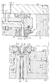
- Figure 3 is an enlarged sectional view of the cavity insert shown in Figures 1 and 2;
- Figure 4 is a partially cut-away view of the cavity insert seen in Figure 3 to show the cooling conduit configuration in this embodiment; and
- Figure 5 is a sectional view of a portion of an injection molding system showing a core insert according to a second embodiment of the invention.
- Reference is a first made to Figures 1 and 2 which show a portion of a multi-cavity thermal gated injection molding system having a number of heated
nozzles 10, each of which is received in anozzle plate 12 between acavity insert 14 and a commonelongated manifold 16. As seen in Figure 1, thecavity insert 14 is secured in position with itsrear end 18 abutting against theforward end 20 of thenozzle 10 by a cavityinsert retainer plate 22. The cavityinsert retainer plate 22 is held bybolts 24 which extend through thenozzle plate 12 to abackplate 26. - Each
nozzle 10 is attached bybolts 28 to themanifold 16 which is heated by anelectric heating element 30 which is integrally cast into it as described in the applicant's U.S. patent number 4,688,622 which issued August 25, 1987. Themanifold 16 is securely located in place between thenozzle plate 12 and thebackplate 26 by a central locatingring 32 and a number ofspacer rings 34. Thenozzle plate 12 and thebackplate 26 are cooled by pumping cooling water throughcooling conduits 36. The locatingring 32 provides aninsulative air space 38 between theheated manifold 16 and the coolednozzle plate 12. Thespacer rings 34 provide anotherinsulative air space 40 between theheated manifold 16 and the cooledbackplate 26. - The
manifold 16 has amelt passage 42 which branches from acommon inlet 44 to a number ofoutlets 46. Eachspacer ring 34 has astem portion 48 which extends into ahole 50 in themanifold 16. Thestem portion 48 has adiagonal face 52 which avoids a sharp corner in themelt passage 42. - In this embodiment, each
nozzle 10 has acentral melt passage 54 extending therethrough in alignment with one of theoutlets 46 from themelt passage 42 in themanifold 16. Thenozzle 10 is heated by an integral electrically insulatedheating element 56 which has ahelical portion 58 which encircles thecentral melt passage 54 and aterminal portion 60 which extends outwardly to anexternal terminal 62. The heatednozzle 10 has a circularouter collar portion 64 which forms anair gap 66 extending around thehelical portion 58 of theheating element 56 to reduce heat loss to the cavityinsert retainer plate 22. Aninsulative air space 68 is also provide around thenozzle 10 to reduce heat loss to the surroundingnozzle plate 12. Eachnozzle 10 also has athermocouple 70 to monitor the operating temperature adjacent theheating element 56. Thenozzle 10 is located by thecollar portion 64 being received in a matchingcircular seat 72 in cavityinsert retainer plate 22 so themelt passage 42 through thenozzle 10 is accurately aligned with acentral bore 74 which extends through thecavity insert 14. Thecavity insert 14 also has agate 76 leading to acavity 78, and thecentral bore 74 has atapered portion 80 adjacent thegate 76. In other embodiments, a number of melt passages can extend through each nozzle to a bore in the cavity insert 14. - As described in more detail below, the cavity insert 14 and the
adjacent core insert 82 are made to form thecavity 78 between them of a described shape and size. Thecore insert 82 is cooled by cooling water which flows through acentral cooling tube 84. Thecore insert 82 is located by a surrounding coreinsert retainer plate 86. A stripperring retaining plate 88 is secured to the coreinsert retainer plate 86 bybolts 90 to secure astripper ring 92 around a tapered portion 94 of thecore insert 82. Awater cooling ring 96 with sealing O-rings 98 extends around between thestripper ring 92 and the stripperring retaining plate 88. Figure 2 is a similar view to Figure 1 showing the apparatus partially assembled to clearly illustrate how theseparate nozzle 10 and cavity insert 14 fit together. - Reference is now made to Figures 3 and 4 to describe the
cavity insert 14 in more detail. In this embodiment, it has a generally cylindrical shape with a taperedcentral portion 100 extending between aninner portion 102 and anouter portion 104, all of which are made of steel. Theouter portion 104 is cooled by pumping cooling water through acooling channel 106 which extends around the taperedcentral portion 100. Thecooling channel 106 has a number of pie-shaped portions 108 which extend inwardly from outercircumferential portions 110, one of which is connected to acooling water inlet 112 and an adjacent one of which is connected to acooling water outlet 113. O-rings 114 extend around between theouter portion 104 of thecavity insert 14 and the surrounding cavityinsert retainer plate 22 to prevent leakage of the cooling water. Thecentral portion 100 as a number of outercircumferential grooves 116 which provide air insulation between it and the cooledouter portion 104. - The
cavity insert 14 also has an electrically insulatedheating element 118. In this embodiment, theheating element 118 has a nickel chromeresistant wire 120 extending through a refractory powder electricalinsulating material 122, such as magnesium oxide, in asteel casing 124. Theheating element 118 has anouter terminal portion 126 which extends outwardly from aninner portion 128 to anexternal terminal 130. Theouter terminal portion 126 has a generally uniform circular cross section, while theinner portion 128 has a generally uniform rectangular cross section. Theinner portion 128 of theheating elememt 118 is formed of a number ofadjacent coils 132. As described in detail in the applicant's Canadian patent application serial number 2,030,286 filed November 19, 1990 entitled "Injection Molding Nozzle having Tapered Heating Element Adjacent the Bore", theinner portion 128 is made by coiling a portion of a heating element and then compressing it in an opening in a tapered die. Thus, theadjacent coils 132 with the rectangular cross section form a taperedinner surface 134. After thecentral portion 100 of thecavity insert 14 is inserted into theouter portion 104, theheating element 118 is mounted with its centralinner portion 128 between the central and inner portions 100,102 of thecavity insert 14 and itsouter terminal portion 126 extending out through a slot (not shown) in theouter portion 104. The assembly is then brazed together in a vacuum furnace which provides a metallugical bonding of the parts into an integral unit. Thecentral portion 128 of theheating element 118 encircles thecentral bore 74 leading to thegate 76. In fact, in this embodiment of the invention, thetapered portion 80 of thecentral bore 74 extending through thecavity insert 14 to thegate 74 is provided bypart 136 of theinner surface 134 formed by the taperedadjacent coils 132 of theinner portion 128 of theheating element 118. Thecavity insert 14 also has athermocouple 137 to monitor the operating temperature adjacent theheating element 118. - In use, the system is assembled as shown in Figures 1 and 2 and electrical power is applied to the heating element of the manifold 16, the
heating elements 56 of thenozzles 10, and theheating elements 118 of the cavity inserts 14 to heat them to a predetermined operating temperature. Pressurized melt is injected from a molding machine (not shown) through theinlet 44 into themelt passage 42 in the manifold 16 according to a predetermined operating cycle. In order to provide thermal or temperature assisted gating, the power to theheating elements 118 of thecavity plates 14 is controlled in conjunction with the melt injection pressure. The pressurized melt flows through themelt channel 42, the melt passages in eachnozzle 10 andcavity insert 14, and thegates 76, and fills thecavities 78. After thecavities 78 are filled, the injection pressure is held momentarily to pack and then released. Following a short cooling period, the mold is opened along theparting line 138 to eject the molded products. The power to theheating elements 118 is switched off just before the mold is opened. The heat in the gate and cavity areas is quickly dissipated by the water flowing through the coolingchannel 106 and thegates 76 freeze off. Power is reapplied to theheating elements 118 as the mold is closed following ejection. This instantly heats the solidified melt in thegates 76 so they open immediately when melt injection pressure is reapplied. This cycle is repeated continuously as rapidly as several times per minute in some instances. The combination of both thecooling channel 106 and theheating element 118 extending around the tapered bore 74 of thecavity insert 14 improves thermal response and thus reduces cycle time. This is particularly true when part of theinner surface 134 formed by theadjacent coils 132 of theinner portion 128 of theheating element 118 provides the taperedportion 80 of thecentral bore 74 of thecavity insert 14. - Reference is now made to Figure 5 to describe a second embodiment of the invention. As many of the elements in this embodiment are similar to those of the first embodiment, elements common to both embodiments are described and illustrated using the same reference numerals. As can be seen, in this embodiment the
cavity 140 has a different shape than thecavity 78 of the first embodiment. Thus, acore insert 142 is required, rather than a cavity insert. As mentioned above, the generic term "cavity forming insert" is used herein to include both acavity insert 14 as described in the first embodiment and acore insert 142 as described in this embodiment. Thecore insert 142 is secured in place with itsrear end 144 abutting against theforward end 20 of thenozzle 10 by a coreinsert retainer plate 146 which is secured by bolts (not shown) which extend to thebackplate 26. - The
core insert 142 has asimilar heating element 148 with an outerterminal portion 150 and an inner portion 152 which extends around acentral bore 154 leading to a gate 156. The outerterminal portion 150 has a generally uniform circular cross section, whereas the cross section of the inner portion 152 is generally rectangular. As described above, the inner portion 152 of theheating element 148 is formed of a number ofadjacent coils 158, which form aninner surface 160. In this embodiment, thisinner surface 160 forms most of thecentral bore 154 through thecore insert 142 to provide immediate thermal response for thermal gating. Thecore insert 142 also has interconnected cooling bores 162 extending around thecentral bore 154 through which cooling water is pumped to provide cooling. - In use, heating and melt injection pressure are applied according to a predetermined thermal gating cycle similar to that described above, and the mold is opened along
parting line 164. The combination of heating and cooling in thecore insert 142 again improves thermal response and reduces cycle time. - While the description of the injection molding apparatus having a
cavity forming insert 14 with a combination of heating and cooling extending around thecentral bore 74 has been given with respect to preferred embodiments, it is not to be construed in a limiting sense. Variations will readily occur to those skilled in the art. For instance, it is apparent that the size and shape of the central bore and the size, shape and location of the cooling channel and heating element extending around it can be different for different applications. Reference is made to the appended claims for a definition of the invention.
Claims (1)
- In an injection molding apparatus to convey pressurized melt from a source to a cavity having a cooled cavity forming insert with a rear end, a heated nozzle with a forward end, the heated nozzle being received in a nozzle plate with the forward end of the heated nozzle abutting against the rear end of the cavity forming insert, the nozzle having at least one melt passage extending therethrough, the improvement wherein;
the cavity forming insert has a gate leading to the cavity, a central bore to convey melt from the melt passage in the nozzle to the gate, and an integral electrically insulated heating element, the heating element having an outer terminal portion extending outwardly to an external terminal and an inner portion having a generally uniform rectangular cross section, the inner portion of the heating element having a plurality of adjacent coils which form an inner surface, the heating element being integrally mounted in the cavity forming insert with the inner portion extending around the central bore leading to the gate whereby at least part of the inner surface formed by the adjacent coils of the inner portion of the heating element form a tapered portion of the central bore leading to the gate.
Applications Claiming Priority (2)
| Application Number | Priority Date | Filing Date | Title |
|---|---|---|---|
| CA002030287A CA2030287C (en) | 1990-11-19 | 1990-11-19 | Injection molding apparatus having separate heating element in the cavity forming insert |
| CA2030287 | 1990-11-19 |
Publications (3)
| Publication Number | Publication Date |
|---|---|
| EP0486968A2 true EP0486968A2 (en) | 1992-05-27 |
| EP0486968A3 EP0486968A3 (en) | 1992-09-02 |
| EP0486968B1 EP0486968B1 (en) | 1995-02-01 |
Family
ID=4146470
Family Applications (1)
| Application Number | Title | Priority Date | Filing Date |
|---|---|---|---|
| EP91119538A Expired - Lifetime EP0486968B1 (en) | 1990-11-19 | 1991-11-15 | Injection molding apparatus having separate heating element in the cavity forming insert |
Country Status (9)
| Country | Link |
|---|---|
| US (1) | US5061174A (en) |
| EP (1) | EP0486968B1 (en) |
| JP (1) | JP3004428B2 (en) |
| CN (1) | CN1033959C (en) |
| AT (1) | ATE117930T1 (en) |
| CA (1) | CA2030287C (en) |
| DE (2) | DE69107175T2 (en) |
| DK (1) | DK0486968T3 (en) |
| ES (1) | ES2067833T3 (en) |
Families Citing this family (20)
| Publication number | Priority date | Publication date | Assignee | Title |
|---|---|---|---|---|
| CA2030287C (en) * | 1990-11-19 | 2000-12-19 | Jobst Ulrich Gellert | Injection molding apparatus having separate heating element in the cavity forming insert |
| CA2032294A1 (en) * | 1990-12-17 | 1992-06-18 | Jobst Ulrich Gellert | Thermal valve gated injection molding apparatus with melt distribution plate |
| US5569475A (en) * | 1993-06-10 | 1996-10-29 | D-M-E Company | Insulator for thermoplastic molding nozzle assembly |
| US5423670A (en) * | 1993-10-08 | 1995-06-13 | Hamel; Julio E. | Enhanced thermal transfer injection molding apparatus |
| US5620635A (en) * | 1995-01-11 | 1997-04-15 | Derozier; Gaston | Ophthalmic lens manufacturing equipment and method |
| DE19611267C1 (en) * | 1996-03-22 | 1997-07-03 | Hotset Heizpatronen Zubehoer | Zinc diecasting machine |
| US5820900A (en) * | 1996-08-21 | 1998-10-13 | Mcgrevy; Alan N. | Heating device for an injection mold apparatus |
| US5871786A (en) * | 1997-04-04 | 1999-02-16 | Kona Corporation | Tip heated hot runner nozzle |
| CA2256090C (en) | 1998-12-14 | 2007-08-21 | Mold-Masters Limited | Injection molding apparatus having mold cores with reverse taper |
| IT248160Y1 (en) * | 1999-12-28 | 2002-12-10 | Sipa Spa | PERFECTED INJECTION MOLDS. |
| US6571192B1 (en) | 2000-11-28 | 2003-05-27 | W. Eric Hinshaw | Automatic mattress selection system |
| JP2004042601A (en) * | 2002-05-15 | 2004-02-12 | Meiki Co Ltd | Molding mold and molding method |
| KR100536771B1 (en) * | 2002-08-16 | 2005-12-14 | 유도실업주식회사 | Device and method for opening and closing noggle gate with heating and cooling device for hot runners of injection molding machines |
| CA2461461C (en) * | 2003-03-21 | 2011-05-24 | Mold-Masters Limited | Injection molding valve pin bushing |
| US7160100B2 (en) * | 2004-01-06 | 2007-01-09 | Mold-Masters Limited | Injection molding apparatus having an elongated nozzle incorporating multiple nozzle bodies in tandem |
| JP2005297566A (en) * | 2004-04-07 | 2005-10-27 | Mold Masters Ltd | Nozzle provided with nozzle body having heated nozzle body segment and unheated nozzle body segment |
| CA2482254A1 (en) | 2004-04-07 | 2005-10-07 | Mold-Masters Limited | Modular injection nozzle having a thermal barrier |
| US7914271B2 (en) * | 2007-11-29 | 2011-03-29 | Husky Injection Molding Systems Ltd. | Gate insert heating and cooling |
| CN103448213A (en) * | 2013-09-25 | 2013-12-18 | 常熟市金马模具有限公司 | Rapid cooling die |
| DE102016203995A1 (en) | 2016-03-10 | 2017-09-14 | Otto Männer Innovation GmbH | Hot runner system and associated nozzle heaters |
Citations (4)
| Publication number | Priority date | Publication date | Assignee | Title |
|---|---|---|---|---|
| EP0361043A2 (en) * | 1988-09-30 | 1990-04-04 | Jobst Ulrich Gellert | Injection molding nozzle having nose portion with heating element encircling the bore and method |
| US5046942A (en) * | 1990-11-19 | 1991-09-10 | Gellert Jobst U | Injection molding nozzle having tapered heating element adjacent the bore |
| US5061174A (en) * | 1990-11-19 | 1991-10-29 | Gellert Jobst U | Injection molding apparatus having separate heating element in the cavity forming insert |
| EP0374549B1 (en) * | 1988-12-05 | 1995-03-15 | Mold-Masters Limited | Injection molding apparatus having fluid cooled inserts |
Family Cites Families (4)
| Publication number | Priority date | Publication date | Assignee | Title |
|---|---|---|---|---|
| CA1174020A (en) * | 1982-01-06 | 1984-09-11 | Jobst U. Gellert | Injection molding manifold member and method of manufacture |
| US4622001A (en) * | 1985-03-12 | 1986-11-11 | Electra Form, Inc. | Cavity cooling system |
| CA1261573A (en) * | 1987-10-16 | 1989-09-26 | Harald H. Schmidt | Injection molding nozzle having grounded heating element brazed into pointed tip |
| CA1265909A (en) * | 1988-02-16 | 1990-02-20 | Jobst Ulrich Gellert | Injection molding heated gate insert and method |
-
1990
- 1990-11-19 CA CA002030287A patent/CA2030287C/en not_active Expired - Lifetime
- 1990-12-31 US US07/635,991 patent/US5061174A/en not_active Expired - Lifetime
-
1991
- 1991-11-13 JP JP3297156A patent/JP3004428B2/en not_active Expired - Fee Related
- 1991-11-15 ES ES91119538T patent/ES2067833T3/en not_active Expired - Lifetime
- 1991-11-15 AT AT91119538T patent/ATE117930T1/en not_active IP Right Cessation
- 1991-11-15 DE DE69107175T patent/DE69107175T2/en not_active Expired - Fee Related
- 1991-11-15 EP EP91119538A patent/EP0486968B1/en not_active Expired - Lifetime
- 1991-11-15 DE DE4137664A patent/DE4137664B4/en not_active Expired - Fee Related
- 1991-11-15 DK DK91119538.6T patent/DK0486968T3/en active
- 1991-11-16 CN CN91110705.3A patent/CN1033959C/en not_active Expired - Fee Related
Patent Citations (4)
| Publication number | Priority date | Publication date | Assignee | Title |
|---|---|---|---|---|
| EP0361043A2 (en) * | 1988-09-30 | 1990-04-04 | Jobst Ulrich Gellert | Injection molding nozzle having nose portion with heating element encircling the bore and method |
| EP0374549B1 (en) * | 1988-12-05 | 1995-03-15 | Mold-Masters Limited | Injection molding apparatus having fluid cooled inserts |
| US5046942A (en) * | 1990-11-19 | 1991-09-10 | Gellert Jobst U | Injection molding nozzle having tapered heating element adjacent the bore |
| US5061174A (en) * | 1990-11-19 | 1991-10-29 | Gellert Jobst U | Injection molding apparatus having separate heating element in the cavity forming insert |
Also Published As
| Publication number | Publication date |
|---|---|
| DE4137664B4 (en) | 2005-11-24 |
| CA2030287A1 (en) | 1992-05-20 |
| JPH05147089A (en) | 1993-06-15 |
| DK0486968T3 (en) | 1995-06-26 |
| CN1033959C (en) | 1997-02-05 |
| EP0486968A3 (en) | 1992-09-02 |
| EP0486968B1 (en) | 1995-02-01 |
| US5061174A (en) | 1991-10-29 |
| DE69107175T2 (en) | 1995-06-08 |
| CA2030287C (en) | 2000-12-19 |
| ATE117930T1 (en) | 1995-02-15 |
| DE69107175D1 (en) | 1995-03-16 |
| JP3004428B2 (en) | 2000-01-31 |
| CN1061560A (en) | 1992-06-03 |
| DE4137664A1 (en) | 1992-05-21 |
| ES2067833T3 (en) | 1995-04-01 |
Similar Documents
| Publication | Publication Date | Title |
|---|---|---|
| EP0486968B1 (en) | Injection molding apparatus having separate heating element in the cavity forming insert | |
| EP1137526B1 (en) | Injection molding cooling core having spiral grooves | |
| EP0486967B1 (en) | Injection molding nozzle having tapered heating element adjacent the bore | |
| EP0382888B1 (en) | Injection molding system having a valve member with a ribbed insulative portion | |
| EP0407971A2 (en) | Injection molding system with flanged insulation gate seal | |
| US20020117777A1 (en) | Injection molding cooled cavity insert | |
| US5952016A (en) | Side gated injection molding apparatus with actuated manifold | |
| EP0523549A2 (en) | Injection molding manifold with removable inserts | |
| EP0743159A1 (en) | Side gated injection molding apparatus with radially mounted gate inserts | |
| EP0337454A2 (en) | Injection molding system with nozzle in tandem | |
| EP1192035B1 (en) | Injection molding heater with melt bore therethrough | |
| EP0374549A2 (en) | Injection molding apparatus having fluid cooled inserts | |
| EP1137525B1 (en) | Injection molding cooling core having a ribbed cap | |
| EP0386309B1 (en) | Injection molding nozzle with self-supporting actuating mechanism | |
| EP0496284A2 (en) | Injection molding apparatus with integral cooling in a forward portion of the nozzle | |
| EP0638406B1 (en) | Injection molding nozzle which retains a thermocouple element | |
| CA2037186C (en) | Injection molding probe with a longitudinal thermocouple bore and off center heating element | |
| EP0960713A2 (en) | Injection molding apparatus having nozzles with elongated mounting flanges | |
| EP0842751A2 (en) | Injection molding nozzle with edge gate inserts and sealing ring | |
| EP0609676B1 (en) | Injection molding nozzle with thermocouple tube | |
| EP0743158A1 (en) | Injection molding hot tip side gate seal with circumferential rim | |
| US5142126A (en) | Injection molding manifold with integral heated inlet portion | |
| EP0422622A2 (en) | Injection molding insulated valve member | |
| EP0518120B1 (en) | Injection molding manifold with integral heated inlet portion | |
| EP0346900A2 (en) | Injection molding system with insertable insulating ring |
Legal Events
| Date | Code | Title | Description |
|---|---|---|---|
| PUAI | Public reference made under article 153(3) epc to a published international application that has entered the european phase |
Free format text: ORIGINAL CODE: 0009012 |
|
| AK | Designated contracting states |
Kind code of ref document: A2 Designated state(s): AT BE CH DE DK ES FR GB GR IT LI LU NL SE |
|
| PUAL | Search report despatched |
Free format text: ORIGINAL CODE: 0009013 |
|
| AK | Designated contracting states |
Kind code of ref document: A3 Designated state(s): AT BE CH DE DK ES FR GB GR IT LI LU NL SE |
|
| 17P | Request for examination filed |
Effective date: 19921016 |
|
| 17Q | First examination report despatched |
Effective date: 19940310 |
|
| GRAA | (expected) grant |
Free format text: ORIGINAL CODE: 0009210 |
|
| AK | Designated contracting states |
Kind code of ref document: B1 Designated state(s): AT BE CH DE DK ES FR GB GR IT LI LU NL SE |
|
| PG25 | Lapsed in a contracting state [announced via postgrant information from national office to epo] |
Ref country code: GR Free format text: LAPSE BECAUSE OF FAILURE TO SUBMIT A TRANSLATION OF THE DESCRIPTION OR TO PAY THE FEE WITHIN THE PRESCRIBED TIME-LIMIT Effective date: 19950201 |
|
| REF | Corresponds to: |
Ref document number: 117930 Country of ref document: AT Date of ref document: 19950215 Kind code of ref document: T |
|
| ITF | It: translation for a ep patent filed |
Owner name: MARCHI & MITTLER S.R.L. |
|
| REF | Corresponds to: |
Ref document number: 69107175 Country of ref document: DE Date of ref document: 19950316 |
|
| REG | Reference to a national code |
Ref country code: ES Ref legal event code: FG2A Ref document number: 2067833 Country of ref document: ES Kind code of ref document: T3 |
|
| ET | Fr: translation filed | ||
| REG | Reference to a national code |
Ref country code: DK Ref legal event code: T3 |
|
| PGFP | Annual fee paid to national office [announced via postgrant information from national office to epo] |
Ref country code: GB Payment date: 19951106 Year of fee payment: 5 |
|
| PGFP | Annual fee paid to national office [announced via postgrant information from national office to epo] |
Ref country code: DK Payment date: 19951108 Year of fee payment: 5 |
|
| PGFP | Annual fee paid to national office [announced via postgrant information from national office to epo] |
Ref country code: FR Payment date: 19951109 Year of fee payment: 5 |
|
| PGFP | Annual fee paid to national office [announced via postgrant information from national office to epo] |
Ref country code: AT Payment date: 19951113 Year of fee payment: 5 |
|
| PGFP | Annual fee paid to national office [announced via postgrant information from national office to epo] |
Ref country code: SE Payment date: 19951116 Year of fee payment: 5 |
|
| PGFP | Annual fee paid to national office [announced via postgrant information from national office to epo] |
Ref country code: CH Payment date: 19951122 Year of fee payment: 5 |
|
| PGFP | Annual fee paid to national office [announced via postgrant information from national office to epo] |
Ref country code: ES Payment date: 19951128 Year of fee payment: 5 |
|
| PGFP | Annual fee paid to national office [announced via postgrant information from national office to epo] |
Ref country code: LU Payment date: 19960101 Year of fee payment: 5 |
|
| PLBE | No opposition filed within time limit |
Free format text: ORIGINAL CODE: 0009261 |
|
| STAA | Information on the status of an ep patent application or granted ep patent |
Free format text: STATUS: NO OPPOSITION FILED WITHIN TIME LIMIT |
|
| PGFP | Annual fee paid to national office [announced via postgrant information from national office to epo] |
Ref country code: BE Payment date: 19960109 Year of fee payment: 5 |
|
| 26N | No opposition filed | ||
| PG25 | Lapsed in a contracting state [announced via postgrant information from national office to epo] |
Ref country code: DK Effective date: 19961115 Ref country code: GB Effective date: 19961115 Ref country code: AT Effective date: 19961115 Ref country code: LU Free format text: LAPSE BECAUSE OF NON-PAYMENT OF DUE FEES Effective date: 19961115 |
|
| REG | Reference to a national code |
Ref country code: DK Ref legal event code: EBP |
|
| PG25 | Lapsed in a contracting state [announced via postgrant information from national office to epo] |
Ref country code: SE Effective date: 19961116 Ref country code: ES Free format text: LAPSE BECAUSE OF NON-PAYMENT OF DUE FEES Effective date: 19961116 |
|
| PG25 | Lapsed in a contracting state [announced via postgrant information from national office to epo] |
Ref country code: CH Effective date: 19961130 Ref country code: BE Effective date: 19961130 Ref country code: LI Effective date: 19961130 |
|
| BERE | Be: lapsed |
Owner name: GELLERT JOBST ULRICH Effective date: 19961130 |
|
| GBPC | Gb: european patent ceased through non-payment of renewal fee |
Effective date: 19961115 |
|
| REG | Reference to a national code |
Ref country code: CH Ref legal event code: PL |
|
| PG25 | Lapsed in a contracting state [announced via postgrant information from national office to epo] |
Ref country code: FR Effective date: 19970731 |
|
| EUG | Se: european patent has lapsed |
Ref document number: 91119538.6 |
|
| REG | Reference to a national code |
Ref country code: FR Ref legal event code: ST |
|
| REG | Reference to a national code |
Ref country code: ES Ref legal event code: FD2A Effective date: 19971213 |
|
| PG25 | Lapsed in a contracting state [announced via postgrant information from national office to epo] |
Ref country code: IT Free format text: LAPSE BECAUSE OF NON-PAYMENT OF DUE FEES;WARNING: LAPSES OF ITALIAN PATENTS WITH EFFECTIVE DATE BEFORE 2007 MAY HAVE OCCURRED AT ANY TIME BEFORE 2007. THE CORRECT EFFECTIVE DATE MAY BE DIFFERENT FROM THE ONE RECORDED. Effective date: 20051115 |
|
| NLS | Nl: assignments of ep-patents |
Owner name: MOLD-MASTERS (2007) LIMITED Effective date: 20080610 |
|
| PGFP | Annual fee paid to national office [announced via postgrant information from national office to epo] |
Ref country code: NL Payment date: 20081028 Year of fee payment: 18 Ref country code: DE Payment date: 20081126 Year of fee payment: 18 |
|
| REG | Reference to a national code |
Ref country code: NL Ref legal event code: V1 Effective date: 20100601 |
|
| PG25 | Lapsed in a contracting state [announced via postgrant information from national office to epo] |
Ref country code: NL Free format text: LAPSE BECAUSE OF NON-PAYMENT OF DUE FEES Effective date: 20100601 |
|
| PG25 | Lapsed in a contracting state [announced via postgrant information from national office to epo] |
Ref country code: DE Free format text: LAPSE BECAUSE OF NON-PAYMENT OF DUE FEES Effective date: 20100601 |