EP0374549A2 - Injection molding apparatus having fluid cooled inserts - Google Patents
Injection molding apparatus having fluid cooled inserts Download PDFInfo
- Publication number
- EP0374549A2 EP0374549A2 EP89122225A EP89122225A EP0374549A2 EP 0374549 A2 EP0374549 A2 EP 0374549A2 EP 89122225 A EP89122225 A EP 89122225A EP 89122225 A EP89122225 A EP 89122225A EP 0374549 A2 EP0374549 A2 EP 0374549A2
- Authority
- EP
- European Patent Office
- Prior art keywords
- insert
- cooling fluid
- injection molding
- gate
- passage
- Prior art date
- Legal status (The legal status is an assumption and is not a legal conclusion. Google has not performed a legal analysis and makes no representation as to the accuracy of the status listed.)
- Granted
Links
- 238000001746 injection moulding Methods 0.000 title claims abstract description 23
- 239000012530 fluid Substances 0.000 title claims description 9
- 239000012809 cooling fluid Substances 0.000 claims abstract description 27
- 239000000523 sample Substances 0.000 claims abstract description 5
- 239000000155 melt Substances 0.000 claims description 17
- 238000001816 cooling Methods 0.000 claims description 10
- 108091092889 HOTTIP Proteins 0.000 claims description 3
- 230000006872 improvement Effects 0.000 claims description 2
- 238000010438 heat treatment Methods 0.000 abstract description 18
- 238000005219 brazing Methods 0.000 abstract description 10
- 239000012943 hotmelt Substances 0.000 abstract 1
- 238000003754 machining Methods 0.000 abstract 1
- XLYOFNOQVPJJNP-UHFFFAOYSA-N water Substances O XLYOFNOQVPJJNP-UHFFFAOYSA-N 0.000 description 9
- 229910000831 Steel Inorganic materials 0.000 description 8
- 239000000498 cooling water Substances 0.000 description 8
- 239000010959 steel Substances 0.000 description 8
- 229910000990 Ni alloy Inorganic materials 0.000 description 7
- 239000000463 material Substances 0.000 description 6
- 238000002347 injection Methods 0.000 description 5
- 239000007924 injection Substances 0.000 description 5
- 238000004519 manufacturing process Methods 0.000 description 5
- 238000007789 sealing Methods 0.000 description 5
- XKRFYHLGVUSROY-UHFFFAOYSA-N Argon Chemical compound [Ar] XKRFYHLGVUSROY-UHFFFAOYSA-N 0.000 description 4
- IJGRMHOSHXDMSA-UHFFFAOYSA-N Atomic nitrogen Chemical compound N#N IJGRMHOSHXDMSA-UHFFFAOYSA-N 0.000 description 4
- 238000002844 melting Methods 0.000 description 4
- 230000008018 melting Effects 0.000 description 4
- 238000000034 method Methods 0.000 description 4
- 238000000465 moulding Methods 0.000 description 4
- 238000005086 pumping Methods 0.000 description 4
- 239000011324 bead Substances 0.000 description 3
- 230000007246 mechanism Effects 0.000 description 3
- 230000001681 protective effect Effects 0.000 description 3
- PXHVJJICTQNCMI-UHFFFAOYSA-N Nickel Chemical compound [Ni] PXHVJJICTQNCMI-UHFFFAOYSA-N 0.000 description 2
- 229910001315 Tool steel Inorganic materials 0.000 description 2
- 230000009471 action Effects 0.000 description 2
- 229910052786 argon Inorganic materials 0.000 description 2
- QVGXLLKOCUKJST-UHFFFAOYSA-N atomic oxygen Chemical compound [O] QVGXLLKOCUKJST-UHFFFAOYSA-N 0.000 description 2
- 239000011248 coating agent Substances 0.000 description 2
- 238000000576 coating method Methods 0.000 description 2
- 238000005485 electric heating Methods 0.000 description 2
- 239000011261 inert gas Substances 0.000 description 2
- 239000011810 insulating material Substances 0.000 description 2
- 238000009413 insulation Methods 0.000 description 2
- 229910052757 nitrogen Inorganic materials 0.000 description 2
- 239000001301 oxygen Substances 0.000 description 2
- 229910052760 oxygen Inorganic materials 0.000 description 2
- 238000007711 solidification Methods 0.000 description 2
- 230000008023 solidification Effects 0.000 description 2
- 238000003466 welding Methods 0.000 description 2
- 229910000997 High-speed steel Inorganic materials 0.000 description 1
- RTAQQCXQSZGOHL-UHFFFAOYSA-N Titanium Chemical compound [Ti] RTAQQCXQSZGOHL-UHFFFAOYSA-N 0.000 description 1
- 230000001419 dependent effect Effects 0.000 description 1
- 230000009977 dual effect Effects 0.000 description 1
- CPLXHLVBOLITMK-UHFFFAOYSA-N magnesium oxide Inorganic materials [Mg]=O CPLXHLVBOLITMK-UHFFFAOYSA-N 0.000 description 1
- 239000000395 magnesium oxide Substances 0.000 description 1
- AXZKOIWUVFPNLO-UHFFFAOYSA-N magnesium;oxygen(2-) Chemical compound [O-2].[Mg+2] AXZKOIWUVFPNLO-UHFFFAOYSA-N 0.000 description 1
- 238000012986 modification Methods 0.000 description 1
- 230000004048 modification Effects 0.000 description 1
- 229910052759 nickel Inorganic materials 0.000 description 1
- 229920000515 polycarbonate Polymers 0.000 description 1
- 239000004417 polycarbonate Substances 0.000 description 1
- 125000006850 spacer group Chemical group 0.000 description 1
- 239000010936 titanium Substances 0.000 description 1
- 229910052719 titanium Inorganic materials 0.000 description 1
Images


Classifications
-
- B—PERFORMING OPERATIONS; TRANSPORTING
- B29—WORKING OF PLASTICS; WORKING OF SUBSTANCES IN A PLASTIC STATE IN GENERAL
- B29C—SHAPING OR JOINING OF PLASTICS; SHAPING OF MATERIAL IN A PLASTIC STATE, NOT OTHERWISE PROVIDED FOR; AFTER-TREATMENT OF THE SHAPED PRODUCTS, e.g. REPAIRING
- B29C45/00—Injection moulding, i.e. forcing the required volume of moulding material through a nozzle into a closed mould; Apparatus therefor
- B29C45/17—Component parts, details or accessories; Auxiliary operations
- B29C45/72—Heating or cooling
- B29C45/73—Heating or cooling of the mould
-
- B—PERFORMING OPERATIONS; TRANSPORTING
- B29—WORKING OF PLASTICS; WORKING OF SUBSTANCES IN A PLASTIC STATE IN GENERAL
- B29C—SHAPING OR JOINING OF PLASTICS; SHAPING OF MATERIAL IN A PLASTIC STATE, NOT OTHERWISE PROVIDED FOR; AFTER-TREATMENT OF THE SHAPED PRODUCTS, e.g. REPAIRING
- B29C45/00—Injection moulding, i.e. forcing the required volume of moulding material through a nozzle into a closed mould; Apparatus therefor
- B29C45/17—Component parts, details or accessories; Auxiliary operations
- B29C45/26—Moulds
- B29C45/27—Sprue channels ; Runner channels or runner nozzles
- B29C45/2737—Heating or cooling means therefor
-
- B—PERFORMING OPERATIONS; TRANSPORTING
- B29—WORKING OF PLASTICS; WORKING OF SUBSTANCES IN A PLASTIC STATE IN GENERAL
- B29C—SHAPING OR JOINING OF PLASTICS; SHAPING OF MATERIAL IN A PLASTIC STATE, NOT OTHERWISE PROVIDED FOR; AFTER-TREATMENT OF THE SHAPED PRODUCTS, e.g. REPAIRING
- B29C45/00—Injection moulding, i.e. forcing the required volume of moulding material through a nozzle into a closed mould; Apparatus therefor
- B29C45/17—Component parts, details or accessories; Auxiliary operations
- B29C45/26—Moulds
- B29C45/27—Sprue channels ; Runner channels or runner nozzles
- B29C2045/2759—Nozzle centering or guiding means
-
- B—PERFORMING OPERATIONS; TRANSPORTING
- B29—WORKING OF PLASTICS; WORKING OF SUBSTANCES IN A PLASTIC STATE IN GENERAL
- B29C—SHAPING OR JOINING OF PLASTICS; SHAPING OF MATERIAL IN A PLASTIC STATE, NOT OTHERWISE PROVIDED FOR; AFTER-TREATMENT OF THE SHAPED PRODUCTS, e.g. REPAIRING
- B29C45/00—Injection moulding, i.e. forcing the required volume of moulding material through a nozzle into a closed mould; Apparatus therefor
- B29C45/17—Component parts, details or accessories; Auxiliary operations
- B29C45/26—Moulds
- B29C45/27—Sprue channels ; Runner channels or runner nozzles
- B29C2045/2761—Seals between nozzle and mould or gate
Definitions
- This invention relates generally to injection molding and more particularly to an injection molding system having an insert with a circular cooling fluid passage which cools the insert around the gate.
- the heating and cooling relationship is critical to the successful operation of some valve gated injection molding systems, particularly for molding temperature critical materials such as polycarbonate.
- the invention provides an injection molding system having at least one heated probe or nozzle which has a forward nose portion extending into a central well in an insert with a space provided between the nose portion and the surrounding insert, the nose portion being in alignment with a gate extending through the insert to a cavity, the system having a melt passage extending from an inlet to convey melt to the gate to fill the cavity, wherein the improvement comprises the insert has a cooling fluid passage extending therethrough around the forward nose portion adjacent the cavity, the cooling fluid passage extending from inlet and outlet cooling fluid ducts which connect respectively to high and low pressure cooling fluid conduits, whereby cooling fluid flows through the passage to provide cooling to the insert around the gate.
- FIG. 1 shows a portion of a multi-cavity injection molding system according to a first embodiment of the invention having a number of heated nozzles 10 extending from a common elongated heated manifold 12.
- Each heated nozzle 10 extends through an opening 14 in a support plate 16 into in a well 17 in a cooled mold core insert 18.
- the nozzle 10 has a steel cylindrical portion 20 with a generally cylindrical outer surface 22 extending between a steel collar portion 24 adjacent the rear end 26 and a steel elongated nose portion 28.
- the nose portion 28 has a tapered outer surface 30 which leads to a pointed tip 32 which is in alignment with a gate 34 through the mold core insert 18 leading to a cavity 36.
- the nozzle 10 is seated in this position by a circumferential insulating flange or bushing 38 which extends from the collar portion 24 and sits on a circumferential shoulder 40.
- the nozzle is accurately located with the pointed tip 32 in alignment with the gate 34 by a circumferential sealing and locating flange 42 which extends between the central portion 20 and the nose portion 28 to abut against the inner surface 44 of the well 17.
- the heated nozzle 10 is separated from the surrounding cooled support plate 16 and mold core insert 18 by an insulative air space 46.
- Each nozzle 10 is fastened by bolts 48 to the manifold 12 which is secured between the support plate 16 and a top clamp plate 50 by a locating ring 52 and a titanium pressure pad 54.
- the top clamp plate 50 is held in place by bolts 56 which extend into the support plate 16.
- the back plate 50, support plate 16 and mold core insert 18 are cooled by pumping cooling water through cooling conduits 58 as described in more detail below.
- the manifold 12 is heated by an electric heating element 60 which is cast into it as described in the applicant's U.S. patent number 4,688,622 entitled "Injection Molding Manifold Member and Method of Manufacture" which issued August 25, 1987.
- the locating ring 52 provides another insulative air space 62 between the heated manifold 12 and the cooled support plate 16.
- the manifold 12 has a melt passage 64 which branches from a common inlet to a number of outlets 66 on the opposite side. Each outlet is in alignment with an inlet 68 to a melt bore 70 extending through one of the nozzles. Each melt bore 70 has a central portion 72 extending from the rear end 26 and a diagonal portion 74, which extends to the tapered surface 30 of the nose portion 28.
- the nozzle 10 is heated by an electrically insulated heating element 76 having a longitudinal portion 78 which extends centrally in the nose portion 28, a helical portion 80 wound in a spiral channel 82 in the outer surface 22 of the cylindrical portion 20, and a diagonal portion 84 which extends into the nose portion 28 of the nozzle 10 beneath the circumferential sealing and locating flange 42 to connect the longitudinal portion 78 to the helical portion 80.
- the heating element 76 has a central resistance wire extending through an electrical insulating material inside a steel casing and the resistance wire is grounded adjacent a tool steel insert portion 86 which forms the pointed tip 32.
- the longitudinal portion 78 of the heating element is bent back upon itself to form double and triple thickness parts 88,90.
- the portion 80 of the heating element 76 in the channel 82 is covered by a protective nickel coating 92 which is applied as described in the applicant's U.S. patent number 4,768,283 which issued September 6, 1988.
- the heating element 76 also has a rear end portion 94 which extends outwardly from the collar portion 24 to an electrical terminal 96 which is made by a method described in detail in the applicant's Canadian patent application serial number 578,975 filed September 30, 1988 entitled "Method of Manufacture of an Electrical Terminal on an Injection Molding Nozzle".
- the rear end portion 94 extends through a terminal body 98 with a protective cap 100 which is fixed to a steel plug 102.
- the heating element 70 is stripped adjacent the rear end to expose the resistance wire 104 which is electrically connected to the terminal body 98.
- the terminal body 98 is electrically insulated from the heating element casing and the protective cap 100 by a thin coating 106 of insulating material such as magnesium oxide.
- the terminal body 98 is structurally secured to withstand torque as an external lead 108 is connected to it or disconnected from it by nuts 110.
- the mold core insert 18 has an inner portion 112 and an outer portion 114 which are shown separated in Figure 2, but are in fact integrally brazed together as described in more detail below.
- the inner portion 112 is made of H13 steel with the central well 17 leading to the gate 34.
- the inner surface 44 of the well 17 has a cylindrical portion 116 which receives the sealing and locating flange 42 to prevent leakage of melt from a space 118 between the outer surface 30 of the nose portion 28 and the inner surface 44 of the well 17.
- the inner portion 112 of each mold core insert has a pair of bores 120,122 which extend rearwardly from a circumferential shoulder 124 on opposite sides of the well 17.
- the outer portion 114 of the mold core insert 18 is made of high speed steel.
- the outer portion 114 has a central opening 126 therethrough and fits over the inner portion 112 to abut against the circumferential shoulder 124.
- the inner surface 128 of the outer portion 114 matches the abutting outer surface 130 of the inner portion except that the inner surface 128 of the outer portion 114 has a pair of channels 132,134 which extend rearwardly from a circular channel 136 adjacent the forward end 138 of the outer portion 114.
- the outer surface 140 of the outer portion 114 of the mold core insert 18 partially defines the cavity 36 which has a concave configuration.
- the circular channel 136 forms a circular cooling fluid passage 142 between the inner and outer portions 112,114 which extend around the nose portion 28 of the nozzle 10 adjacent the cavity 36.
- the channels 132,134 in the inner surface 128 of the outer portion 114 align and connect respectively with the bores 120,122 through the inner portion 112 and with rearwardly extending bores 144,146 in the support plate 16 to form inlet and outlet cooling fluid ducts 148,150.
- These ducts 148,150 extend respectively from high and low pressure conduits 152,154 to opposite sides of the circular passage 142 to provide a flow of cooling fluid such as water, through the circular passage.
- the rate of flow of cooling fluid through the passage is controlled to dissipate heat at a predetermined rate which otherwise accumulates from the friction of the melt and from the heating element 76 in the nose portion 28 of the nozzle 10.
- Resilient O-rings 156 are seated in circular grooves 158 which extend around the bores 120,122 in the rear face 160 of the inner portion 112 of the mold core insert 18 to prevent leakage of cooling fluid between the support plate 16 and the mold core insert 18.
- a stripper plate 162 engages a circular stripper ring 164 which projects rearwardly of the cavity 36 to eject the molded component when the mold is opened along the parting line 166.
- the space 118 remains filled with melt, a portion of which solidifies adjacent the mold core insert 18 and the sealing and locating flange 42 prevents it escaping in to the insulative air space 46.
- injection pressure is held momentarily to pack and then released.
- the mold is opened to eject the molded products.
- the mold is closed and injection pressure is reapplied to refill the cavity.
- the cycle is continuously repeated with a frequency dependent on the size and shape of the cavities and the type of material being molded.
- a continuous flow of cooling water is provided by pumping water through the high and low pressure conduits 152,154 extending through the support plate 16.
- This flow of cooling water prevents the build up of excess heat which otherwise occurs in the mold core insert 18 in the confined area between the space 118 around the nose portion 28 and the surrounding cavity 36.
- the rate of flow of water through the circular passage 142 is controlled to remove a suitable amount of heat for any particular application.
- the inlet ducts can be located side by side with a baffle between where they join the circular passage. This results in the water flowing around the circular passage all in the same direction.
- the inner and outer portions 112,114 are made as shown with the bores 120,122, and channels 132,134,136 of a matching size machined in predetermined locations.
- a bead of nickel alloy brazing paste is run around the outer surface 130 of the inner portion 112 and the inner and outer portions 112,114 are then fitted together with the bores 120,122 aligned with the respective channels 132,134. After tack welding them together to maintain this alignment, the assembled portions 112,114 are loaded in batches into a vacuum furnace. As the furnace is gradually heated to a temperature in excess of the melting point of the brazing material, the furnace is evacuated to a relatively high vacuum to remove substantially all of the oxygen.
- the vacuum is reduced by partially back filling with an inert gas such as argon or nitrogen.
- an inert gas such as argon or nitrogen.
- a multi-cavity valve gated injection molding system has an elongated manifold 12 extending between a back plate 170 and a number of nozzle 10.
- Each heated nozzle 10 is seated in a well 172 in a cooled gate insert 174 which is received in a cavity plate 176.
- Each nozzle 10 is heated by a helical electric heating element 76 which is integrally cast into it, and the back plate 170 and cavity plate 176 are cooled by pumping cooling water through cooling conduits 178.
- the nozzle 10 has an insulation bushing 38 which sits against an inwardly projecting shoulder 180 in the gate insert 174. This locates the nozzle 10 with its central bore 70 in alignment with a gate 34 leading to the cavity 36 and provides an insulative air space 182 between the heated nozzle 10 and the surrounding cooled gate insert 174.
- the gate 34 is provided by a nozzle seal 184 which bridges the air space 182 between the heated nozzle 10 and the cooled gate insert 174.
- Each valve member bushing 186 has a central bore 204 extending therethrough in alignment with the central bore 70 of the adjacent nozzle 10.
- An elongated valve member 206 extends through the aligned bores 70 and 204 of the nozzle 10 and bushing 186.
- the valve member 206 has an enlarged head 208 at its rear end and a tapered tip 210 at its forward end.
- the head 208 of the valve member 206 is engaged by valve member actuating mechanism which is seated in the back plate 170 to reciprocate the valve member 206 between a retracted open position and a forward closed position in which the tapered tip 210 is seated in the gate 34.
- the actuating mechanism includes a piston 212 which reciprocates in a cylinder 214.
- the valve member 206 extends through the piston 212 and the enlarged head 208 is secured to it by a cap 216 as described in the applicant's U.S. patent number 4,698,013 which issued October 6, 1987.
- This piston 212 has an elongated neck portion 218 which protrudes out through a V-shaped high pressure seal 220 which is seated in the cylinder 214 to prevent leakage of pressurized hydraulic fluid.
- the actuating mechanism is driven by pressurized hydraulic fluid through fluid lines 222,224 which extend through a back cover plate 226.
- the back cover plate 226, back plate 170 and a spacer plate 228 are secured together by bolts 230 which extend into the cavity plate 176.
- a melt passage 64 branches in the elongated manifold 12 to convey melt received from a molding machine (not shown) at a common inlet 232 to the central bore 70 of each nozzle 10 which leads to a respective cavity 36.
- the diameter of the central bore 70 of the nozzle 10 is sufficiently larger than the outside diameter of the valve member 206 extending centrally therethrough to form part of the melt passage 64.
- Each valve member bushing 186 also has a melt duct 234 which extends inwardly to connect the melt passage 64 in the manifold to the central bore 70, as described in detail in the applicant's Canadian patent application serial number filed June 30, 1989 entitled "Injection Molding System Having Dual Feed Bushing Seated in Manifold".
- each gate insert 174 has an inner portion 236 and an outer portion 238 which are integrally brazed together.
- both the inner and outer portions 236,238 are made of hot work tool steel.
- the outer portion 238 of the gate insert 174 has a central opening 240 therethrough which receives the inner portion 236.
- the inner surface 242 of the outer portion 238 matches the outer surface 244 of the inner portion 236 except that the outer surface 244 of the inner portion 236 has a pair of channels 246,248 extending rearwardly from a circular channel 250 adjacent the forward end 252 of the inner portion 236.
- the circular channel 250 forms a circular cooling fluid passage 256 which extends in the gate insert 174 around the nose portion 28 of the nozzle 10 adjacent the cavity 36.
- the channels 246,248 align with bores 258,260 through the outer portion 238 to form inlet and outlet cooling fluid ducts 262,264.
- These ducts 262,264 extend respectively from high and low pressure conduits to the circular passage 256 to provide a flow of cooling fluid such as water, through the circular passage.
- the rate of flow of cooling fluid through the passage 256 is controlled to dissipate heat at a predetermined rate which otherwise accumulates from the friction of the melt and from the heating element 76 in the nose portion 28 of the nozzle 10.
- the system is assembled as shown and electrical power is applied to the heating elements 76,60 to heat the nozzle 10 and manifold 12 to a predetermined operating temperature.
- Thermal expansion of the elongated manifold 12 brings the central bore 204 of the bushing 186 into accurate alignment with the central bore 70 of the nozzle 10 and the force from the back plate 170 against the circular flange 190 of the bushing 186 prevents leakage between the nozzle and bushing and retains the nozzle 10 firmly in place.
- Hot pressurized melt is injected from a molding machine (not shown) into the melt passage 64 through the central inlet 232 according to a predetermined cycle.
- Controlled hydraulic fluid pressure is applied to the cylinders 214 through fluid lines 222,224 to simultaneously control actuation of the valve members 206 according to a predetermined cycle in a conventional manner.
- the pressurized melt flows through the melt passage 64 and the gates 34 until the cavities 36 are full.
- injection pressure is held momentarily to pack.
- the hydraulic pressure is then reversed to reciprocate the valve member 206 to the forward closed position in which the tip 210 of one of the valve members 206 is seated in each of the gates 34.
- the injection pressure is then released and, after a short cooling period, the mold is opened for ejection.
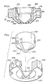
- a continuous flow of cooling water is provided by pumping water through high and low pressure conduits which connect to the inlet and outlet ducts 262,264 leading to the circular passage 256 on opposite sides of the baffle 254. As seen in Figure 6, the cooling water flows in the inlet duct 262, around the circular passage 256, and back out the outlet duct 264. This flow of cooling water prevents the build up of excess heat which otherwise occurs in the gate insert 174 in the area adjacent the space 182 around the nose portion 28. Of course, the rate of flow of water through the circular passage 256 is controlled to remove a suitable amount of heat for any particular application.
- the inner and outer portions 236,238 are made as shown with the channels 246,248,250 and bores 258,260 of a matching size machined in predetermined locations.
- the wedge shaped baffle 254 is tack welded into place in the circular channel 250 between where the pair of rearwardly extending channels 246,248 join it.
- a bead 266 of nickel alloy brazing paste is run around the circular channel 250 and the inner and outer portions 236,238 are then fitted together with the channels 246,248 in the inner portion 236 aligned with the matching bores 258,260 extending through the outer portion 238.
- each gate insert 174 having the groove 270 is then machined off to provide a flat rear face 272.
- the outer surface 274 of the outer portion 238 is also machined to provide the shape seen in Figure 3.
Abstract
Description
- This invention relates generally to injection molding and more particularly to an injection molding system having an insert with a circular cooling fluid passage which cools the insert around the gate.
- As is well known, the relationship between heating and cooling is critical to the successful operation of an injection molding system. It is increasingly important to reduce cycle time, and usually the largest impediment in doing so is the speed of solidification in the gate area. In order to improve solidification speed it is necesaary to remove or offset heat from the hot nozzle and friction heat from the material. This is particularly true in a hot tip gating system having a number of heated nozzles or probes arranged to mold components such as caps or closures with inside gates where the heat accumulates in the mold core in the area around the gate surrounded by the cavity. Each nozzle has a heated nose portion as described in Canadian patent application serial no. 563,981 to Gellert filed April 13, 1988 entitled "Injection Molding Nozzle having Multiple Thickness Heating Element and Method of Manufacture" to provide sufficient heat to the melt passing through the gate and it is difficult for this heat to escape to the surrounding cooled mold in view of the configuration of the cavity.
- Similarly, the heating and cooling relationship is critical to the successful operation of some valve gated injection molding systems, particularly for molding temperature critical materials such as polycarbonate.
- Accordingly, it is an object of the present invention to at least partially overcome the disadvantages of the prior art by providing additional cooling to the insert around the gate.
- To this end, in one of its aspects, the invention provides an injection molding system having at least one heated probe or nozzle which has a forward nose portion extending into a central well in an insert with a space provided between the nose portion and the surrounding insert, the nose portion being in alignment with a gate extending through the insert to a cavity, the system having a melt passage extending from an inlet to convey melt to the gate to fill the cavity, wherein the improvement comprises the insert has a cooling fluid passage extending therethrough around the forward nose portion adjacent the cavity, the cooling fluid passage extending from inlet and outlet cooling fluid ducts which connect respectively to high and low pressure cooling fluid conduits, whereby cooling fluid flows through the passage to provide cooling to the insert around the gate.
- Further objects and advantages of the invention will appear from the following description taken together with the accompanying drawings.
-
- Figure 1 is a sectional view of a portion of a typical injection molding system having a mold core insert with a circular fluid passage according to one embodiment of the invention,
- Figure 2 is an exploded isometric view illustrating how the mold core insert is made,
- Figure 3 is section view of a portion of a valve gated injection molding system having a gate insert with a circular fluid passage according to another embodiment of the invention,
- Figure 4 is an exploded isometric view,
- Figure 5 is an assembled sectional view of the gate insert illustrating how it is made, and
- Figure 6 is a schematic sectional view of the gate insert illustrating the flow pattern of the cooling water.
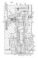
- Reference is first made to Figure 1 which shows a portion of a multi-cavity injection molding system according to a first embodiment of the invention having a number of heated
nozzles 10 extending from a common elongatedheated manifold 12. Each heatednozzle 10 extends through anopening 14 in asupport plate 16 into in a well 17 in a cooledmold core insert 18. Thenozzle 10 has a steel cylindrical portion 20 with a generally cylindricalouter surface 22 extending between asteel collar portion 24 adjacent therear end 26 and a steelelongated nose portion 28. Thenose portion 28 has a taperedouter surface 30 which leads to apointed tip 32 which is in alignment with agate 34 through themold core insert 18 leading to acavity 36. - The
nozzle 10 is seated in this position by a circumferential insulating flange or bushing 38 which extends from thecollar portion 24 and sits on a circumferential shoulder 40. The nozzle is accurately located with thepointed tip 32 in alignment with thegate 34 by a circumferential sealing and locating flange 42 which extends between the central portion 20 and thenose portion 28 to abut against the inner surface 44 of thewell 17. As can be seen, other than theinsulation flange 38 and the sealing and locating flange 42, the heatednozzle 10 is separated from the surrounding cooledsupport plate 16 andmold core insert 18 by aninsulative air space 46. - Each
nozzle 10 is fastened bybolts 48 to themanifold 12 which is secured between thesupport plate 16 and atop clamp plate 50 by a locatingring 52 and atitanium pressure pad 54. Thetop clamp plate 50 is held in place bybolts 56 which extend into thesupport plate 16. Theback plate 50,support plate 16 andmold core insert 18 are cooled by pumping cooling water throughcooling conduits 58 as described in more detail below. Themanifold 12 is heated by anelectric heating element 60 which is cast into it as described in the applicant's U.S. patent number 4,688,622 entitled "Injection Molding Manifold Member and Method of Manufacture" which issued August 25, 1987. The locatingring 52 provides anotherinsulative air space 62 between theheated manifold 12 and the cooledsupport plate 16. - The
manifold 12 has amelt passage 64 which branches from a common inlet to a number of outlets 66 on the opposite side. Each outlet is in alignment with aninlet 68 to amelt bore 70 extending through one of the nozzles. Eachmelt bore 70 has a central portion 72 extending from therear end 26 and adiagonal portion 74, which extends to thetapered surface 30 of thenose portion 28. - The
nozzle 10 is heated by an electrically insulatedheating element 76 having alongitudinal portion 78 which extends centrally in thenose portion 28, a helical portion 80 wound in aspiral channel 82 in theouter surface 22 of the cylindrical portion 20, and adiagonal portion 84 which extends into thenose portion 28 of thenozzle 10 beneath the circumferential sealing and locating flange 42 to connect thelongitudinal portion 78 to the helical portion 80. In this low voltage single wire heating element embodiment, theheating element 76 has a central resistance wire extending through an electrical insulating material inside a steel casing and the resistance wire is grounded adjacent a toolsteel insert portion 86 which forms thepointed tip 32. As described in Canadian patent application serial number 563,981 referred to above, in this embodiment, thelongitudinal portion 78 of the heating element is bent back upon itself to form double andtriple thickness parts heating element 76 in thechannel 82 is covered by aprotective nickel coating 92 which is applied as described in the applicant's U.S. patent number 4,768,283 which issued September 6, 1988. Theheating element 76 also has arear end portion 94 which extends outwardly from thecollar portion 24 to anelectrical terminal 96 which is made by a method described in detail in the applicant's Canadian patent application serial number 578,975 filed September 30, 1988 entitled "Method of Manufacture of an Electrical Terminal on an Injection Molding Nozzle". Therear end portion 94 extends through a terminal body 98 with aprotective cap 100 which is fixed to asteel plug 102. Theheating element 70 is stripped adjacent the rear end to expose theresistance wire 104 which is electrically connected to the terminal body 98. However the terminal body 98 is electrically insulated from the heating element casing and theprotective cap 100 by a thin coating 106 of insulating material such as magnesium oxide. Thus, the terminal body 98 is structurally secured to withstand torque as anexternal lead 108 is connected to it or disconnected from it bynuts 110. - The
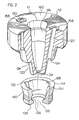
mold core insert 18 has aninner portion 112 and an outer portion 114 which are shown separated in Figure 2, but are in fact integrally brazed together as described in more detail below. In this embodiment, theinner portion 112 is made of H13 steel with thecentral well 17 leading to thegate 34. The inner surface 44 of thewell 17 has acylindrical portion 116 which receives the sealing and locating flange 42 to prevent leakage of melt from aspace 118 between theouter surface 30 of thenose portion 28 and the inner surface 44 of thewell 17. Theinner portion 112 of each mold core insert has a pair of bores 120,122 which extend rearwardly from acircumferential shoulder 124 on opposite sides of thewell 17. In this embodiment, the outer portion 114 of themold core insert 18 is made of high speed steel. - As seen in Figure 2, the outer portion 114 has a
central opening 126 therethrough and fits over theinner portion 112 to abut against thecircumferential shoulder 124. Theinner surface 128 of the outer portion 114 matches the abuttingouter surface 130 of the inner portion except that theinner surface 128 of the outer portion 114 has a pair of channels 132,134 which extend rearwardly from acircular channel 136 adjacent theforward end 138 of the outer portion 114. Theouter surface 140 of the outer portion 114 of themold core insert 18 partially defines thecavity 36 which has a concave configuration. - When the inner and outer portions 112,114 are integrally joined together to form the
mold core insert 18 and assembled in the system as shown in Figure 1, thecircular channel 136 forms a circularcooling fluid passage 142 between the inner and outer portions 112,114 which extend around thenose portion 28 of thenozzle 10 adjacent thecavity 36. Similarly, the channels 132,134 in theinner surface 128 of the outer portion 114 align and connect respectively with the bores 120,122 through theinner portion 112 and with rearwardly extending bores 144,146 in thesupport plate 16 to form inlet and outlet cooling fluid ducts 148,150. These ducts 148,150 extend respectively from high and low pressure conduits 152,154 to opposite sides of thecircular passage 142 to provide a flow of cooling fluid such as water, through the circular passage. The rate of flow of cooling fluid through the passage is controlled to dissipate heat at a predetermined rate which otherwise accumulates from the friction of the melt and from theheating element 76 in thenose portion 28 of thenozzle 10. Resilient O-rings 156 are seated incircular grooves 158 which extend around the bores 120,122 in therear face 160 of theinner portion 112 of themold core insert 18 to prevent leakage of cooling fluid between thesupport plate 16 and themold core insert 18. Astripper plate 162 engages acircular stripper ring 164 which projects rearwardly of thecavity 36 to eject the molded component when the mold is opened along theparting line 166. - In use, after the injection molding system has been assembled as shown in Figure 1 and described above, electrical power is applied through the
lead 108 to theheating element 76 in eachnozzle 10 and to theheating element 60 in themanifold 12 to heat thenozzle 10 and the manifold to a predetermined operating temperature. Pressurized melt from a molding machine (not shown) is then introduced into themelt passage 64 in themanifold 12 according to a predetermined cycle in a conventional manner. The pressurized melt flows through the melt bore 70 in eachnozzle 10 into thespace 118 surrounding thetapered surface 30 of thenose portion 28, and then through thegate 34 and fills thecavity 36. Thespace 118 remains filled with melt, a portion of which solidifies adjacent the mold core insert 18 and the sealing and locating flange 42 prevents it escaping in to theinsulative air space 46. After the cavities are filled, injection pressure is held momentarily to pack and then released. After a short cooling period, the mold is opened to eject the molded products. After ejection, the mold is closed and injection pressure is reapplied to refill the cavity. The cycle is continuously repeated with a frequency dependent on the size and shape of the cavities and the type of material being molded. A continuous flow of cooling water is provided by pumping water through the high and low pressure conduits 152,154 extending through thesupport plate 16. This water which flows in through each inlet duct 148, splits and flows around both sides of thecircular passage 142 in themold core insert 18 and back out throughoutlet duct 150. This flow of cooling water prevents the build up of excess heat which otherwise occurs in the mold core insert 18 in the confined area between thespace 118 around thenose portion 28 and the surroundingcavity 36. Of course, the rate of flow of water through thecircular passage 142 is controlled to remove a suitable amount of heat for any particular application. - While, in this embodiment, the water flow through the
circular passage 142 splits around each side, in an alternate embodiment the inlet ducts can be located side by side with a baffle between where they join the circular passage. This results in the water flowing around the circular passage all in the same direction. - The method of making the
mold core insert 18 will now be described with particular reference to Figure 2. The inner and outer portions 112,114 are made as shown with the bores 120,122, and channels 132,134,136 of a matching size machined in predetermined locations. A bead of nickel alloy brazing paste is run around theouter surface 130 of theinner portion 112 and the inner and outer portions 112,114 are then fitted together with the bores 120,122 aligned with the respective channels 132,134. After tack welding them together to maintain this alignment, the assembled portions 112,114 are loaded in batches into a vacuum furnace. As the furnace is gradually heated to a temperature in excess of the melting point of the brazing material, the furnace is evacuated to a relatively high vacuum to remove substantially all of the oxygen. Before the melting temperature of the brazing paste is reached, the vacuum is reduced by partially back filling with an inert gas such as argon or nitrogen. when the nickel alloy melts it flows by capillary action between the matching inner and outer surfaces 128,130 of the inner and outer portions 112,114 of themold core 18. This forms a strong integral mold core insert 18 with the desiredcircular passage 142 and inlet and outlet ducts 148,150 because brazing in a vacuum furnace provides a metallurgical bonding of the nickel alloy to the steel, and does not interfere with heat transfer between the two portions 112,114. - Reference is now made to Figure 3 which shows another embodiment of the invention. Elements which are common to both embodiments are described and illustrated using the same reference numerals. In this embodiment, a multi-cavity valve gated injection molding system has an elongated
manifold 12 extending between aback plate 170 and a number ofnozzle 10. Eachheated nozzle 10 is seated in a well 172 in a cooledgate insert 174 which is received in acavity plate 176. Eachnozzle 10 is heated by a helicalelectric heating element 76 which is integrally cast into it, and theback plate 170 andcavity plate 176 are cooled by pumping cooling water through coolingconduits 178. Thenozzle 10 has aninsulation bushing 38 which sits against an inwardly projecting shoulder 180 in thegate insert 174. This locates thenozzle 10 with itscentral bore 70 in alignment with agate 34 leading to thecavity 36 and provides aninsulative air space 182 between theheated nozzle 10 and the surrounding cooledgate insert 174. In this embodiment, thegate 34 is provided by anozzle seal 184 which bridges theair space 182 between theheated nozzle 10 and the cooledgate insert 174. - A
valve member bushing 186 is received in anopening 188 extending through theelongated manifold 12 in alignment with each of thenozzles 10. Eachvalve member bushing 186 has an outer flange 190 which extends into contact against thefront surface 192 of theback plate 170 and afront face 194 which abuts against therear face 196 of thenozzle 10. Eachvalve member bushing 186 also has a circumferential shoulder 198 which bears against therear surface 200 of the manifold 12. Thus, the manifold is accurately located between thecentral locating ring 52 seated in thecavity plate 176 and therear face 196 of the nozzle and the circumferential shoulder 198 of thebushings 36. This providesinsulative air spaces 202 between the manifold 12 which is heated by an integralelectrical heating element 60 and the cooled backplate 170 and thecavity plate 176. - Each
valve member bushing 186 has acentral bore 204 extending therethrough in alignment with thecentral bore 70 of theadjacent nozzle 10. Anelongated valve member 206 extends through the aligned bores 70 and 204 of thenozzle 10 andbushing 186. Thevalve member 206 has an enlarged head 208 at its rear end and a taperedtip 210 at its forward end. The head 208 of thevalve member 206 is engaged by valve member actuating mechanism which is seated in theback plate 170 to reciprocate thevalve member 206 between a retracted open position and a forward closed position in which the taperedtip 210 is seated in thegate 34. In this embodiment, the actuating mechanism includes apiston 212 which reciprocates in acylinder 214. Thevalve member 206 extends through thepiston 212 and the enlarged head 208 is secured to it by a cap 216 as described in the applicant's U.S. patent number 4,698,013 which issued October 6, 1987. Thispiston 212 has an elongatedneck portion 218 which protrudes out through a V-shapedhigh pressure seal 220 which is seated in thecylinder 214 to prevent leakage of pressurized hydraulic fluid. The actuating mechanism is driven by pressurized hydraulic fluid through fluid lines 222,224 which extend through a back cover plate 226. The back cover plate 226, backplate 170 and a spacer plate 228 are secured together bybolts 230 which extend into thecavity plate 176. - A
melt passage 64 branches in theelongated manifold 12 to convey melt received from a molding machine (not shown) at acommon inlet 232 to thecentral bore 70 of eachnozzle 10 which leads to arespective cavity 36. As can be seen, the diameter of thecentral bore 70 of thenozzle 10 is sufficiently larger than the outside diameter of thevalve member 206 extending centrally therethrough to form part of themelt passage 64. Eachvalve member bushing 186 also has amelt duct 234 which extends inwardly to connect themelt passage 64 in the manifold to thecentral bore 70, as described in detail in the applicant's Canadian patent application serial number filed June 30, 1989 entitled "Injection Molding System Having Dual Feed Bushing Seated in Manifold". - As clearly seen in Figures 4, 5 and 6, each
gate insert 174 has aninner portion 236 and anouter portion 238 which are integrally brazed together. In this embodiment, both the inner and outer portions 236,238 are made of hot work tool steel. Theouter portion 238 of thegate insert 174 has acentral opening 240 therethrough which receives theinner portion 236. Theinner surface 242 of theouter portion 238 matches theouter surface 244 of theinner portion 236 except that theouter surface 244 of theinner portion 236 has a pair of channels 246,248 extending rearwardly from acircular channel 250 adjacent theforward end 252 of theinner portion 236. When the inner and outer portions 236,238 of thegate insert 174 are integrally joined together with abaffle 254 located in thecircular channel 250 between the pair of channels 246,248, thecircular channel 250 forms a circularcooling fluid passage 256 which extends in thegate insert 174 around thenose portion 28 of thenozzle 10 adjacent thecavity 36. The channels 246,248 align with bores 258,260 through theouter portion 238 to form inlet and outlet cooling fluid ducts 262,264. These ducts 262,264 extend respectively from high and low pressure conduits to thecircular passage 256 to provide a flow of cooling fluid such as water, through the circular passage. The rate of flow of cooling fluid through thepassage 256 is controlled to dissipate heat at a predetermined rate which otherwise accumulates from the friction of the melt and from theheating element 76 in thenose portion 28 of thenozzle 10. - In use, the system is assembled as shown and electrical power is applied to the
heating elements nozzle 10 andmanifold 12 to a predetermined operating temperature. Thermal expansion of theelongated manifold 12 brings thecentral bore 204 of thebushing 186 into accurate alignment with thecentral bore 70 of thenozzle 10 and the force from theback plate 170 against the circular flange 190 of thebushing 186 prevents leakage between the nozzle and bushing and retains thenozzle 10 firmly in place. Hot pressurized melt is injected from a molding machine (not shown) into themelt passage 64 through thecentral inlet 232 according to a predetermined cycle. Controlled hydraulic fluid pressure is applied to thecylinders 214 through fluid lines 222,224 to simultaneously control actuation of thevalve members 206 according to a predetermined cycle in a conventional manner. When thevalve members 206 are in the retracted open position, the pressurized melt flows through themelt passage 64 and thegates 34 until thecavities 36 are full. When thecavities 36 are full, injection pressure is held momentarily to pack. The hydraulic pressure is then reversed to reciprocate thevalve member 206 to the forward closed position in which thetip 210 of one of thevalve members 206 is seated in each of thegates 34. The injection pressure is then released and, after a short cooling period, the mold is opened for ejection. After ejection, the mold is closed, hydraulic pressure is applied to retract thevalve members 206 to the open position and melt injection pressure is reapplied to refill thecavities 36. The cycle is repeated continuously every few seconds with a frequency depending upon the number and size of the cavities and the type of material being molded. A continuous flow of cooling water is provided by pumping water through high and low pressure conduits which connect to the inlet and outlet ducts 262,264 leading to thecircular passage 256 on opposite sides of thebaffle 254. As seen in Figure 6, the cooling water flows in theinlet duct 262, around thecircular passage 256, and back out theoutlet duct 264. This flow of cooling water prevents the build up of excess heat which otherwise occurs in thegate insert 174 in the area adjacent thespace 182 around thenose portion 28. Of course, the rate of flow of water through thecircular passage 256 is controlled to remove a suitable amount of heat for any particular application. - The method of making the gate inserts 174 will now be described with particular reference to Figures 4 and 5. The inner and outer portions 236,238 are made as shown with the channels 246,248,250 and bores 258,260 of a matching size machined in predetermined locations. The wedge shaped
baffle 254 is tack welded into place in thecircular channel 250 between where the pair of rearwardly extending channels 246,248 join it. Abead 266 of nickel alloy brazing paste is run around thecircular channel 250 and the inner and outer portions 236,238 are then fitted together with the channels 246,248 in theinner portion 236 aligned with the matching bores 258,260 extending through theouter portion 238. After tack welding the inner and outer portions 236,238 together to maintain the this alignment, anotherbead 268 of nickel alloy brazing paste is run around agroove 270 formed between the inner and outer portions 236,238 (seen in Figure 5). The assembled portions 236,238 are then loaded in the upright position shown in batches in a vacuum furnace. As the furnace is gradually heated to a temperature in excess of the melting point of the brazing material, the furnace is evacuated to a relatively high vacuum to remove substantially all of the oxygen. Before the melting temperature of the brazing paste is reached, the vacuum is reduced by partially back filling with an inert gas such as argon or nitrogen. When the nickel alloy melts it flows by capillary action between the matching inner and outer surfaces 242,244 of the inner and outer portions 236,238 of themold core insert 18. This forms a strongintegral gate insert 174 with the desiredcircular passage 256 and inlet and outlet ducts 262,264 because brazing in a vacuum furnace provides a metallurgical bonding of the nickel alloy to the steel, and does not interfere with heat transfer between the two portions 236,238. The portion of eachgate insert 174 having thegroove 270 is then machined off to provide a flatrear face 272. Theouter surface 274 of theouter portion 238 is also machined to provide the shape seen in Figure 3. - While the description of the system has been given with respect to preferred embodiments, it is not to be construed in a limiting sense. Variations and modifications will occur to those skilled in the art. For instance, it is apparent that the insert can have different configurations to accommodate nozzles or probes for different types of gating. Similarly, the circular passage and the inlet and outlet ducts can have other configurations for different applications. Other than the hot tip and valve gated embodiments described, the system can also be sprue gated for other applications. It can also be a single cavity system rather than multi-cavity. The circular passage can be machined in either the inner or outer portions or partially in both. It can have different shapes and be located closer or further from the gate, depending on the application. Reference is made to the appended claims for a definition of the invention.
Claims (7)
the insert has a cooling fluid passage extending therethrough around the forward nose portion adjacent the cavity, the cooling fluid passage extending from inlet and outlet cooling fluid ducts which connect respectively to high and low pressure cooling fluid conduits, whereby cooling fluid flows through the passage to provide cooling to the insert around the gate.
Applications Claiming Priority (4)
| Application Number | Priority Date | Filing Date | Title |
|---|---|---|---|
| CA585023 | 1988-12-05 | ||
| CA585023 | 1988-12-05 | ||
| CA606082 | 1989-07-19 | ||
| CA000606082A CA1314370C (en) | 1989-07-19 | 1989-07-19 | Injection molding system having fluid cooled inserts |
Publications (3)
| Publication Number | Publication Date |
|---|---|
| EP0374549A2 true EP0374549A2 (en) | 1990-06-27 |
| EP0374549A3 EP0374549A3 (en) | 1991-07-03 |
| EP0374549B1 EP0374549B1 (en) | 1995-03-15 |
Family
ID=25672276
Family Applications (1)
| Application Number | Title | Priority Date | Filing Date |
|---|---|---|---|
| EP89122225A Expired - Lifetime EP0374549B1 (en) | 1988-12-05 | 1989-12-01 | Injection molding apparatus having fluid cooled inserts |
Country Status (6)
| Country | Link |
|---|---|
| EP (1) | EP0374549B1 (en) |
| JP (1) | JP2771285B2 (en) |
| CN (1) | CN1022390C (en) |
| AT (1) | ATE119822T1 (en) |
| DE (2) | DE68921711T2 (en) |
| ES (1) | ES2069567T3 (en) |
Cited By (7)
| Publication number | Priority date | Publication date | Assignee | Title |
|---|---|---|---|---|
| EP0835732A1 (en) * | 1996-10-09 | 1998-04-15 | Jobst Ulrich Gellert | Injection molding nozzle guide and sealing ring |
| GB2311240B (en) * | 1996-03-22 | 1999-11-24 | Hotset Heizpatronen Zubehoer | Device for a hot-chamber metal die-casting machine |
| WO2000023244A1 (en) * | 1998-10-16 | 2000-04-27 | Gellert Jobst U | Injection molding nozzle apparatus |
| EP1151842A3 (en) * | 1998-02-02 | 2002-07-17 | Mold-Masters Limited | Method for making an injection molding three portion gate and cavity insert and for cooling a mold cavity |
| US9233821B2 (en) | 2009-11-04 | 2016-01-12 | Sidel Participations | Filling device having a special valve system |
| WO2017004697A1 (en) | 2015-07-08 | 2017-01-12 | Husky Injection Molding Systems Ltd. | Injection molding apparatuses |
| IT202000021799A1 (en) * | 2020-09-16 | 2022-03-16 | Inglass Spa | HOT ROOM INSERT |
Families Citing this family (12)
| Publication number | Priority date | Publication date | Assignee | Title |
|---|---|---|---|---|
| CA2022120C (en) * | 1990-07-27 | 1998-02-10 | Jobst Ulrich Gellert | Injection molding cooled socket holder for a heated nozzle |
| CA2030287C (en) * | 1990-11-19 | 2000-12-19 | Jobst Ulrich Gellert | Injection molding apparatus having separate heating element in the cavity forming insert |
| CA2034925A1 (en) * | 1991-01-25 | 1992-07-26 | Jobst Ulrich Gellert | Injection molding apparatus with integral cooling in a forward portion of the nozzle |
| CA2603238A1 (en) * | 1994-06-21 | 1995-12-22 | Jobst Ulrich Gellert | Injection molding gate and cavity insert |
| US6318990B1 (en) | 1998-10-16 | 2001-11-20 | Mold-Masters Limited | Injection molding nozzle apparatus |
| DE10210456A1 (en) * | 2002-03-09 | 2003-09-18 | Mht Mold & Hotrunner Tech Ag | System for cooling sleeves attached to a carrier plate |
| US7645132B2 (en) * | 2007-09-07 | 2010-01-12 | Husky Injection Molding Systems Ltd. | Mold insert and mold stack for use with molding machine |
| CN101623901B (en) * | 2008-07-11 | 2012-01-25 | 鸿富锦精密工业(深圳)有限公司 | Hot runner cooling structure and mold using same |
| CN102825749A (en) * | 2012-09-13 | 2012-12-19 | 晟扬精密模具(昆山)有限公司 | Cooling mechanism of injection molding mold |
| JP6445007B2 (en) * | 2013-08-01 | 2018-12-26 | ハスキー インジェクション モールディング システムズ リミテッドHusky Injection Molding Systems Limited | Injection molding system with hot runner manifold with non-melt internal channels for improved operability |
| CA3120659A1 (en) * | 2018-12-11 | 2020-06-18 | Husky Injection Molding Systems Ltd. | Molds, mold assemblies and stack components |
| CN110370554A (en) * | 2019-07-05 | 2019-10-25 | 中山市富晟特热流道科技有限公司 | A kind of hot runner hot nozzle of side plastic emitting |
Citations (6)
| Publication number | Priority date | Publication date | Assignee | Title |
|---|---|---|---|---|
| US2828509A (en) * | 1954-11-03 | 1958-04-01 | Crown Machine And Tool Company | Plastic molding machines |
| DE3143748A1 (en) * | 1981-11-04 | 1983-05-11 | Continental Gummi-Werke Ag, 3000 Hannover | Injection mould |
| GB2109296A (en) * | 1981-10-30 | 1983-06-02 | Shigeru Tsutsumi | Cooling injection mould gates |
| EP0195111A2 (en) * | 1985-03-12 | 1986-09-24 | Electra Form, Inc. | Cavity cooling system |
| GB2202787A (en) * | 1987-03-26 | 1988-10-05 | Sanri Kk | Insection moulding |
| NL8802622A (en) * | 1988-10-25 | 1990-05-16 | Eurotool Bv | Injection nozzle for injection moulding of thermoplastics - has connecting piece which is heatable and coolable by passage of hot or cold fluid to soften or harden thermoplastic material |
Family Cites Families (5)
| Publication number | Priority date | Publication date | Assignee | Title |
|---|---|---|---|---|
| US4034952A (en) * | 1975-08-27 | 1977-07-12 | Kenics Corporation | Hot plastic injection bushing |
| CA1070072A (en) * | 1976-12-02 | 1980-01-22 | Jobst U. Gellert | Heater cast |
| US4338068A (en) * | 1980-05-22 | 1982-07-06 | Massachusetts Institute Of Technology | Injection molding device and method |
| CA1230459A (en) * | 1985-04-30 | 1987-12-22 | Gellert, Jobst Ulrich | Valve gated probe |
| CA1230473A (en) * | 1985-11-21 | 1987-12-22 | Arthur Harrison | Method of manufacturing injection molding manifold with plugs |
-
1989
- 1989-12-01 DE DE68921711T patent/DE68921711T2/en not_active Expired - Lifetime
- 1989-12-01 EP EP89122225A patent/EP0374549B1/en not_active Expired - Lifetime
- 1989-12-01 DE DE3939870A patent/DE3939870C2/en not_active Expired - Lifetime
- 1989-12-01 JP JP1313091A patent/JP2771285B2/en not_active Expired - Lifetime
- 1989-12-01 AT AT89122225T patent/ATE119822T1/en not_active IP Right Cessation
- 1989-12-01 ES ES89122225T patent/ES2069567T3/en not_active Expired - Lifetime
- 1989-12-05 CN CN89108963.2A patent/CN1022390C/en not_active Expired - Fee Related
Patent Citations (6)
| Publication number | Priority date | Publication date | Assignee | Title |
|---|---|---|---|---|
| US2828509A (en) * | 1954-11-03 | 1958-04-01 | Crown Machine And Tool Company | Plastic molding machines |
| GB2109296A (en) * | 1981-10-30 | 1983-06-02 | Shigeru Tsutsumi | Cooling injection mould gates |
| DE3143748A1 (en) * | 1981-11-04 | 1983-05-11 | Continental Gummi-Werke Ag, 3000 Hannover | Injection mould |
| EP0195111A2 (en) * | 1985-03-12 | 1986-09-24 | Electra Form, Inc. | Cavity cooling system |
| GB2202787A (en) * | 1987-03-26 | 1988-10-05 | Sanri Kk | Insection moulding |
| NL8802622A (en) * | 1988-10-25 | 1990-05-16 | Eurotool Bv | Injection nozzle for injection moulding of thermoplastics - has connecting piece which is heatable and coolable by passage of hot or cold fluid to soften or harden thermoplastic material |
Cited By (9)
| Publication number | Priority date | Publication date | Assignee | Title |
|---|---|---|---|---|
| GB2311240B (en) * | 1996-03-22 | 1999-11-24 | Hotset Heizpatronen Zubehoer | Device for a hot-chamber metal die-casting machine |
| ES2149652A1 (en) * | 1996-03-22 | 2000-11-01 | Hotset Heizpatronen Zubehoer | Heated-chamber die-casting apparatus |
| EP0835732A1 (en) * | 1996-10-09 | 1998-04-15 | Jobst Ulrich Gellert | Injection molding nozzle guide and sealing ring |
| EP1151842A3 (en) * | 1998-02-02 | 2002-07-17 | Mold-Masters Limited | Method for making an injection molding three portion gate and cavity insert and for cooling a mold cavity |
| WO2000023244A1 (en) * | 1998-10-16 | 2000-04-27 | Gellert Jobst U | Injection molding nozzle apparatus |
| US9233821B2 (en) | 2009-11-04 | 2016-01-12 | Sidel Participations | Filling device having a special valve system |
| WO2017004697A1 (en) | 2015-07-08 | 2017-01-12 | Husky Injection Molding Systems Ltd. | Injection molding apparatuses |
| IT202000021799A1 (en) * | 2020-09-16 | 2022-03-16 | Inglass Spa | HOT ROOM INSERT |
| EP3970944A1 (en) * | 2020-09-16 | 2022-03-23 | Inglass S.p.A. | Insert for hot runner |
Also Published As
| Publication number | Publication date |
|---|---|
| EP0374549B1 (en) | 1995-03-15 |
| DE3939870A1 (en) | 1990-06-07 |
| JPH02194920A (en) | 1990-08-01 |
| DE68921711D1 (en) | 1995-04-20 |
| CN1022390C (en) | 1993-10-13 |
| JP2771285B2 (en) | 1998-07-02 |
| DE3939870C2 (en) | 1998-07-02 |
| ES2069567T3 (en) | 1995-05-16 |
| DE68921711T2 (en) | 1995-07-13 |
| ATE119822T1 (en) | 1995-04-15 |
| CN1043280A (en) | 1990-06-27 |
| EP0374549A3 (en) | 1991-07-03 |
Similar Documents
| Publication | Publication Date | Title |
|---|---|---|
| EP0374549A2 (en) | Injection molding apparatus having fluid cooled inserts | |
| EP0225514B1 (en) | Manufacturing method for selected gate configuration injection molding nozzles | |
| US4771164A (en) | Injection molding nozzle and method | |
| US4530654A (en) | Injection molding peripheral opening core ring gate | |
| EP0312098B1 (en) | Injection molding system having clamped rotatable nozzles and method | |
| CA2262176C (en) | Injection molding cooled cavity insert | |
| EP0407971A2 (en) | Injection molding system with flanged insulation gate seal | |
| EP0755766B1 (en) | Injection molding nozzle with radial vanes | |
| EP0382888B1 (en) | Injection molding system having a valve member with a ribbed insulative portion | |
| CA2030286C (en) | Injection molding nozzle having tapered heating element adjacent the bore | |
| EP0337456B1 (en) | Injection molding elongated probe having integral heating element and locating means | |
| EP0283001B1 (en) | Injection molding nozzle and method | |
| EP0380748B1 (en) | Sprue gated stack injection molding system | |
| US4836766A (en) | Injection molding valve gating one of two nozzles in tandem | |
| US5217730A (en) | Multi-cavity injection molding heated nozzle | |
| CA2059960C (en) | Injection molding probe with coaxial thermocouple tube and heating ele ment | |
| US4777348A (en) | Injection molding probe with insulation and locating hoop portion | |
| EP0546555B1 (en) | Method of manufacturing an injection molding probe | |
| US4854851A (en) | Injection molding system with insertable insulating ring | |
| US5238391A (en) | Injection molding probe with coaxial thermocouple tube and heating element | |
| CA1314370C (en) | Injection molding system having fluid cooled inserts | |
| EP0346900B1 (en) | Injection molding system with insertable insulating ring | |
| CA2064677C (en) | Multi-cavity injection molding heated nozzle | |
| EP0299333B1 (en) | Injection molding probe with insulation and locating hoop portion |
Legal Events
| Date | Code | Title | Description |
|---|---|---|---|
| PUAI | Public reference made under article 153(3) epc to a published international application that has entered the european phase |
Free format text: ORIGINAL CODE: 0009012 |
|
| AK | Designated contracting states |
Kind code of ref document: A2 Designated state(s): AT BE CH DE ES FR GB GR IT LI LU NL SE |
|
| PUAL | Search report despatched |
Free format text: ORIGINAL CODE: 0009013 |
|
| AK | Designated contracting states |
Kind code of ref document: A3 Designated state(s): AT BE CH DE ES FR GB GR IT LI LU NL SE |
|
| 17P | Request for examination filed |
Effective date: 19911211 |
|
| 17Q | First examination report despatched |
Effective date: 19930622 |
|
| GRAA | (expected) grant |
Free format text: ORIGINAL CODE: 0009210 |
|
| AK | Designated contracting states |
Kind code of ref document: B1 Designated state(s): AT BE CH DE ES FR GB GR IT LI LU NL SE |
|
| PG25 | Lapsed in a contracting state [announced via postgrant information from national office to epo] |
Ref country code: GR Free format text: LAPSE BECAUSE OF FAILURE TO SUBMIT A TRANSLATION OF THE DESCRIPTION OR TO PAY THE FEE WITHIN THE PRESCRIBED TIME-LIMIT Effective date: 19950315 |
|
| REF | Corresponds to: |
Ref document number: 119822 Country of ref document: AT Date of ref document: 19950415 Kind code of ref document: T |
|
| ITF | It: translation for a ep patent filed |
Owner name: MARCHI & MITTLER S.R.L. |
|
| REF | Corresponds to: |
Ref document number: 68921711 Country of ref document: DE Date of ref document: 19950420 |
|
| REG | Reference to a national code |
Ref country code: ES Ref legal event code: FG2A Ref document number: 2069567 Country of ref document: ES Kind code of ref document: T3 |
|
| ET | Fr: translation filed | ||
| PG25 | Lapsed in a contracting state [announced via postgrant information from national office to epo] |
Ref country code: AT Effective date: 19951201 Ref country code: GB Effective date: 19951201 |
|
| PG25 | Lapsed in a contracting state [announced via postgrant information from national office to epo] |
Ref country code: SE Effective date: 19951202 |
|
| PG25 | Lapsed in a contracting state [announced via postgrant information from national office to epo] |
Ref country code: CH Effective date: 19951231 Ref country code: LI Effective date: 19951231 Ref country code: LU Free format text: LAPSE BECAUSE OF NON-PAYMENT OF DUE FEES Effective date: 19951231 Ref country code: BE Effective date: 19951231 |
|
| PLBE | No opposition filed within time limit |
Free format text: ORIGINAL CODE: 0009261 |
|
| STAA | Information on the status of an ep patent application or granted ep patent |
Free format text: STATUS: NO OPPOSITION FILED WITHIN TIME LIMIT |
|
| 26N | No opposition filed | ||
| BERE | Be: lapsed |
Owner name: MOLD-MASTERS LTD Effective date: 19951231 |
|
| GBPC | Gb: european patent ceased through non-payment of renewal fee |
Effective date: 19951201 |
|
| REG | Reference to a national code |
Ref country code: CH Ref legal event code: PL |
|
| PG25 | Lapsed in a contracting state [announced via postgrant information from national office to epo] |
Ref country code: FR Effective date: 19960830 |
|
| REG | Reference to a national code |
Ref country code: FR Ref legal event code: ST |
|
| PG25 | Lapsed in a contracting state [announced via postgrant information from national office to epo] |
Ref country code: ES Free format text: LAPSE BECAUSE OF NON-PAYMENT OF DUE FEES Effective date: 19961202 |
|
| REG | Reference to a national code |
Ref country code: ES Ref legal event code: FD2A Effective date: 19970113 |
|
| PG25 | Lapsed in a contracting state [announced via postgrant information from national office to epo] |
Ref country code: IT Free format text: LAPSE BECAUSE OF NON-PAYMENT OF DUE FEES;WARNING: LAPSES OF ITALIAN PATENTS WITH EFFECTIVE DATE BEFORE 2007 MAY HAVE OCCURRED AT ANY TIME BEFORE 2007. THE CORRECT EFFECTIVE DATE MAY BE DIFFERENT FROM THE ONE RECORDED. Effective date: 20051201 |
|
| NLS | Nl: assignments of ep-patents |
Owner name: MOLD-MASTERS (2007) LIMITED Effective date: 20080530 |
|
| PGFP | Annual fee paid to national office [announced via postgrant information from national office to epo] |
Ref country code: NL Payment date: 20081125 Year of fee payment: 20 |
|
| PGFP | Annual fee paid to national office [announced via postgrant information from national office to epo] |
Ref country code: DE Payment date: 20090102 Year of fee payment: 20 |
|
| NLV7 | Nl: ceased due to reaching the maximum lifetime of a patent |
Effective date: 20091201 |
|
| PG25 | Lapsed in a contracting state [announced via postgrant information from national office to epo] |
Ref country code: NL Free format text: LAPSE BECAUSE OF EXPIRATION OF PROTECTION Effective date: 20091201 |